EP1477274A2 - Werkzeugmaschine - Google Patents
Werkzeugmaschine Download PDFInfo
- Publication number
- EP1477274A2 EP1477274A2 EP04011226A EP04011226A EP1477274A2 EP 1477274 A2 EP1477274 A2 EP 1477274A2 EP 04011226 A EP04011226 A EP 04011226A EP 04011226 A EP04011226 A EP 04011226A EP 1477274 A2 EP1477274 A2 EP 1477274A2
- Authority
- EP
- European Patent Office
- Prior art keywords
- machine tool
- tool according
- housing
- imaging optics
- workpiece
- Prior art date
- Legal status (The legal status is an assumption and is not a legal conclusion. Google has not performed a legal analysis and makes no representation as to the accuracy of the status listed.)
- Granted
Links
Images







Classifications
-
- B—PERFORMING OPERATIONS; TRANSPORTING
- B23—MACHINE TOOLS; METAL-WORKING NOT OTHERWISE PROVIDED FOR
- B23Q—DETAILS, COMPONENTS, OR ACCESSORIES FOR MACHINE TOOLS, e.g. ARRANGEMENTS FOR COPYING OR CONTROLLING; MACHINE TOOLS IN GENERAL CHARACTERISED BY THE CONSTRUCTION OF PARTICULAR DETAILS OR COMPONENTS; COMBINATIONS OR ASSOCIATIONS OF METAL-WORKING MACHINES, NOT DIRECTED TO A PARTICULAR RESULT
- B23Q17/00—Arrangements for observing, indicating or measuring on machine tools
- B23Q17/22—Arrangements for observing, indicating or measuring on machine tools for indicating or measuring existing or desired position of tool or work
-
- B—PERFORMING OPERATIONS; TRANSPORTING
- B23—MACHINE TOOLS; METAL-WORKING NOT OTHERWISE PROVIDED FOR
- B23Q—DETAILS, COMPONENTS, OR ACCESSORIES FOR MACHINE TOOLS, e.g. ARRANGEMENTS FOR COPYING OR CONTROLLING; MACHINE TOOLS IN GENERAL CHARACTERISED BY THE CONSTRUCTION OF PARTICULAR DETAILS OR COMPONENTS; COMBINATIONS OR ASSOCIATIONS OF METAL-WORKING MACHINES, NOT DIRECTED TO A PARTICULAR RESULT
- B23Q1/00—Members which are comprised in the general build-up of a form of machine, particularly relatively large fixed members
- B23Q1/0063—Connecting non-slidable parts of machine tools to each other
-
- B—PERFORMING OPERATIONS; TRANSPORTING
- B23—MACHINE TOOLS; METAL-WORKING NOT OTHERWISE PROVIDED FOR
- B23Q—DETAILS, COMPONENTS, OR ACCESSORIES FOR MACHINE TOOLS, e.g. ARRANGEMENTS FOR COPYING OR CONTROLLING; MACHINE TOOLS IN GENERAL CHARACTERISED BY THE CONSTRUCTION OF PARTICULAR DETAILS OR COMPONENTS; COMBINATIONS OR ASSOCIATIONS OF METAL-WORKING MACHINES, NOT DIRECTED TO A PARTICULAR RESULT
- B23Q17/00—Arrangements for observing, indicating or measuring on machine tools
- B23Q17/24—Arrangements for observing, indicating or measuring on machine tools using optics or electromagnetic waves
- B23Q17/2452—Arrangements for observing, indicating or measuring on machine tools using optics or electromagnetic waves for measuring features or for detecting a condition of machine parts, tools or workpieces
- B23Q17/2471—Arrangements for observing, indicating or measuring on machine tools using optics or electromagnetic waves for measuring features or for detecting a condition of machine parts, tools or workpieces of workpieces
Definitions
- the invention relates to a machine tool comprising a machine frame, a work space in which a workpiece is processed by means of a tool by moving it relative to each other, one workpiece carriers arranged on the machine frame with a holder for the workpiece, a tool carrier arranged on the machine frame a holder for the tool, a machine control for implementation the movement of workpiece and tool relative to each other and a optical measuring device for recording geometric data of at least an object arranged in the work space in an inside a Detection area lying detection plane relative to a machine reference point.
- Such a machine tool is from the German patent application No. 29 41 156 known.
- the geometry data is recorded by at least one im Working space arranged tool by an operator a sighting device.
- the invention is therefore based on the object in a machine tool of the type described at the beginning of measuring an object in the work space to be able to perform more efficiently.
- the measuring device is an electronic Image acquisition unit and an imaging optics assigned to it has that the imaging optics arranged within the detection space Maps object to the image capture unit and that of the image capture unit an image processing unit is assigned with which a relative position based on object geometry data and reference data of the object to the machine reference point can be determined.
- the imaging optics In order to be able to advantageously arrange the imaging optics in the work space, preferably provided that the imaging optics are in a measuring position is arranged in the working space extending housing.
- the measuring device is preferably designed such that it is in a measuring position determines the relative position of the object to the machine reference point.
- imaging optics and their housing For example, to move so that the detection area with the Detection level can be brought into these different measuring positions.
- the detection area and the detection level be moved through a sequence of measurement positions.
- the detection space and the acquisition level according to a defined sequence in the different Measuring positions is moved.
- the position of the Detection space and the detection plane relative to the machine reference point to know or grasp exactly.
- a position detection device is assigned to the measuring device.
- Such a position detection device can in the simplest case Slings must be formed.
- the housing could be placed anywhere in the work space his. It is particularly favorable if the housing is in the measuring position starting from an element delimiting the work space into it extends, for example in the form of an elongated arm.
- the housing in addition to the Imaging optics and thus the electronic image acquisition unit both the imaging optics and the electronic image acquisition unit too a unit to be positioned in the measuring position in the work area.
- Another advantageous solution provides that the electronic image acquisition unit in its own, from the housing of the imaging optics separate housing is arranged.
- the electronic image acquisition unit from the housing of the imaging optics detachable so that for example the electronic image capture unit on a component the machine tool can be arranged continuously while the housing is detachable from the image acquisition unit with the imaging optics.
- a particularly favorable solution provides that the housing of the Imaging optics from the measurement position to a rest position and vice versa is movable.
- the housing of the imaging optics can either be manual or by a device, for example also by a kind of gripping device, moved from the measuring position to the rest position and vice versa become.
- the housing with the imaging optics is advantageously in the multiple measuring positions are movable to the in each of the measuring positions to be able to record the position of the object, the position of the object only can be detected at a precisely known position of the measuring position.
- Such a position of the measuring position could either be by means of slings or a position detection can be determined precisely in the room.
- the housing can be moved by means of a drive.
- the housing by the drive in the Working space in and out of this is movable.
- the housing in the direction transverse to an axis of movement of the Tool is movable when machining the workpiece.
- a positioning device is preferably provided with which the housing together with the imaging optics in the measuring position in Work space is exactly positionable.
- the imaging optics in the work area are also the detection area and the detection level can be precisely determined, so that it also results in a high level Measurement accuracy results.
- the housing from the imaging optics from the work area should be removable, it is advantageously provided that with the Positioning device repositionable the housing in the work area is.
- Such a positioning device could, for example, be a positioning provide the housing by frictional connection.
- the positioning device positions the housing exactly by positive locking.
- the housing of the imaging optics can be removed from the work space preferably provided that the housing of the image capture unit through the positioning device exactly relative to the housing of the imaging optics is positionable, that means that at the same time as the exact positioning of the Housing of the imaging optics relative to the machine tool also an exact The imaging optics are positioned relative to the image acquisition unit.
- Another advantageous embodiment provides that the positioning device a guide for moving the housing into the work area into and out of it.
- the entire measuring device together with the to arrange electronic image capture unit in the work space. Since the electronic image capture unit, however, a variety of electrical Connections required, and is also sensitive to the influence of Cooling or lubricants in the work area and / or chips, the arrangement would the electronic image capture unit in the work area a high Effort for shielding and encapsulating the same against the harmful ones Require influences in the work area.
- a particularly favorable embodiment provides that in the measuring position of the housing of the imaging optics, the electronic image acquisition unit arranged for the imaging optics outside the work area is.
- the measuring device has an outer contour of the Object, since it can be mapped easily and with the necessary precision is.
- the mode of operation of the imaging optics in the invention Measuring device not specified.
- a particularly favorable exemplary embodiment provides that the imaging optics geometric contours lying in a defined detection plane maps the object to the image capture unit.
- the imaging optics is thus fixed to a single one Detection level set with regard to the imaging properties.
- the diffuse background light is preferably obtainable by one on a side of the detection plane opposite the imaging optics arranged radiation source is generated.
- Another possibility is for the diffuse background light to pass through Reflection of light is generated that comes from a radiation source that is arranged on the same side of the detection plane as the imaging optics.
- the radiation source on the housing the imaging optics is arranged.
- the imaging optics switchable from one acquisition level to the other acquisition level is, so that one measurement, for example, one after the other Tool in one acquisition level and in the other acquisition level is possible.
- the imaging optics in this way is designed that at least one detection plane parallel to at least one of the movement axes runs along which a relative movement between the workpiece and the tool for machining the workpiece he follows.
- the workpiece preferably to carry out at least part of the processing by one Spindle axis is rotatable
- the one Detection plane runs parallel to the spindle axis.
- a detection plane extends transversely to the spindle axis.
- a measuring system can be provided with which the Movement of the measuring device in the work area can be detected.
- the relative movement of the measuring device can also be used to the object in the work area by recording the relative Movement of the measuring device to the object in the work area by a controlled movement of a carrying the measuring device or the object Unit of the machine tool for the object to be detected or Measuring device takes place, because in this case the detection of the Movement of the unit of the machine tool simultaneously immediately one exact detection of the position of the measuring device or the object in the Working space possible if the measuring device or the object to this Unit of the machine tool is in a defined arrangement.
- the measuring device in a measuring position relative to the unit of the machine tool to drive on which the measuring device is held and then the Unit of the machine tool to move together with the measuring device and thereby moving the measuring device in a controlled manner in the work area.
- a particularly useful solution is seen in a counter spindle machine before, a measuring device on a movable spindle housing of the counter spindle to arrange and then the measuring device together with the counter spindle in Moving work space, for example workpieces in the main spindle or tools in the tool carriers of the main spindle and / or the To measure counter spindle.
- the measuring device is fixed with an immobile unit, for example the spindle housing of the main spindle, and that in the workpiece picked up by the counter spindle relative to the measuring device is moved.
- a the detection space through a beam of rays in the visible area Marking light source is provided.
- the marking light source can in principle be anywhere in the work area or on the Be arranged machine.
- a particularly favorable solution provides that the Marking light source is arranged on the housing of the imaging optics.
- the relative position of the marker light source is to Mapping optics fixed and thus takes place with the positioning of the Imaging optics in the measurement position simultaneously appropriate positioning the marker light source.
- An advantageous exemplary embodiment provides that the image processing unit a screen representing the object is associated with which it it is possible to display the object and the reference data optically.
- the reference data could be saved in a Imaging optics integrated crosshairs can be represented, which then inevitably also from the image acquisition unit together with the illustration of the geometric Contour of the object is detected.
- a particularly expedient solution provides that the reference data are formed by a reference data record which is in the image processing unit is saved, and thus in a simple manner to an automatic Determination of the relative position of the geometric data of the object to the Reference data can be used.
- the reference data are preferably designed such that they are two correspond to crossing reference lines.
- the reference lines can also be curved lines, for example.
- a particularly useful solution because of its simplicity provides that the reference data represents a crosshair.
- the image processing unit is an image processing program which is touching by the reference data corresponding locations according to the geometric data of the object Recognizes places.
- the image processing unit via a measurement control to the machine control acts in the sense that the object becomes increasingly smaller in itself Distance to the reference data can be moved.
- the Image processing unit is assigned a camera in the observation area in the working position facing the workpiece. With Such a camera can at least roughly identify the Position of the tools aligned to the workpiece in the working position determine.
- such a camera can also be used, for example determine the execution of a machining process of the workpiece.
- the camera could be placed anywhere in the work area be as long as it is ensured that the aligned in the working position to the workpiece Tools can be captured.
- the camera is on one of the measuring devices opposite side of the in the workpiece holder for processing provided workpiece is arranged.
- the observation area of the camera is usually a sub-area of the work space.
- the observation area of the camera has an extent so that all of a workpiece to be machined assigned and in working position tool from the camera are detectable.
- This solution has the advantage that the camera Possibility to use all tools in the working position independently from the position of the tool holder and then to recognize based on this detection of the positions of the tools in the To move the detection area.
- Another advantageous solution provides that with the image processing unit and a machining process of the workpiece can be recorded on the camera.
- Such a recording of the machining process can be simple over a longer period of time, within which the machining process definitely occurs.
- the machine control provides a start signal and a stop signal, through which for the image processing unit it can be seen when the machining process begins and when it ends, the image capture essentially on the length of time to concentrate between the beginning and end of the machining process and not to allow unnecessarily large amounts of data to be generated.
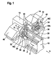
- a first embodiment of a machine tool according to the invention formed as a lathe, shown in Fig. 1, includes a as a whole with 10 designated machine frame, on which a spindle housing 12 is arranged in which a workpiece spindle 14 is rotatably mounted which in turn is relative to the spindle housing 12 about a spindle axis 16 is rotatable and a workpiece holder 18, for example in the form of a Has chuck through which a workpiece W in the workpiece spindle 14 is recordable and fixable.
- the spindle housing 12 is either relative to the machine frame 10 arranged stationary or arranged on a carriage 20, which by Longitudinal guides 22 on the machine frame 10 in a parallel to the spindle axis 16 extending Z direction is guided.
- tool carrier 30 are provided, which are designed for example as a tool turret and each have a turret housing 32, against which a turret head 34 is rotatable about a turret axis 36.
- Each of these turret heads 34 now carries a variety of tools WZ or WZ with which the workpiece W can be processed.
- Each of the tool turrets 30 is, for example, by a slide system 40 compared to the machine frame 10 at least in the Z direction parallel to Spindle axis 16 as well as in an X direction, that is, transversely to the spindle axis 16 movable towards this, preferably still in a Y direction, which is transverse runs to the Z and X directions.
- the workpiece W is machined in a work space 42 in which the workpiece W protrudes into and in which the tools WZ are arranged.
- two measuring devices on the machine tool 50 are provided, which are each capable of in a detection plane 60 to record the geometry data of objects that are being represented, whereby the detection levels 60 within a starting from the respective Measuring device in an observation direction 62 extending detection spaces 64 lie, and transversely, that is, in particular perpendicular to the Observation directions 62 extend.
- the detection planes 60 preferably lie in one through the spindle axis 16 and in the X-direction running geometric plane 66, thus runs parallel to the X direction and Z direction and also lie Detection spaces 64 on both sides next to the spindle axis 16, respectively at a distance from this, which is of the order of a maximum Workpiece radius is so that there is the possibility of being in the working position Tool WZ extending in the X / Z plane 66, for example in front and / or after machining the workpiece W.
- the measuring devices 50 are arranged so that each of the tool carriers 30 is assigned its own measuring device 50.
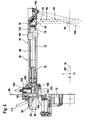
- each of the measuring devices 50 comprises one starting from one Wall 68 of the work space 42 extending into the work space 42 Arm 70, which has a tubular housing 72 for a whole with 74th designated imaging optics, for example, a deflecting mirror 76 and a telescope optics 78, one of which comprises the detection space 64 defining observation beam path 80 starting from a Observation opening 82 of the housing 72 with an external branch 84 in the Direction of observation 62 extends and meets the detection plane 60.
- imaging optics for example, a deflecting mirror 76 and a telescope optics 78
- Extending internal branch 86 of the observation beam path 80 is through deflected the deflecting mirror 76, passes through the telescope optics 78 and enters an image acquisition unit 90 in which an electronic camera module 92 is arranged.
- the imaging optics 74 is constructed so that it the detection plane 60 onto a detector surface 94 of the electronic Camera module 92 sharp images.
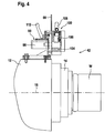
- the arm 70 comprising the tubular housing 72 is detachable in one Bracket 100 mountable, namely by an arranged on the arm 70 Insert pin 102, which in a pin receptacle 104 of the bracket 100 insertable and by a mounted on the pin receptacle 104 Clamping body 106 in the pin receptacle 104 precisely and repeatably is definable.
- the clamping body 106 is preferably actuated by a clamping body 108 for fixing the insertion pin 102 towards it movable, the clamping body actuation 108 is manually operable.
- the fixation of the arm 70 via the insertion pin 102 and the pin receptacle 104 takes place, for example, when the insertion pin 102 is on the usual plug-in pin for tool holders and the pin holder 104 is also designed accordingly, precise and repeatable.
- the holder 100 is preferably on a working space 42 facing Side of the wall 68 arranged while on a the work space 42 facing away from the wall 68, the image capture unit 90 on the Bracket 100 is arranged.
- this includes a housing 96, which is also releasable with the holder 100, for example via a Fixing device 112 is connected.
- the internal branch extends 86 of the observation beam path 80 also through the insertion pin 102 and through the holder 100 to the electronic camera module 92, with the internal branch 86 all the way from the electronic Camera module 92 to the observation opening 82 through both Bracket 100 and the adjoining arm 70 opposite the Conditions in the work space 42 is protected while the external one Branch 84 starting from the observation opening 82 in the observation direction 62 spreads freely in the work area 42 up to the detection level 60.
- the arm 70 can thus be inserted into the holder 100 in order to to bring a measuring position M, for example if one of the tools WZ should be measured in the detection plane 60, and after the measurement there is the possibility of detaching the arm 70 from the holder 100, for example manually remove from the work space 42 to the arm 70 in to bring a rest position, being used to protect the electronic camera module 92 a blind plug not shown in the drawing in FIG Pin receptacle 104 is used.
- the arm 70 extends with his Longitudinal axis 122 preferably approximately parallel to the spindle axis 16 and the external branch 84 of the observation beam path preferably extends transverse to the spindle axis 16 and transverse to the X direction and perpendicular to Acquisition level 60.
- the holder 100 to connect directly to the machine frame 10.
- the bracket 100 on the spindle housing 12 on the Machine frame 10 supported, thus with a stationary arrangement of the Spindle housing 12 is stationary relative to the machine frame 10 Arrangement of the measuring device 50 is present or in the case of a relative to Machine frame 10 movable spindle housing 12 a movable Arrangement of the measuring device 50, in which the position of the external branch 84 of the observation beam path 80 in the working space 42 at least relatively to the spindle housing 12 is set precisely and repeatably.
- the case is a relative position of the spindle housing 12 to the machine frame 10 by a machine controller 130 which determines the position of the spindle housing 12 defines defined relative to the machine frame 10, based on the detection relative to the position of the spindle housing 12 by the machine controller 130 to the machine frame 10 can be determined.
- the position of the external branch 84 of the observation beam path 80 is thus located relative to the machine frame 10 or is always via the machine control 130 can be determined with the necessary precision.
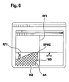
- the measuring device 50 has the possibility of one object detected by the external branch 84 of the observation beam path 80, for example one of those extending in the detection plane 60 Tools WZ, one that appears in the detection plane 60 as a silhouette geometric outer contour AK, for example in the area of a Tool tip, to be detected by the fact that the machine control 130 positioning an image of the outer contour AK relative to reference lines RF1 and RF2 takes place, which in the simplest case forms a crosshair Represent straight lines and their position relative to a reference point BP (Fig. 5) on the machine frame 10, for example a defined reference point BP on the spindle axis 16, either fixed or by the machine control 130 can be determined (FIGS. 3, 6).
- the position of a reference point BPWZ, (Fig. 6) of the tool WZ, in which depicts the outer contour AK obtained by shadow formation in the reference plane 60 touches the reference lines RF1 and RF2 and the Position of a corresponding reference point BPWT (Fig. 2) of the tool carrier 30, can be determined by the machine controller 130 and can thus be related to the position of the reference lines RF1 and RF2 relative to the reference point BP on the machine frame 10, which at immovable spindle housing 12 by the arrangement of the measuring device 50 relative to the reference point BP of the machine frame 10 can be set or is displaceable by the machine controller 130 Spindle housing 12 can be determined by the machine controller 130.
- the reference lines RF1 and RF2 can with the solution according to the invention either realized in a known manner as crosshairs in the telescope optics 78 and are imaged on the electronic camera module 92 or but also as in the image processing unit 120, for example one Memory 124 of the same, stored record for generating the Reference lines RF1 and RF2, for example by defining certain ones Pixel rows of the electronic camera module 92 as reference lines RF1 and RF2, which thus represent software-generated reference lines.
- AK is used to visually check the position of the outer contour the tool tip WS of the tool WZ the image processing unit 120 provided with a screen 126 that the from the electronic camera module 92 optical information acquired for a machine operator is enlarged represents and in particular the position of the outer contour AK relative to the Reference lines RF1 and RF2 show, as shown enlarged in FIG. 6.
- the tool WZ stands with the outer contour AK of the tool tip WS in an exactly defined by the reference lines RF1 and RF2 Position relative to that of the machine controller 130 by moving the tool carrier 30 reached relative position of the Reference point BPWT of the tool carrier 30 with respect to the reference point BP can be placed on the machine frame 10.
- Such a measurement makes it possible to eliminate all positioning errors the reference point BPWZ of the tool WZ relative to the tool holder WH and positioning error of the tool holder WH and relative to Correct tool carrier 30.
- the image processing unit 120 also includes the machine controller 130 is directly coupled and thus the assignment of the through the reference lines RF1 and RF2 to the reference position actually the position of the Reference point BPWT of the tool carrier 30 through direct communication between the image processing unit 120 and the machine controller 130 is available.
- the outer contour AK is created in the reference lines RF1 and RF2 through manual operation of machine control 130 and thus manually controlled movement of the slide system 40 for as long as until the outer contour AK touches the reference lines RF1 and RF2 the operator reviewing the concern on the screen 126 can be.
- the image processing unit 120 via a Program the distance of the outer contour AK, for example in the X direction of the reference line RF1 and in the Z direction from the reference line RF2 and transmits these distance values to a measurement controller 132, which the The machine controller 130 then controls the machine controller 130 the carriage system 40 moves such that the distances in the X direction and The Z direction gradually decreases until the reference lines touch RF1 in the X direction and RF2 in the Z direction.
- This state is then again from the image processing unit 120 of the Machine controller 130, which is capable of being transmitted due to this existing data on the position of the reference point BPWT of the tool holder 30 this position then the corresponding position of the outer contour Assign AK of the tool WZ, preferably tool-specifically, so that the machine controller 130 in a tool file 134 this relative position of the outer contour AK to the position of the reference point BPWT of the tool carrier 30 stored and also for later Editing operations can be used.
- Such a backlight 140 can either be on the external one Branch 84 of the observation beam path 80 opposite side of the Detection plane 60 arranged or generate diffuse radiation sources by diffuse reflection of the light from a radiation source arranged on the arm 70 142, the radiation preferably being one outside the visible Region in the infrared.
- the generation of diffuse background light 140 by means of that on the arm 70 arranged radiation source 142 is preferably done by illuminating of the work space 42 bounding walls and covers, preferably have a reflective but brushed surface and therefore result in the diffuse background light 140 even with direct illumination.
- a marking light source 144 on the arm 70 is provided which generates a light radiation field 146 which serves either for a machine operator in the work area 42 to indicate where Approximately the detection space 64 runs, the operator, for example the fact that the tool entering the detection space 64 with a Wavelength is illuminated in the visible range, can recognize that the Tool WZ has now reached the detection area 64 and thus through the measuring device 50 can be measured.
- the processes can be started with which the outer contour AK Tip WS of the tool WZ detected and their approximation to the reference lines RF1 and RF2 can be achieved in the manner described at Touch the reference lines RF1 and RF2 the relative position of the outer contour AK relative to the position of the reference point BPWT of the tool carrier 30 to be able to determine.
- the arm 70 is preferably provided with a contact unit 148, which with a a counter-contact unit 150 representing the counterpart on the holder 100 is necessarily in operative connection when the insertion pin 102 of the arm 70 is inserted into the pin receptacle 104 of the holder 100.
- the contact unit 148 is necessarily from the counter-contact unit 150 then releasable when the insertion pin 102 of the arm 70 out of the pin receptacle 104 is pulled out to the arm 70 from the work space 42 to remove.
- the Possibility of using the arm 70 as an object, not the workpiece WZ to measure, but a workpiece W, its being in the detection plane 60 lying outer contour AK is also captured as a silhouette.
- Another possibility is to mount the measuring device with the arm 70 not only to be used to measure the tool WZ or the workpiece W, but the image capture unit 90 with the electronic To use camera block 92 to a machining process of Workpiece W through the tool WZ, being in the already described way through the imaging optics 74 shown in the arm 70 contours emerging in the detection plane 60 on the electronic ones Camera module 92 imaged and by the image capture unit 90 can be detected.
- imaging optics 74 are each adapted to the geometry data to be recorded and thus, for example, an adjustment of the extent of the Detection space 64 and the position of the detection plane 60 to the different Tasks can be done.
- the arm 70 ' is the Measuring device 50 'designed such that in the tubular housing 72' not only the imaging optics 74 with the deflection mirror 76 and the telescope optics 78 are arranged, but the housing 72 'simultaneously as a housing for the image acquisition unit 90 and the electronic camera module 92 serves so that the imaging optics 74 together with the image acquisition unit 90 a form an integral unit enclosed by the housing 72 ', as a whole be moved from the rest position to the measuring position M and vice versa can.
- inductively or capacitively interacting information transmission units to provide that is even better than mechanical Contacts for frequent connection and disconnection Information transmission, in particular from the electronic camera module 92 to the image processing unit 120.
- the second exemplary embodiment is the same as the same reference numerals as used in the first embodiment, with the same Provide reference numerals so that the full content of this part on the first embodiment is referred to.
- an imaging optical system 74 is described, which is capable of one To map the detection plane onto the detector surface 94 of the camera module 92.
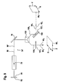
- the imaging optics 74 ' are designed such that the observation beam path 80' after the deflecting mirror 76 enters a beam splitter 155 from which a first branch 156 1 and a second branch 156 2 emerge.
- the first branch 156 1 passes through a first optical switching element 157 1 , from which the first external branch 84 1 of the observation beam path then emerges, which leads to the first detection plane 60 1 , which is arranged in a known manner and is parallel to the X direction and the Z direction Machine tool runs.
- the second branch 156 2 also passes through an optical switching element 157 2 and also strikes a deflecting mirror 158, so that after this a second external branch 84 2 of the observation beam path 80 'propagates in the direction of a second detection plane 60 2 , which in this case however, extends parallel to the X direction and the Y direction.
- the observation beam path 80 ' is now coordinated such that, depending on which of the optical switching elements 157 1 or 157 2 allows the observation beam path 80' to pass, either an image of an object extending in the first detection plane 60 1 or an image of an object in the second detection level 60 2 on the detector surface 94 of the electronic camera module 92 and thus there is the possibility of detecting an object alternately in one detection level 60 1 or the other detection level 60 2 .
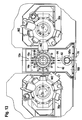
- a fourth embodiment of a machine tool For example, shown in Figs. 10 and 11 are two each other opposed workpiece spindles 14a and 14b are provided, each of the workpiece spindles 14a and 14b, for example two tool carriers 30a or 30b are assigned.
- the measuring device 50 is constructed in the same way as in the first embodiment, but with the difference that on opposite walls 68a and 68b of the work space 42 brackets 100a and 100b are provided and the arm 70 either in the holder 100a or can be inserted into the holder 100b and thus the imaging optics 74 either with the image acquisition unit 90a or the identically designed image acquisition unit 90b, both of which cannot be removed are, cooperates to the tools WZ the tool carrier To be able to measure 30a or 30b.
- opposite workpiece spindles 14a and 14b each have only one measuring device 50'a, 50'b assigned to the machine frame 10 facing side of the respective spindle axes 16a and 16b is arranged, the directions of observation 62 each from the arms 70 to the Spindle axes 16a, 16b and thus directed away from the machine frame 10 are.
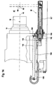
- the measuring device 50 " is preferred arranged in a foot region 160 of the spindle housing 12, specifically such that the arm 70 "from the measuring position M shown in FIG. 14, in which the arm over the foot area 160 of the spindle housing 12 in the Working space 42 protrudes, so that the detection space 64 on one of the workpiece spindle 14 facing away from the workpiece W and from the Spindle axis 16 is penetrated, and in a rest position shown in Figure 15 R is retractable, in which the arm 70 ′′ is retracted into the foot region 160 is, and no longer protrudes into the working space 42.
- arm 70 encodes the housing 72 "for the imaging optics 74, which in principle are designed in the same way is as in the previously described embodiments and in particular has the deflecting mirror 76 and the telescope optics 78.
- the tubular housing 72 ′′ for the imaging optics 74 is included at the end of the arm 70 "arranged on the end body 162, on the one hand closes the tubular housing 72 'and on the other hand on one of the tubular Housing 72 "opposite side of the image acquisition unit 90 carries over the housing 96, in which the electronic camera module 92 is arranged as described.
- the end body 162 has a passage 164 through which the internal branch 86 of the observation beam path 80 through the terminating body 162 can pass through and enter the image acquisition unit 90, to hit the detector surface 94 of the electronic camera module 92.
- the housing 72" forms with the housing 96 of the image acquisition unit 90 a firmly connected unit, but in such a way that the entire image acquisition unit 90 with its housing 96 and essentially also the closing body 162 both in the measuring position M and in the rest position R on a side facing away from the working space 42 End wall 168 of the foot area 160 lie and thus against influences from the Work space 42 are arranged protected.
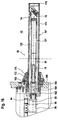
- the entire measuring device 50 is fixed by a holder 170, which on the front wall 168 adjacent to the working space 24 Foot area 160 is held and on the one hand comprises a guide bush 172, the arm 70 "in the region of an outer tube 174 in the direction of its longitudinal direction 122 slidably guides, so that the arm 70 "of that shown in Figure 16, essentially protruding into the working space 42 measuring position M can be brought into the rest position R shown in FIG. 15, in which the arm 70 "with an end cover 176 the guide sleeve 172 of the bracket 170 closes so that the entire arm 70 "substantially in the foot region 160 of the spindle housing 12 and outside the Working space 42 is arranged.
- first form-locking element 180 and the second Form-locking element 182 designed as rings with serration teeth, such as used for example for the exact positioning of revolver heads become.
- the first positive locking element 180 is arranged on the holder 170 in such a way that the second form-locking element 182 in this then completely engages and is positioned exactly by this when the arm 70 "in its Measuring position M stands.
- a displacement drive 190 for example in the form of a Hydraulic or pneumatic cylinder with a cylinder housing 192 in the Base area 160 arranged stationary, while one on the cylinder housing 192 guided actuator 194 of the displacement drive 190 on the closing body 162 acts and is preferably firmly connected to this.
- the form-locking elements 180 are thus also due to the displacement drive 190 and 182 are compressible into one another for precise and repeatable positioning of the arm 70 ".
- the actuator Arm 70 “additionally relative to the cylinder housing 192 on the way to Rest position performed, so that in the rest position R the arm 70 "on the one hand in the guide sleeve 172 is guided and on the other hand via the actuator 194 and the cylinder housing 192 also again relative to the foot region 160 of the Spindle housing 12 is guided.
- a cable guide is also expedient with the end body 162 196 connected in the form of a drag chain, via which the electrical Lines from the image acquisition unit moved with the arm 70 " 90 to the stationary relative to the machine frame 10 Image processing unit 120 are guided.
- the shift drive 190 is preferably also via the image processing unit 120 controllable so that when performing a Measurement in the working space 42 by the measuring device 50 "is required Image processing unit 120 a method of the arm 70 "by means of the displacement drive 190 from the rest position R to the measuring position M. can and then in a known manner within the detection space 64 Geometry data of an object recorded in the manner described can be.
- the image processing unit controls 120 the sliding drive 190 so that the arm 70 "in its rest position R is brought and therefore outside the influences of the UZ in the work area stands.
- the detection space 64 is preferably this way in this exemplary embodiment arranged that the detection plane 60 runs through the spindle axis 16, and thus there is the possibility of all tools WZ, which are on the workpiece W to be used can be brought into the detection level 60 are to be measured by means of the measuring device 50 ".
- the detection space 64 preferably runs transversely to the spindle axis 16, However, this is interspersed across the middle.
- each of the work spindles 14a, 14b is one Measuring device 50 'assigned so that in front of each of the work spindles 14a, 14b clamped workpiece W the respective detection space 64 lies in the tools WZ then used on this workpiece W. can be measured.
- the workpiece W in the respective workpiece spindle 14 is held, at least optically, for example by Silhouette to capture.
- the measuring accuracy of the expansion of the workpiece W transverse to the spindle axis depends on the quality of the guidance of the arm 70 "on the way from the Rest position R in the measuring position M or vice versa and can by a precise guidance of the arm 70 should also be sufficiently precise.
- measuring device 50 "a relative is moved to the spindle housing 14a in the measuring position and the workpiece W held in the workpiece spindle 14b and through with the machine control 130 controlled and thus in terms of travel known method of the workpiece spindle 14b relative to the measuring device 50 "a is moved.
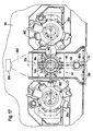
- a sixth embodiment shown in Fig. 17, corresponds to Structure in principle that of the fifth embodiment.
- a Wide-angle camera 200 which has an observation area 202 which is so large that all within the observation area 202 tools in the working position are independent of the position of the tool carrier 30 carrying these tools WZ, so that in each position of the tool carrier 30, the local position of the in the working position standing tool WZ captured by the wide-angle camera 200 can be.
- the image of the wide-angle camera 200 therefore also becomes the image processing unit 120 transmitted and this is able to the rough position of the tool tool in the work area 42 and the machine control 130 to be controlled so that the tool WZ in the detection area 64 is moved to measure there by means of the measuring device 50 " to be able to.
- the wide-angle camera 200 can generally be used to take one Document the processing process, the image data preferably compressed by conventional compression methods and thus saves space are storable.
- the start of the machining process and is preferably displayed the end of the machining process by a start signal and a stop signal, which is generated by the machine controller 130 of the image processing unit 120 is transmitted, which then between the start and the stop signal completely records and saves the machining process.
- the sixth embodiment is designed in the same way and also works in the same way as the fifth embodiment, so that on the explanations of the fifth embodiment and with regard to parts similar to the preceding exemplary embodiments on the explanations full reference to the preceding exemplary embodiments can be taken.
Landscapes
- Engineering & Computer Science (AREA)
- Mechanical Engineering (AREA)
- Physics & Mathematics (AREA)
- Optics & Photonics (AREA)
- Machine Tool Sensing Apparatuses (AREA)
- Length Measuring Devices By Optical Means (AREA)
Abstract
Description
- Figur 1
- eine perspektivische Ansicht eines ersten Ausführungsbeispiels einer erfindungsgemäßen Werkzeugmaschine;
- Figur 2
- eine Ansicht des ersten Ausführungsbeispiels in Richtung des Pfeils 1 in Figur 1;
- Figur 3
- ein Schnitt längs Linie B-B in Figur 2 durch das erfindungsgemäße Meßsystem unter Weglassung des Werkzeugträgers in Figur 1;
- Figur 4
- eine Schnittdarstellung entsprechend Figur 3 bei aus dem Arbeitsraum entnommenem Gehäuse der Abbildungsoptik;
- Figur 5
- eine vergrößerte Darstellung des Schnitts durch das Meßsystem gemäß Figur 3;
- Figur 6
- eine vergrößerte Darstellung der auf einem Bildschirm einer Bildverarbeitungseinheit erkennbaren Geometriedaten relativ zu Referenzdaten;
- Figur 7
- eine schematische Darstellung der verschiedenen, durch das erste Ausführungsbeispiel möglichen Messungen;
- Figur 8
- ein Schnitt ähnlich Figur 5 durch eine erfindungsgemäße Meßeinrichtung eines zweiten Ausführungsbeispiels einer erfindungsgemäßen Werkzeugmaschine;
- Figur 9
- eine schematische Darstellung einer Abbildungsoptik eines erfindungsgemäßen Meßsystems eines dritten Ausführungsbeispiels einer erfindungsgemäßen Werkzeugmaschine;
- Figur 10
- eine Darstellung auf einer Werkzeugmaschine gemäß einem vierten Ausführungsbeispiel einer erfindungsgemäßen Werkzeugmaschine;
- Figur 11
- eine schematische Darstellung der verschiedenen Einsatzmöglichkeiten gemäß dem vierten Ausführungsbeispiel;
- Figur 12
- eine perspektivische Draufsicht auf eine Werkzeugmaschine gemäß einem fünften Ausführungsbeispiel einer erfindungsgemäßen Werkzeugmaschine;
- Figur 13
- eine Ansicht des fünften Ausführungsbeispiels mit Blick in Richtung des Pfeils C in Figur 12;
- Figur 14
- einen Schnitt durch das Meßsystem des fünften Ausführungsbeispiels längs Linie D-D in Figur 13 bei in Meßstellung stehender Meßeinrichtung;
- Figur 15
- einen Schnitt ähnlich Figur 14 bei in Ruhestellung stehender Meßeinrichtung;
- Figur 16
- eine vergrößerte Darstellung des Schnitts gemäß Figur 14 durch das Meßsystem des fünften Ausführungsbeispiels und
- Figur 17
- eine Ansicht eines sechsten Ausführungsbeispiels entsprechend Figur 13.
Claims (50)
- Werkzeugmaschine umfassend
ein Maschinengestell (10), einen Arbeitsraum (42), in welchem eine Bearbeitung eines Werkstücks (W) mittels eines Werkzeugs (WZ) durch Bewegung derselben relativ zueinander erfolgt, einen am Maschinengestell (10) angeordneten Werkstückträger (14) mit einer Aufnahme (18) für das Werkstück (W), einen am Maschinengestell (10) angeordneten Werkzeugträger (30) mit einer Aufnahme (34) für das Werkzeug (WZ), eine Maschinensteuerung (130) zur Durchführung der Bewegung von Werkstück (W) und Werkzeug (WZ) relativ zueinander und eine optische Meßeinrichtung (50) zum Erfassen von Geometriedaten von mindestens einem im Arbeitsraum (42) angeordneten Objekt (WZ, W) in einer innerhalb eines Erfassungsraums (64) liegenden Erfassungsebene (60) relativ zu einem Maschinenbezugspunkt (BP), dadurch gekennzeichnet, daß die Meßeinrichtung (50) eine elektronische Bilderfassungseinheit (90) und eine dieser zugeordnete Abbildungsoptik (74) aufweist, daß die Abbildungsoptik (74) ein innerhalb des Erfassungsraums (64) angeordnetes Objekt (WZ, W) auf die Bilderfassungseinheit (90) abbildet und daß der Bilderfassungseinheit (90) eine Bildverarbeitungseinheit (120) zugeordnet ist, mit welcher aufgrund von Geometriedaten des Objekts (WZ, W) und Referenzdaten (RF1, RF2) eine Relativposition des Objekts (WZ, W) zu dem Maschinenbezugspunkt (BP) bestimmbar ist. - Werkzeugmaschine nach Anspruch 1, dadurch gekennzeichnet, daß die Erfassung der Relativposition des Objekts (WZ, W) in mindestens einer Meßstellung (M) der Meßeinrichtung (50) erfolgt.
- Werkzeugmaschine nach Anspruch 2, dadurch gekennzeichnet, daß der Erfassungsraum (64) und die Erfassungsebene (60) in mehrere Meßstellungen (M) bewegbar sind.
- Werkzeugmaschine nach Anspruch 2 oder 3, dadurch gekennzeichnet, daß der Meßeinrichtung (50) eine Positionserkennungseinrichtung (198) zugeordnet ist, mit welcher in der jeweiligen Meßstellung (M) die Position des Erfassungsbereichs (64) der Erfassungsebene (60) und der durch die Referenzdaten (RF1, RF2) repräsentierten Orte relativ zum Maschinenbezugspunkt (BP) bestimmbar sind.
- Werkzeugmaschine nach einem der voranstehenden Ansprüche, dadurch gekennzeichnet, daß die Abbildungsoptik (74) in einem sich in der Meßstellung (M) in dem Arbeitsraum (42) erstreckenden Gehäuse (72) angeordnet ist.
- Werkzeugmaschine nach Anspruch 5, dadurch gekennzeichnet, daß sich das Gehäuse (72) in der Meßstellung (M) ausgehend von einem den Arbeitsraum (42) begrenzenden Element (68, 168) in diesen hinein erstreckt.
- Werkzeugmaschine nach Anspruch 5 oder 6, dadurch gekennzeichnet, daß das Gehäuse (72') zusätzlich zu der Abbildungsoptik (74) die elektronische Bilderfassungseinheit (90) aufnimmt.
- Werkzeugmaschine nach Anspruch 5 oder 6, dadurch gekennzeichnet, daß die elektronische Bilderfassungseinheit (90) in einem eigenen, von dem Gehäuse (72) der Abbildungsoptik (74) separaten Gehäuse (96) angeordnet ist.
- Werkzeugmaschine nach Anspruch 8, dadurch gekennzeichnet, daß die elektronische Bilderfassungseinheit (90) von dem Gehäuse (72) der Abbildungsoptik (74) lösbar ist.
- Werkzeugmaschine nach einem der Ansprüche 5 bis 9, dadurch gekennzeichnet, daß das Gehäuse (72) der Abbildungsoptik (74) von der Meßstellung (M) in eine Ruhestellung (R) bewegbar ist.
- Werkzeugmaschine nach Anspruch 10, dadurch gekennzeichnet, daß das Gehäuse (72) der Abbildungsoptik (74) aus dem Arbeitsraum (42) heraus in die Ruhestellung (R) bewegbar ist.
- Werkzeugmaschine nach Anspruch 10 oder 11, dadurch gekennzeichnet, daß das Gehäuse (72) der Abbildungsoptik (74) in der Ruhestellung (R) gegen Spänebeaufschlagung und/oder Kühlmittelbeaufschlagung geschützt ist.
- Werkzeugmaschine nach einem der Ansprüche 5 bis 12, dadurch gekennzeichnet, daß das Gehäuse (72") mittels eines Antriebs (190) bewegbar ist.
- Werkzeugmaschine nach Anspruch 13, dadurch gekennzeichnet, daß das Gehäuse (72") durch den Antrieb (190) in den Arbeitsraum (42) hinein und aus diesem heraus bewegbar ist.
- Werkzeugmaschine nach einem der Ansprüche 10 bis 14, dadurch gekennzeichnet, daß das Gehäuse (72") in Richtung quer zu einer Bewegungsachse (X) des Werkzeugs (WZ) bei der Bearbeitung des Werkstücks (W) bewegbar ist.
- Werkzeugmaschine nach einem der Ansprüche 5 bis 15, dadurch gekennzeichnet, daß eine Positioniereinrichtung (102, 104; 180, 182) vorgesehen ist, mit welcher das Gehäuse (72) mitsamt der Abbildungsoptik (74) in der Meßstellung (M) im Arbeitsraum (42) exakt positionierbar ist.
- Werkzeugmaschine nach Anspruch 16, dadurch gekennzeichnet, daß mit der Positioniereinrichtung (102, 104; 180, 182) das Gehäuse (72) der Abbildungsoptik (74) im Arbeitsraum (42) wiederholgenau positionierbar ist.
- Werkzeugmaschine nach Anspruch 16 oder 17, dadurch gekennzeichnet, daß die Positioniereinrichtung (102, 104; 180, 182) das Gehäuse (72) durch Formschluß exakt positioniert.
- Werkzeugmaschine nach einem der Ansprüche 16 bis 18, dadurch gekennzeichnet, daß das Gehäuse (96) der Bilderfassungseinheit (90) durch die Positioniereinrichtung (102, 104) exakt relativ zum Gehäuse (72) der Abbildungsoptik (74) positionierbar ist.
- Werkzeugmaschine nach einem der Ansprüche 16 bis 19, dadurch gekennzeichnet, daß der Positioniereinrichtung (180, 182) eine Führung (190) für eine Bewegung des Gehäuses (72") der Abbildungsoptik (74) in den Arbeitsraum (42) hinein und aus diesem heraus zugeordnet ist.
- Werkzeugmaschine nach einem der Ansprüche 16 bis 20, dadurch gekennzeichnet, daß in der Meßstellung (M) des Gehäuses (72) der Abbildungsoptik (74) die elektronische Bilderfassungseinheit (90) für die Abbildungsoptik (74) außerhalb des Arbeitsraums (42) angeordnet ist.
- Werkzeugmaschine nach einem der voranstehenden Ansprüche, dadurch gekennzeichnet, daß die Meßeinrichtung (50) eine Außenkontur (AK) des Objekts (WZ, W) erfaßt.
- Werkzeugmaschine nach einem der voranstehenden Ansprüche, dadurch gekennzeichnet, daß die Abbildungsoptik (74) in einer festgelegten Erfassungsebene (60) liegende geometrische Konturen (AK) des Objekts (WZ, W) auf die Bilderfassungseinheit (90) abbildet.
- Werkzeugmaschine nach Anspruch 22 oder 23, dadurch gekennzeichnet, daß die Meßeinrichtung (50) durch von einer der Erfassungsebene (60) gegenüberliegenden Seite kommendes diffuses Hintergrundlicht (140) sich in der Erfassungsebene (60) abzeichnende Konturen (AK) erfaßt.
- Werkzeugmaschine nach Anspruch 24, dadurch gekennzeichnet, daß das diffuse Hintergrundlicht (140) durch auf einer der Abbildungsoptik (74) gegenüberliegenden Seite der Erfassungsebene (60) angeordnete Strahlungsquellen erzeugt wird.
- Werkzeugmaschine nach Anspruch 24, dadurch gekennzeichnet, daß das diffuse Hintergrundlicht (140) durch Reflexion von Licht erzeugt wird das von mindestens einer Strahlungsquelle (142) kommt, die auf derselben Seite der Erfassungsebene (60) angeordnet ist wie die Abbildungsoptik (74).
- Werkzeugmaschine nach Anspruch 26, dadurch gekennzeichnet, daß die Strahlungsquelle (142) an dem Gehäuse (72) der Abbildungsoptik (74) angeordnet ist.
- Werkzeugmaschine nach einem der Ansprüche 23 bis 27, dadurch gekennzeichnet, daß die Abbildungsoptik (74) derart ausgebildet ist, daß die Erfassung von Geometriedaten in zwei voneinander verschiedenen, nichtparallelen Erfassungsebenen (601, 602) möglich ist.
- Werkzeugmaschine nach Anspruch 28, dadurch gekennzeichnet, daß die Abbildungsoptik (74) von einer Erfassungsebene (601) auf die andere Erfassungsebene (602) umschaltbar ist.
- Werkzeugmaschine nach einem der voranstehenden Ansprüche, dadurch gekennzeichnet, daß die Abbildungsoptik (74) derart ausgebildet ist, daß mindestens eine Erfassungsebene (60) parallel zu mindestens einer der Bewegungsachsen (X, Y) verläuft, längs welcher eine Relativbewegung zwischen Werkstück (W) und Werkzeug (WZ) zur Bearbeitung des Werkstücks (W) erfolgt.
- Werkzeugmaschine nach einem der voranstehenden Ansprüche, dadurch gekennzeichnet, daß das Werkstück (W) zumindest zur Durchführung mindestens eines Teils der Bearbeitung um eine Spindelachse (16) drehbar ist.
- Werkzeugmaschine nach Anspruch 31, dadurch gekennzeichnet, daß die eine Erfassungsebene (60) parallel zur Spindelachse (16) verläuft.
- Werkzeugmaschine nach Anspruch 31 oder 32, dadurch gekennzeichnet, daß eine Erfassungsebene (60) quer zur Spindelachse (16) verläuft.
- Werkzeugmaschine nach einem der voranstehenden Ansprüche, dadurch gekennzeichnet, daß mit der Meßeinrichtung (50) während einer Bewegung derselben im Arbeitsraum (42) Geometriedaten erfassbar sind.
- Werkzeugmaschine nach Anspruch 34, dadurch gekennzeichnet, daß die Bewegung der Meßeinrichtung (50) im Arbeitsraum (42) durch ein Meßsystem (198) erfassbar ist.
- Werkzeugmaschine nach Anspruch 34, dadurch gekennzeichnet, daß eine Erfassung der relativen Bewegung der Meßeinrichtung (50) zu dem die Geometriedaten aufweisenden Objekt im Arbeitsraum (42) durch eine gesteuerte Relativbewegung einer die Meßeinrichtung (50) oder das Objekt (W, WZ) tragenden Einheit (12) der Werkzeugmaschine zu dem zu erfassenden Objekt (W, WZ) bzw. der Meßeinrichtung (50) erfolgt.
- Werkzeugmaschine nach einem der voranstehenden Ansprüche, dadurch gekennzeichnet, daß eine den Erfassungsraum (64) durch ein Strahlenbündel (146) im sichtbaren Bereich optisch kennzeichnende Markierungslichtquelle (144) vorgesehen ist.
- Werkzeugmaschine nach Anspruch 37, dadurch gekennzeichnet, daß die Markierungslichtquelle (144) an dem Gehäuse (72) der Abbildungsoptik (74) angeordnet ist.
- Werkzeugmaschine nach einem der voranstehenden Ansprüche, dadurch gekennzeichnet, daß der Bildverarbeitungseinheit (120) ein das Objekt darstellender Bildschirm (126) zugeordnet ist.
- Werkzeugmaschine nach einem der voranstehenden Ansprüche, dadurch gekennzeichnet, daß die Referenzdaten durch einen Referenzdatensatz (RF1,RF2) gebildet sind, welcher in der Bildverarbeitungseinheit (120) gespeichert ist.
- Werkzeugmaschine nach einem der voranstehenden Ansprüche, dadurch gekennzeichnet, daß die Referenzdaten mindestens einer Referenzlinie (RF1,RF2) entsprechen.
- Werkzeugmaschine nach Anspruch 41, dadurch gekennzeichnet, daß die Referenzdaten mindestens zwei sich kreuzenden Referenzlinien (RF1,RF2) entsprechen.
- Werkzeugmaschine nach Anspruch 42, dadurch gekennzeichnet, daß die Referenzdaten ein Fadenkreuz (RF1, RF2) darstellen.
- Werkzeugmaschine nach einem der voranstehenden Ansprüche , dadurch gekennzeichnet, daß die Bildverarbeitungseinheit (120) ein Bildverarbeitungsprogramm aufweist, welches ein Berühren von durch die Referenzdaten (RF1, RF2) bestimmten Orten durch den Geometriedaten des Objekts (WZ, W) entsprechenden Orten erkennt.
- Werkzeugmaschine nach Anspruch 44, dadurch gekennzeichnet, daß das Bildverarbeitungsprogramm ein Berühren der durch die Referenzdaten (RF1, RF2) bestimmten Orte von einem Übergreifen von der durch die Referenzdaten (RF1, RF2) bestimmten Orte unterscheidet.
- Werkzeugmaschine nach Anspruch 44 oder 45, dadurch gekennzeichnet, daß die Bildverarbeitungseinheit (120) über eine Vermessungssteuerung (132) auf die Maschinensteuerung (130) in dem Sinne einwirkt, daß das Objekt (WZ, W) in sich zunehmend verkleinerndem Abstand an die Referenzdaten (RF1,RF2) heranbewegbar ist.
- Werkzeugmaschine nach einem der voranstehenden Ansprüche, dadurch gekennzeichnet, daß der Bildverarbeitungseinheit (120) eine Kamera (200) zugeordnet ist, in deren Beobachtungsbereich (202) in Arbeitsstellung zum Werkstück (W) ausgerichtete Werkzeuge (WZ) stehen.
- Werkzeugmaschine nach Anspruch 47, dadurch gekennzeichnet, daß die Kamera (200) auf einer der Meßeinrichtung (50") gegenüberliegenden Seite des in der Werkstückaufnahme (14) zur Bearbeitung vorgesehenen Werkstücks (W) angeordnet ist.
- Werkzeugmaschine nach Anspruch 47 oder 48, dadurch gekennzeichnet, daß der Beobachtungsbereich (202) der Kamera (200) eine Ausdehnung aufweist, so daß alle einem zu bearbeitenden Werkstück (W) zugeordneten und in Arbeitsstellung stehenden Werkzeuge (WZ) von der Kamera erfassbar sind.
- Werkzeugmaschine nach einem der Ansprüche 47 bis 49, dadurch gekennzeichnet, daß mit der Bildverarbeitungseinheit (120) und der Kamera (200) ein Bearbeitungsprozess des Werkstücks (W) aufzeichenbar ist.
Priority Applications (1)
| Application Number | Priority Date | Filing Date | Title |
|---|---|---|---|
| SI200430913T SI1477274T1 (sl) | 2003-05-16 | 2004-05-12 | Obdelovalni stroj |
Applications Claiming Priority (6)
| Application Number | Priority Date | Filing Date | Title |
|---|---|---|---|
| DE10323673 | 2003-05-16 | ||
| DE10323673 | 2003-05-16 | ||
| DE10325387 | 2003-05-30 | ||
| DE10325387 | 2003-05-30 | ||
| DE10332913 | 2003-07-19 | ||
| DE10332913A DE10332913A1 (de) | 2003-05-16 | 2003-07-19 | Werkzeugmaschine |
Publications (3)
| Publication Number | Publication Date |
|---|---|
| EP1477274A2 true EP1477274A2 (de) | 2004-11-17 |
| EP1477274A3 EP1477274A3 (de) | 2006-03-22 |
| EP1477274B1 EP1477274B1 (de) | 2008-09-10 |
Family
ID=33032857
Family Applications (1)
| Application Number | Title | Priority Date | Filing Date |
|---|---|---|---|
| EP04011226A Expired - Lifetime EP1477274B1 (de) | 2003-05-16 | 2004-05-12 | Werkzeugmaschine |
Country Status (2)
| Country | Link |
|---|---|
| EP (1) | EP1477274B1 (de) |
| JP (1) | JP4786880B2 (de) |
Cited By (4)
| Publication number | Priority date | Publication date | Assignee | Title |
|---|---|---|---|---|
| EP2363238A3 (de) * | 2010-03-02 | 2013-01-02 | Traub Drehmaschinen GmbH & Co. KG | Werkzeugmaschine mit Werkstückmesseinrichtung |
| EP3257626A4 (de) * | 2015-02-13 | 2018-10-24 | Makino Milling Machine Co., Ltd. | Werkzeugformmessvorrichtung und werkzeugmaschine |
| CN109746789A (zh) * | 2017-11-08 | 2019-05-14 | 萨特隆股份公司 | 用于加工特别是眼镜镜片的光学工件的装置 |
| CN111531212A (zh) * | 2020-04-02 | 2020-08-14 | 洛阳拓博尔铁路设备有限公司 | 一种基于软件靴的钢轨铣削作业装置及控制方法 |
Families Citing this family (2)
| Publication number | Priority date | Publication date | Assignee | Title |
|---|---|---|---|---|
| CN102179724B (zh) * | 2011-03-16 | 2012-07-04 | 齐重数控装备股份有限公司 | 对接旋风刀盘状态变化时的精度检测方法 |
| CN114871851A (zh) * | 2022-06-02 | 2022-08-09 | 衢州职业技术学院 | 一种检测五轴曲面加工质量的数字化测试装置 |
Family Cites Families (12)
| Publication number | Priority date | Publication date | Assignee | Title |
|---|---|---|---|---|
| DE2941156C2 (de) * | 1979-10-10 | 1986-03-20 | Traub Gmbh, 7313 Reichenbach | Verfahren zum Ermitteln der Lage einer Werkzeugspitze in bezug auf einen Werkzeugschlitten einer numerisch gesteuerten Werkzeugmaschine, insbesondere Drehmaschine |
| US4966460A (en) * | 1987-10-28 | 1990-10-30 | The Ingersoll Milling Machine Company | Laser gauging of rotary cutting tools |
| JPH05297090A (ja) * | 1992-04-23 | 1993-11-12 | Fujitsu Ltd | 生体磁気計測装置 |
| JPH06134638A (ja) * | 1992-10-26 | 1994-05-17 | Osaka Kiko Co Ltd | 工具の自動照合認識装置 |
| JP2609823B2 (ja) * | 1993-12-27 | 1997-05-14 | ユーエイチティー株式会社 | 画像処理によるターゲットマークの中心位置検出方法 |
| US6301007B1 (en) * | 1998-05-29 | 2001-10-09 | The Regents Of The University Of California | Machine tool locator |
| DE19840801B4 (de) * | 1998-09-08 | 2005-09-15 | Walter Maschinenbau Gmbh | Werkzeugmaschine mit automatischer Prozesssteuerung/Überwachung und Verfahren zum Bearbeiten |
| JP4150448B2 (ja) * | 1998-09-17 | 2008-09-17 | 松下電器産業株式会社 | 部品認識装置及び方法 |
| DE10011804A1 (de) * | 2000-03-14 | 2001-09-20 | Inst Innovative Technologien T | Meßeinrichtung zur Bestimmung der Lage und Orientierung einer Bewegungsplattform einer Parallelkinematik |
| JP2001280915A (ja) * | 2000-03-29 | 2001-10-10 | Nikon Corp | 画像測定システム及び画像測定方法 |
| US6955284B2 (en) * | 2000-10-06 | 2005-10-18 | Pac Tec-Packaging Technologies Gmbh | Device for positioning a tool in relation to a workpiece |
| DE10131352A1 (de) * | 2001-06-26 | 2003-01-09 | Zoller Gmbh & Co Kg E | Verfahren und Vorrichtung zum Einschrumpfen von Werkzeugen, insbesondere Zerspanungswekzeugen |
-
2004
- 2004-05-12 EP EP04011226A patent/EP1477274B1/de not_active Expired - Lifetime
- 2004-05-13 JP JP2004143760A patent/JP4786880B2/ja not_active Expired - Fee Related
Cited By (9)
| Publication number | Priority date | Publication date | Assignee | Title |
|---|---|---|---|---|
| EP2363238A3 (de) * | 2010-03-02 | 2013-01-02 | Traub Drehmaschinen GmbH & Co. KG | Werkzeugmaschine mit Werkstückmesseinrichtung |
| EP3257626A4 (de) * | 2015-02-13 | 2018-10-24 | Makino Milling Machine Co., Ltd. | Werkzeugformmessvorrichtung und werkzeugmaschine |
| US10293448B2 (en) | 2015-02-13 | 2019-05-21 | Makino Milling Machine Co., Ltd. | Tool shape measurement apparatus and machine tool |
| CN109746789A (zh) * | 2017-11-08 | 2019-05-14 | 萨特隆股份公司 | 用于加工特别是眼镜镜片的光学工件的装置 |
| EP3488967A1 (de) * | 2017-11-08 | 2019-05-29 | Satisloh AG | Vorrichtung zur bearbeitung von optischen werkstücken, insbesondere brillengläsern |
| CN109746789B (zh) * | 2017-11-08 | 2021-05-28 | 萨特隆股份公司 | 用于加工光学工件的装置 |
| US11633827B2 (en) | 2017-11-08 | 2023-04-25 | Satisloh Ag | Device for processing optical workpieces, particularly spectacle lenses |
| CN111531212A (zh) * | 2020-04-02 | 2020-08-14 | 洛阳拓博尔铁路设备有限公司 | 一种基于软件靴的钢轨铣削作业装置及控制方法 |
| CN111531212B (zh) * | 2020-04-02 | 2021-05-28 | 洛阳拓博尔铁路设备有限公司 | 一种基于软件靴的钢轨铣削作业装置及控制方法 |
Also Published As
| Publication number | Publication date |
|---|---|
| EP1477274A3 (de) | 2006-03-22 |
| JP4786880B2 (ja) | 2011-10-05 |
| EP1477274B1 (de) | 2008-09-10 |
| JP2004338084A (ja) | 2004-12-02 |
Similar Documents
| Publication | Publication Date | Title |
|---|---|---|
| EP0520396B1 (de) | Automatische Werkzeugvermessung | |
| EP0947802B1 (de) | Messanordnung zur Erfassung von Dimensionen von Prüflingen, vorzugsweise von Hohlkörpern, insbesondere von Bohrungen in Werkstücken, sowie Verfahren zur Messung solcher Dimensionen | |
| EP2847539B1 (de) | Wechselbares beleuchtungsmodul für ein koordinatenmessgerät | |
| DE102012216908B4 (de) | Verfahren unter Verwendung einer Bildkorrelation zum Bestimmen von Positionsmessungen in einem Maschinenvisionssystem | |
| EP1554080B1 (de) | Werkzeughaltevorrichtung und verfahren zum positionieren eines werkzeugs | |
| DE10131352A1 (de) | Verfahren und Vorrichtung zum Einschrumpfen von Werkzeugen, insbesondere Zerspanungswekzeugen | |
| EP2284480A2 (de) | Koordinatenmessgerät sowie Verfahren zum Messen mit einem Koordinatenmessgerät | |
| CH684291A5 (de) | Operationsmikroskop zur rechnergestützten, stereotaktischen Mikrochirurgie, sowie Verfahren zu dessen Betrieb. | |
| EP3453487B1 (de) | Verfahren zum positionieren eines mittelpunkts auf einer geometrischen achse bei einer werkzeugmaschine | |
| DE102014210046B4 (de) | Operationsmikroskopsystem | |
| DE202017107827U1 (de) | Dreh /Schwenkkopf für optische Messtaster, Koordinatenmesssystem und Werkzeughalter | |
| EP0186726A1 (de) | Werkzeugmagazin | |
| EP1477274B1 (de) | Werkzeugmaschine | |
| DE102015104821A1 (de) | Chirurgisches Instrument, System, Haltearm sowie Verfahren | |
| EP2305417A2 (de) | Optisches Assistenzsystem für Werkzeugmaschinen | |
| EP3445528B1 (de) | Vorrichtung und verfahren zum einsetzen eines werkzeugs in eine werkzeugaufnahme | |
| DE19803679A1 (de) | Vorrichtung zur optischen Abtastung eines Objekts | |
| EP3848666A1 (de) | Fräsmaschine und fräsverfahren | |
| DE10361920B4 (de) | Vorrichtung und Verfahren zur Kontrolle von Werkzeugen | |
| DE19629616C2 (de) | Vorrichtung und Verfahren zum manuellen Einstellen, Messen, ggf. Prüfen von Werkzeugen für Bearbeitungsmaschinen | |
| EP0346288B1 (de) | Verfahren und Einrichtung zum berührungslosen Ausmessen eines Werkstückes | |
| EP4383026A2 (de) | Optisches erfassen einer aufnahmeeinrichtung für einwechselbare komponenten eines koordinatenmessgeräts | |
| DE10332913A1 (de) | Werkzeugmaschine | |
| DE3242532A1 (de) | Einrichtung zur automatischen und programmierten pruefung von teilen oder werkstuecken sowie elektrooptischer taster dafuer | |
| DE102008006418B4 (de) | Vorrichtung zur Bearbeitung von hohlen Werkstücken |
Legal Events
| Date | Code | Title | Description |
|---|---|---|---|
| PUAI | Public reference made under article 153(3) epc to a published international application that has entered the european phase |
Free format text: ORIGINAL CODE: 0009012 |
|
| AK | Designated contracting states |
Kind code of ref document: A2 Designated state(s): AT BE BG CH CY CZ DE DK EE ES FI FR GB GR HU IE IT LI LU MC NL PL PT RO SE SI SK TR |
|
| AX | Request for extension of the european patent |
Extension state: AL HR LT LV MK |
|
| RIN1 | Information on inventor provided before grant (corrected) |
Inventor name: KLAUSS, WALTER Inventor name: BAUMANN, ULRICH Inventor name: EITEL, MANFRED Inventor name: OSSWALD, ERNST Inventor name: MONZ, JOACHIM |
|
| RIC1 | Information provided on ipc code assigned before grant |
Ipc: B23Q 17/22 19850101ALI20051125BHEP Ipc: B23Q 17/24 19850101AFI20040831BHEP |
|
| PUAL | Search report despatched |
Free format text: ORIGINAL CODE: 0009013 |
|
| AK | Designated contracting states |
Kind code of ref document: A3 Designated state(s): AT BE BG CH CY CZ DE DK EE ES FI FR GB GR HU IE IT LI LU MC NL PL PT RO SE SI SK TR |
|
| AX | Request for extension of the european patent |
Extension state: AL HR LT LV MK |
|
| RIC1 | Information provided on ipc code assigned before grant |
Ipc: B23Q 1/00 20060101ALI20060202BHEP Ipc: B23Q 17/22 20060101ALI20060202BHEP Ipc: B23Q 17/24 20060101AFI20040831BHEP |
|
| 17P | Request for examination filed |
Effective date: 20060812 |
|
| AKX | Designation fees paid |
Designated state(s): AT BE BG CH CY CZ DE DK EE ES FI FR GB GR HU IE IT LI LU MC NL PL PT RO SE SI SK TR |
|
| 17Q | First examination report despatched |
Effective date: 20061220 |
|
| GRAP | Despatch of communication of intention to grant a patent |
Free format text: ORIGINAL CODE: EPIDOSNIGR1 |
|
| RAP1 | Party data changed (applicant data changed or rights of an application transferred) |
Owner name: TRAUB DREHMASCHINEN GMBH & CO. KG |
|
| GRAS | Grant fee paid |
Free format text: ORIGINAL CODE: EPIDOSNIGR3 |
|
| GRAA | (expected) grant |
Free format text: ORIGINAL CODE: 0009210 |
|
| AK | Designated contracting states |
Kind code of ref document: B1 Designated state(s): AT BE BG CH CY CZ DE DK EE ES FI FR GB GR HU IE IT LI LU MC NL PL PT RO SE SI SK TR |
|
| REG | Reference to a national code |
Ref country code: GB Ref legal event code: FG4D Free format text: NOT ENGLISH |
|
| REG | Reference to a national code |
Ref country code: CH Ref legal event code: EP |
|
| REG | Reference to a national code |
Ref country code: CH Ref legal event code: NV Representative=s name: KIRKER & CIE S.A. Ref country code: IE Ref legal event code: FG4D Free format text: LANGUAGE OF EP DOCUMENT: GERMAN |
|
| REF | Corresponds to: |
Ref document number: 502004008008 Country of ref document: DE Date of ref document: 20081023 Kind code of ref document: P |
|
| PG25 | Lapsed in a contracting state [announced via postgrant information from national office to epo] |
Ref country code: FI Free format text: LAPSE BECAUSE OF FAILURE TO SUBMIT A TRANSLATION OF THE DESCRIPTION OR TO PAY THE FEE WITHIN THE PRESCRIBED TIME-LIMIT Effective date: 20080910 |
|
| NLV1 | Nl: lapsed or annulled due to failure to fulfill the requirements of art. 29p and 29m of the patents act | ||
| REG | Reference to a national code |
Ref country code: IE Ref legal event code: FD4D |
|
| PG25 | Lapsed in a contracting state [announced via postgrant information from national office to epo] |
Ref country code: ES Free format text: LAPSE BECAUSE OF FAILURE TO SUBMIT A TRANSLATION OF THE DESCRIPTION OR TO PAY THE FEE WITHIN THE PRESCRIBED TIME-LIMIT Effective date: 20081221 Ref country code: IE Free format text: LAPSE BECAUSE OF FAILURE TO SUBMIT A TRANSLATION OF THE DESCRIPTION OR TO PAY THE FEE WITHIN THE PRESCRIBED TIME-LIMIT Effective date: 20080910 Ref country code: BG Free format text: LAPSE BECAUSE OF FAILURE TO SUBMIT A TRANSLATION OF THE DESCRIPTION OR TO PAY THE FEE WITHIN THE PRESCRIBED TIME-LIMIT Effective date: 20081210 |
|
| PG25 | Lapsed in a contracting state [announced via postgrant information from national office to epo] |
Ref country code: PT Free format text: LAPSE BECAUSE OF FAILURE TO SUBMIT A TRANSLATION OF THE DESCRIPTION OR TO PAY THE FEE WITHIN THE PRESCRIBED TIME-LIMIT Effective date: 20090210 Ref country code: SK Free format text: LAPSE BECAUSE OF FAILURE TO SUBMIT A TRANSLATION OF THE DESCRIPTION OR TO PAY THE FEE WITHIN THE PRESCRIBED TIME-LIMIT Effective date: 20080910 Ref country code: RO Free format text: LAPSE BECAUSE OF FAILURE TO SUBMIT A TRANSLATION OF THE DESCRIPTION OR TO PAY THE FEE WITHIN THE PRESCRIBED TIME-LIMIT Effective date: 20080910 Ref country code: NL Free format text: LAPSE BECAUSE OF FAILURE TO SUBMIT A TRANSLATION OF THE DESCRIPTION OR TO PAY THE FEE WITHIN THE PRESCRIBED TIME-LIMIT Effective date: 20080910 |
|
| PLBE | No opposition filed within time limit |
Free format text: ORIGINAL CODE: 0009261 |
|
| STAA | Information on the status of an ep patent application or granted ep patent |
Free format text: STATUS: NO OPPOSITION FILED WITHIN TIME LIMIT |
|
| PG25 | Lapsed in a contracting state [announced via postgrant information from national office to epo] |
Ref country code: EE Free format text: LAPSE BECAUSE OF FAILURE TO SUBMIT A TRANSLATION OF THE DESCRIPTION OR TO PAY THE FEE WITHIN THE PRESCRIBED TIME-LIMIT Effective date: 20080910 Ref country code: DK Free format text: LAPSE BECAUSE OF FAILURE TO SUBMIT A TRANSLATION OF THE DESCRIPTION OR TO PAY THE FEE WITHIN THE PRESCRIBED TIME-LIMIT Effective date: 20080910 |
|
| 26N | No opposition filed |
Effective date: 20090611 |
|
| PG25 | Lapsed in a contracting state [announced via postgrant information from national office to epo] |
Ref country code: IT Free format text: LAPSE BECAUSE OF FAILURE TO SUBMIT A TRANSLATION OF THE DESCRIPTION OR TO PAY THE FEE WITHIN THE PRESCRIBED TIME-LIMIT Effective date: 20080910 |
|
| BERE | Be: lapsed |
Owner name: TRAUB DREHMASCHINEN G.M.B.H. & CO. KG Effective date: 20090531 |
|
| PG25 | Lapsed in a contracting state [announced via postgrant information from national office to epo] |
Ref country code: MC Free format text: LAPSE BECAUSE OF NON-PAYMENT OF DUE FEES Effective date: 20090531 |
|
| PG25 | Lapsed in a contracting state [announced via postgrant information from national office to epo] |
Ref country code: CZ Free format text: LAPSE BECAUSE OF NON-PAYMENT OF DUE FEES Effective date: 20090512 Ref country code: SE Free format text: LAPSE BECAUSE OF FAILURE TO SUBMIT A TRANSLATION OF THE DESCRIPTION OR TO PAY THE FEE WITHIN THE PRESCRIBED TIME-LIMIT Effective date: 20081210 |
|
| REG | Reference to a national code |
Ref country code: SI Ref legal event code: KO00 Effective date: 20100115 |
|
| PG25 | Lapsed in a contracting state [announced via postgrant information from national office to epo] |
Ref country code: PL Free format text: LAPSE BECAUSE OF FAILURE TO SUBMIT A TRANSLATION OF THE DESCRIPTION OR TO PAY THE FEE WITHIN THE PRESCRIBED TIME-LIMIT Effective date: 20080910 Ref country code: SI Free format text: LAPSE BECAUSE OF NON-PAYMENT OF DUE FEES Effective date: 20090513 |
|
| PG25 | Lapsed in a contracting state [announced via postgrant information from national office to epo] |
Ref country code: BE Free format text: LAPSE BECAUSE OF NON-PAYMENT OF DUE FEES Effective date: 20090531 |
|
| PG25 | Lapsed in a contracting state [announced via postgrant information from national office to epo] |
Ref country code: GR Free format text: LAPSE BECAUSE OF FAILURE TO SUBMIT A TRANSLATION OF THE DESCRIPTION OR TO PAY THE FEE WITHIN THE PRESCRIBED TIME-LIMIT Effective date: 20081211 |
|
| PG25 | Lapsed in a contracting state [announced via postgrant information from national office to epo] |
Ref country code: LU Free format text: LAPSE BECAUSE OF NON-PAYMENT OF DUE FEES Effective date: 20090512 |
|
| PG25 | Lapsed in a contracting state [announced via postgrant information from national office to epo] |
Ref country code: HU Free format text: LAPSE BECAUSE OF FAILURE TO SUBMIT A TRANSLATION OF THE DESCRIPTION OR TO PAY THE FEE WITHIN THE PRESCRIBED TIME-LIMIT Effective date: 20090311 |
|
| PG25 | Lapsed in a contracting state [announced via postgrant information from national office to epo] |
Ref country code: TR Free format text: LAPSE BECAUSE OF FAILURE TO SUBMIT A TRANSLATION OF THE DESCRIPTION OR TO PAY THE FEE WITHIN THE PRESCRIBED TIME-LIMIT Effective date: 20080910 |
|
| PG25 | Lapsed in a contracting state [announced via postgrant information from national office to epo] |
Ref country code: CY Free format text: LAPSE BECAUSE OF FAILURE TO SUBMIT A TRANSLATION OF THE DESCRIPTION OR TO PAY THE FEE WITHIN THE PRESCRIBED TIME-LIMIT Effective date: 20080910 |
|
| PGFP | Annual fee paid to national office [announced via postgrant information from national office to epo] |
Ref country code: GB Payment date: 20120509 Year of fee payment: 9 |
|
| PGFP | Annual fee paid to national office [announced via postgrant information from national office to epo] |
Ref country code: AT Payment date: 20120426 Year of fee payment: 9 |
|
| PGFP | Annual fee paid to national office [announced via postgrant information from national office to epo] |
Ref country code: DE Payment date: 20130626 Year of fee payment: 10 Ref country code: CH Payment date: 20130514 Year of fee payment: 10 |
|
| PGFP | Annual fee paid to national office [announced via postgrant information from national office to epo] |
Ref country code: FR Payment date: 20130531 Year of fee payment: 10 |
|
| REG | Reference to a national code |
Ref country code: AT Ref legal event code: MM01 Ref document number: 407768 Country of ref document: AT Kind code of ref document: T Effective date: 20130531 |
|
| GBPC | Gb: european patent ceased through non-payment of renewal fee |
Effective date: 20130512 |
|
| PG25 | Lapsed in a contracting state [announced via postgrant information from national office to epo] |
Ref country code: AT Free format text: LAPSE BECAUSE OF NON-PAYMENT OF DUE FEES Effective date: 20130531 |
|
| PG25 | Lapsed in a contracting state [announced via postgrant information from national office to epo] |
Ref country code: GB Free format text: LAPSE BECAUSE OF NON-PAYMENT OF DUE FEES Effective date: 20130512 |
|
| REG | Reference to a national code |
Ref country code: DE Ref legal event code: R119 Ref document number: 502004008008 Country of ref document: DE |
|
| REG | Reference to a national code |
Ref country code: CH Ref legal event code: PL |
|
| PG25 | Lapsed in a contracting state [announced via postgrant information from national office to epo] |
Ref country code: LI Free format text: LAPSE BECAUSE OF NON-PAYMENT OF DUE FEES Effective date: 20140531 Ref country code: CH Free format text: LAPSE BECAUSE OF NON-PAYMENT OF DUE FEES Effective date: 20140531 |
|
| REG | Reference to a national code |
Ref country code: DE Ref legal event code: R119 Ref document number: 502004008008 Country of ref document: DE Effective date: 20141202 |
|
| REG | Reference to a national code |
Ref country code: FR Ref legal event code: ST Effective date: 20150130 |
|
| PG25 | Lapsed in a contracting state [announced via postgrant information from national office to epo] |
Ref country code: DE Free format text: LAPSE BECAUSE OF NON-PAYMENT OF DUE FEES Effective date: 20141202 |
|
| PG25 | Lapsed in a contracting state [announced via postgrant information from national office to epo] |
Ref country code: FR Free format text: LAPSE BECAUSE OF NON-PAYMENT OF DUE FEES Effective date: 20140602 |