EP1475915A2 - Passives optisches Netzwerk mit Mehrträger CDMA - Google Patents
Passives optisches Netzwerk mit Mehrträger CDMA Download PDFInfo
- Publication number
- EP1475915A2 EP1475915A2 EP04007858A EP04007858A EP1475915A2 EP 1475915 A2 EP1475915 A2 EP 1475915A2 EP 04007858 A EP04007858 A EP 04007858A EP 04007858 A EP04007858 A EP 04007858A EP 1475915 A2 EP1475915 A2 EP 1475915A2
- Authority
- EP
- European Patent Office
- Prior art keywords
- optical
- signal
- signals
- multiplier
- cdma
- Prior art date
- Legal status (The legal status is an assumption and is not a legal conclusion. Google has not performed a legal analysis and makes no representation as to the accuracy of the status listed.)
- Withdrawn
Links
Images


Classifications
-
- H—ELECTRICITY
- H04—ELECTRIC COMMUNICATION TECHNIQUE
- H04J—MULTIPLEX COMMUNICATION
- H04J14/00—Optical multiplex systems
- H04J14/005—Optical Code Multiplex
- H04J14/007—Orthogonal Optical Code Multiplex
-
- H—ELECTRICITY
- H04—ELECTRIC COMMUNICATION TECHNIQUE
- H04B—TRANSMISSION
- H04B10/00—Transmission systems employing electromagnetic waves other than radio-waves, e.g. infrared, visible or ultraviolet light, or employing corpuscular radiation, e.g. quantum communication
- H04B10/50—Transmitters
- H04B10/501—Structural aspects
- H04B10/503—Laser transmitters
-
- H—ELECTRICITY
- H04—ELECTRIC COMMUNICATION TECHNIQUE
- H04J—MULTIPLEX COMMUNICATION
- H04J14/00—Optical multiplex systems
- H04J14/02—Wavelength-division multiplex systems
- H04J14/0201—Add-and-drop multiplexing
- H04J14/0202—Arrangements therefor
- H04J14/0204—Broadcast and select arrangements, e.g. with an optical splitter at the input before adding or dropping
-
- H—ELECTRICITY
- H04—ELECTRIC COMMUNICATION TECHNIQUE
- H04J—MULTIPLEX COMMUNICATION
- H04J14/00—Optical multiplex systems
- H04J14/02—Wavelength-division multiplex systems
- H04J14/0201—Add-and-drop multiplexing
- H04J14/0202—Arrangements therefor
- H04J14/0205—Select and combine arrangements, e.g. with an optical combiner at the output after adding or dropping
-
- H—ELECTRICITY
- H04—ELECTRIC COMMUNICATION TECHNIQUE
- H04J—MULTIPLEX COMMUNICATION
- H04J14/00—Optical multiplex systems
- H04J14/02—Wavelength-division multiplex systems
- H04J14/0226—Fixed carrier allocation, e.g. according to service
-
- H—ELECTRICITY
- H04—ELECTRIC COMMUNICATION TECHNIQUE
- H04J—MULTIPLEX COMMUNICATION
- H04J14/00—Optical multiplex systems
- H04J14/02—Wavelength-division multiplex systems
- H04J14/0227—Operation, administration, maintenance or provisioning [OAMP] of WDM networks, e.g. media access, routing or wavelength allocation
- H04J14/0241—Wavelength allocation for communications one-to-one, e.g. unicasting wavelengths
- H04J14/0242—Wavelength allocation for communications one-to-one, e.g. unicasting wavelengths in WDM-PON
- H04J14/0245—Wavelength allocation for communications one-to-one, e.g. unicasting wavelengths in WDM-PON for downstream transmission, e.g. optical line terminal [OLT] to ONU
- H04J14/0246—Wavelength allocation for communications one-to-one, e.g. unicasting wavelengths in WDM-PON for downstream transmission, e.g. optical line terminal [OLT] to ONU using one wavelength per ONU
-
- H—ELECTRICITY
- H04—ELECTRIC COMMUNICATION TECHNIQUE
- H04J—MULTIPLEX COMMUNICATION
- H04J14/00—Optical multiplex systems
- H04J14/02—Wavelength-division multiplex systems
- H04J14/0227—Operation, administration, maintenance or provisioning [OAMP] of WDM networks, e.g. media access, routing or wavelength allocation
- H04J14/0241—Wavelength allocation for communications one-to-one, e.g. unicasting wavelengths
- H04J14/0242—Wavelength allocation for communications one-to-one, e.g. unicasting wavelengths in WDM-PON
- H04J14/0245—Wavelength allocation for communications one-to-one, e.g. unicasting wavelengths in WDM-PON for downstream transmission, e.g. optical line terminal [OLT] to ONU
- H04J14/0247—Sharing one wavelength for at least a group of ONUs
-
- H—ELECTRICITY
- H04—ELECTRIC COMMUNICATION TECHNIQUE
- H04J—MULTIPLEX COMMUNICATION
- H04J14/00—Optical multiplex systems
- H04J14/02—Wavelength-division multiplex systems
- H04J14/0227—Operation, administration, maintenance or provisioning [OAMP] of WDM networks, e.g. media access, routing or wavelength allocation
- H04J14/0241—Wavelength allocation for communications one-to-one, e.g. unicasting wavelengths
- H04J14/0242—Wavelength allocation for communications one-to-one, e.g. unicasting wavelengths in WDM-PON
- H04J14/0249—Wavelength allocation for communications one-to-one, e.g. unicasting wavelengths in WDM-PON for upstream transmission, e.g. ONU-to-OLT or ONU-to-ONU
- H04J14/025—Wavelength allocation for communications one-to-one, e.g. unicasting wavelengths in WDM-PON for upstream transmission, e.g. ONU-to-OLT or ONU-to-ONU using one wavelength per ONU, e.g. for transmissions from-ONU-to-OLT or from-ONU-to-ONU
-
- H—ELECTRICITY
- H04—ELECTRIC COMMUNICATION TECHNIQUE
- H04J—MULTIPLEX COMMUNICATION
- H04J14/00—Optical multiplex systems
- H04J14/02—Wavelength-division multiplex systems
- H04J14/0227—Operation, administration, maintenance or provisioning [OAMP] of WDM networks, e.g. media access, routing or wavelength allocation
- H04J14/0241—Wavelength allocation for communications one-to-one, e.g. unicasting wavelengths
- H04J14/0242—Wavelength allocation for communications one-to-one, e.g. unicasting wavelengths in WDM-PON
- H04J14/0249—Wavelength allocation for communications one-to-one, e.g. unicasting wavelengths in WDM-PON for upstream transmission, e.g. ONU-to-OLT or ONU-to-ONU
- H04J14/0252—Sharing one wavelength for at least a group of ONUs, e.g. for transmissions from-ONU-to-OLT or from-ONU-to-ONU
-
- H—ELECTRICITY
- H04—ELECTRIC COMMUNICATION TECHNIQUE
- H04J—MULTIPLEX COMMUNICATION
- H04J14/00—Optical multiplex systems
- H04J14/02—Wavelength-division multiplex systems
- H04J14/0278—WDM optical network architectures
- H04J14/0282—WDM tree architectures
-
- H—ELECTRICITY
- H04—ELECTRIC COMMUNICATION TECHNIQUE
- H04J—MULTIPLEX COMMUNICATION
- H04J14/00—Optical multiplex systems
- H04J14/02—Wavelength-division multiplex systems
- H04J14/03—WDM arrangements
- H04J14/0307—Multiplexers; Demultiplexers
-
- H—ELECTRICITY
- H04—ELECTRIC COMMUNICATION TECHNIQUE
- H04L—TRANSMISSION OF DIGITAL INFORMATION, e.g. TELEGRAPHIC COMMUNICATION
- H04L5/00—Arrangements affording multiple use of the transmission path
- H04L5/0001—Arrangements for dividing the transmission path
- H04L5/0014—Three-dimensional division
- H04L5/0016—Time-frequency-code
- H04L5/0021—Time-frequency-code in which codes are applied as a frequency-domain sequences, e.g. MC-CDMA
-
- H—ELECTRICITY
- H04—ELECTRIC COMMUNICATION TECHNIQUE
- H04Q—SELECTING
- H04Q11/00—Selecting arrangements for multiplex systems
- H04Q11/0001—Selecting arrangements for multiplex systems using optical switching
- H04Q11/0062—Network aspects
- H04Q11/0066—Provisions for optical burst or packet networks
-
- H—ELECTRICITY
- H04—ELECTRIC COMMUNICATION TECHNIQUE
- H04Q—SELECTING
- H04Q11/00—Selecting arrangements for multiplex systems
- H04Q11/0001—Selecting arrangements for multiplex systems using optical switching
- H04Q11/0062—Network aspects
- H04Q11/0067—Provisions for optical access or distribution networks, e.g. Gigabit Ethernet Passive Optical Network (GE-PON), ATM-based Passive Optical Network (A-PON), PON-Ring
-
- H—ELECTRICITY
- H04—ELECTRIC COMMUNICATION TECHNIQUE
- H04Q—SELECTING
- H04Q11/00—Selecting arrangements for multiplex systems
- H04Q11/0001—Selecting arrangements for multiplex systems using optical switching
- H04Q11/0005—Switch and router aspects
- H04Q2011/0007—Construction
- H04Q2011/0009—Construction using wavelength filters
Definitions
- the present invention relates to a passive optical network (PON) and a corresponding method for providing a large amount of data at high speed to subscribers.
- PON passive optical network
- the PON comprises at least one OLT (Optical Line Terminal), a plurality of ONUs (Optical Network Units) or ONTs (Optical Network Terminals), and a passive optical coupler.
- OLT Optical Line Terminal
- ONUs Optical Network Units
- ONTs Optical Network Terminals
- passive optical coupler Optical coupler
- FIG. 1a to 1d are schematic views illustrating the general constructions of PON systems according to the prior art.
- FIG 1a shows a schematic view of an ATM-PON employing an ATM (Asynchronous Transfer Mode), in which an upstream communication is performed with the transmission of ATM cells at a wavelength of 1310 nm at 155 Mbps and a downstream communication is performed with the transmission of ATM cells at a wavelength of 1550 nm at 155/622 Mbps.
- ATM Asynchronous Transfer Mode
- FIG. 1b shows a schematic view of an Ethernet PON employing an Ethernet mode according to the prior art, which has the same upstream and downstream wavelengths as those of the ATN-PON, but uses Gigabit Ethernet signals of 1.25 Gbps for both upstream and downstream signals Also, the ATM PON uses cells of fixed length, while the Ethernet PON uses Ethernet frames having variable length.
- FIG 1c shows a schematic view of a WDM-PON employing a WDM (Wavelength Division Multiplex) according to the prior art.
- WDM Widelength Division Multiplex
- the wavelengths used for transmission and receptions are assigned to each ONU individually. Therefore, the WDM-PON uses wavelength multiplexer/demultiplexers not as a passive optical coupler as in the ATN-PON and the Ethernet PON.
- FIG. 1d shows a schematic view of an optical subscriber network employing CDMA (Code Division Multiple Access) technology for both upstream and downstream communications, in which the transmission speed of upstream and downstream data is about 10 Mbps.
- CDMA Code Division Multiple Access
- the ATM-PON and the Ethernet PON of the prior art use TDM (Time Division Multiplexing) technology for downstream communication and TDMA (Time Division Multiple Access) technology for upstream communication.
- TDM Time Division Multiplexing
- TDMA Time Division Multiple Access
- data are transmitted according to a broadcasting method to avoid signal collisions.
- the same wavelength is used when two or more ONUs or ONTs transmits their signals to an OLT simultaneously, so that signal collisions may be caused in the passive optical coupler. Therefore, the ATM-PON and the Ethernet PON have to use a very complicated MAC (Media Access Control) protocol in order to address this problem.
- MAC Media Access Control
- an optical receiver in the OLT In addition, as the distances between the OLT and each ONU or ONT are different from each other, various optical signals of different strengths are inputted into an optical receiver in the OLT. As such, a BMIC (Burst Mode IC) is required to receive the various optical signals in stabilization. Also, an optical transmitter in each ONU or ONT requires a BMIC capable of operating the transmitter only in the case of signal transmission.
- BMIC Band Mode IC
- the ability of the ATM PON and the Ethernet PON to receive a guaranteed bandwidth is largely restricted.
- the use of a MAC is not required as CDMA scheme is applied to upstream communication.
- the CDMA technology is also used for downstream communication in the optical subscriber network, the construction of the ONU or ONT and the OLT is complicated, thereby increasing the manufacturing cost.
- a switch in the OLT must divide data according to each subscriber before the transmission of the data, thereby complicating the operation of the OLT.
- the present invention has been made to solve the above-mentioned problems occurring in the prior art and provides additional advantages.
- PON passive optical network
- CDMA Code Division Multiple Access
- One aspect of the present invention is to provide a PON capable of providing a large quantity of data at a high speed to subscribers by using Gigabit Ethernet signals like an Ethernet PON for downstream signals, while using CDMA technology for upstream signals. As a result, the use of the complicated MAC is not required.
- Another aspect of the present invention is to provide a PON employing a multi-carrier CDMA instead of the conventional DS (Direct Sequence) CDMA, so that a low-speed electronic circuit of 100 Mbps, in lieu of a high-speed electronic circuit of 1.6 Gbps or a 3.2 Gbps, is used.
- DS Direct Sequence
- a further aspect of the present invention is to provide a method for employing a multi-carrier CDMA.
- a passive optical network (PON) employing a multi-carrier CDMA includes: optical network terminals (ONTs) for transmitting CDMA-based data using multiple carriers to an optical line terminal (OLT) and for receiving Ethernet-based data transmitted from the OLT; the OLT for transforming CDMA-based data received from the ONT into Ethernet-based data and transmitting the Ethernet-based data to a higher network, and for transmitting Ethernet-based date to the ONTs; and an optical coupler for coupling CDMA-based optical signals transmitted from the ONTs and transmitting the coupled optical signal to the OLT, and for distributing an Ethernet-based optical signal transmitted from the OLT to the ONTs.
- ONTs optical network terminals
- OLT optical line terminal
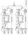
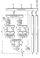
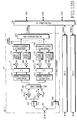
- FIG. 2a and 2b illustrate the construction of a PON employing a multi-carrier CDMA in which the multi-carrier CDMA scheme is applied for an upstream signal transmission according to an embodiment of the present invention.
- a passive optical network (PON) employing a multi-carrier CDMA (Code Division Multiple Access) according to the present invention comprises at least sixteen ONUs (Optical Network Units) or ONTs (Optical Network Terminals) 21 (hereinafter, designated as "ONTs" for the purpose of simplicity) corresponding to the number of subscribers, at least one OLT (Optical Line Terminal) 23 for transmitting optical signals received from the sixteen ONTs 21 into a higher network and for transmitting signals received from the higher network into the ONTs 21, and a 1 ⁇ 16 optical coupler 25 for connecting the sixteen ONTs 21 and the OLT 23.
- ONTs Optical Network Terminals
- Each ONT 21 includes: a first switching means 211, which may be implemented with a hub or any other switch device, connected to a lower interface 27, such as computers; a level transformer 212 for transforming a 100 Mbps Ethernet signal having levels of '0' and '1' into that having levels of '-1' and '+1'; a multiplexer 213 for branching a level-transformed Ethernet signal into sixteen signals; a multiplier 215 for multiplying each of the branched Ethernet signals by each chip 214 of a CDMA code; a multiplier 217 for multiplying the multiplied signals by a plurality of carriers 216; a coupler 218 for coupling the signals having been multiplied by the carriers; a laser driver 219 for controlling a laser drive current; a laser diode 220 for performing optical modulation; an optical receiver (photo diode) 221 for receiving a 1.25 Gbps Ethernet signal transmitted from an OLT; and a WDM (Wavelength Division Multiplexing) filter 222 for dividing up
- the OLT 23 includes: a WDM (Wavelength Division Multiplexing) filter 231 for dividing upstream wavelengths and downstream wavelengths; an optical receiver 232 for receiving an optical signal transmitted from an ONT; a 1 ⁇ 16 branching filter 233 for branching a received upstream signal; a 1 ⁇ 16 re-branching filter 234 for re-branching the branched signals so as to demodulate the signals; a multiplier 236 for multiplying the signals re-branched for signal demodulation by a plurality of carriers 235; a multiplier 238 for multiplying the signals having been multiplied by the carriers 235 by each chip 237 of a CDMA code; a low-pass filter 239 for removing signals in a high frequency band; a coupler 240 for coupling the low-passed signals; data discriminators 241 for discriminating data of the coupled signals; a second switching means 242, which may be implemented with an aggregator or any other switch device, for transforming a 100 Mbps Ethernet signal into
- the OLTs 23 are connected with each other or to a higher network through a switch 29 having a plurality of 1.25 Gbps interfaces.
- data transmitted from a lower interface 27, such as a computer undergoes a switching process or an aggregation process via the first switching means 211, and then are inputted into the level transformer 212 in a form of a 100 Mbps Ethernet signal.
- the level transformer 212 transforms a data signal having levels of '0' and '1' into that having levels of '-1 ' and '+1 '.
- the level-transformed signal is branched into 16 signals through the multiplexer 213, which are then multiplied, in the multiplier 215, by corresponding chips 214 of a specific CDMA code assigned to each ONT 21, respectively. This process will be explained hereinafter with reference to FIG. 3.
- a CDMA code assigned to a j th ONT has 16 chips in a sequence, and each chip is multiplied by signals branched through the multiplexer 213. That is, a first signal of signals branched through the multiplexer 213 is multiplied by a first chip (C1, j) 214 of the CDMA code, a second signal is multiplied by a second chip (C2, j) 214 of the CDMA code, and a sixteenth signal is multiplied by a sixteenth chip (C16, j) 214 of the CDMA code.
- the signals having been multiplied by each corresponding chip of the CDMA code are again multiplied, in the multiplier 217, by carriers 216 having different frequencies from each other. That is, a first signal is multiplied by a carrier having a first frequency f1, a second signal is multiplied by a carrier having a second frequency f2, and a sixteenth signal is multiplied by a carrier having a sixteenth frequency f16.
- the signals having been multiplied by each carrier are coupled in the coupler 218.
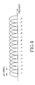
- Frequency spectrums of the coupled signals is shown as FIG. 4.
- 16 frequency spectrums are connected at intervals of 100 MHz (1/Ts), while being overlapped with each other as shown in FIG. 4, in which the 'Ts' is one bit time of a 100 Mbps Ethernet signal to be inputted.
- each spectrum overlapped with other spectrums has a zero crossing at the maximum values of the latter spectrums, so that the orthogonal characteristic among each spectrum can be maintained, thereby preventing an interference problem between received signals.
- the signal coupled by the coupler 218 is converted into laser drive levels in the laser driver 219, and optical-modulated in the laser diode 220 having an upstream wavelength ⁇ UP , and then transmitted to an OLT 23 through the WDM filter 222.
- a 1.25 Gbps Ethernet signal of ⁇ DOWN transmitted downstream from an OLT 23 passes the WDM filter 222, converted into an electric signal in the optical receiver 221, and transmitted to a lower interface 27 through the first switching means 211.
- upstream optical signals of ⁇ UP transmitted from each ONT 21 are coupled in the 1 ⁇ 16 optical coupler 25, and then transmitted to an OLT 23.
- the signal transmitted to the OLT 25 is divided to an optical receiver 232 through a WDM filter 231 in the OLT 23, received in the optical receiver 232, and branched into 16 signals in a 1 ⁇ 16 branching filter 233 so as to detect the respective signals transmitted from 16 number of ONTs 21. Since each of the branched signals includes 16 carriers, each of the branched signals is re-branched into 16 signals in the re-branching filter 234 in order to detect each carrier.
- the re-branched signals are multiplied, in the multiplier 236, by carriers 235 having frequencies of f1 to f16 so as to remove carrier components.
- Each of the multiplied signals is multiplied, in the multiplier 238, by chips 237 of a specific CDMA code assigned to each ONT in the same process as that in the ONT. Since chips of each CDMA code have a perfectly orthogonal characteristic, it is possible to separate each signal transmitted from each ONT 21 through the above-mentioned CDMA-code multiplication process.
- High frequency components are included in the signals multiplied by chips of a CDMA code, so a low-pass filter 239 is used to remove the high frequency components.
- the signals, in which high frequency components are removed, are added in a coupler 240, and 100 Mbps Ethernet data transmitted from each ONT 21 are restored by the data discriminators 241.
- the restored 100 Mbps Ethernet signal is transformed into a 1.25 Gbps Ethernet signal in the second switching means 242, and then transmitted to other OLTs 23 or connected to a higher network through an Ethernet switch 29 connected with a plurality of OLTs 23.
- Ethernet data transmitted from a higher network or another OLT 23 through the Ethernet switch 29 are optical-modulated at an optical transmitter 243 in the OLT 23, pass a WDM filter 231, branched in a 1 ⁇ 16 optical coupler 25, and finally transmitted into ONTs 21.
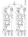
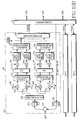
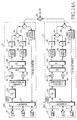
- FIG. 5a and 5b illustrate the construction of a PON employing a multi-carrier CDMA according to another embodiment of the present invention.
- FIG. 5a and 5b shows a construction in which a plurality of carriers 216 and 235 and multipliers 217 and 236 in FIG. 2a and 2b are replaced by an IFFT (Inverse Fast Fourier Transform) block 501 and an FFT (Fast Fourier Transform) block 513.
- IFFT Inverse Fast Fourier Transform
- FFT Fast Fourier Transform
- An ONT 21 shown in FIG. 5a and 5b uses a multiplexer 213 for branching a 100 Mbps Ethernet signal level- transformed by a level transformer 212 into 16 signals, and a multiplier 215 for multiplying the branched signals by a CDMA code 214.
- the ONT 21 includes: an IFFT 501 for performing an inverse Fourier Transform on the multiplied signals; a coupler 502 for performing a parallel/serial conversion on the inverse-Fourier-transformed signals; a multiplier 505 for multiplying 'I' components (real components) by a cosine carrier 503; a multiplier 506 for multiplying 'Q' components (imaginary components) by a sine carrier 504; and an adder 507 for adding the real components and the imaginary components multiplied by carriers through the multipliers 505 and 506.
- the ONT 21 includes a laser driver 219 and a laser diode 220 for performing optical modulation, an optical receiver 221 for receiving a 1.25 Gbps Ethernet signal, and a WDM filter 222.
- an OLT 23 includes: a WDM filter 231; an optical receiver 232; a 1 ⁇ 16 branching filter 233; multipliers 510 and 511 for multiplying received signals by a cosine carrier 508 or a sine carrier 509 so as to divide the received signals into real components and imaginary components; a 1 ⁇ 16 serial/parallel converter 512 for performing a serial/parallel conversion on the divided real components and imaginary components; an FFT 513 for performing a Fourier Transform on the parallel signals converted through the 1 ⁇ 16 serial/parallel converter 512; a multiplier 238 for multiplying the Fourier-transformed signals by a CDMA code 237; a coupler 240 for adding the signals having passed the multiplier 238; a data discriminator 241 for extracting data of the coupled signals; an optical transmitter 243 for transmitting a 1.25 Gbps Ethernet signal in the downstream direction; and a second switching means 242, which may be implemented with an aggregator or any other switch device, for transforming a signal into a 1.25 Gbps
- the OLT 23 includes an Ethernet switch 29 for connecting with other OLTs 23 or a higher network.
- a data signal transmitted from a lower interface 27 passes the first switching means 211, is transformed into a signal having levels of '-1' and '+1' by the level transformer 212, and is branched into 16 signals through the multiplexer 213.
- the branched signals are multiplied by chips 214 of a specific CDMA code assigned according to each ONT 21. A signal conversion process will be explained as follows with reference to FIG 6.
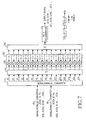
- Table 1 shows a Walsh code table having a 16-chip sequence assigned to sixteen subscribers in the case that the Walsh Hadamard codes are used as CDMA codes. Each code has a perfectly orthogonal characteristic. Chip order c0 c1 c2 c3 c4 c5 c6 c7 c8 c9 c1 c1 c1 c1 c1 Walsh code 0 1 2 3 4 5 Code 1 1 1 1 1 1 1 1 1 1 1 1 1 1 1 1 1 1 1 Code 2 1 -1 1 -1 1 -1 1 -1 1 -1 1 -1 1 -1 1 -1 Code 3 1 1 -1 -1 1 1 1 -1 -1 1 1 1 -1 -1 1 1 1 -1 -1 Code 4 1 -1 -1 1 1 1 -1 -1 1 1 1 -1 -1 1 1 1 -1 -1 1 Code 5 1 1 1 1 1 -1 -1 -1 -1 1 1 1 1 1 -1 -1 -1 1 Code 6 1 -1 1 1 1 1 -1 -1 -1 1 -1 1
- FIG. 6 is an example view illustrating a signal conversion generated in an ONT according to the embodiment shown in FIG. 5a and 5b.
- a CDMA code of '+1 , -1, -1, +1, -1, +1, +1, -1, -1, +1, +1, -1, +1, -1, +1' 64 is assigned according to the Walsh code table shown in Table 1.
- Each chip 214 in the assigned CDMA code is multiplied, in the multiplier 215, by respective signals 62 having been branched by the multiplexer 213.
- X(k) X(k)r + jX(k)i, wherein X(k)r represents a real component and X(k)i represents an imaginary component.
- Signal components outputted through the IFFT 501 are converted by the coupler 502 from a parallel state to a serial state. That is, components X(0) to X(15) inputted in parallel are outputted sequentially in the form of "... X(15), X(14),..., X(0), X(15), X(14),..., X(0), ## 66.
- the real components are multiplied, in the multiplier 505, by a cosine carrier 503 having a frequency of f0, and the imaginary components are multiplied, in the multiplier 506, by a sine carrier 504. Subsequently, the multiplied real components and imaginary components are added in the adder 507.
- the added signal is converted into an optical modulation level in the laser driver 219, converted into an optical signal in the laser diode 220, and transmitted to an OLT 23 through a WDM filter 222.
- upstream optical signals transmitted from each ONT 21 are inputted into an OLT 23 through the 1 ⁇ 16 optical coupler 25, and transmitted to the optical receiver 232 by the WDM filter 231 in the OLT 23.
- the signal converted into an electric signal by the optical receiver 232 is branched into 16 signals in the 1 ⁇ 16 branching filter 233.
- Each of the branched signals is multiplied, in the multiplier 510, by a cosine carrier 508 having a frequency of f0, and also multiplied, in the multiplier 511, by a sine carrier 509 so as to divide each signal into real components and imaginary components.
- real components 65 and imaginary components 66 are detected.
- a process for outputting each signal divided into real components 65 and imaginary components 66 is shown in more detail in FIG. 7.
- the signals divided into real components 65 and imaginary components 66 are converted into parallel components X(0) to X(15) through the serial/parallel converter 512, and then inputted into the FFT 513.
- Fourier-transformed signals through the FFT 513 are multiplied, in the multiplier 238, by each chip 237 in the same assigned CDMA code 64 as in the ONT 21 so as to extract signal components transmitted from each ONT.
- signal components transmitted from each ONT 21 are detected.
- the detected signals are added to each other in the coupler 240, and then transmitted to the data discriminator 241. Thereafter, the data discriminator 241 restores 100 Mbps Ethernet signals transmitted from each ONT.
- the restored 100 Mbps Ethernet signal is transformed into a 1.25 Gbps Ethernet signal in the second switching means 242, and then transmitted to other OLTs 23 or connected to a higher network through an Ethernet switch 29.
- a 1.25 Gbps Ethernet signal transmitted from the Ethernet switch 29 to each ONT 21 is optical-modulated at an optical transmitter 243 in the OLT 23, passes a WDM filter 231 and a 1 ⁇ 16 optical coupler 25, and then transmitted into each ONT 21.
- FIG. 8a and 8b illustrate the construction of a second embodiment modified from the PON employing a multi-carrier CDMA shown in FIG. 5a and 5b according to the present invention.
- multipliers for dividing received signals into real components and imaginary components in an OLT are located at output part of an optical receiver.
- Upstream optical signals transmitted from each ONT 21 are inputted into the OLT 23 through a 1 ⁇ 16 optical coupler 25, and then are transmitted to the optical receiver 232 through the WDM filter 231 in the OLT 23.
- the signal converted into an electric signal by the optical receiver 232 is multiplied, in the multiplier 510, by a cosine carrier 508 having a frequency of f0, and is also multiplied, in the multiplier 511, by a sine carrier 509 so as to divide each signal into real components and imaginary components. Through this process, real components 65 and imaginary components 66 are detected.
- the signals divided into the real component 65 and the imaginary component 66 are respectively branched into 16 signals in the 1 ⁇ 16 branching filter 233.
- Each of the branched real and imaginary signals is converted into parallel components X(0) to X(15) through the serial/parallel converter 512, and then inputted into the FFT 513.
- Fourier-transformed signals through the FFT 513 are multiplied, in the multiplier 238, by chips 237 in the same assigned CDMA code 64 as in the ONT 21 so as to extract signal components transmitted from each ONT 21.
- signal components transmitted from each ONT 21 are detected, and then the detected signals are added in the coupler 240.
- the data discriminator 241 restores the 100 Mbps Ethernet signals transmitted from each ONT.
- the restored 100 Mbps Ethernet signal is transformed into a 1.25 Gbps Ethernet signal in the second switching means 242, and then transmitted to other OLTs 23 or connected to a higher network through an Ethernet switch 29.
- a 1.25 Gbps Ethernet signal transmitted from the Ethernet switch 29 to each ONT 21 is optical-modulated at an optical transmitter 243 in the OLT 23, passes a WDM filter 231 and a 1 ⁇ 16 optical coupler 25, and finally transmitted into each ONT 21.
- FIG. 9a and 9b illustrate the construction of a third embodiment modified from the PON employing a multi-carrier CDMA shown in FIG. 5a and 5b according to the present invention.
- the embodiment shown in FIG. 9a and 9b is characteristic in that real components and imaginary components are both optical-modulated and transmitted, and also the optical-modulated components are received and modulated into electric signals.
- FIG. 9a and 9b is a third embodiment modified from the PON shown in FIG. 5a and 5b, comprises respective laser drivers 91 and 94 and respective laser diodes 92 and 95 in an ONT 21 for each of the real component and the imaginary component so as to optical-modulate each of the signal components, and comprises an optical coupler 93 for coupling the signal components.
- an OLT 23 according to this embodiment comprises an optical branching filter 96 for branching two wavelengths transmitted from the ONT 21, and also comprises optical receivers 97 and 98 for respectively receiving two kinds of optical signals, each of which includes one of the two signal components, branched through the optical branching filter 96.
- the embodiment shown in FIG. 9a and 9b - unlike the embodiment shown in FIG. 5a and 5b in which the ONT 21 and the OLT 23 use cosine carriers, sine carriers, and multipliers so as to divide real components and imaginary components of a transmitted signal - is characteristic in that an optical transmission section 91, 92 and 93 for transmitting real components and an optical transmission section 94, 95 and 93 for transmitting imaginary components are respectively comprised in an ONT 21, and each of the optical transmission sections uses different wavelengths from each other. That is, an optical signal including real components and an optical signal including imaginary components are coupled in an optical coupler 93 and transmitted to the OLT 23.
- an upstream signal passes an optical branching filter 96 and inputted into optical receivers 97 and 98.
- the OLT 23 is characteristic of comprising the optical receiver 97 for detecting real components and the optical receiver 98 for detecting imaginary components, respectively.
- each of electrically-different real and imaginary components is modulated into an optical signal, the two modulated optical signals are added to each other, and the added optical signal is transmitted; while in the embodiment shown in FIG. 5a and 5b, electrically added real and imaginary components are first transmitted as an optical signal, and a received optical signal is divided into the real component and the imaginary component.
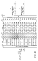
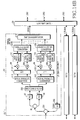
- FIG. 10a and 10b illustrate the construction of a fourth embodiment modified from the PON employing a multi-carrier CDMA shown in FIG. 5a and 5b according to the present invention.
- a 100 Mbps Ethernet signal level-transformed by a level transformer 212 is converted into parallel signals by a serial/parallel converter 100 which converts a serial signal into a parallel signal.
- a multiplier 215 is used to multiply the parallel signals by a CDMA code 64.
- the ONT 21 includes: an IFFT 501 for performing an inverse Fourier Transform on the multiplied signals; a coupler 502 for performing a parallel/serial conversion on the inverse-Fourier-transformed signals; a multiplier 505 for multiplying 'I' components (real components) by a cosine carrier 503; a multiplier 506 for multiplying 'Q' components (imaginary components) by a sine carrier 504; and an adder 507 for adding the real components and the imaginary components multiplied by carriers through the multipliers 505 and 506.
- the ONT 21 includes a laser driver 219 and a laser diode 220 for performing optical modulation, an optical receiver 221 for receiving a 1.25 Gbps Ethernet signal, and a WDM filter 222.
- an OLT 23 includes: a WDM filter 231; an optical receiver 232; a 1 ⁇ 16 branching filter 233; multipliers 510 and 511 for multiplying received signals by a cosine carrier 508 or a sine carrier 509 so as to divide the received signals into real components and imaginary components; a 1 ⁇ 16 serial/parallel converter 512 for performing a serial/parallel conversion on the divided real components and imaginary components; an FFT 513 for performing a Fourier Transform on the parallel signals converted through the 1 ⁇ 16 serial/parallel converter 512; a multiplier 238 for multiplying the Fourier-transformed signals by a CDMA code 64; data discriminators 110 for extracting data from each parallel signal outputted through the multiplier 238; a parallel/serial converter 120 for converting a parallel signal into a serial signal; and a second switching means 242, which may be implemented with an aggregator or any other switch device, for transforming a signal into a 1.25 Gbps Ethernet signal. Also, the OLT 23 includes an optical transmitter
- the OLT 23 includes an Ethernet switch 29 for connecting with other OLTs 23 or a higher network.
- the operation principle of the Ethernet PON shown in FIG. 10a and 10b according to the present invention is as follows. Particularly, in order to make the signal flow clear, the following description will be given with reference to FIGS. 11 and 12.
- a data signal transmitted from a lower interface 27 passes the first switching means 211, is transformed into a signal having levels of '-1' and '+1' in the level transformer 212.
- a 100 Mbps Ethernet signal 1100 which is transformed into a signal having levels of '-1' and '+1', is branched into 16 parallel signals in the 1 ⁇ 16 serial/parallel converter 100.
- a signal inputted as a reference number '1100' is converted into parallel signals as shown as a reference number '1200' by the serial/parallel converter 100.
- one-bit duration time of the parallel-converted signal is sixteen times as long as one-bit duration time of the serial signal.
- a signal of each bit, which is converted into parallel signals, is multiplied, in the multiplier 215, by a specific CDMA code assigned according to ONTs 21.
- a 16-chip CDMA code of '+1, -1, -1, +1, -1, +1, +1, -1, -1, +1, +1, -1, +1, -1, +1' 64 is assigned as shown in Table 1.
- a chip rate is 100 Mcps, which is sixteen times as fast as a parallel signal speed.
- embodiments shown in FIG. 10a, 10b, and following drawings have a distinctive feature as compared to the embodiments of FIG. 5 to 9, in that all 16 chips of a CDMA code 64 are multiplied in the multiplier 215 in the case of embodiments of FIG. 10a, 10b and following drawings, while a corresponding chip 214 of a 16-chip CDMA code 64 is multiplied in the multiplier 215 in the case of embodiment of FIG. 5 to 9.
- each of parallel-converted signals 1200 is directly multiplied by all of an assigned CDMA code 64.
- CDMA code 64 As a result of this, spread spectrum signals of reference number '1300' can be obtained.
- the signals multiplied by the CDMA code 64 undergo an inverse Fourier transform in the IFFT 501 and transmitted to an OLT 23 through the same process as that described in the embodiment of FIG. 5a and 5b.
- an upstream signal is divided by the WDM filter 231, thereby being received into the optical receiver 232.
- the received signal is branched into 16 signals through the branching filter 233, and each of the branched signals is divided into real components and imaginary components through the same process as that described in the embodiment of FIG. 5a and 5b.
- the divided real components 65 and imaginary components 66 are divided into parallel signals in the serial/parallel converter 512, and undergo a Fourier transform in the FFT 513.
- Each of the Fourier-transformed signals is multiplied, in the multiplier 238, by respective CDMA codes so as to detect signals transmitted from each ONT 21.
- the Fourier-transformed signal is multiplied by the CDMA code 64 (Code 16).
- data transmitted from the ONT 21 are restored from the respective parallel signal components multiplied by the CDMA code 64, while having the same signal form as that represented as reference number '1200'. Subsequently, the restored data are converted into 100 Mbps Ethernet signals (output signals) through the parallel/serial converter 120, and then undergo the same process as that described in the embodiment of FIG. 5a and 5b.
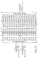
- FIG. 13a and 13b illustrate the construction of a second embodiment modified from the PON employing a multi-carrier CDMA shown in FIG. 10a and 10b according to the present invention.
- multipliers for dividing received signals into real components and imaginary components in an OLT are located at output part of an optical receiver.
- Upstream optical signals transmitted from each ONT 21 are inputted into the OLT 23 through the 1 ⁇ 16 optical coupler 25 and transmitted to the optical receiver 232 by the WDM filter 231 in the OLT 23.
- the signal converted into an electric signal by the optical receiver 232 is multiplied, in the multiplier 510, by a cosine carrier 508 having a frequency of f0, and is also multiplied, in the multiplier 511, by a sine carrier 509 so as to divide each signal into real components and imaginary components.
- real components 65 and imaginary components 66 are detected.
- the signals divided into the real component 65 and the imaginary component 66 are respectively branched into 16 signals in the 1 ⁇ 16 branching filter 233.
- Each of the branched real and imaginary signals is converted into parallel components X(0) to X(15) through the serial/parallel converter 512 and inputted into the FFT 513.
- Fourier-transformed signals through the FFT 513 are multiplied, in the multiplier 238, by the same assigned CDMA code 64 as in a corresponding ONT 21 so as to extract signal components transmitted from each ONT 21.
- signal components transmitted from each ONT 21 are detected.
- 100 Mbps Ethernet signals transmitted from each ONT are restored in parallel by the data discriminator 110. Subsequently, all of the 100 Mbps Ethernet signals are outputted through the parallel/serial converter 120.
- the restored 100 Mbps Ethernet signal is transformed into a 1.25 Gbps Ethernet signal in the second switching means 242 and transmitted to other OLTs 23 or connected to a higher network through an Ethernet switch 29.
- a 1.25 Gbps Ethernet signal transmitted from the Ethernet switch 29 to each ONT 21 is optical-modulated at an optical transmitter 243 in the OLT 23, passes a WDM filter 231 and a 1 ⁇ 16 optical coupler 25, and transmitted into each ONT 21.
- FIG. 14a and 14b illustrate the construction of a third embodiment modified from the PON employing a multi-carrier CDMA shown in FIG. 10a and 10b according to the present invention.
- the embodiment shown in FIG. 14a and 14b is characteristic in that real components and imaginary components are respectively optical-modulated and transmitted, and also the optical-modulated components are received and modulated into electric signals.
- FIG. 14a and 14b is a third embodiment modified from the PON employing a multi-carrier CDMA shown in FIG. 10a and 10b, comprises respective laser drivers 91 and 94 and respective laser diodes 92 and 95 in an ONT 21 for each of the real component and the imaginary component so as to optical-modulate each of the signal components, and further comprises an optical coupler 93 for coupling the signal components.
- an OLT 23 according to this embodiment comprises an optical branching filter 96 for branching two wavelengths transmitted from the ONT 21, and also comprises optical receivers 97 and 98 for respectively receiving two kinds of optical signals, each of which includes one of the signal components, branched through the optical branching filter 96.
- the embodiment shown in FIG. 14a and 14b - unlike the embodiment shown in FIG. 10a and 10b in which the ONT 21 and the OLT 23 use cosine carriers, sine carriers, and multipliers so as to divide real components and imaginary components of a transmitted signal - is characteristic in that an optical transmission section 91, 92 and 93 for transmitting real components and an optical transmission section 94, 95 and 93 for transmitting imaginary components are respectively comprised in an ONT 21, and each of the optical transmission sections uses different wavelengths from each other. That is, an optical signal including real components and an optical signal including imaginary components are coupled in an optical coupler 93, and are transmitted to the OLT 23.
- an upstream signal passes an optical branching filter 96 and inputted into optical receivers 97 and 98.
- the OLT 23 is characteristic of comprising an optical receiver 97 for detecting real components and an optical receiver 98 for detecting imaginary components respectively.
- each of electrically-different real and imaginary components is modulated into an optical signal, the two modulated optical signals are added to each other, and the added optical signal is transmitted; in the embodiment shown in FIG. 10a and 10b, electrically added real and imaginary components are first transmitted as an optical signal, and a received optical signal is divided into the real component and the imaginary component.
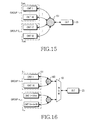
- FIG. 15 is a construction view illustrating a PON for accommodating 32 subscribers.
- the embodiment shown in FIG. 15 comprises 32 number of ONTs 21, an OLT 23, and a 1 ⁇ 32 optical coupler 151.
- the ONTs 21 are classified into two groups and use different wavelengths from each other according to groups.
- the detailed construction and operation of the ONT 21 and the OLT 23 are identical to those described above, thus not explained to avoid redundancy.
- FIG. 16 is a construction view in which a PON according to the present invention is connected with a WDM-PON, and includes ONT groups 161 using different wavelengths from each other, an OLT 23, a wavelength multiplexing/demultiplexing device 162, and optical couplers 163.
- Each of the ONT groups 161 comprises sixteen ONTs.
- the OLT 23 comprises CDMA-receipt blocks for receiving signals according to wavelengths.
- the PON according to the present invention unlike the conventional PON, adopts the CDMA method as an upstream transmission method, so that it is not necessary to use the complicated MAC protocol requested as in prior art. Therefore, the PON according to the present invention enables the ONTs to maintain a state capable of transmitting data at all times, thereby guaranteeing a wide upstream transmission bandwidth of 100 Mbps at all times, unlike the prior art.
- the PON according to the present invention employs a multi-carrier CDMA, only a simple electronic circuit capable of handling about 100 Mbps of data is required. Therefore, the PON according to the present invention has effects of simplifying complicated signal processes in a transmitter and a receiver and efficiently solving a synchronization problem.
- the PON according to the present invention can henceforth be efficiently applied to large-scale subscriber networks and can be excellently applied to WDM-PONs generally recognized as an ideal structure for optical subscriber network.
Landscapes
- Engineering & Computer Science (AREA)
- Computer Networks & Wireless Communication (AREA)
- Signal Processing (AREA)
- Physics & Mathematics (AREA)
- Optics & Photonics (AREA)
- Electromagnetism (AREA)
- Optical Communication System (AREA)
- Small-Scale Networks (AREA)
- Digital Transmission Methods That Use Modulated Carrier Waves (AREA)
Applications Claiming Priority (2)
| Application Number | Priority Date | Filing Date | Title |
|---|---|---|---|
| KR2003028716 | 2003-05-06 | ||
| KR10-2003-0028716A KR100539926B1 (ko) | 2003-05-06 | 2003-05-06 | 다중 반송파를 이용한 코드 분할 다중화 방식의 수동형 광가입자망 |
Publications (2)
| Publication Number | Publication Date |
|---|---|
| EP1475915A2 true EP1475915A2 (de) | 2004-11-10 |
| EP1475915A3 EP1475915A3 (de) | 2009-06-17 |
Family
ID=32985959
Family Applications (1)
| Application Number | Title | Priority Date | Filing Date |
|---|---|---|---|
| EP20040007858 Withdrawn EP1475915A3 (de) | 2003-05-06 | 2004-03-31 | Passives optisches Netzwerk mit Mehrträger CDMA |
Country Status (4)
| Country | Link |
|---|---|
| US (1) | US7272318B2 (de) |
| EP (1) | EP1475915A3 (de) |
| JP (1) | JP3996910B2 (de) |
| KR (1) | KR100539926B1 (de) |
Cited By (6)
| Publication number | Priority date | Publication date | Assignee | Title |
|---|---|---|---|---|
| EP2104250A1 (de) * | 2008-03-18 | 2009-09-23 | Alcatel Lucent | Überwachungsverfahren für ein passives optisches Netzwerk |
| CN101902666A (zh) * | 2010-04-23 | 2010-12-01 | 中兴通讯股份有限公司 | 光码分多址无源光网络系统、光分配网装置及光线路终端 |
| EP1998481A3 (de) * | 2007-05-31 | 2011-01-19 | Oki Electric Industry Co., Ltd. | Passives optisches Netzwerkkommunikationsverfahren und -system |
| CN101719794B (zh) * | 2009-11-27 | 2012-05-16 | 上海交通大学 | 混合无源光网络系统及其传输方法 |
| CN101719803B (zh) * | 2009-11-27 | 2013-01-09 | 上海交通大学 | 波分复用无源光网络中的副载波组播传输系统 |
| CN104159170A (zh) * | 2014-08-04 | 2014-11-19 | 武汉光盈科技有限公司 | 适用于光信号标记及解析装置、光信号标记及解析方法 |
Families Citing this family (13)
| Publication number | Priority date | Publication date | Assignee | Title |
|---|---|---|---|---|
| KR100594096B1 (ko) * | 2003-07-30 | 2006-07-03 | 삼성전자주식회사 | 통신/방송 융합 ftth에서의 가입자 정합 장치 |
| JP4561403B2 (ja) * | 2005-02-25 | 2010-10-13 | 沖電気工業株式会社 | 光分割多重送受信方法及び光分割多重送受信装置 |
| US7983562B1 (en) * | 2005-06-30 | 2011-07-19 | Hrl Laboratories, Llc | Dynamic coding for optical code-division multiple access |
| US8023823B2 (en) * | 2005-10-20 | 2011-09-20 | Fujitsu Limited | System and method for transmitting upstream traffic in an optical network |
| US7903973B1 (en) * | 2005-12-23 | 2011-03-08 | Lockheed Martin Corporation | Dynamic temporal duration optical transmission privacy |
| JP2007243545A (ja) * | 2006-03-08 | 2007-09-20 | Nec Corp | 多重化スイッチング回路及び多重化スイッチング方法 |
| US8280253B2 (en) * | 2006-06-30 | 2012-10-02 | France Telecom | Optical telecommunications network terminal, an installation including the terminal, and a method of detecting a break in optical transmission means |
| US8374504B2 (en) * | 2006-10-06 | 2013-02-12 | Hitachi, Ltd. | Optical communication system |
| JP4839266B2 (ja) * | 2007-06-07 | 2011-12-21 | 株式会社日立製作所 | 光通信システム |
| JP5486179B2 (ja) * | 2008-11-25 | 2014-05-07 | 三星電子株式会社 | 送信装置、受信装置、信号送信方法、及び信号受信方法 |
| US20140355989A1 (en) * | 2010-05-17 | 2014-12-04 | Cox Communications, Inc. | Systems and methods for providing broadband communication |
| EP2730042A1 (de) * | 2011-07-08 | 2014-05-14 | Telefonaktiebolaget L M Ericsson (publ) | Optisches zugangsnetz |
| US11095364B2 (en) * | 2019-03-04 | 2021-08-17 | Infiriera Corporation | Frequency division multiple access optical subcarriers |
Family Cites Families (8)
| Publication number | Priority date | Publication date | Assignee | Title |
|---|---|---|---|---|
| JP4586305B2 (ja) * | 2001-06-18 | 2010-11-24 | 沖電気工業株式会社 | 多重化光伝送方法及び多重化光伝送装置 |
| US6925263B2 (en) * | 2001-09-28 | 2005-08-02 | Intel Corporation | Method and apparatus for transmission of upstream data in an optical network |
| US6697374B1 (en) * | 2001-12-05 | 2004-02-24 | Flexlight Networks | Optical network communication system |
| KR100421151B1 (ko) * | 2002-01-17 | 2004-03-04 | 삼성전자주식회사 | 기가비트 이더넷 수동 광 가입자 망 시스템에서의 동작구현방법 및 그 이더넷 프레임 구조 |
| US20040105434A1 (en) * | 2002-08-19 | 2004-06-03 | Allan Baw | EtherCell |
| US6785558B1 (en) * | 2002-12-06 | 2004-08-31 | Lgc Wireless, Inc. | System and method for distributing wireless communication signals over metropolitan telecommunication networks |
| JP4419391B2 (ja) | 2003-01-09 | 2010-02-24 | 沖電気工業株式会社 | 伝送媒体アクセス制御システムおよび中継側ターミナル装置 |
| US7830879B2 (en) * | 2003-12-24 | 2010-11-09 | Agere Systems Inc. | Network-based data distribution system |
-
2003
- 2003-05-06 KR KR10-2003-0028716A patent/KR100539926B1/ko not_active Expired - Fee Related
-
2004
- 2004-02-02 US US10/770,370 patent/US7272318B2/en not_active Expired - Fee Related
- 2004-03-31 EP EP20040007858 patent/EP1475915A3/de not_active Withdrawn
- 2004-05-06 JP JP2004137011A patent/JP3996910B2/ja not_active Expired - Fee Related
Cited By (10)
| Publication number | Priority date | Publication date | Assignee | Title |
|---|---|---|---|---|
| EP1998481A3 (de) * | 2007-05-31 | 2011-01-19 | Oki Electric Industry Co., Ltd. | Passives optisches Netzwerkkommunikationsverfahren und -system |
| US8014675B2 (en) | 2007-05-31 | 2011-09-06 | Oki Electric Industry Co., Ltd. | Passive optical network communication method and system |
| EP2104250A1 (de) * | 2008-03-18 | 2009-09-23 | Alcatel Lucent | Überwachungsverfahren für ein passives optisches Netzwerk |
| WO2009115421A1 (en) * | 2008-03-18 | 2009-09-24 | Alcatel Lucent | Monitoring method for a passive optical network |
| US8625987B2 (en) | 2008-03-18 | 2014-01-07 | Alcatel Lucent | Monitoring method for a passive optical network |
| CN101719794B (zh) * | 2009-11-27 | 2012-05-16 | 上海交通大学 | 混合无源光网络系统及其传输方法 |
| CN101719803B (zh) * | 2009-11-27 | 2013-01-09 | 上海交通大学 | 波分复用无源光网络中的副载波组播传输系统 |
| CN101902666A (zh) * | 2010-04-23 | 2010-12-01 | 中兴通讯股份有限公司 | 光码分多址无源光网络系统、光分配网装置及光线路终端 |
| WO2011130995A1 (zh) * | 2010-04-23 | 2011-10-27 | 中兴通讯股份有限公司 | 光码分多址无源光网络系统、光分配网装置及光线路终端 |
| CN104159170A (zh) * | 2014-08-04 | 2014-11-19 | 武汉光盈科技有限公司 | 适用于光信号标记及解析装置、光信号标记及解析方法 |
Also Published As
| Publication number | Publication date |
|---|---|
| US20040223763A1 (en) | 2004-11-11 |
| KR20040095107A (ko) | 2004-11-12 |
| JP2004336784A (ja) | 2004-11-25 |
| US7272318B2 (en) | 2007-09-18 |
| EP1475915A3 (de) | 2009-06-17 |
| JP3996910B2 (ja) | 2007-10-24 |
| KR100539926B1 (ko) | 2005-12-28 |
Similar Documents
| Publication | Publication Date | Title |
|---|---|---|
| US7330656B2 (en) | Passive optical network employing code division multiple access | |
| US7272318B2 (en) | Passive optical network employing multi-carrier code division multiple access | |
| EP2924896B1 (de) | Sende-/empfangs- und kommunikationssystem sowie signalmodulationsverfahren für ein glasfasernetzwerk | |
| US8229007B2 (en) | High bandwidth data transport system | |
| Qian et al. | 10-Gb/s OFDMA-PON for delivery of heterogeneous services | |
| EP2156591A2 (de) | Docsis-kompatible pon-architektur | |
| Obite et al. | The evolution of ethernet passive optical network (EPON) and future trends | |
| US20150319028A1 (en) | Preamble design and detection for ranging in an optical ofdma communication network | |
| CN1084987C (zh) | 混合光纤/同轴电缆视频和电话通信系统 | |
| KR100872214B1 (ko) | 수동형 광 네트워크 시스템의 광 가입자 종단 장치 및방송/이더넷 데이터 전송 방법 | |
| KR100541062B1 (ko) | 파장공유된 wdm-scma 수동형 광가입자망 | |
| CN106788766B (zh) | 一种基于开关键控光调制的ofdm-pon系统 | |
| EP2777178B1 (de) | Verfahren und vorrichtung zur raman-übersprechungs-abschwächung | |
| CN103117831A (zh) | 一种无源光网络系统的上行信道接入装置 | |
| CN103347222A (zh) | Ofdm-pon中实现onu无色化的方法和系统 | |
| CN103873410B (zh) | Ofdm-pon系统及时钟信号的发送和提取方法 | |
| CN1129870A (zh) | 改进的副载波多址连接无源光网络 | |
| Zhang et al. | Investigation on performance of passive optical network based on OCDMA | |
| CA2538621A1 (en) | Broadband communications | |
| US20070147838A1 (en) | Optical transmission apparatus and optical access network for wavelength-division multiplexing optical network with both sub-carrier multiplex and sub-carrier multiple access schemes | |
| Karbassian | Design and analysis of spreading code and transceiver architectures for optical CDMA networks | |
| CN120342539A (zh) | 一种信号传输设备、信号传输方法、系统及存储介质 | |
| Koonen | Optical network architectures |
Legal Events
| Date | Code | Title | Description |
|---|---|---|---|
| PUAI | Public reference made under article 153(3) epc to a published international application that has entered the european phase |
Free format text: ORIGINAL CODE: 0009012 |
|
| 17P | Request for examination filed |
Effective date: 20040331 |
|
| AK | Designated contracting states |
Kind code of ref document: A2 Designated state(s): AT BE BG CH CY CZ DE DK EE ES FI FR GB GR HU IE IT LI LU MC NL PL PT RO SE SI SK TR |
|
| AX | Request for extension of the european patent |
Extension state: AL LT LV MK |
|
| PUAL | Search report despatched |
Free format text: ORIGINAL CODE: 0009013 |
|
| AK | Designated contracting states |
Kind code of ref document: A3 Designated state(s): AT BE BG CH CY CZ DE DK EE ES FI FR GB GR HU IE IT LI LU MC NL PL PT RO SE SI SK TR |
|
| AX | Request for extension of the european patent |
Extension state: AL LT LV MK |
|
| 17Q | First examination report despatched |
Effective date: 20090825 |
|
| AKX | Designation fees paid |
Designated state(s): DE FR GB |
|
| STAA | Information on the status of an ep patent application or granted ep patent |
Free format text: STATUS: THE APPLICATION IS DEEMED TO BE WITHDRAWN |
|
| 18D | Application deemed to be withdrawn |
Effective date: 20100105 |