EP1475877A2 - Procédé de commande pour d'un reseau de bord de vehicule - Google Patents
Procédé de commande pour d'un reseau de bord de vehicule Download PDFInfo
- Publication number
- EP1475877A2 EP1475877A2 EP04005265A EP04005265A EP1475877A2 EP 1475877 A2 EP1475877 A2 EP 1475877A2 EP 04005265 A EP04005265 A EP 04005265A EP 04005265 A EP04005265 A EP 04005265A EP 1475877 A2 EP1475877 A2 EP 1475877A2
- Authority
- EP
- European Patent Office
- Prior art keywords
- electrical system
- emergency power
- power battery
- generator
- vehicle
- Prior art date
- Legal status (The legal status is an assumption and is not a legal conclusion. Google has not performed a legal analysis and makes no representation as to the accuracy of the status listed.)
- Granted
Links
Images
Classifications
-
- H—ELECTRICITY
- H02—GENERATION; CONVERSION OR DISTRIBUTION OF ELECTRIC POWER
- H02J—CIRCUIT ARRANGEMENTS OR SYSTEMS FOR SUPPLYING OR DISTRIBUTING ELECTRIC POWER; SYSTEMS FOR STORING ELECTRIC ENERGY
- H02J7/00—Circuit arrangements for charging or depolarising batteries or for supplying loads from batteries
- H02J7/14—Circuit arrangements for charging or depolarising batteries or for supplying loads from batteries for charging batteries from dynamo-electric generators driven at varying speed, e.g. on vehicle
- H02J7/1423—Circuit arrangements for charging or depolarising batteries or for supplying loads from batteries for charging batteries from dynamo-electric generators driven at varying speed, e.g. on vehicle with multiple batteries
-
- Y—GENERAL TAGGING OF NEW TECHNOLOGICAL DEVELOPMENTS; GENERAL TAGGING OF CROSS-SECTIONAL TECHNOLOGIES SPANNING OVER SEVERAL SECTIONS OF THE IPC; TECHNICAL SUBJECTS COVERED BY FORMER USPC CROSS-REFERENCE ART COLLECTIONS [XRACs] AND DIGESTS
- Y02—TECHNOLOGIES OR APPLICATIONS FOR MITIGATION OR ADAPTATION AGAINST CLIMATE CHANGE
- Y02T—CLIMATE CHANGE MITIGATION TECHNOLOGIES RELATED TO TRANSPORTATION
- Y02T10/00—Road transport of goods or passengers
- Y02T10/60—Other road transportation technologies with climate change mitigation effect
- Y02T10/70—Energy storage systems for electromobility, e.g. batteries
Definitions
- the invention relates to a method for controlling the electrical system of a motor vehicle according to the preamble of claim 1, as is known from DE 100 33 317 A1.
- safety-relevant consumers e.g. electrohydraulic brakes, occupant restraint systems or the like
- the importance of reliable electrical energy supply to the consumers increases due to the on-board electrical system of the motor vehicle having at least one motor vehicle battery powered by a generator.
- conventional motor vehicle batteries vehicle electrical system batteries
- emergency power batteries for energy supply are particularly common for the safety-relevant consumers of the motor vehicle.
- the emergency power battery can be coupled to the vehicle electrical system using suitable switching elements such as semiconductor switches or relays.
- the high dynamics in the energy supply required by many safety-relevant consumers of the motor vehicle can only be achieved with great difficulty and high costs with the generic method when using the emergency power battery.
- the invention has for its object to provide a method for controlling the electrical system of a motor vehicle according to the preamble of claim 1, in which a reliable power supply to the consumers of the motor vehicle is provided in a simple manner at low cost. This object is achieved by the characterizing part of patent claim 1. Advantageous embodiments of the invention form part of the further claims.
- the emergency power battery is connected to the vehicle electrical system of the motor vehicle as required, ie depending on the current degree of utilization of the generator (the degree of utilization of the generator is determined here by the percentage ratio between the power consumption of the consumers connected to the vehicle electrical system and the current performance of the generator) and the operating mode of the vehicle electrical system, which is dependent on the voltage state of the vehicle electrical system.
- the degree of utilization of the generator is determined here by the percentage ratio between the power consumption of the consumers connected to the vehicle electrical system and the current performance of the generator
- the operating mode of the vehicle electrical system which is dependent on the voltage state of the vehicle electrical system.
- the emergency power battery is always switched on to the on-board electrical system regardless of the voltage state of the on-board electrical system and thus regardless of the operating mode of the on-board electrical system, i.e. both in normal operation with normal voltage state in the on-board electrical system (buffering the on-board electrical system connected consumers possible by the motor vehicle battery), as well as in emergency operation in the event of an undervoltage in the vehicle electrical system (this is caused, for example, by a failure or a defect in the motor vehicle battery) when the consumers integrated in the vehicle electrical system are supplied by the emergency power battery. If the threshold for the degree of utilization of the generator is exceeded, i.e.
- the emergency power battery is only switched on to the on-board electrical system depending on the voltage state of the on-board electrical system and therefore depending on the operating mode in the event of an undervoltage in the on-board electrical system (only in emergency mode), while the emergency power battery is connected to the on-board electrical system is not switched on in normal voltage state (in normal operation).
- the undervoltage of the on-board electrical system ie as a criterion for the transition from normal operation to emergency operation, is used to fall below a certain voltage value for the voltage in the on-board electrical system.
- the threshold value for the degree of utilization of the generator is selected as a function of the size of the generator and depending on the consumers to be supplied, in particular depending on the safety-relevant consumers to be supplied, for example.
- the threshold is determined at a load factor of the generator of 75%.
- the connection of the emergency power battery to the vehicle electrical system (and also the disconnection of the emergency power battery from the vehicle electrical system) is carried out using a suitable switching element, e.g. via a relay.
- the voltage of the emergency battery can be monitored to diagnose the performance of the emergency battery.
- a consumer with defined properties can be connected to the emergency power battery, e.g. via a relay.
- the control of the on-board electrical system (evaluation of the voltage state in the on-board electrical system, connection of the emergency power battery to the on-board electrical system and disconnection of the emergency power battery from the on-board electrical system by controlling suitable switching elements, diagnosis of the state or performance of the emergency power battery) can be carried out via a device provided in the motor vehicle (in particular via an in-vehicle electrical system) integrated) control unit, in particular via a control unit for battery energy management.
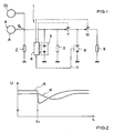
- a motor vehicle battery 5 fed by a generator 4 with a constant output power P A is provided in the electrical system 1 of a motor vehicle for the electrical energy supply of the consumers 2, 3, for example to supply the conventional consumer 2 of the motor vehicle and the example.
- Safety-relevant consumer 3 of the motor vehicle designed as an electrohydraulic brake.
- the emergency power battery 6 is provided, which is used in particular to supply power to the safety-relevant consumer 3.
- the starter 11 connected to the vehicle electrical system 1 and the generator 4 is provided for starting the motor vehicle.
- the control of the on-board electrical system 1, in particular the connection of the emergency battery 6 to the on-board electrical system 1 by means of the switching element 7, is controlled by the control unit 8 responsible for battery energy management of the motor vehicle as a function of the degree of utilization A of the generator 4, i.e. as a function of the percentage ratio of the power requirement Consumers 2, 3 in the vehicle electrical system 1 at the constant output power P A that can currently be output by the generator 4.
- the control unit 8 responsible for battery energy management of the motor vehicle as a function of the degree of utilization A of the generator 4, i.e. as a function of the percentage ratio of the power requirement Consumers 2, 3 in the vehicle electrical system 1 at the constant output power P A that can currently be output by the generator 4.
- Switching element 7 designed as a coupling relay is always closed, ie both in normal operation when the consumers 2, 3 are supplied by the motor vehicle battery 5 and in emergency operation when the consumers 2, 3 are supplied by the emergency power battery 6; the emergency power battery 6 is therefore permanently charged via the generator 4 at a low degree of utilization A of the generator 4. If, in the event of a defect in the motor vehicle battery 5, the vehicle electrical system 1 is connected to a further consumer (time t1 in FIG. 2), in particular if a high-current consumer is connected to the vehicle electrical system 1, the voltage U in the vehicle electrical system 1, in particular for the safety-relevant consumer 3, can achieve the required minimum voltage be held in the electrical system 1 via the emergency battery 6 (see curve (a) in FIG. 2).
- a certain threshold value of the degree of utilization A of the generator 4 e.g. if a degree of utilization A of the generator 4 of 75% is exceeded, ie if the degree of utilization of the generator 4 is high, the example is.
- Switching element 7 designed as a coupling relay is opened in normal operation; since the motor vehicle battery 5 alone buffers the vehicle electrical system 1, the emergency power battery 6 is protected. If, in the event of a defect in the motor vehicle battery 5, the vehicle electrical system 1 is connected to a further consumer (time t1 in FIG. 2), in particular if a high-current consumer is connected to the vehicle electrical system 1, sufficient energy is already stored in the vehicle electrical system 1, so that brief peaks in the power requirement via the vehicle electrical system 1 can be buffered.
- the voltage U in the on-board electrical system 1 drops slowly enough due to this buffer effect when the generator 4 is under high load (see curve (b) in FIG. 2) in order to connect the emergency power battery 6 to the on-board electrical system 1 via the coupling relay 7 in emergency operation and accordingly to buffer the safety-relevant one Use consumer 3.
- the voltage of the emergency power battery 6 can be detected and monitored in all phases in which the switching element 7 is not closed (the coupling relay 7 is not activated);
- the connection 11 between the emergency power battery 6 and the control unit 8 is provided.
- the example can improve the diagnostic possibility for the emergency power battery 6 can by the example.
- Switching element 10 designed as a relay a defined consumer 9 can be switched to test battery 6 as test consumer, so that, for example, A statement about the performance of the emergency power battery 6 can be made by means of characteristic fields; E.g. For example, information (for example, as a visual warning display or as an acoustic warning signal) is provided when the temperature drops below a certain predetermined minimum voltage as a function of the temperature.
- the control unit 8 responsible for battery energy management of the motor vehicle can also take over the control of the switching element (relay) 10 and the diagnosis of the emergency power battery 6.
Applications Claiming Priority (2)
| Application Number | Priority Date | Filing Date | Title |
|---|---|---|---|
| DE10320952A DE10320952B4 (de) | 2003-05-09 | 2003-05-09 | Verfahren zur Ansteuerung des Bordnetzes eines Kraftfahrzeuges |
| DE10320952 | 2003-05-09 |
Publications (3)
| Publication Number | Publication Date |
|---|---|
| EP1475877A2 true EP1475877A2 (fr) | 2004-11-10 |
| EP1475877A3 EP1475877A3 (fr) | 2005-06-15 |
| EP1475877B1 EP1475877B1 (fr) | 2009-06-03 |
Family
ID=32981315
Family Applications (1)
| Application Number | Title | Priority Date | Filing Date |
|---|---|---|---|
| EP04005265A Expired - Fee Related EP1475877B1 (fr) | 2003-05-09 | 2004-03-05 | Procédé de commande d'un réseau de bord de vehicule |
Country Status (2)
| Country | Link |
|---|---|
| EP (1) | EP1475877B1 (fr) |
| DE (2) | DE10320952B4 (fr) |
Cited By (2)
| Publication number | Priority date | Publication date | Assignee | Title |
|---|---|---|---|---|
| FR2990306A1 (fr) * | 2012-05-04 | 2013-11-08 | Peugeot Citroen Automobiles Sa | Procede de pilotage d'un convertisseur de puissance d'un stockeur de secours dans un vehicule automobile |
| CN114123650A (zh) * | 2020-08-28 | 2022-03-01 | 克诺尔商用车制动系统有限公司 | 供能装置、用于给至少一个电气负载供电的方法以及车辆 |
Families Citing this family (3)
| Publication number | Priority date | Publication date | Assignee | Title |
|---|---|---|---|---|
| DE102006061137A1 (de) * | 2006-12-22 | 2008-06-26 | Siemens Ag | Steuereinheit zur Steuerung mindestens eines Verbrauchers |
| DE102007059684A1 (de) | 2007-12-12 | 2009-06-25 | Lucas Automotive Gmbh | Elektronisches System zum Betreiben einer elektromechanischen Parkbremse |
| DE102013002500A1 (de) * | 2013-02-13 | 2014-08-14 | Volkswagen Aktiengesellschaft | Bremsassistenzsystem für ein Fahrzeug |
Citations (3)
| Publication number | Priority date | Publication date | Assignee | Title |
|---|---|---|---|---|
| US5583440A (en) * | 1992-02-24 | 1996-12-10 | Bisher; Roger C. | Method and apparatus for testing an auxiliary power system |
| US6049141A (en) * | 1997-05-21 | 2000-04-11 | Aer Energy Resources, Inc. | Device and a method allowing multiple batteries to share a common load |
| DE10033317A1 (de) * | 2000-06-29 | 2002-01-10 | Volkswagen Ag | Kraftfahrzeugbordnetz mit sicherheitsrelevanten Verbrauchern |
Family Cites Families (1)
| Publication number | Priority date | Publication date | Assignee | Title |
|---|---|---|---|---|
| DE10020141B4 (de) * | 2000-04-17 | 2009-02-19 | Volkswagen Ag | Bordnetzsystem |
-
2003
- 2003-05-09 DE DE10320952A patent/DE10320952B4/de not_active Withdrawn - After Issue
-
2004
- 2004-03-05 DE DE502004009549T patent/DE502004009549D1/de not_active Expired - Lifetime
- 2004-03-05 EP EP04005265A patent/EP1475877B1/fr not_active Expired - Fee Related
Patent Citations (3)
| Publication number | Priority date | Publication date | Assignee | Title |
|---|---|---|---|---|
| US5583440A (en) * | 1992-02-24 | 1996-12-10 | Bisher; Roger C. | Method and apparatus for testing an auxiliary power system |
| US6049141A (en) * | 1997-05-21 | 2000-04-11 | Aer Energy Resources, Inc. | Device and a method allowing multiple batteries to share a common load |
| DE10033317A1 (de) * | 2000-06-29 | 2002-01-10 | Volkswagen Ag | Kraftfahrzeugbordnetz mit sicherheitsrelevanten Verbrauchern |
Cited By (3)
| Publication number | Priority date | Publication date | Assignee | Title |
|---|---|---|---|---|
| FR2990306A1 (fr) * | 2012-05-04 | 2013-11-08 | Peugeot Citroen Automobiles Sa | Procede de pilotage d'un convertisseur de puissance d'un stockeur de secours dans un vehicule automobile |
| CN114123650A (zh) * | 2020-08-28 | 2022-03-01 | 克诺尔商用车制动系统有限公司 | 供能装置、用于给至少一个电气负载供电的方法以及车辆 |
| CN114123650B (zh) * | 2020-08-28 | 2023-09-26 | 克诺尔商用车制动系统有限公司 | 供能装置、用于给至少一个电气负载供电的方法以及车辆 |
Also Published As
| Publication number | Publication date |
|---|---|
| EP1475877B1 (fr) | 2009-06-03 |
| DE502004009549D1 (de) | 2009-07-16 |
| DE10320952A1 (de) | 2004-12-09 |
| DE10320952B4 (de) | 2006-05-18 |
| EP1475877A3 (fr) | 2005-06-15 |
Similar Documents
| Publication | Publication Date | Title |
|---|---|---|
| DE19734598C1 (de) | Sicherheitsrelevantes System, wie z. B. eine elektrische Bremsanlage oder eine elektrische Lenkanlage für ein Kraftfahrzeug | |
| EP1232073B1 (fr) | Systeme a deux batteries | |
| EP1606145B1 (fr) | Dispositif permettant une gestion de donnees et d'energie dans un vehicule | |
| DE102011080226B4 (de) | Fahrzeug mit einem Stromverteiler und einem Steuergerät | |
| DE19921451C1 (de) | Bordnetz bei Kraftfahrzeugen | |
| WO2015082113A1 (fr) | Réseau de bord pour alimentation redondante à tolérance aux défauts | |
| DE102012204866A1 (de) | Verfahren und Vorrichtung zur Diagnose einer Entladeschaltung eines elektrischen Systems | |
| DE102007001673A1 (de) | Bordnetzsystem für ein Kraftfahrzeug | |
| DE102010061618A1 (de) | Steuerung für einen Hybrid-Hochspannungs-Isolationsschutz | |
| DE102005059246B4 (de) | Kurzzeit-Spannungsversorgung | |
| DE102014215263A1 (de) | Verfahren zur Beibehaltung eines sicheren Fahrzustandes eines Kraftfahrzeuges durch einen Aktor sowie ein Steuergerät | |
| DE102012007225A1 (de) | Energieversorgungssystem, insbesondere für ein Kraftfahrzeug | |
| DE10033317B4 (de) | Kraftfahrzeugbordnetz mit sicherheitsrelevanten Verbrauchern | |
| EP1935074B1 (fr) | Dispositif sectionneur permettant de sectionner le circuit d'alimentation electrique d'un vehicule d'une source d'alimentation electrique | |
| EP1475877B1 (fr) | Procédé de commande d'un réseau de bord de vehicule | |
| DE102012201607A1 (de) | Sicherheitsvorrichtung mit mindestens einem Sicherheitsschalter und mit mindestens einem elektronischen Steuergerät in einem Fahrzeug | |
| DE102015008005B4 (de) | Notlaufbetrieb für ein Kraftfahrzeug mit zwei Bordnetzen | |
| DE102010026768A1 (de) | Kraftfahrzeugsicherheitssystem für eine elektrische Kraftfahrzeugantriebsvorrichtung | |
| DE10301528A1 (de) | Energiebordnetz zur Versorung eines Hochleistungsverbrauchers mit erhöhten Anforderungen an die Verfügbarkeit | |
| DE102011011798A1 (de) | Verfahren zum Betreiben eines Energiespeichers für ein Fahrzeug sowie entsprechender Energiespeicher, Spannungsversorgung und Fahrzeug | |
| DE10116925C1 (de) | Kraftfahrzeug mit einem Spannungsnetz | |
| DE102008025801A1 (de) | Kraftfahrzeug | |
| DE102019000352A1 (de) | Energieversorgungseinheit und Verfahren zum Bereitstellen einer Spannung | |
| EP3797461A1 (fr) | Dispositif de réseau de bord électrique pour alimenter au moins deux consommateurs électriques dans un véhicule automobile et véhicule automobile, dispositif de commutation et procédé de fonctionnement d'un dispositif de réseau de bord | |
| WO2019192659A1 (fr) | Ensemble actionneur pour commander un embrayage dans un véhicule automobile |
Legal Events
| Date | Code | Title | Description |
|---|---|---|---|
| PUAI | Public reference made under article 153(3) epc to a published international application that has entered the european phase |
Free format text: ORIGINAL CODE: 0009012 |
|
| AK | Designated contracting states |
Kind code of ref document: A2 Designated state(s): AT BE BG CH CY CZ DE DK EE ES FI FR GB GR HU IE IT LI LU MC NL PL PT RO SE SI SK TR |
|
| AX | Request for extension of the european patent |
Extension state: AL LT LV MK |
|
| PUAL | Search report despatched |
Free format text: ORIGINAL CODE: 0009013 |
|
| AK | Designated contracting states |
Kind code of ref document: A3 Designated state(s): AT BE BG CH CY CZ DE DK EE ES FI FR GB GR HU IE IT LI LU MC NL PL PT RO SE SI SK TR |
|
| AX | Request for extension of the european patent |
Extension state: AL LT LV MK |
|
| RIC1 | Information provided on ipc code assigned before grant |
Ipc: 7H 02J 7/00 A Ipc: 7H 02J 1/00 B |
|
| RBV | Designated contracting states (corrected) |
Designated state(s): AT BE BG CH CY CZ DE DK EE ES FI FR GB GR HU IE IT LI LU MC NL PL PT RO SE SI SK TR |
|
| 17P | Request for examination filed |
Effective date: 20051215 |
|
| AKX | Designation fees paid |
Designated state(s): DE FR GB IT SE |
|
| GRAP | Despatch of communication of intention to grant a patent |
Free format text: ORIGINAL CODE: EPIDOSNIGR1 |
|
| GRAS | Grant fee paid |
Free format text: ORIGINAL CODE: EPIDOSNIGR3 |
|
| GRAA | (expected) grant |
Free format text: ORIGINAL CODE: 0009210 |
|
| AK | Designated contracting states |
Kind code of ref document: B1 Designated state(s): DE FR GB IT SE |
|
| REG | Reference to a national code |
Ref country code: GB Ref legal event code: FG4D Free format text: NOT ENGLISH |
|
| REF | Corresponds to: |
Ref document number: 502004009549 Country of ref document: DE Date of ref document: 20090716 Kind code of ref document: P |
|
| REG | Reference to a national code |
Ref country code: SE Ref legal event code: TRGR |
|
| PLBE | No opposition filed within time limit |
Free format text: ORIGINAL CODE: 0009261 |
|
| STAA | Information on the status of an ep patent application or granted ep patent |
Free format text: STATUS: NO OPPOSITION FILED WITHIN TIME LIMIT |
|
| 26N | No opposition filed |
Effective date: 20100304 |
|
| REG | Reference to a national code |
Ref country code: DE Ref legal event code: R084 Ref document number: 502004009549 Country of ref document: DE Effective date: 20140122 |
|
| REG | Reference to a national code |
Ref country code: FR Ref legal event code: PLFP Year of fee payment: 12 |
|
| PGFP | Annual fee paid to national office [announced via postgrant information from national office to epo] |
Ref country code: IT Payment date: 20150326 Year of fee payment: 12 |
|
| PGFP | Annual fee paid to national office [announced via postgrant information from national office to epo] |
Ref country code: GB Payment date: 20150319 Year of fee payment: 12 Ref country code: FR Payment date: 20150319 Year of fee payment: 12 Ref country code: SE Payment date: 20150318 Year of fee payment: 12 |
|
| PGFP | Annual fee paid to national office [announced via postgrant information from national office to epo] |
Ref country code: DE Payment date: 20150331 Year of fee payment: 12 |
|
| REG | Reference to a national code |
Ref country code: DE Ref legal event code: R119 Ref document number: 502004009549 Country of ref document: DE |
|
| REG | Reference to a national code |
Ref country code: SE Ref legal event code: EUG |
|
| GBPC | Gb: european patent ceased through non-payment of renewal fee |
Effective date: 20160305 |
|
| PG25 | Lapsed in a contracting state [announced via postgrant information from national office to epo] |
Ref country code: SE Free format text: LAPSE BECAUSE OF NON-PAYMENT OF DUE FEES Effective date: 20160306 |
|
| REG | Reference to a national code |
Ref country code: FR Ref legal event code: ST Effective date: 20161130 |
|
| PG25 | Lapsed in a contracting state [announced via postgrant information from national office to epo] |
Ref country code: GB Free format text: LAPSE BECAUSE OF NON-PAYMENT OF DUE FEES Effective date: 20160305 Ref country code: FR Free format text: LAPSE BECAUSE OF NON-PAYMENT OF DUE FEES Effective date: 20160331 Ref country code: DE Free format text: LAPSE BECAUSE OF NON-PAYMENT OF DUE FEES Effective date: 20161001 |
|
| PG25 | Lapsed in a contracting state [announced via postgrant information from national office to epo] |
Ref country code: IT Free format text: LAPSE BECAUSE OF NON-PAYMENT OF DUE FEES Effective date: 20160305 |