EP1475813B1 - Procédé et dispositif de contrôle d'appareils de commutation dans des installations de commutation électriques - Google Patents
Procédé et dispositif de contrôle d'appareils de commutation dans des installations de commutation électriques Download PDFInfo
- Publication number
- EP1475813B1 EP1475813B1 EP03405322A EP03405322A EP1475813B1 EP 1475813 B1 EP1475813 B1 EP 1475813B1 EP 03405322 A EP03405322 A EP 03405322A EP 03405322 A EP03405322 A EP 03405322A EP 1475813 B1 EP1475813 B1 EP 1475813B1
- Authority
- EP
- European Patent Office
- Prior art keywords
- current
- mess
- contact
- switchgear
- measuring signal
- Prior art date
- Legal status (The legal status is an assumption and is not a legal conclusion. Google has not performed a legal analysis and makes no representation as to the accuracy of the status listed.)
- Expired - Lifetime
Links
- 238000000034 method Methods 0.000 title claims abstract description 25
- 238000005259 measurement Methods 0.000 claims abstract description 40
- 238000004590 computer program Methods 0.000 claims abstract description 9
- 230000001186 cumulative effect Effects 0.000 claims description 6
- 230000000712 assembly Effects 0.000 claims description 3
- 238000000429 assembly Methods 0.000 claims description 3
- 238000004891 communication Methods 0.000 claims description 3
- 238000001514 detection method Methods 0.000 claims description 3
- 238000012545 processing Methods 0.000 claims description 2
- 230000003466 anti-cipated effect Effects 0.000 abstract 1
- 230000003628 erosive effect Effects 0.000 description 29
- 238000004364 calculation method Methods 0.000 description 16
- 238000012423 maintenance Methods 0.000 description 12
- 238000012544 monitoring process Methods 0.000 description 6
- 238000004422 calculation algorithm Methods 0.000 description 2
- 230000001681 protective effect Effects 0.000 description 2
- 239000000969 carrier Substances 0.000 description 1
- 230000001419 dependent effect Effects 0.000 description 1
- 238000010586 diagram Methods 0.000 description 1
- 230000005611 electricity Effects 0.000 description 1
- 238000005516 engineering process Methods 0.000 description 1
- 238000011156 evaluation Methods 0.000 description 1
- 230000010354 integration Effects 0.000 description 1
- 230000000737 periodic effect Effects 0.000 description 1
- 229920006395 saturated elastomer Polymers 0.000 description 1
- 238000000926 separation method Methods 0.000 description 1
- 230000009897 systematic effect Effects 0.000 description 1
- 230000002123 temporal effect Effects 0.000 description 1
- 230000001960 triggered effect Effects 0.000 description 1
Images
Classifications
-
- H—ELECTRICITY
- H01—ELECTRIC ELEMENTS
- H01H—ELECTRIC SWITCHES; RELAYS; SELECTORS; EMERGENCY PROTECTIVE DEVICES
- H01H1/00—Contacts
- H01H1/0015—Means for testing or for inspecting contacts, e.g. wear indicator
-
- H—ELECTRICITY
- H01—ELECTRIC ELEMENTS
- H01H—ELECTRIC SWITCHES; RELAYS; SELECTORS; EMERGENCY PROTECTIVE DEVICES
- H01H71/00—Details of the protective switches or relays covered by groups H01H73/00 - H01H83/00
- H01H71/04—Means for indicating condition of the switching device
- H01H2071/044—Monitoring, detection or measuring systems to establish the end of life of the switching device, can also contain other on-line monitoring systems, e.g. for detecting mechanical failures
Definitions
- the invention relates to the field of secondary technology for electrical switchgear, in particular the monitoring of switches in high, medium or low voltage switchgear. It is based on a method, a computer program and a device for determining the contact wear of circuit breakers in an electrical switchgear and of a switchgear with such a device according to the preamble of the independent claims.
- a method for determining contact wear in a trip unit is disclosed.
- a cumulative energy converted in the circuit breaker contacts, which is proportional to contact wear, is calculated.
- the contact current I is sampled during the contact separation period, squared, multiplied by a fixed time T between samples and summed for each pair of contacts based on each type of error or as a total value.
- the time delay between the tripping of the circuit breaker and the contact movement in the Circuit breaker can be measured or estimated based on typical or manufacturer-reported mechanism times.
- a warning signal or alarm signal can be output or a circuit breaker or maintenance of the circuit breaker can be triggered.
- the arc energy can also be determined from voltage times current or approximately from current I times T.
- the disadvantage is that current measurement errors in overcurrents for the determination of arc energy and contact erosion are disregarded.
- Another disadvantage is the relatively large measurement and computational effort.
- the EP 0 193 732 A1 discloses a monitoring and control device for switchgear and switchgear assemblies for determining the required maintenance times. For this purpose, wear states of the switching devices are measured or calculated by a plurality of sensors and generated according to urgency stepped alarm or maintenance information.
- the Kunststoffabbrand can directly, z.
- encoders, encoders or photocells detected or indirectly determined by the combination of current level, switching voltage, phase angle, number of circuits, switching instants, current gradient or time constants.
- the contact erosion is determined indirectly via the evaluation of current and temperature of the respective current path. Disadvantages are high measurement requirements and complex signal processing. Also, measurement errors due to saturation of the current transformer are ignored.
- DE 199 28 192 shows a method for reconstructing a current signal based on a Nelder-Mead Simplex algorithm. The preferred choice of support points for reconstruction is discussed and a circuit breaker contact rating mentioned.
- Object of the present invention is to provide a method, a computer program, a device and a switchgear with such a device for improved and simplified monitoring of switches in electrical switchgear. This object is achieved according to the invention by the features of the independent claims.
- the invention relates to a method for determining contact wear in an electrical switch, in particular in electrical switchgear for high or medium voltage, wherein a current flowing through the switch during a switching operation contact current is detected by means of a current transformer and evaluated with respect to contact wear in which, for determining a state quantity characterizing the contact wear, a current measurement signal of the current transformer is measured as a function of time; if deviations occur between the expected contact current and the current measurement signal, the presence of a measurement error is detected and upon detection of the measurement error from the current measurement signal at least one characteristic current value is determined and used to determine the state variable.
- the state variable should be selected so that it represents a reliable measure of contact erosion.
- the expected contact current is characterized in particular by the temporal contact current profile, in particular by reaching an absolute maximum current at the end of a quarter or three quarter period of the mains frequency of the nominal current applied to the switch.
- other expected contact currents are also conceivable.
- a contact wear can be determined with great reliability even if the relevant for the contact erosion fault or arc current is not measured correctly or can be.
- the use of the characteristic current value instead of the full current measurement signal simplifies and clarifies the calculation of contact wear. Overall, contact wear can be calculated more accurately, and the maintenance of circuit breakers and similar switchgear can be performed on demand rather than periodically, with no loss of operational safety, thereby reducing the cost Maintenance costs are reduced accordingly.
- a saturation of the current measurement signal is detected as a measurement error and it is used as a characteristic current value, a maximum current measurement signal of the current transformer, if it occurs before reaching a quarter period of an alternating current applied to the switch and in particular is detected.
- the saturation of conventional current transformers often makes it impossible to accurately measure the arc overcurrent and thereby falsifies the contact erosion calculation, especially for the fault cases that bring the most contact erosion. This can now be corrected by calculation.
- the embodiment according to claim 3 has the advantage that high fault currents can be detected and the state variable represents a reliable, well-calculable measure of contact erosion.
- the embodiment according to claim 4 has the advantage that a very simple calculation rule for Maisabbrandbetician is specified.
- the embodiment according to claim 5 has the advantage that the reliability of the contact erosion calculation is improved by the exact determination of the arc start.
- the embodiment according to claim 6 has the advantage that a selection of functions for calculating the contact erosion is specified and, if appropriate, a specific function can be selected for specific switches or residual current events.
- the embodiment according to claim 7 has the advantage that manufacturer's information can be used for improved contact erosion calculation.
- the embodiment according to claim 8 has the advantage that an additional, independent calculation of the contact wear can be performed.
- the embodiment according to claim 9 has the advantage that the contact erosion permanently monitored and / or off archived data can be subsequently determined. In particular, fault record data can be used, as described for. B. in a fault record system, also called station monitoring system or SMS, are available.
- the invention relates to a computer program for determining contact wear in an electrical switch, wherein the method steps according to claims 1-9 are implemented by program code, further comprising an apparatus for carrying out the method and a switchgear comprising the apparatus.
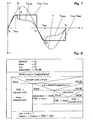
- Circuit breakers are designed for a certain number of mechanical switching operations or operations. Be with them z. B. in case of failure larger currents switched off, As a result, the resulting arc causes the contacts to burn off more than is taken into account during normal switching operations. For the circuit breaker to remain functional, the contacts must be replaced before they are completely burned out. The degree of burning per switching action depends on the energy of the arc occurring. This energy is proportional to the integral ⁇ I 2 dt, where I denotes the current flowing during the arc duration and t denotes the time.
- switches 3 in electrical switchgear 1 are monitored for contact wear by detecting a current flowing through the switch 3 during a switching operation contact current I f at least approximately by a current measurement signal I mess of a current transformer 30 or current sensor 30 as a function of time t, in case of deviations between expected Kotaktstrom I f and current measurement signal I mess a measurement error ⁇ is detected and from the current measurement signal I mess at least one characteristic current value I char determines and is used to determine a contact wear characterizing state variable. Often this estimate is a bit too conservative, but always on the safe side.
- the method can be part of a power system monitoring system.
- Fig. 1 shows an embodiment in which a largely sinusoidal fault current I f is present.
- the current measurement signal I mess saturation occurs and it is at time t max within a quarter period of the fault current signal I f or the voltage applied to the switch 3 mains frequency through a current maximum I.
- the occurrence of the current maximum I max is detected when the deviation or the measurement error ⁇ between the fault current profile I f (t) and the current measurement signal waveform I mess (t) exceeds a tolerance value ⁇ min .
- the contact current I f is typically an overcurrent or short-circuit current I f during a shutdown, the timing of which is known quite accurately in advance.
- a current maximum I max which occurs in the current measurement signal I mess before reaching a quarter period of the mains frequency, a sure indication of a measurement error ⁇ .
- the current maximum I max is now defined as a characteristic current value I char and used to calculate the contact erosion state variable.
- the state variable should preferably be a measure of an arc power during the switching operation and in particular a contact current time integral.
- I mess is the current measurement signal I mess from a first time t 0 at the beginning of the current half-wave in which the switching action occurs until a second time t max , at which a maximum current measurement signal I max occurs detected, and from the second time t max up to a third time t 0 at the end of the current half-wave approximated by the maximum current measurement signal I max .
- the accuracy of the contact erosion calculation depends on how accurately the starting time of the arc can be determined.
- the first time t 0 should be defined as the start time of the arc of the contact current I f .
- the calculation is most accurate when t o is known as a binary indication in the fault record; t o can also be determined with a time delay based on empirical values from an opening command, a protective trigger command or a contact movement of the switch 3. Any fluctuations in this time value are of lesser importance compared to other factors and irregularities in contact erosion. Systematic errors due to too large or too small values of the starting time t 0 can be corrected if z. B. on the occasion of maintenance, the expected burn-up compared with the actual and the time delay is corrected accordingly.
- a time integral ⁇ f (I mess ) dt is then calculated by way of a function f (I mess ) of the section-wise and section-wise approximated Current measuring signal I mess formed.
- the integral ⁇ I mess 2 dt or ⁇ I mess is 1.6 dt with the according to Fig. 1 Approximated current measurement signal I mess determined for approximate determination of Maisabbrands.
- Other functions f (I mess ) are also possible.
- the time integral ⁇ f (I mess ) dt via the function f (I mess ) can be approximated by a summation of function values at interpolation points, wherein the interpolation points z. B. are given by scanning the current measuring signal I mess .
- the state variable is selected equal to the time integral ⁇ f (I mess ) dt times a contact erosion constant c and the contact erosion constant c from manufacturer specifications, in particular from curves over number of permitted switching operations N (I eff ) as a function of an effective turn-off current per switching operation I eff , and / or from empirical values for a switch type and switch application location.
- a sample sample (cnt) of the current measuring signal is read for each cnt value and the condition sample (cnt ) ⁇ I max checked. If the condition is met, an auxiliary variable CWI and equal to sample (cnt) are set.
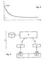
- Fig. 3 shows an example of a curve of a circuit breaker manufacturer, which curve the maximum number of allowed switching operations N with an effective turn-off current per switching operation I eff and thus correlate with a certain cumulative effective cut-off.
- an effective switch-off current I eff can additionally be determined from a curve over the number of permitted switching operations N (I eff ) as a function of the effective switch-off current I eff as a percentage of the performed switching operations relative to the total number of allowed switching actions
- This effective breaking current I eff be determined and the percentages for all relevant executed switching operations are added to a cumulative contact wear.
- the cumulative percentage value represents a control variable for the contact wear state variable Cwsum determined according to the invention.
- Fig. 4 shows a schematic representation of a data acquisition system for the inventive determination of Maisabbrandzustungsiere Cwsum and / or the cumulative percentage of N (I eff ).
- the switchgear 1 has switches 3, typically circuit breakers 3, which are equipped with current transformers 30 or current sensors 30, typically conventional current transformers 30 with saturable core. For example, 1% accuracy and offset converters are saturated with 0.1% -0.5% accuracy at the high currents that cause the most contact wear.
- the current transformers 30 are connected to means 4 for data acquisition at electrical switches 3, in particular with fault recorders 4, protective devices 4 or control devices 4. These data acquisition means 4 are connected via a serial communication 5 or via data carrier 5 with a central detection unit 6 for contact erosion calculation as well preferably connected to a database 7 for contact wear data. With the aid of this device 2 for contact erosion calculation, the method presented above can be implemented. In particular, contact wear can be monitored on-line, ie continuously during operation, or evaluated retroactively from archived data, in particular with a function f (I mess ) of the current measurement signal I mess adapted to a switch type or switch application location .
- the contact wear from records of turn-off currents I mess from disturbance recorder 4 or protection and control devices 4 are determined with Störschreibfunktion, all records of the Abschaltströme I mess a switchgear 1 are collected centrally, especially in an existing or specifically designed for this purpose Störschreiber-collecting system -6, also called SMS or station monitoring system.
- the invention also extends to such a device 2 for contact erosion calculation, which is integrated, for example, in the system control system (not shown) of the switchgear 1, and to an electrical switchgear 1, which comprises such a device 2. Overall, there is an improved conditional controlled instead of periodic maintenance of switches 3 and their switch contacts.
Landscapes
- Keying Circuit Devices (AREA)
- Arc-Extinguishing Devices That Are Switches (AREA)
- Gas-Insulated Switchgears (AREA)
- Remote Monitoring And Control Of Power-Distribution Networks (AREA)
Claims (13)
- Procédé pour déterminer l'usure des contacts dans un commutateur électrique (3), notamment un appareillage de commutation électrique (1) pour haute ou moyenne tension, un courant de contact (If) qui circule à travers le commutateur (3) pendant une opération de commutation étant détecté à l'aide d'un convertisseur de courant (30) et analysé du point de vue de l'usure des contacts, selon lequela) un signal mesuré du courant (Imess) du convertisseur de courant (30) est tout d'abord mesuré en fonction du temps (t) pour déterminer une grandeur d'état (Cwsum) qui caractérise l'usure des contacts,b) s'il se produit des écarts entre le courant de contact (If) attendu et le signal mesuré du courant (Imess), la présence d'une erreur de mesure (Δ) est détectée,
caractérisé en ce quec) en cas de détection de l'erreur de mesure (Δ), au moins un signal mesuré du courant maximum (Imax) est déterminé à partir du signal mesuré du courant (Imess) en tant que valeur caractéristique du courant (Ichar) et utilisé pour déterminer la grandeur d'état (Cwsum). - Procédé selon la revendication 1, caractérisé en ce quea) l'erreur de mesure (Δ) détectée est une saturation du signal mesuré du courant (Imess) etb) la valeur caractéristique du courant (Ichar) utilisée est un signal mesuré du courant maximum (Imax) du convertisseur de courant (30) qui survient avant d'atteindre un quart de période d'un courant alternatif appliqué au commutateur (30).
- Procédé selon l'une des revendications précédentes, caractérisé en ce quea) le courant de contact (If) est une surintensité ou un courant de court-circuit (If) pendant une opération de déconnexion et/oub) la grandeur d'état (Cwsum) est une mesure de la puissance d'un arc électrique pendant l'opération de commutation, notamment une intégrale dans le temps du courant de contact.
- Procédé selon l'une des revendications précédentes, caractérisé en ce quea) le signal mesuré du courant (Imess) est détecté entre un premier instant (t0) au début de la demi période de courant dans laquelle se produit l'opération de commutation et un deuxième instant (tmax) auquel se produit un signal mesuré du courant maximum (Imax) et il est déterminé par approximation par le signal mesuré du courant maximum (Imax) à partir du deuxième instant (tmax) jusqu'à un troisième instant (t0) à la fin de la demi période de courant etb) une intégrale dans le temps ∫f(Imess)dt sur une fonction f (Imess) du signal mesuré du courant (Imess) détecté et déterminé par approximation est calculée pour déterminer la grandeur d'état (Cwsum).
- Procédé selon la revendication 4, caractérisé en ce quea) le premier instant (t0) est défini comme le moment du début d'un arc électrique du courant de contact (If) et il est connu sous la forme d'une indication binaire dans le tracé des perturbations ou alors il est déterminé avec un retard dans le temps basé sur des valeurs empiriques à partir d'une commande d'ouverture, une commande de déclenchement de la protection ou un mouvement des contacts du commutateur (3) etb) notamment que le retard dans le temps est corrigé par comparaison des valeurs réelles avec les valeurs attendues de l'usure des contacts.
- Procédé selon l'une des revendications 4 et 5, caractérisé en ce qu'une fonction de puissance f(Imess) = Imess a, avec a = 1,2 ... 2,2, notamment a = 1,6 ..., 2,0, ou une fonction de racine carrée f (Imess) = (Imess 2)1/2 définissant un courant de déconnexion efficace (Ieff) est utilisée comme fonction f(Imess) du signal mesuré du courant (Imess).
- Procédé selon l'une des revendications 4 à 6, caractérisé en ce quea) la grandeur d'état (Cwsum) est choisie égale à l'intégrale dans le temps ∫f(Imess)dt multipliée par une constante de combustion du contact c etb) la constante de combustion du contact c est déterminée à partir des indications du fabricant, notamment à partir des courbes du nombre d'opérations de commutation autorisées en fonction d'un courant de déconnexion efficace par opération de commutation (Ieff) et/ou à partir des valeurs empiriques pour un type de commutateur et un lieu d'utilisation du commutateur.
- Procédé selon l'une des revendications précédentes, caractérisé en ce quea) un courant de déconnexion efficace (Ieff) est déterminé pour chaque opération de commutation,b) une usure des contacts est déterminée à partir d'une courbe (N(Ieff)) du nombre d'opérations de commutation autorisées (N) en fonction du courant de déconnexion efficace (Ieff) sous la forme d'un pourcentage d'opérations de commutation accomplies par rapport au nombre total autorisé avec ce courant de déconnexion efficace (Ieff) etc) les pourcentages de toutes les opérations de commutation accomplies pertinentes sont additionnés pour former une usure cumulée des contacts.
- Procédé selon l'une des revendications précédentes, caractérisé en ce quea) l'usure des contacts est surveillée en ligne ou interprétée de manière rétroactive à partir de données archivées, notamment avec une fonction f(Imess) adaptée du signal mesuré du courant (Imess) et/oub) l'usure des contacts est déterminée à partir d'enregistrements des courants de déconnexion (Imess) provenant de traceurs de perturbations (4) ou d'appareils de protection et de commande (4) disposant d'une fonction de traçage des perturbations, tous les enregistrements des courants de déconnexion (Imess) d'un appareillage de commutation (1) étant collectés dans un dispositif d'acquisition de données central (6), notamment par le biais d'un support de données (5) ou par communication (5) ou dans un système commun de tracé des perturbations (4-6).
- Produit programme informatique comprenant un programme informatique pour déterminer l'usure des contacts dans un commutateur électrique (3), notamment un appareillage de commutation électrique (1) pour haute ou moyenne tension, lequel peut être chargé et exécuté sur une unité de traitement de données (6), notamment dans un système pilote d'équipement de l'appareillage de commutation (1), caractérisé en ce que le programme informatique, lors de son exécution, exécute les étapes du procédé selon l'une des revendications 1 à 9.
- Dispositif (2) pour mettre en oeuvre le procédé selon l'une des revendications 1 à 9.
- Dispositif (2) selon la revendication 11, caractérisé en ce quea) le commutateur électrique (3) est un commutateur de puissance (3) et/oub) le convertisseur de courant (30) est un convertisseur de courant (30) conventionnel à noyau saturable.
- Appareillage de commutation électrique (1), notamment appareillage de commutation électrique (1) pour haute ou moyenne tension, caractérisé par un dispositif (2) selon l'une des revendications 11 et 12.
Priority Applications (5)
| Application Number | Priority Date | Filing Date | Title |
|---|---|---|---|
| AT03405322T ATE456853T1 (de) | 2003-05-07 | 2003-05-07 | Verfahren und vorrichtung zur ueberwachung von schaltgeräten in elektrischen schaltanlagen |
| EP03405322A EP1475813B1 (fr) | 2003-05-07 | 2003-05-07 | Procédé et dispositif de contrôle d'appareils de commutation dans des installations de commutation électriques |
| DE50312381T DE50312381D1 (de) | 2003-05-07 | 2003-05-07 | Verfahren und Vorrichtung zur Ueberwachung von Schaltgeräten in elektrischen Schaltanlagen |
| ES03405322T ES2338543T3 (es) | 2003-05-07 | 2003-05-07 | Procedimiento y dispositivo de supervision de conmutadores en instalaciones de conmutacion electrica. |
| US10/837,576 US7123461B2 (en) | 2003-05-07 | 2004-05-04 | Method and device for monitoring switchgear in electrical switchgear assemblies |
Applications Claiming Priority (1)
| Application Number | Priority Date | Filing Date | Title |
|---|---|---|---|
| EP03405322A EP1475813B1 (fr) | 2003-05-07 | 2003-05-07 | Procédé et dispositif de contrôle d'appareils de commutation dans des installations de commutation électriques |
Publications (2)
| Publication Number | Publication Date |
|---|---|
| EP1475813A1 EP1475813A1 (fr) | 2004-11-10 |
| EP1475813B1 true EP1475813B1 (fr) | 2010-01-27 |
Family
ID=32982022
Family Applications (1)
| Application Number | Title | Priority Date | Filing Date |
|---|---|---|---|
| EP03405322A Expired - Lifetime EP1475813B1 (fr) | 2003-05-07 | 2003-05-07 | Procédé et dispositif de contrôle d'appareils de commutation dans des installations de commutation électriques |
Country Status (5)
| Country | Link |
|---|---|
| US (1) | US7123461B2 (fr) |
| EP (1) | EP1475813B1 (fr) |
| AT (1) | ATE456853T1 (fr) |
| DE (1) | DE50312381D1 (fr) |
| ES (1) | ES2338543T3 (fr) |
Families Citing this family (22)
| Publication number | Priority date | Publication date | Assignee | Title |
|---|---|---|---|---|
| US7596459B2 (en) * | 2001-02-28 | 2009-09-29 | Quadlogic Controls Corporation | Apparatus and methods for multi-channel electric metering |
| DE102004020045A1 (de) * | 2004-04-21 | 2005-11-10 | Siemens Ag | Verfahren zum Ermitteln eines eine Abnutzung von Schaltkontakten eines Leistungsschalters angebenden Restschaltspiel-Wertes |
| DE102004062266A1 (de) * | 2004-12-23 | 2006-07-13 | Siemens Ag | Verfahren und Vorrichtung zum sicheren Betrieb eines Schaltgerätes |
| EP2372741B1 (fr) * | 2005-11-28 | 2014-01-29 | S & C Electric Company | Procédé pour définir la fin de vie d'un interrupteur sous vide |
| EP1793235A1 (fr) * | 2005-11-30 | 2007-06-06 | ABB Technology AG | Système de surveillance pour des commutateurs à haute tension |
| US8560255B2 (en) * | 2008-12-12 | 2013-10-15 | Schneider Electric USA, Inc. | Power metering and merging unit capabilities in a single IED |
| FR2945661A1 (fr) * | 2009-05-18 | 2010-11-19 | Schneider Electric Ind Sas | Evaluation de l'usure de contacts enfonces par la variation de la rotation de l'arbre des poles |
| US20110062960A1 (en) * | 2009-09-15 | 2011-03-17 | Lenin Prakash | Device and method to monitor electrical contact status |
| ES2380182T3 (es) * | 2009-11-25 | 2012-05-09 | Abb Research Ltd. | Procedimiento y dispositivo para la determinación de un desgaste de un elemento de contacto |
| US20110133743A1 (en) * | 2010-04-30 | 2011-06-09 | Werner Barton | Fault detection device and method for detecting an electrical fault |
| WO2012072810A1 (fr) | 2010-12-02 | 2012-06-07 | Abb Research Ltd | Procédé et dispositif de contrôle d'appareils de connexion |
| DE102011080826B4 (de) * | 2011-08-11 | 2016-01-21 | Siemens Aktiengesellschaft | Verfahren zum Ermitteln der Lichtbogenleistung eines Schalters, Verfahren zum Auslösen eines Schalters anhand der Lichtbogenleistung und Verfahren zur Ermittlung der Belastung der Kontakte eines Schalters anhand der Lichtbogenenergie |
| DE102013219243B4 (de) * | 2013-09-25 | 2018-01-18 | Robert Bosch Gmbh | Verfahren und Einrichtung zur Bestimmung der Alterung eines elektronischen Unterbrechungselements, insbesondere eines Leistungsschützes |
| FR3060758B1 (fr) | 2016-12-16 | 2021-01-08 | Schneider Electric Ind Sas | Procede et dispositif de diagnostic d'usure d'un appareil electrique de coupure, et appareil electrique comportant un tel dispositif |
| FR3082005B1 (fr) * | 2018-06-01 | 2020-11-27 | Schneider Electric Ind Sas | Procede et dispositif de diagnostic d'usure d'un appareil electrique de coupure, et appareil electrique comportant un tel dispositif |
| ES2878274T3 (es) * | 2018-08-03 | 2021-11-18 | Rittal Gmbh & Co Kg | Dispositivo y procedimiento para la comprobación de un contenido de armario de distribución después de un montaje basado en la planificación |
| CN111505496B (zh) * | 2020-05-08 | 2021-02-02 | 西安交通大学 | 一种基于电弧能量的真空断路器电寿命评估方法 |
| FR3112651B1 (fr) * | 2020-07-20 | 2023-05-12 | Schneider Electric Ind Sas | Procédés pour estimer une propriété d’un appareil de commutation électrique, dispositifs pour mettre en œuvre ces procédés |
| DE102020209645A1 (de) * | 2020-07-30 | 2022-02-03 | Siemens Aktiengesellschaft | Verfahren zur Zustandsbestimmung einer elektrischen Schaltanlage, Überwachungseinheit für eine elektrische Schaltanlage und elektrische Schaltanlage |
| US12087528B2 (en) * | 2021-02-01 | 2024-09-10 | Ge Infrastructure Technology Llc | Enhanced switchgear monitoring and diagnostics in a protection relay |
| CN113552436A (zh) * | 2021-07-27 | 2021-10-26 | 中船九江精达科技股份有限公司 | 一种中小型精密机械系统装配质量检测方法 |
| CN114076868B (zh) * | 2021-11-18 | 2022-08-02 | 广东电网有限责任公司广州供电局 | 一种开关缺陷识别方法、装置、设备和可读存储介质 |
Family Cites Families (5)
| Publication number | Priority date | Publication date | Assignee | Title |
|---|---|---|---|---|
| SE439692B (sv) * | 1983-10-24 | 1985-06-24 | Asea Ab | Anordning for overvakning av konditionen hos en elektrisk apparat med strombrytande kontakter, i synnerhet en hogspenningsbrytare |
| DE3505818A1 (de) | 1985-02-20 | 1986-08-21 | Licentia Patent-Verwaltungs-Gmbh, 6000 Frankfurt | Ueberwachungs- und kontrolleinrichtung fuer schaltgeraete |
| FR2602610B1 (fr) * | 1986-08-08 | 1994-05-20 | Merlin Et Gerin | Declencheur statique d'un disjoncteur electrique a indicateur d'usure des contacts |
| US6466023B2 (en) * | 1998-12-28 | 2002-10-15 | General Electric Company | Method of determining contact wear in a trip unit |
| DE19928192B4 (de) | 1999-06-19 | 2005-08-25 | Abb Patent Gmbh | Verfahren zur Rekonstruktion eines Stromes |
-
2003
- 2003-05-07 DE DE50312381T patent/DE50312381D1/de not_active Expired - Lifetime
- 2003-05-07 AT AT03405322T patent/ATE456853T1/de not_active IP Right Cessation
- 2003-05-07 EP EP03405322A patent/EP1475813B1/fr not_active Expired - Lifetime
- 2003-05-07 ES ES03405322T patent/ES2338543T3/es not_active Expired - Lifetime
-
2004
- 2004-05-04 US US10/837,576 patent/US7123461B2/en not_active Expired - Lifetime
Also Published As
| Publication number | Publication date |
|---|---|
| US20040223276A1 (en) | 2004-11-11 |
| US7123461B2 (en) | 2006-10-17 |
| ES2338543T3 (es) | 2010-05-10 |
| EP1475813A1 (fr) | 2004-11-10 |
| DE50312381D1 (de) | 2010-03-18 |
| ATE456853T1 (de) | 2010-02-15 |
Similar Documents
| Publication | Publication Date | Title |
|---|---|---|
| EP1475813B1 (fr) | Procédé et dispositif de contrôle d'appareils de commutation dans des installations de commutation électriques | |
| DE69414328T2 (de) | Lichtbogenerfassung über die Stromänderung | |
| EP2017867B1 (fr) | Dispositif de mesure destiné à la mesure d'un signal analogique périodique | |
| DE69601218T3 (de) | Elektrische differentialschutzvorrichtung mit prüfkreis | |
| EP1002325B1 (fr) | PROCEDE POUR DETERMINER DES DONNEES SPECIFIQUES D'APPAREILS DE COMMUTATION AU NIVEAU DE CONTACTS INSTALLES DANS LESDITS APPAREILS DE COMMUTATION ET/OU DONNEES SPECIFIQUES DE FONCTIONNEMENT DANS UN RESEAU COMMUTE DE FAçON CORRESPONDANTE | |
| DE3750820T2 (de) | Abstandsschutz von Dreiphasenverteiltransformatoren. | |
| EP0694937B1 (fr) | Procédé et dispositif pour déterminer la vie résiduelle de contacts dans les appareils de commutation | |
| EP0193732A1 (fr) | Dispositif pour surveiller et contrôler des commutateurs et des combinaisons de commutateurs | |
| DE102015108538A1 (de) | Detektionsverfahren und Detektionseinrichtung für Fehlerlichtbögen | |
| DE112012001189T5 (de) | Verfahren, Systeme und Einrichtungen zum Erkennen paralleler elektrischer Fehlerlichtbögen | |
| DE102014200946B4 (de) | Überlast-Überwachungsvorrichtung und Verfahren zur Überlast-Überwachung | |
| EP4377984B1 (fr) | Procédé et dispositif disjoncteur | |
| DE102008012605A1 (de) | Schutzschaltgerät zum Überwachen des elektrischen Stromflusses zu einem elektrischen Verbrauch bzw. Verfahren zur Überwachung des elektrischen Stromflusses zu einem elektrischen Verbraucher durch ein Schutzschaltgerät | |
| DE2406197C3 (de) | Verfahren und Einrichtung zur Detektion von Kurzschlüssen | |
| DE2727378A1 (de) | Einrichtung zur kontrolle der betriebsfaehigkeit von schaltgeraeten | |
| DE102012215166B4 (de) | Schaltgerät für einen Einphasenmotor und einen Drehstrommotor | |
| WO2012072810A1 (fr) | Procédé et dispositif de contrôle d'appareils de connexion | |
| DE19901119B4 (de) | Überwachungssystem für eine gasisolierte Hochspannungsschaltanlage | |
| EP4367704B1 (fr) | Appareil de connexion de protection | |
| EP0696830A1 (fr) | Localiseur des pertes à la terre dans des réseaux électriques avec une bobine de mise à la terre | |
| DE102022201960A1 (de) | Verfahren und Schutzschalter zur Bestimmung von sich auf eine Last beziehenden Informationen | |
| DE102007006564A1 (de) | Leitungsschutzschalter oder Leistungsschalter | |
| DE4111831A1 (de) | Verfahren zur ausloesung eines elektrischen schalters sowie vorrichtung zur durchfuehrung des verfahrens | |
| DE10117372B4 (de) | Schutzeinrichtung, Schutzanordnung und Schutzverfahren für eine elektrische Leitung | |
| DE102020216428A1 (de) | Schutzschaltgerät und Verfahren |
Legal Events
| Date | Code | Title | Description |
|---|---|---|---|
| PUAI | Public reference made under article 153(3) epc to a published international application that has entered the european phase |
Free format text: ORIGINAL CODE: 0009012 |
|
| AK | Designated contracting states |
Kind code of ref document: A1 Designated state(s): AT BE BG CH CY CZ DE DK EE ES FI FR GB GR HU IE IT LI LU MC NL PT RO SE SI SK TR |
|
| AX | Request for extension of the european patent |
Extension state: AL LT LV MK |
|
| 17P | Request for examination filed |
Effective date: 20050414 |
|
| AKX | Designation fees paid |
Designated state(s): AT BE BG CH CY CZ DE DK EE ES FI FR GB GR HU IE IT LI LU MC NL PT RO SE SI SK TR |
|
| 17Q | First examination report despatched |
Effective date: 20070420 |
|
| GRAP | Despatch of communication of intention to grant a patent |
Free format text: ORIGINAL CODE: EPIDOSNIGR1 |
|
| GRAS | Grant fee paid |
Free format text: ORIGINAL CODE: EPIDOSNIGR3 |
|
| GRAA | (expected) grant |
Free format text: ORIGINAL CODE: 0009210 |
|
| AK | Designated contracting states |
Kind code of ref document: B1 Designated state(s): AT BE BG CH CY CZ DE DK EE ES FI FR GB GR HU IE IT LI LU MC NL PT RO SE SI SK TR |
|
| REG | Reference to a national code |
Ref country code: GB Ref legal event code: FG4D Free format text: NOT ENGLISH |
|
| REG | Reference to a national code |
Ref country code: CH Ref legal event code: EP |
|
| REG | Reference to a national code |
Ref country code: IE Ref legal event code: FG4D |
|
| REF | Corresponds to: |
Ref document number: 50312381 Country of ref document: DE Date of ref document: 20100318 Kind code of ref document: P |
|
| REG | Reference to a national code |
Ref country code: ES Ref legal event code: FG2A Ref document number: 2338543 Country of ref document: ES Kind code of ref document: T3 |
|
| REG | Reference to a national code |
Ref country code: SE Ref legal event code: TRGR |
|
| REG | Reference to a national code |
Ref country code: NL Ref legal event code: VDEP Effective date: 20100127 |
|
| PG25 | Lapsed in a contracting state [announced via postgrant information from national office to epo] |
Ref country code: PT Free format text: LAPSE BECAUSE OF FAILURE TO SUBMIT A TRANSLATION OF THE DESCRIPTION OR TO PAY THE FEE WITHIN THE PRESCRIBED TIME-LIMIT Effective date: 20100527 Ref country code: NL Free format text: LAPSE BECAUSE OF FAILURE TO SUBMIT A TRANSLATION OF THE DESCRIPTION OR TO PAY THE FEE WITHIN THE PRESCRIBED TIME-LIMIT Effective date: 20100127 |
|
| REG | Reference to a national code |
Ref country code: IE Ref legal event code: FD4D |
|
| PG25 | Lapsed in a contracting state [announced via postgrant information from national office to epo] |
Ref country code: SI Free format text: LAPSE BECAUSE OF FAILURE TO SUBMIT A TRANSLATION OF THE DESCRIPTION OR TO PAY THE FEE WITHIN THE PRESCRIBED TIME-LIMIT Effective date: 20100127 Ref country code: FI Free format text: LAPSE BECAUSE OF FAILURE TO SUBMIT A TRANSLATION OF THE DESCRIPTION OR TO PAY THE FEE WITHIN THE PRESCRIBED TIME-LIMIT Effective date: 20100127 |
|
| PG25 | Lapsed in a contracting state [announced via postgrant information from national office to epo] |
Ref country code: EE Free format text: LAPSE BECAUSE OF FAILURE TO SUBMIT A TRANSLATION OF THE DESCRIPTION OR TO PAY THE FEE WITHIN THE PRESCRIBED TIME-LIMIT Effective date: 20100127 Ref country code: GR Free format text: LAPSE BECAUSE OF FAILURE TO SUBMIT A TRANSLATION OF THE DESCRIPTION OR TO PAY THE FEE WITHIN THE PRESCRIBED TIME-LIMIT Effective date: 20100428 Ref country code: IE Free format text: LAPSE BECAUSE OF FAILURE TO SUBMIT A TRANSLATION OF THE DESCRIPTION OR TO PAY THE FEE WITHIN THE PRESCRIBED TIME-LIMIT Effective date: 20100127 Ref country code: RO Free format text: LAPSE BECAUSE OF FAILURE TO SUBMIT A TRANSLATION OF THE DESCRIPTION OR TO PAY THE FEE WITHIN THE PRESCRIBED TIME-LIMIT Effective date: 20100127 Ref country code: CY Free format text: LAPSE BECAUSE OF FAILURE TO SUBMIT A TRANSLATION OF THE DESCRIPTION OR TO PAY THE FEE WITHIN THE PRESCRIBED TIME-LIMIT Effective date: 20100127 |
|
| BERE | Be: lapsed |
Owner name: ABB TECHNOLOGY A.G. Effective date: 20100531 |
|
| PG25 | Lapsed in a contracting state [announced via postgrant information from national office to epo] |
Ref country code: SK Free format text: LAPSE BECAUSE OF FAILURE TO SUBMIT A TRANSLATION OF THE DESCRIPTION OR TO PAY THE FEE WITHIN THE PRESCRIBED TIME-LIMIT Effective date: 20100127 Ref country code: CZ Free format text: LAPSE BECAUSE OF FAILURE TO SUBMIT A TRANSLATION OF THE DESCRIPTION OR TO PAY THE FEE WITHIN THE PRESCRIBED TIME-LIMIT Effective date: 20100127 Ref country code: BG Free format text: LAPSE BECAUSE OF FAILURE TO SUBMIT A TRANSLATION OF THE DESCRIPTION OR TO PAY THE FEE WITHIN THE PRESCRIBED TIME-LIMIT Effective date: 20100427 |
|
| PLBE | No opposition filed within time limit |
Free format text: ORIGINAL CODE: 0009261 |
|
| STAA | Information on the status of an ep patent application or granted ep patent |
Free format text: STATUS: NO OPPOSITION FILED WITHIN TIME LIMIT |
|
| PG25 | Lapsed in a contracting state [announced via postgrant information from national office to epo] |
Ref country code: MC Free format text: LAPSE BECAUSE OF NON-PAYMENT OF DUE FEES Effective date: 20100531 |
|
| REG | Reference to a national code |
Ref country code: CH Ref legal event code: PL |
|
| 26N | No opposition filed |
Effective date: 20101028 |
|
| PG25 | Lapsed in a contracting state [announced via postgrant information from national office to epo] |
Ref country code: DK Free format text: LAPSE BECAUSE OF FAILURE TO SUBMIT A TRANSLATION OF THE DESCRIPTION OR TO PAY THE FEE WITHIN THE PRESCRIBED TIME-LIMIT Effective date: 20100127 |
|
| PG25 | Lapsed in a contracting state [announced via postgrant information from national office to epo] |
Ref country code: CH Free format text: LAPSE BECAUSE OF NON-PAYMENT OF DUE FEES Effective date: 20100531 Ref country code: LI Free format text: LAPSE BECAUSE OF NON-PAYMENT OF DUE FEES Effective date: 20100531 |
|
| PG25 | Lapsed in a contracting state [announced via postgrant information from national office to epo] |
Ref country code: IT Free format text: LAPSE BECAUSE OF FAILURE TO SUBMIT A TRANSLATION OF THE DESCRIPTION OR TO PAY THE FEE WITHIN THE PRESCRIBED TIME-LIMIT Effective date: 20100127 Ref country code: BE Free format text: LAPSE BECAUSE OF NON-PAYMENT OF DUE FEES Effective date: 20100531 |
|
| PG25 | Lapsed in a contracting state [announced via postgrant information from national office to epo] |
Ref country code: AT Free format text: LAPSE BECAUSE OF NON-PAYMENT OF DUE FEES Effective date: 20100507 |
|
| PG25 | Lapsed in a contracting state [announced via postgrant information from national office to epo] |
Ref country code: HU Free format text: LAPSE BECAUSE OF FAILURE TO SUBMIT A TRANSLATION OF THE DESCRIPTION OR TO PAY THE FEE WITHIN THE PRESCRIBED TIME-LIMIT Effective date: 20100728 Ref country code: LU Free format text: LAPSE BECAUSE OF NON-PAYMENT OF DUE FEES Effective date: 20100507 |
|
| PG25 | Lapsed in a contracting state [announced via postgrant information from national office to epo] |
Ref country code: TR Free format text: LAPSE BECAUSE OF FAILURE TO SUBMIT A TRANSLATION OF THE DESCRIPTION OR TO PAY THE FEE WITHIN THE PRESCRIBED TIME-LIMIT Effective date: 20100127 |
|
| REG | Reference to a national code |
Ref country code: FR Ref legal event code: PLFP Year of fee payment: 14 |
|
| PGFP | Annual fee paid to national office [announced via postgrant information from national office to epo] |
Ref country code: ES Payment date: 20160512 Year of fee payment: 14 Ref country code: GB Payment date: 20160520 Year of fee payment: 14 |
|
| PGFP | Annual fee paid to national office [announced via postgrant information from national office to epo] |
Ref country code: SE Payment date: 20160519 Year of fee payment: 14 |
|
| REG | Reference to a national code |
Ref country code: DE Ref legal event code: R081 Ref document number: 50312381 Country of ref document: DE Owner name: HITACHI ENERGY SWITZERLAND AG, CH Free format text: FORMER OWNER: ABB TECHNOLOGY AG, ZUERICH, CH Ref country code: DE Ref legal event code: R081 Ref document number: 50312381 Country of ref document: DE Owner name: ABB SCHWEIZ AG, CH Free format text: FORMER OWNER: ABB TECHNOLOGY AG, ZUERICH, CH Ref country code: DE Ref legal event code: R081 Ref document number: 50312381 Country of ref document: DE Owner name: ABB POWER GRIDS SWITZERLAND AG, CH Free format text: FORMER OWNER: ABB TECHNOLOGY AG, ZUERICH, CH Ref country code: DE Ref legal event code: R082 Ref document number: 50312381 Country of ref document: DE Representative=s name: DENNEMEYER & ASSOCIATES S.A., DE Ref country code: DE Ref legal event code: R082 Ref document number: 50312381 Country of ref document: DE Representative=s name: ZIMMERMANN & PARTNER PATENTANWAELTE MBB, DE |
|
| REG | Reference to a national code |
Ref country code: FR Ref legal event code: PLFP Year of fee payment: 15 |
|
| REG | Reference to a national code |
Ref country code: SE Ref legal event code: EUG |
|
| GBPC | Gb: european patent ceased through non-payment of renewal fee |
Effective date: 20170507 |
|
| PG25 | Lapsed in a contracting state [announced via postgrant information from national office to epo] |
Ref country code: SE Free format text: LAPSE BECAUSE OF NON-PAYMENT OF DUE FEES Effective date: 20170508 |
|
| PG25 | Lapsed in a contracting state [announced via postgrant information from national office to epo] |
Ref country code: GB Free format text: LAPSE BECAUSE OF NON-PAYMENT OF DUE FEES Effective date: 20170507 |
|
| REG | Reference to a national code |
Ref country code: FR Ref legal event code: PLFP Year of fee payment: 16 |
|
| REG | Reference to a national code |
Ref country code: ES Ref legal event code: FD2A Effective date: 20180703 |
|
| PG25 | Lapsed in a contracting state [announced via postgrant information from national office to epo] |
Ref country code: ES Free format text: LAPSE BECAUSE OF NON-PAYMENT OF DUE FEES Effective date: 20170508 |
|
| REG | Reference to a national code |
Ref country code: FR Ref legal event code: TP Owner name: ABB SCHWEIZ AG, CH Effective date: 20180912 |
|
| REG | Reference to a national code |
Ref country code: DE Ref legal event code: R081 Ref document number: 50312381 Country of ref document: DE Owner name: HITACHI ENERGY SWITZERLAND AG, CH Free format text: FORMER OWNER: ABB SCHWEIZ AG, BADEN, CH Ref country code: DE Ref legal event code: R082 Ref document number: 50312381 Country of ref document: DE Representative=s name: DENNEMEYER & ASSOCIATES S.A., DE Ref country code: DE Ref legal event code: R081 Ref document number: 50312381 Country of ref document: DE Owner name: ABB POWER GRIDS SWITZERLAND AG, CH Free format text: FORMER OWNER: ABB SCHWEIZ AG, BADEN, CH |
|
| REG | Reference to a national code |
Ref country code: DE Ref legal event code: R081 Ref document number: 50312381 Country of ref document: DE Owner name: HITACHI ENERGY SWITZERLAND AG, CH Free format text: FORMER OWNER: ABB POWER GRIDS SWITZERLAND AG, BADEN, CH |
|
| PGFP | Annual fee paid to national office [announced via postgrant information from national office to epo] |
Ref country code: FR Payment date: 20220523 Year of fee payment: 20 Ref country code: DE Payment date: 20220519 Year of fee payment: 20 |
|
| REG | Reference to a national code |
Ref country code: DE Ref legal event code: R071 Ref document number: 50312381 Country of ref document: DE |