EP1475784A1 - Rewritable optical recording medium and optical recording method - Google Patents
Rewritable optical recording medium and optical recording method Download PDFInfo
- Publication number
- EP1475784A1 EP1475784A1 EP03705130A EP03705130A EP1475784A1 EP 1475784 A1 EP1475784 A1 EP 1475784A1 EP 03705130 A EP03705130 A EP 03705130A EP 03705130 A EP03705130 A EP 03705130A EP 1475784 A1 EP1475784 A1 EP 1475784A1
- Authority
- EP
- European Patent Office
- Prior art keywords
- recording
- velocity
- integer
- mark
- record
- Prior art date
- Legal status (The legal status is an assumption and is not a legal conclusion. Google has not performed a legal analysis and makes no representation as to the accuracy of the status listed.)
- Granted
Links
Images






















Classifications
-
- G—PHYSICS
- G11—INFORMATION STORAGE
- G11B—INFORMATION STORAGE BASED ON RELATIVE MOVEMENT BETWEEN RECORD CARRIER AND TRANSDUCER
- G11B7/00—Recording or reproducing by optical means, e.g. recording using a thermal beam of optical radiation by modifying optical properties or the physical structure, reproducing using an optical beam at lower power by sensing optical properties; Record carriers therefor
- G11B7/24—Record carriers characterised by shape, structure or physical properties, or by the selection of the material
- G11B7/241—Record carriers characterised by shape, structure or physical properties, or by the selection of the material characterised by the selection of the material
- G11B7/242—Record carriers characterised by shape, structure or physical properties, or by the selection of the material characterised by the selection of the material of recording layers
- G11B7/243—Record carriers characterised by shape, structure or physical properties, or by the selection of the material characterised by the selection of the material of recording layers comprising inorganic materials only, e.g. ablative layers
-
- G—PHYSICS
- G11—INFORMATION STORAGE
- G11B—INFORMATION STORAGE BASED ON RELATIVE MOVEMENT BETWEEN RECORD CARRIER AND TRANSDUCER
- G11B7/00—Recording or reproducing by optical means, e.g. recording using a thermal beam of optical radiation by modifying optical properties or the physical structure, reproducing using an optical beam at lower power by sensing optical properties; Record carriers therefor
- G11B7/004—Recording, reproducing or erasing methods; Read, write or erase circuits therefor
- G11B7/0045—Recording
- G11B7/00454—Recording involving phase-change effects
-
- G—PHYSICS
- G11—INFORMATION STORAGE
- G11B—INFORMATION STORAGE BASED ON RELATIVE MOVEMENT BETWEEN RECORD CARRIER AND TRANSDUCER
- G11B7/00—Recording or reproducing by optical means, e.g. recording using a thermal beam of optical radiation by modifying optical properties or the physical structure, reproducing using an optical beam at lower power by sensing optical properties; Record carriers therefor
- G11B7/004—Recording, reproducing or erasing methods; Read, write or erase circuits therefor
- G11B7/006—Overwriting
- G11B7/0062—Overwriting strategies, e.g. recording pulse sequences with erasing level used for phase-change media
-
- G—PHYSICS
- G11—INFORMATION STORAGE
- G11B—INFORMATION STORAGE BASED ON RELATIVE MOVEMENT BETWEEN RECORD CARRIER AND TRANSDUCER
- G11B7/00—Recording or reproducing by optical means, e.g. recording using a thermal beam of optical radiation by modifying optical properties or the physical structure, reproducing using an optical beam at lower power by sensing optical properties; Record carriers therefor
- G11B7/12—Heads, e.g. forming of the optical beam spot or modulation of the optical beam
- G11B7/125—Optical beam sources therefor, e.g. laser control circuitry specially adapted for optical storage devices; Modulators, e.g. means for controlling the size or intensity of optical spots or optical traces
- G11B7/126—Circuits, methods or arrangements for laser control or stabilisation
-
- G—PHYSICS
- G11—INFORMATION STORAGE
- G11B—INFORMATION STORAGE BASED ON RELATIVE MOVEMENT BETWEEN RECORD CARRIER AND TRANSDUCER
- G11B7/00—Recording or reproducing by optical means, e.g. recording using a thermal beam of optical radiation by modifying optical properties or the physical structure, reproducing using an optical beam at lower power by sensing optical properties; Record carriers therefor
- G11B7/24—Record carriers characterised by shape, structure or physical properties, or by the selection of the material
- G11B7/241—Record carriers characterised by shape, structure or physical properties, or by the selection of the material characterised by the selection of the material
- G11B7/242—Record carriers characterised by shape, structure or physical properties, or by the selection of the material characterised by the selection of the material of recording layers
- G11B7/243—Record carriers characterised by shape, structure or physical properties, or by the selection of the material characterised by the selection of the material of recording layers comprising inorganic materials only, e.g. ablative layers
- G11B2007/24302—Metals or metalloids
- G11B2007/24312—Metals or metalloids group 14 elements (e.g. Si, Ge, Sn)
-
- G—PHYSICS
- G11—INFORMATION STORAGE
- G11B—INFORMATION STORAGE BASED ON RELATIVE MOVEMENT BETWEEN RECORD CARRIER AND TRANSDUCER
- G11B7/00—Recording or reproducing by optical means, e.g. recording using a thermal beam of optical radiation by modifying optical properties or the physical structure, reproducing using an optical beam at lower power by sensing optical properties; Record carriers therefor
- G11B7/24—Record carriers characterised by shape, structure or physical properties, or by the selection of the material
- G11B7/241—Record carriers characterised by shape, structure or physical properties, or by the selection of the material characterised by the selection of the material
- G11B7/242—Record carriers characterised by shape, structure or physical properties, or by the selection of the material characterised by the selection of the material of recording layers
- G11B7/243—Record carriers characterised by shape, structure or physical properties, or by the selection of the material characterised by the selection of the material of recording layers comprising inorganic materials only, e.g. ablative layers
- G11B2007/24302—Metals or metalloids
- G11B2007/24314—Metals or metalloids group 15 elements (e.g. Sb, Bi)
-
- G—PHYSICS
- G11—INFORMATION STORAGE
- G11B—INFORMATION STORAGE BASED ON RELATIVE MOVEMENT BETWEEN RECORD CARRIER AND TRANSDUCER
- G11B7/00—Recording or reproducing by optical means, e.g. recording using a thermal beam of optical radiation by modifying optical properties or the physical structure, reproducing using an optical beam at lower power by sensing optical properties; Record carriers therefor
- G11B7/24—Record carriers characterised by shape, structure or physical properties, or by the selection of the material
- G11B7/241—Record carriers characterised by shape, structure or physical properties, or by the selection of the material characterised by the selection of the material
- G11B7/242—Record carriers characterised by shape, structure or physical properties, or by the selection of the material characterised by the selection of the material of recording layers
- G11B7/243—Record carriers characterised by shape, structure or physical properties, or by the selection of the material characterised by the selection of the material of recording layers comprising inorganic materials only, e.g. ablative layers
- G11B2007/24302—Metals or metalloids
- G11B2007/24316—Metals or metalloids group 16 elements (i.e. chalcogenides, Se, Te)
-
- G—PHYSICS
- G11—INFORMATION STORAGE
- G11B—INFORMATION STORAGE BASED ON RELATIVE MOVEMENT BETWEEN RECORD CARRIER AND TRANSDUCER
- G11B7/00—Recording or reproducing by optical means, e.g. recording using a thermal beam of optical radiation by modifying optical properties or the physical structure, reproducing using an optical beam at lower power by sensing optical properties; Record carriers therefor
- G11B7/24—Record carriers characterised by shape, structure or physical properties, or by the selection of the material
- G11B7/241—Record carriers characterised by shape, structure or physical properties, or by the selection of the material characterised by the selection of the material
- G11B7/252—Record carriers characterised by shape, structure or physical properties, or by the selection of the material characterised by the selection of the material of layers other than recording layers
- G11B7/258—Record carriers characterised by shape, structure or physical properties, or by the selection of the material characterised by the selection of the material of layers other than recording layers of reflective layers
- G11B7/259—Record carriers characterised by shape, structure or physical properties, or by the selection of the material characterised by the selection of the material of layers other than recording layers of reflective layers based on silver
-
- G—PHYSICS
- G11—INFORMATION STORAGE
- G11B—INFORMATION STORAGE BASED ON RELATIVE MOVEMENT BETWEEN RECORD CARRIER AND TRANSDUCER
- G11B7/00—Recording or reproducing by optical means, e.g. recording using a thermal beam of optical radiation by modifying optical properties or the physical structure, reproducing using an optical beam at lower power by sensing optical properties; Record carriers therefor
- G11B7/24—Record carriers characterised by shape, structure or physical properties, or by the selection of the material
- G11B7/26—Apparatus or processes specially adapted for the manufacture of record carriers
-
- Y—GENERAL TAGGING OF NEW TECHNOLOGICAL DEVELOPMENTS; GENERAL TAGGING OF CROSS-SECTIONAL TECHNOLOGIES SPANNING OVER SEVERAL SECTIONS OF THE IPC; TECHNICAL SUBJECTS COVERED BY FORMER USPC CROSS-REFERENCE ART COLLECTIONS [XRACs] AND DIGESTS
- Y10—TECHNICAL SUBJECTS COVERED BY FORMER USPC
- Y10T—TECHNICAL SUBJECTS COVERED BY FORMER US CLASSIFICATION
- Y10T428/00—Stock material or miscellaneous articles
- Y10T428/21—Circular sheet or circular blank
Definitions
- the present invention relates to a rewritable optical recording medium (in the present invention, a rewritable optical recording medium may simply be referred to as an optical recording medium, a medium, an optical disk or a disk) which has retrieving interchangeability with a readout-only medium specified in conventional CD-ROM or DVD (-ROM) standards, and a recording method therefor.
- a rewritable optical recording medium capable of one-beam overwriting at a linear velocity as high as at least 20 m/s.
- it provides a recording method, whereby excellent recording can be carried out within a wide range of recording linear velocity.
- CD compact disk
- DVD digital versatile disk
- phase-change type rewritable compact disks CD-RW, CD-Rewritable
- phase-change type rewritable DVD (tradename: DVD-RW, DVD+RW, in this specification, rewritable DVD may sometimes be referred to as RW-DVD) have been used as optical recording media interchangeable with CD or DVD.
- phase-change type CD-RW or RW-DVD utilizes a phase difference and a difference in reflectivity caused by a difference in the refractive index between an amorphous state and a crystalline state to detect recording information signals.
- a usual phase-change type CD-RW or RW-DVD has a structure comprising a substrate, and a lower protective layer, a phase-change type recording layer, an upper protective layer and a reflective layer, formed on the substrate, so that multiple interference of these layers can be utilized to control the difference in reflectivity and the phase difference and to provide interchangeability with CD or DVD.
- recording on CD-RW or RW-DVD means recording by overwriting wherein recording and erasing are carried out simultaneously.
- the reference velocity (hereinafter referred to also as 1-time velocity) in recording/retrieving of CD is a linear velocity (in this specification, "a linear velocity” may simply be referred to as "linear speed" of from 1.2 to 1.4 m/s.
- a linear velocity may simply be referred to as "linear speed” of from 1.2 to 1.4 m/s.
- a high velocity retrieving at a level of 40-times velocity at the maximum has been already realized, and a low velocity at a level of 1-time velocity is used only for retrieving of musics or images.
- CLV constant linear velocity mode
- CAV constant angular velocity mode
- CD-R has already accomplished 24-times velocity for recording, and also for CD-RW, it is desired to increase the transfer rate in recording.
- the reference velocity (hereinafter referred to also as 1-time velocity) in retrieving of DVD is a linear velocity of 3.49 m/s, but with DVD-ROM, high velocity retrieving at a level of 16-times velocity at the maximum has already been realized, and a low velocity at a level of 1-time velocity is used only for retrieving of musics or images.
- phase-change medium and a recording method have been desired whereby recording can be carried out at a higher velocity.
- a rewritable phase-change medium capable of recording up to a high linear velocity of at least 20-times velocity for CD or at least 6-times velocity for RW-DVD, has not yet been realized.
- a rewritable CD or DVD medium which is overwritable at a high linear velocity at a level of exceeding a linear velocity of 20 m/s, has not yet been realized.
- a first reason for why such a rewritable phase-change medium can not be realized, is that it is difficult to simultaneously satisfy the archival stability of amorphous marks and erasing in a short time by high speed crystallization of amorphous marks.
- a recording material comprising a SbTe alloy as the main component which is used as a material for a recording layer of CD-RW overwritable at 1 to 4-times velocity or RW-DVD overwritable at up to about 2.4-times velocity
- high speed crystallization is possible by relatively increasing the Sb content, whereby overwriting at a linear speed of at least 20 m/s will be possible.
- CD-RW or RW-DVD has a restriction such that it is necessary to secure retrieving interchangeability with a widely used CD-ROM drive or DVD-ROM drive for retrieving only.
- CD-RW in order to secure retrieving interchangeability, it is necessary to satisfy not only a high modulation at a level of a modulation of from 55 to 70% but also a reflectivity of from 15 to 25% and other servo signal characteristics.
- RW-DVD in order to secure retrieving interchangeability, it is necessary to satisfy not only a high modulation at a level of a modulation of from 55 to 70% but also a reflectivity of from 18 to 30% and other servo signal characteristics.
- CD-RW or RW-DVD overwritable at a high linear velocity of at least 24 m/s has not yet been realized, is that a fairly strict recording pulse strategy (pulse division method) is specified in CD-RW standards or RW-DVD standards.
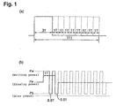
- a recording pulse strategy as shown in Fig. 1 is specified. Accordingly, in a currently practically used recording device, IC for generating such a recording pulse strategy is employed. Accordingly, with a currently practically used recording device, it is obliged to carry out recording in a wide range of linear velocity ranging from 1-time velocity to 8- to 10-times velocity by such a recording pulse strategy or by a recording pulse strategy having certain changes made thereto.
- a similar recording strategy is specified.
- a characteristic of such a recording strategy is that an amorphous mark having a nT mark length is divided into n-1 recording pulses and cooling pulses (off-pulses) for recording. Therefore, in such a recording strategy, an average repeating period for a pair of a recording pulse and a cooling pulse is made to be about 1T.
- Fig. 1(a) shows EFM modulated data signals having time lengths of from 3T to 11T
- Fig. 1(b) shows the practical recording laser powers generated on the basis of such data signals.
- Pw represents a writing power to form an amorphous mark by melting and quenching the recording layer
- Pe represents an erasing power to erase an amorphous mark by crystallization
- a bias power Pb is substantially the same as a retrieving power Pr of a retrieving laser beam.
- Writing power (Pw) irradiation sections are referred to as recording pulses, and bias power irradiation sections are referred to as off-pulses.
- data signals having time lengths of 14T are added to the above-mentioned data signals having time lengths of from 3 to 11T.
- a repeating period for a recording pulse and an off-pulse is basically constant as a reference clock period T.
- the reference clock period T is made to have a high frequency in proportion to the linear velocity in high linear velocity recording.
- cooling for the off-pulse sections also tends to be inadequate, whereby a cooling rate required for the change into an amorphous state tends to be hardly obtainable.
- a material having a high erasing speed i.e. a high crystallization speed for the recording layer for CD-RW or RW-DVD. Accordingly, deficiency in the cooling rate for the above-mentioned off-pulse sections, tends to lead to recrystallization of the once-melted region.
- a specific object of the present invention is to provide CD-RW to be used for high velocity recording at a level of at least 24-times velocity and a recording method therefor. More specifically, the object is to provide a rewritable medium having retrieving interchangeability with CD with respect to the recording signal format and a recording method therefor, wherein in CD-RW, an amorphous state of the recording layer corresponds to a recorded mark, and mark length recording is carried out by EFM modulation (i.e. by a combination of mark lengths and space lengths between marks, having time lengths of from 3T to 11T, based on the reference clock period T of data).
- EFM modulation i.e. by a combination of mark lengths and space lengths between marks, having time lengths of from 3T to 11T, based on the reference clock period T of data.
- a specific object of the present invention is to provide a rewritable DVD recording medium to be used for. high velocity recording at a level of at least 6-times velocity. More specifically, the object is to provide a rewritable medium having retrieving interchangeability with DVD with respect to the recording signal format, and a recording method therefor, wherein an amorphous state of the recording layer corresponds to a recorded mark, and mark length recording is carried out by EFM+ modulation, i.e. a combination of mark lengths and space lengths between marks, having time lengths of from 3T to 14T, based on the reference clock period T of data.
- EFM+ modulation i.e. a combination of mark lengths and space lengths between marks
- V 32V 1 i.e. a linear velocity 32 times the reference velocity
- T 1 is 231 nsec
- record signals are retrieved at 1-time velocity
- the modulation m 11 of an eye pattern of the record signals obtained by the retrieving is from 60 to 80%
- the top value R top of the reflectivity of the eye pattern of the record signals is from 15 to 25%
- jitters of the respective mark lengths and the respective spaces between marks are at most 35 nsec;
- the present invention provides a recording method for a rewritable optical recording medium, which comprises recording information on a rewritable optical recording medium by a plurality of record mark lengths and space lengths between record marks, wherein:
- a linear velocity being a velocity of a beam spot of a recording laser beam to the medium
- 1.2 m/s to 1.4 m/s, particularly 1.2 m/s is used as the reference velocity V 1 i.e. 1-time velocity.
- a rewritable optical recording medium of the present invention is usually of a disk-shape. And, a portion in a crystalline state of the phase-change type recording layer is in an unrecorded or erased state, and a portion in an amorphous state is in a recorded state.
- Information to be recorded comprises signals EFM modulation by being irradiated with a recording beam such as a laser beam to form amorphous marks.
- a usually spiral groove is formed on the substrate of the medium. The amorphous marks are usually formed in this groove.
- the groove is meant for a bottom of a recess for guiding a laser beam, formed on the substrate surface, which is a face closer as viewed from the incident side of the recording/retrieving laser beam.
- the groove is preferably wobbling in a radial direction at a frequency based on a carrier frequency which becomes 22.05 kHz as calculated as 1-time velocity, and such a groove is called a wobbling groove.
- the above carrier frequency is frequency-modulated with a frequency of ⁇ 1 kHz, and by this fine change in frequency, address information on the disk is incorporated as absolute time information.
- Such absolute time information is called ATIP (absolute time in pre-groove) signal.
- This wobbling groove can be formed by forming it on a stamper at a linear velocity of 1-time velocity of CD in a CLV mode and then injection molding a substrate based on this stamper.
- a wobbling groove is usually formed so that the carrier frequency would be 22.05 kHz at a linear velocity of 1.2 m/s (with an allowance of ⁇ 0.1 m/s).
- the reference clock period T When data are to be recorded, the reference clock period T will be a reference, and data will be recorded by forming marks and spaces (between marks) having various time lengths corresponding to integral multiple lengths of the reference clock period. In EFM modulation, marks having time lengths of from 3T to 11T are usually formed. Further, it is common that the reference clock period T is changed in inverse proportion to the recording linear velocity.
- the inverse number of the reference clock period T is called a reference clock frequency, and the reference clock frequency at 1-time velocity of CD (linear velocity of from 1.2 m/s to 1/4 m/s) corresponds to 1 channel bit of data and is usually 4.3218 MHz.
- This reference clock frequency is just 196 times the reference frequency of 22.05 kHz of the above wobbling.
- the product VT of the reference clock period T and the linear velocity V is constant irrespective of the linear velocity, unless otherwise specified.
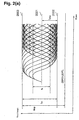
- Fig. 2(a) shows a schematic view of a retrieving waveform (an eye pattern) of EFM modulation signals to be used for a CD family including CD-RW.
- This eye pattern all retrieving waveforms of amorphous marks and spaces in crystalline state, of from 3T to 11T, are randomly contained.
- the retrieving waveforms are waveforms as observed on an oscilloscope when the reflected light intensities are taken out as voltage signals. In such a case, the retrieving signals contain a direct current component.
- top value R top of reflectivity corresponding to a space One having the top I top of the eye pattern converted to a reflectivity to an incident light is the top value R top of reflectivity corresponding to a space, and one having the amplitude I 11 of the eye pattern (for practical purpose, the amplitude of 11T mark) normalized by I top , is the modulation m 11 of the eye pattern of a record signal represented by the following formula (1) (in this specification, m 11 may sometimes be referred to simply as a modulation).
- m 11 I 11 /I top ⁇ 100 (%)
- the modulation m 11 is from 60% to 80%.
- the modulation depends upon the optical resolution and tends to be observed to be large by an optical system having a high NA. Therefore, in the present invention, a modulation m 11 is taken when recording is carried out by irradiating a laser beam having a wavelength of about 780 nm through an optical system having a numerical aperture NA of 0.5.
- the wavelength is not required to be strictly 780 nm, and it may be within a range of from about 775 to 795 nm.
- the higher the signal amplitude I 11 the better.
- the upper limit of m 11 is 80%, preferably 78%, more preferably about 75%.
- the signal-to-noise ratio (SN ratio) tends to be low, and accordingly, the lower limit is 60%, preferably 62%, more preferably about 65%.
- R top is within a range of from 15 to 25%, preferably from 15 to 20%, more preferably from 16 to 19%.
- I slice is the potential difference between the centerline 2001 of I and the bottom 2002 of the envelope curve in Fig. 2(a)
- I 11 is a voltage between the top 2003 and the bottom 2002 of the envelop curve.
- the jitter is preferably such that when retrieving is carried out at 1-time velocity (the reference clock period: 231 nsec), the jitter value is at most 35 nsec, preferably at most 30 nsec, more preferably at most 25 nsec.
- jitter of 3T mark length or space length tends to have the worst value among 3T to 11T in many cases. Further, jitter of 3T space length tends to have a worse value than jitter of 3T mark in many cases.
- the deviation is usually at most ⁇ 40 nsec with 3T and at most ⁇ 60 nsec with 11T. Further, with respect to 4T to 10T, the deviation will be a value obtained by complementing at most ⁇ 40 nsec and at most ⁇ 60 nsec as prescribed for 3T and 11T. In any case, the deviation is acceptable if it is within a range of about ⁇ 20% of the reference clock period T.
- a medium recorded at a high velocity at a level of at least 24-times velocity can be retrieved by a retrieving system for conventional CD-RW, while maintaining interchangeability with conventional CD-RW standards.
- the rewritable optical recording medium of the present invention it is preferred that in the recording at a linear velocity of 24-times velocity, when a simple periodic signal comprising a 3T mark (a mark having a time length of 3T, where T is the data reference clock period) and a 3T space (a space between marks, having a time length of 3T), is recorded, and then, a simple periodic signal comprising a 11T mark (a mark having a time length of 11T) and a 11T space (a space between marks, having a time length of 11T), is overwritten, the erase ratio of the 3T mark is at least 20 dB. Such erase ratio is more preferably at least 25 dB.
- such erase ratio is at least 20 dB, more preferably at least 25 dB.
- the higher such erase ratio at a high linear velocity the higher the recrystallization speed at the time of erasing amorphous marks, whereby with such a medium, overwriting of EFM signals at a high linear velocity is possible.
- such erase ratio at 32-times velocity is set to be at least 20 dB, it is not only possible to obtain good characteristics when used at 32-times velocity, but also possible to obtain good characteristics also when used at less than 24-times velocity.
- a recording method of the after-mentioned recording method CD1-1 or 1-2 is employed.
- a 3T mark is recorded by a writing power comprising one writing pulse Pw and a subsequent off-pulse Pb (0 ⁇ Pb ⁇ 1mW), and at other sections, an erasing power Pe is irradiated.
- Pw is a power to melt the recording layer
- Pb is a cooling power to quench the melted region to form an amorphous state.
- a 11T mark is recorded by repeating a writing power comprising five writing pulses Pw and off-pulses Pb (0 ⁇ Pb ⁇ 1mW) accompanying individual Pw, and at other sections, an erasing power Pe is irradiated.
- a writing power comprising five writing pulses Pw and off-pulses Pb (0 ⁇ Pb ⁇ 1mW) accompanying individual Pw, and at other sections, an erasing power Pe is irradiated.
- the same Pe and Pw are used, and the Pe dependency of the erase ratio is measured by changing Pe while maintaining Pe/Pw to be constant within a range of from 0.2 to 0.6, to confirm that at some Pe, the erase ratio becomes at least 20 dB, preferably at least 25 dB.
- the erase ratio is one obtained by measuring the decrease of the carrier level of 3T data between before and after the overwriting of the 11T data, by dB unit.
- recording is carried out in the same groove, and usually, recording is carried out in a groove corresponding to one round.
- the time for irradiation of the recording layer with a laser beam having a wavelength of ⁇ focused by an object lens having a numerical aperture NA moving at a linear velocity V is normalized by ⁇ /(NA ⁇ V), whereby the irradiation time increases as the linear velocity is low, and the time required for recrystallization can sufficiently be secured.
- the method for measuring the erase ratio there may be a case where the reduction of the carrier level of the recorded marks is measured by a decibel value, while irradiating an erasing power Pe in a direct current (DC) fashion, and this is called a DC erase ratio.
- a DC erase ratio In the measurement of the DC erase ratio, an erase ratio is employed in a case where the maximum erase ratio can be obtained while Pe is variable. As compared with the above-mentioned overwriting erase ratio, it may sometimes take a higher value by from 1 to 2 dB. If such a correction value is taken into consideration, the measurement of the overwriting erase ratio may be substituted by the measurement of the DC erase ratio.
- the archival life of the recording medium is represented by the time until the jitter of record signals previously recorded will reach 35 nsec (nano seconds) in retrieving at 1-time velocity
- the archival life at a temperature of 80°C under a relative humidity of 85% is preferably at least 200 hours, more preferably at least 500 hours.
- each of the modulation m 11 and the top value R top of reflectivity in a crystalline state maintains preferably at least 80%, more preferably at least 90% of the initial value even upon expiration of 3 hours in the accelerated test environment at a temperature of 105°C, because such a requirement is satisfied by currently commercially available CD-RW for from 1 to 4-time velocity.
- the crystallization temperature of the recording layer which will be described hereinafter, can be made to be at least about 150°C.
- V represents a linear velocity of 24-times velocity or 32-times velocity
- V 1 is a reference velocity (1-time velocity) which is set to be a linear velocity of 1.2 m/s
- T 1 is 231 nsec
- ⁇ i ( ⁇ i + ⁇ i ) or the like means to take the sum from 1 to m with respect to i.
- the modulation m 11 , R top , the jitter of each mark or space between marks, the deviation, the asymmetry value and the value of the erase ratio will be within the above-mentioned numerical value ranges.
- V min is a linear velocity of any one selected from 8-times velocity, 10-times velocity, 12-times velocity, 16-times velocity and 20-times velocity
- V max is a linear velocity of either 24-times velocity or 32-times velocity
- the modulation m 11 , R top , the jitter, the deviation, the asymmetry value and the value of the erase ratio will be within the above numerical value ranges, whereby recording by the after-mentioned P-CAV or CAV system will be possible.
- j and k may take different values for every n.
- Pw, Pb and Pe are at constant power levels, and Pb ⁇ Pe ⁇ Pw.
- recording of an EFM random pattern is carried out wherein while maintaining the Pe/Pw ratio to be constant at a level between 0.2 and 0.6, Pw is changed between 20 and 40 mW, so that at Pw where the best characteristics can be obtained, the above-mentioned respective values of the jitters of the respective mark lengths and the respective spaces between marks, m 11 and R top , may be satisfied.
- the power values Pw, Pe, Pb, etc. are meant to be powers of the main beams among the recording laser beams and exclude powers which are classified to be beams not directly related to the recording, like a servo beam for a servo operation in a so-called three beam method.
- the Pe/Pw ratio firstly a value between 0.3 and 0.4 is employed, and as a result, if the above requirements for m 11 , R top , the asymmetry, the deviation, etc. are not satisfied, a value between 0.2 and 0.3, or between 0.3 and 0.6, is employed.
- the laser beam power level at each of recording pulse sections ⁇ i T and ⁇ i 'T and off-pulse sections ⁇ i T and ⁇ i ' T is constant at Pw for the recording pulse sections and at Pb for the off-pulse sections.
- Pw and Pb are defined by average powers at such sections.
- unavoidable overshooting or undershooting due to a response of a laser diode is allowable.
- the rising or falling of the recording pulses ⁇ i T and ⁇ i 'T is at most about 3 nsec, but preferably from 1 nsec to 2 nsec.
- Recording methods CD1-1 and 1-2 are ones having a further study added to a record pulse-dividing method as disclosed in JP-A-2001-331936 wherein a recording pulse (Pw irradiation section) and an off-pulse (Pb irradiation section) are alternately generated in repeated periods having period 2T as the base.
- a recording pulse Pw irradiation section
- an off-pulse Pb irradiation section
- a record pulse-dividing method which is particularly suitable for CD-RW overwritable at 24- or 32-times velocity and which is particularly industrially useful, economical and simple, has been found.
- the recording pulse strategy of the present invention it is possible to provide a recording medium and a recording method therefor, whereby the record quality can easily be maintained even when recorded by a plurality of drives and interchangeability can easily be secured.
- variable parameters and their ranges in the record pulse-dividing method using period 2T as the base are defined.
- the minimum parameters required to maintain a good record quality at 24-times velocity or 32-times velocity have been found, and they are used as variable. If the number of variable parameters is increased, it becomes relatively easy to accomplish good recording at 24-times velocity or 32-times velocity.
- the minimum parameters have been found which make it possible to realize CD-RW capable of carrying out 24-times velocity recording or 32-times velocity recording while simplifying the design of the electronic circuit (integrated circuit).
- the minimum parameters to be variable to carry out good recording at 24-times velocity or 32-times velocity can be realized for the first time by carrying out a study on a recording medium overwritable at 24-times velocity or 32-times velocity and a study on a pulse-dividing recording method, while feeding back the respective knowledges mutually.
- the present invention has been accomplished by a high level of creation such that the recording medium and the recording method are simultaneously realized.
- the definitions as shown by recording methods CD1-1 and 1-2, are adopted.
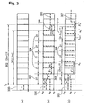
- Fig. 3 is a graph showing one embodiment of the relation of the respective recording pulses in a case where the pulse-dividing methods according to the above-mentioned recording methods CD1-1 and 2-1 are to be carried out.
- the time widths of recording pulses and off-pulses to form mark lengths 2 mT should formally be represented by ⁇ 1 T, ⁇ 1 T, ⁇ cT, ... ⁇ m T, ⁇ m T, but for the sake of simple clear representation of the graph, in Fig. 3(b), they are simply represented by ⁇ 1 , ⁇ 1 , ⁇ c, ... ⁇ m , ⁇ m , i.e. by omitting the indication of the reference clock period T.
- Fig. 3(c) the time widths of recording pulses and off-pulses to form mark lengths 2 mT.
- correction of mark length difference 1T between an even number length mark and an odd number length mark for the same division number m is divided and allocated to an off-pulse section ⁇ 1 T next to the forefront recording pulse and to a recording pulse periodic section ( ⁇ m-1 + ⁇ m ) T second from the last. Namely, the correction of mark length 1T is carried out by adjustment of off-pulse lengths ⁇ 1 T and ⁇ m-1 T, and pulse ⁇ m T of the last recording pulse section.
- 300 represents the reference clock of period T.
- symbol 301 corresponds to the length of a record mark having a length of 2mT
- symbol 302 corresponds to the length of a record mark having a length of (2m+1)T.
- a case where m 5, is shown.
- n is an even number
- at sections 304 excluding the forefront recording pulse and the last off-pulse i.e. sections excluding 305 and 306 in Fig. 3
- section ( ⁇ 1 + ⁇ 2 )T and section ( ⁇ m-1 + ⁇ m )T are respectively increased or reduced by about 0.5T to adjust their lengths. Due to an influence of heat interference, etc., such a value may not precisely be 0.5T, but will generally be within a range of from 0.3T to 0.6T.
- ⁇ m is made to be larger than 0 ( ⁇ m >0) to make ⁇ m ⁇ m '.
- ⁇ m-1 and ⁇ m are made to have substantially equal values. If ⁇ m-1 and ⁇ m are made to be substantially equal, it will be possible to simplify the design of the electronic circuit (integrated circuit) to control generation of laser beams (pulsed beams) for recording pulses and off-pulses in a recording pulse strategy, while maintaining good jitter characteristics.
- ⁇ 1 and ⁇ mm will take a value of from 0.3 to 0.6.
- the values of ⁇ m-1 and ⁇ m are determined depending upon how ⁇ mm is divided and distributed, whereby ⁇ m-1 may take a value of from 0 to 0.6, and ⁇ m may take a value of more than 0 and at most 0.6.
- ⁇ 1 and ⁇ mm may be made to be 0.6, but ⁇ m-1 and ⁇ m are preferably made to be a value of at most 0.5.
- ⁇ 1 ' ⁇ 1
- ⁇ m ' ⁇ m
- ⁇ m and ⁇ m ' are also constant irrespective of m.
- ⁇ 1 ( ⁇ 1 ') is from 0.7 to 1.4
- ⁇ c is from 0.7 to 1.2
- ⁇ m is from 0.7 to 1.2.
- ⁇ 1 and ⁇ m firstly the same value as ⁇ c is employed, and then, fine adjustment is carried out within a range of about 0.3 at the maximum.
- ( ⁇ 1 '+ ⁇ 2 ')T is made to be longer by about 1T than ( ⁇ 1 + ⁇ 2 )T.
- ⁇ 1 , ⁇ 1 ', ⁇ 2 , ⁇ 2 ', ⁇ 2 and ⁇ 2 ' are made to be equal to ⁇ 1 , ⁇ 1 ', ⁇ m , ⁇ m ', ⁇ m and ⁇ m ' in the case where m is 3, respectively, ⁇ 1 is made to be equal to either ⁇ 1 or ⁇ m-1 in the case where m is 3, and ⁇ 1 ' is made to be equal to either ⁇ 1 ' or ⁇ m-1 ' in the case where m is 3.
- a deviation at a level of ⁇ 10% is allowable.
- a recording pulse row 303 shown by a dotted line in Fig. 3(b) is obtained, and for an odd number length mark, a recording pulse row 307 shown by a dotted line in Fig. 3(c) is obtained.
- ⁇ 1 ' is made to be larger by from about 0.1 to 1.5 than ⁇ 1 ' in the case where m is at least 2, and ⁇ 1 ' is made to be smaller than ⁇ 1 ' and to be the same as or larger than ⁇ m and ⁇ m ' in the case where m is at least 2. Further, the range of ⁇ 1 ' is preferably from 0 to 2.
- Fig. 16 is a graph showing one embodiment of the relation of the respective recording pulses in a case where the pulse-dividing methods according to the above-mentioned recording methods CD1-2 and 2-2 are to be carried out.
- the time widths of recording pulses and off-pulses to form mark lengths 2 mT should formally be represented by ⁇ 1 T, ⁇ 1 T, ⁇ cT, ... ⁇ m T, ⁇ m T, but for the sake of simple clear representation of the graph, in Fig. 16(b), they are simply represented by ⁇ 1 , ⁇ 1 , ⁇ c, ... ⁇ m , ⁇ m , i.e. the indication of the reference clock period T is omitted.
- correction of mark length difference 1T between an even number length mark and an odd number length mark for the same division number m is divided and allocated to a recording pulse periodic section ( ⁇ m-1 + ⁇ m )T second from the last and the last off-pulse ⁇ m T. Namely, the correction of mark length 1T is carried out by adjustment of off-pulse lengths ⁇ m-1 T and ⁇ m T, and pulse ⁇ m T of the last recording pulse section.
- recording pulses and off-pulses to be changed as between even number and odd number marks are concentrated at the rear end portion of a mark, whereby there is not only a merit in that the rear end jitter of a record mark can easily be controlled, but also a merit in that the design of an electronic circuit (integrated circuit) to control generation of laser beams (pulsed beams) for recording pulses and off-pulses of the recording pulse strategy can be simplified. Further, there is a merit that the number of parameters to be variable is small.
- 400 represents the reference clock of period T.
- symbol 401 corresponds to the length of a record mark having a length of 2mT
- symbol 402 corresponds to the length of a record mark having a length of (2m+1)T.
- a case where m 5, is shown.
- n is an even number
- section ( ⁇ m-1 + ⁇ m )T is increased or reduced by about 1T to adjust its length. Due to an influence of heat interference, etc., such a value may not precisely be 1T, but will generally be within a range of from 0.5 to 1.2T.
- ⁇ m and ⁇ m ' are individually finely adjusted.
- ⁇ mm takes a value of from 0.5 to 1.2.
- ⁇ m-1 and ⁇ m may, respectively, take a value of from 0 to 0.6 depending upon how ⁇ mm is divided and distributed.
- ⁇ m-1 may be zero, ⁇ m is made larger than 0 so that ⁇ m ⁇ m '.
- ⁇ m-1 and ⁇ m are made to have substantially equal values.
- ⁇ m-1 and ⁇ m are made to be substantially equal, it will be possible to simplify the design of an electronic circuit (integrated circuit) to control generation of pulsed beams, while maintaining good jitter characteristics.
- ⁇ 1 and ⁇ m firstly, the same value as ⁇ c is employed, and fine adjustment is carried out within a range of larger by about 0.3 at the maximum than ⁇ c.
- ⁇ m and ⁇ m-1 take about 0.4 as the initial value, and fine adjustment is carried out to obtain the prescribed mark lengths. Further, ⁇ m ' at section 410 is firstly made to be equal to ⁇ m at section 405, and thereafter, fine adjustment is carried out.
- ( ⁇ 1 '+ ⁇ 2 ')T is made longer by about 1T than ( ⁇ 1 + ⁇ 2 )T.
- ⁇ 1 , ⁇ 1 ', ⁇ 1 , ⁇ 1 ', ⁇ 2 , ⁇ 2 ', ⁇ 2 and ⁇ 2 ' may further be finely adjusted within a range of about ⁇ 10%.
- recording pulse train 402 shown by a dotted line in Fig. 16(b) is obtained, and for an odd number length mark, recording pulse train 406 shown by a dotted line in Fig. 16(c) is obtained.
- ⁇ 1 ' is preferably made to larger by from about 0.1 to 1.5 than ⁇ 1 ' in the case where m is at least 2. Further, the range of ⁇ 1 ' is preferably from 0 to 2.
- recording method CD2-1 an even number length mark and an odd number length mark are recorded by the same rule as in recording method CD1-1
- ⁇ ' m is made to be variable within a range of from 0 to 1.
- ⁇ m-1 + ⁇ m + ⁇ m ' is preferably made to be within a range of from 0.5 to 1.5.
- ⁇ is a real number within a range of from 0.8 to 1.5. Particularly, a value within a range of from 1.0 to 1.3 is firstly employed, and thereafter, measurement is carried out by enlarging the range to be from 0.8 to 1.5.
- ⁇ 1 , ⁇ 1 ', ⁇ 2 , ⁇ 2 ', ⁇ 2 and ⁇ 2 ' are made to be equal to ⁇ 1 , ⁇ 1 ', ⁇ 3 ( ⁇ m ), ⁇ 3 ' ( ⁇ m '), ⁇ 3 ( ⁇ m ) and ⁇ 3 ' ( ⁇ m ') in the case where m is 3, respectively, ⁇ 1 is made to be equal to either ⁇ 1 or ⁇ 2 ( ⁇ m-1 ) in the case where m is 3, and ⁇ 1 ' is made to be equal to either ⁇ 1 ' or ⁇ 2 ' ( ⁇ m-1 ') in the case where m is 3.
- the recording characteristics are defined for example at 10-times velocity and 24-times velocity, or at 12-times velocity and 24-times velocity, and with respect to CD-RW expected to be used at a velocity of up to 32-times velocity, the recording characteristics at 10-times velocity and 32-times velocity, the recording characteristics at 12-times velocity and 32-times velocity, or the recording characteristics at 16-times velocity and 32-times velocity, are, respectively, defined, whereby a medium suitable for the after-mentioned CAV recording system, P-CAV recording system or ZCLV recording system, can substantially univocally be defined from the viewpoint of recording/retrieving interchangeability among drives.
- a preferred method also with a view to securing recording/retrieving interchangeability of a medium from the viewpoint of recording drives. It is particularly preferred to use recording method CD1-1 in combination with recording method CD2-1, and to use recording method CD1-2 in combination with recording method CD2-2.
- recording method CD1-2 with recording method CD2-2 to define rewritable CD-RW with the maximum linear velocity V max of 24-times velocity or 32-times velocity.
- interchangeability can be secured when such a medium is subjected to recording by a plurality of recording devices.
- ⁇ m-1 ' 1+ ⁇ m0 (0 ⁇ m0 ⁇ 0.6)
- ⁇ m ' 1+ ⁇ m0 (0 ⁇ m0 ⁇ 0.6)
- ⁇ m ' ⁇ m + ⁇ m '
- ⁇ c is from 0.7 to 1.2, more preferably from 0.7 to 1, particularly preferably from 0.9 to 1.
- recording method CD1-3 with the following recording method CD2-3 to define rewritable CD-RW to be used at the maximum linear velocity V max of 24-times velocity or 32-times velocity.
- Recording methods CD1-3 and 2-3 are characterized in that when an odd number record mark is to be formed among an even number record mark and an odd number record mark having the same division number m, equal ⁇ m (which is represented by ⁇ m0 in recording methods CD1-3 and 2-3) is imparted to an off-pulse section ( ⁇ m-1 ') immediately before the last and to the last recording pulse section ( ⁇ m ').
- ⁇ m which is represented by ⁇ m0 in recording methods CD1-3 and 2-3
- ⁇ m which is represented as ⁇ m0 in recording methods CD1-3 and 2-3
- the design of an electronic circuit (integrated circuit) to control generation of laser beams (pulsed beams) for recording pulses and off-pulses of the recording pulse strategy for forming record marks can be simplified, whereby it will be possible to reduce the costs for the electronic circuit (integrated circuit).
- ⁇ m larger than 0 with a view to stabilizing the shape of the rear end portion of the record mark to improve the jitter characteristics.
- ⁇ m0 is made to be within a range of 0 ⁇ m0 ⁇ 0.5.
- ⁇ m ' is preferably set to be within a range of 0 ⁇ m ' ⁇ 1, more preferably 0 ⁇ m ' ⁇ 0.6, particularly preferably within a range of 0 ⁇ m ' ⁇ 0.5.
- Pw whereby m 11 would be within a range of from 0.6 to 0.8, is determined to obtain the initial value Pw a .
- Pw value whereby m 11 would be about 0.7, is taken as the initial value Pw a .
- Pe is irradiated in a direct current fashion to the 11T data signals recorded by such Pw a , to measure the decrease of the carrier level of the 11T data signals by dB (decibel value).
- the initial value Pb a of Pb a power equivalent to a retrieving laser beam power at a level where servo will be stabilized at the time of retrieving with a power of 0 ⁇ Pb a ⁇ 1 mW, is selected.
- overwriting usually means to overwrite new data without returning once-recorded data to a uniform unrecorded or erased state by a certain specific treatment.
- overwriting ten times in the case of evaluating the characteristics of an optical recording medium by means of the above recording method CD1-1, 1-2, 2-1 or 2-2, means to carry out the first recording (overwriting first time) in the initial crystalline state and then carry out overwriting 9 times. The same applies in the following description.
- the wavelength of the recording laser beam in recording methods CD1-1, 1-2, 2-1 and 2-2 is fluctuated within a range of from about 775 to 795 nm, such will not be a serious problem, since with a phase-change medium, the wavelength dependency within such a wavelength range is very small.
- a rewritable optical recording medium of the present invention is usually of a disk-shape. And, a portion in a crystalline state of the phase-change type recording layer is in an unrecorded or erased state, and a portion in an amorphous state is in a recorded state.
- Information to be recorded comprises signals EFM+ modified by irradiating a recording beam such as a laser beam to form amorphous marks.
- a usually helical groove is formed on the substrate of the medium. The amorphous marks are usually formed in this groove.
- the groove is meant for a bottom of a recess for guiding a laser beam, formed on the substrate surface, which is a face closer as viewed from the incident side of the recording/retrieving laser beam.
- the reference clock period T When data are to be recorded, the reference clock period T will be a reference, and data will be recorded by forming marks and spaces (between marks) having various time lengths corresponding to integral multiple lengths of the reference clock period. In EFM+ modulation, marks having time lengths of from 3T to 14T are usually formed. Further, it is common that the reference clock period T is changed in inverse proportion to the recording linear velocity.
- the inverse number of the reference clock period T is called a reference clock frequency
- the reference clock frequency at 1-time velocity of DVD corresponds to 1 channel bit of data and is usually 26.15625 MHz.
- the product VT of the reference clock period T and the linear velocity V is constant irrespective of the linear velocity, unless otherwise specified.
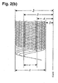
- Fig. 2(b) shows a schematic view of a retrieving waveform (an eye pattern) of EFM+ modified signals to be used for a DVD family including DVD-RW.
- This eye pattern all retrieving waveforms of amorphous marks and spaces in crystalline state, of from 3T to 14T, are randomly contained.
- the retrieving waveforms are waveforms as observed on an oscilloscope when the reflected light intensities are taken out as voltage signals. In such a case, the retrieving signals contain a direct current component.
- One having the top I 14H of the eye pattern converted to a reflectivity to an incident light is the top value R top of reflectivity corresponding to a space, and one having the amplitude I 14 of the eye pattern (for practical purpose, the amplitude of 14T mark) normalized by I 14H , is the modulation m 14 of a record signal represented by the following formula (DVD1) (in this specification, m 14 may sometimes be referred to simply as a modulation).
- VD1 the modulation m 14 of a record signal represented by the following formula (DVD1) (in this specification, m 14 may sometimes be referred to simply as a modulation).
- M 14 I 14 /I 14H ⁇ 100 (%)
- the modulation m 14 is from 55% to 80%.
- the wavelength is not required to be strictly 650 nm, and it may be within a range of from about 630 to 665 nm.
- the higher the signal amplitude I 14 the better.
- the upper limit of m 14 is 80%, preferably 78%, more preferably about 75%.
- the signal-to-noise ratio (SN ratio) tends to be low, and accordingly, the lower limit is 55%, preferably 60%, more preferably about 65%.
- R top is within a range of from 18 to 30%, preferably from 18 to 25%, more preferably from 19 to 23%.
- Clock jitter of retrieving signals is one obtained by normalizing by the reference clock period T a standard deviation (jitter) of the difference in time against PLL clock of the leading edge and the trailing edge of binary signals obtained by passing the retrieving signals through an equalizer and LPF, followed by conversion to binary signals by a slicer.
- T standard deviation
- a detailed measurement method is prescribed in DVD-ROM standards or DVD+RW standards.
- the clock jitter value when retrieving is carried out 1-time velocity (reference clock period: 38.2 nsec) is at most 15%.
- this clock jitter is stipulated to be at most 9%, but in the present invention, up to 15% is taken as an allowable value, taking into consideration the improvement in performance of the DVD retrieving circuit in recent years.
- This clock jitter value is more preferably at most 12%, further preferably at most 10%.
- a medium recorded at a high velocity at a level of at least 6-times velocity can be retrieved by a retrieving system for conventional phase-change type DVD, while maintaining interchangeability with conventional phase-change type DVD standards.
- the clock jitter in RW-DVD may sometimes be referred to simply as jitter.
- a simple periodic signal (referred to as 3T data) comprising a 3T mark and a 3T space (a space between mark), is recorded, and then, a simple periodic signal (referred to as 14T data) comprising a 14T mark and a 14T space, is overwritten, the erase ratio of the 3T mark is at least 20 dB, preferably at least 25 dB. Further, also at 12-times velocity, such erase ratio is preferably at least 20 dB, more preferably at least 25 dB.
- a 3T mark is recorded by a writing power comprising one writing pulse Pw and a subsequent off-pulse Pb (0 ⁇ Pb ⁇ 1mW), and at other sections, an erasing power Pe is irradiated.
- Pw is a power to melt the recording layer
- Pb is a cooling section to quench the melted region to form an amorphous state.
- a 14T mark is recorded by repeating a writing power comprising seven writing pulses Pw and off-pulses Pb (0 ⁇ Pb ⁇ 1mW accompanying individual Pw, and at other sections, an erasing power Pe is irradiated.
- a writing power comprising seven writing pulses Pw and off-pulses Pb (0 ⁇ Pb ⁇ 1mW accompanying individual Pw, and at other sections, an erasing power Pe is irradiated.
- the same Pe and Pw are used, and the Pe dependency of the erase ratio is measured by changing Pe while maintaining Pe/Pw to be constant within a range of from 0.2 to 0.6, to confirm that at some Pe, the erase ratio becomes at least 20 dB, preferably at least 25 dB.
- the erase ratio is one obtained by measuring the decrease of the carrier level of 3T data between before and after the overwriting of the 14T data, by dB unit.
- recording is carried out in the same groove, and usually, recording is carried out in a groove corresponding to one round.
- the erase ratio With respect to the erase ratio, if the erase ratio is sufficient at the upper limit within the linear velocity range for overwriting, there will be no possibility that the erase ratio becomes deficient on a lower linear velocity side than usual. Namely, the time for irradiation of the recording layer with a laser beam having a wavelength of ⁇ condensed by an object lens having a numerical aperture NA moving at a linear velocity V, is standardized by ⁇ /(NA ⁇ V), whereby the irradiation time increases as the linear velocity is low, and the time required for recrystallization can sufficiently be secured.
- the archival life of the recording medium is represented by the time until the jitter of record signals previously recorded will reach 12% in retrieving at 1-time velocity
- the archival life at a temperature of 80°C under a relative humidity of 85% is preferably at least 200 hours, more preferably at least 500 hours.
- each of the modulation m 14 and the top value R top of reflectivity in a crystalline state maintains preferably at least 90% of the initial value even upon expiration of 3 hours in the accelerated test environment at a temperature of 105°C, because such a requirement is satisfied by currently commercially available DVD+RW for from 1 to 2.4-time velocity.
- V represents a linear velocity of 6-times velocity, 8-times velocity, 10-times velocity or 12-times velocity
- V 1 is a reference velocity (1-time velocity) which is set to be a linear velocity of 3.49 m/s
- T 1 is 38.2 nsec
- ⁇ i ( ⁇ i + ⁇ i ) or the like means to take the sum from 1 to m with respect to i.
- the modulation m 14 , R top , the jitter, the asymmetry value and the value of the erase ratio will be within the above-mentioned numerical value ranges.
- V min is a linear velocity of any one selected from 2-times velocity, 2.5-times velocity, 3-times velocity, 4-times velocity and 5-times velocity, of the above-mentioned reference velocity
- V max is 6-times velocity, 8-times velocity, 10-times velocity or 12-times velocity, of the reference velocity
- the modulation m 14 , R top , the jitter, the asymmetry value and the value of the erase ratio will be within the above numerical value ranges, whereby recording by the after-mentioned P-CAV or CAV system will be possible.
- j and k may take different values for every n.
- Pw, Pb and Pe are at constant power levels, and Pb ⁇ Pe ⁇ Pw.
- recording of an EFM+ random pattern is carried out wherein while maintaining the Pe/Pw ratio to be constant at a level between 0.2 and 0.6, Pw is changed between 10 and 40 mW, so that at Pw where the best characteristics can be obtained, the above-mentioned respective values of the jitters, m 14 and R top , may be satisfied.
- a value between 0.3 and 0.4 is employed, and as a result, if the above requirements for m 14 , R top , the asymmetry, etc. are not satisfied, a value between 0.2 and 0.3, or between 0.3 and 0.6, is employed.
- the laser beam power level at each of recording pulse sections ⁇ i T and ⁇ i 'T and off-pulse sections ⁇ i T and ⁇ i 'T is constant at Pw for the recording pulse sections and at Pb for the off-pulse sections.
- Pw and Pb are defined by average powers at such sections.
- unavoidable overshooting or undershooting due to a response of a laser diode is allowable.
- the rising or falling of the recording pulses ⁇ i T and ⁇ i 'T is at most about 2 nsec, but preferably from 1 nsec to 2 nsec.
- Recording methods DVD1-1 and 1-2 are ones having a further study added to a record pulse-dividing method as disclosed in JP-A-2001-331936 wherein a recording pulse (Pw irradiation section) and an off-pulse (Pb irradiation section) are alternately generated in repeated periods having period 2T as the base.
- a recording pulse Pw irradiation section
- an off-pulse Pb irradiation section
- a record pulse-dividing method which is particularly suitable for phase-change type rewritable DVD overwritable at 6- to 12-times velocity and which is particularly industrially useful, economical and simple, has been found.
- the recording pulse strategy of the present invention it is possible to provide a recording medium and a recording method therefor, whereby the record quality can easily be maintained even when recorded by a plurality of drives and interchangeability can easily be secured.
- variable parameters and their ranges in the record pulse-dividing method using period 2T as the base are defined.
- the minimum parameters required to maintain a good record quality at 6-times velocity to 12-times velocity have been found, and they are used as variable. If the number of variable parameters is increased, it becomes relatively easy to accomplish good recording at 6-times velocity to 12-times velocity.
- the minimum parameters have been found which make it possible to accomplish good recording at 6-times velocity to 12-times velocity while simplifying the design of the electronic circuit (integrated circuit).
- the minimum parameters to be variable to carry out good recording at 6-times velocity to 12-times velocity can be realized for the first time by carrying out a study on a recording medium overwritable at 6-times velocity to 12-times velocity and a study on a pulse-dividing recording method, while feeding back the respective knowledges mutually.
- the present invention has been accomplished by a high level of creation such that the recording medium and the recording method are simultaneously realized.
- the definitions as shown by recording methods DVD1-1 and 1-2 are adopted.
- Fig. 3 is a graph showing one embodiment of the relation of the respective recording pulses in a case where the pulse-dividing methods according to the above-mentioned recording methods DVD1-1 and 2-1 are to be carried out.
- the time widths of recording pulses and off-pulses to form mark lengths 2 mT should formally be represented by ⁇ 1 T, ⁇ 1 T, ⁇ cT, ... ⁇ m T, ⁇ m T, but for the sake of simple clear representation of the graph, in Fig. 3(b), they are simply represented by ⁇ 1 , ⁇ 1 , ⁇ c, ... ⁇ m , ⁇ m , i.e. the indication of the reference clock period T is omitted.
- n in nT mark is an odd number or an even number.
- Correction of mark length difference 1T between an even number length mark and an odd number length mark for the same division number m is divided and allocated to an off-pulse section ⁇ 1 T next to the forefront recording pulse and a recording pulse periodic section ( ⁇ m-1 + ⁇ m ) T second from the last .
- the correction of mark length 1T is carried out by adjustment of off-pulse lengths ⁇ 1 T and ⁇ m-1 T, and pulse ⁇ m T of the last recording pulse section.
- 300 represents the reference clock of period T.
- symbol 301 corresponds to the length of a record mark having a length of 2mT
- symbol 302 corresponds to the length of a record mark having a length of (2m+1)T.
- a case where m 5, is shown.
- n is an even number
- at sections 304 excluding the forefront recording pulse and the last off-pulse i.e. sections excluding 305 and 306 in Fig. 3
- section ( ⁇ 1 + ⁇ 2 )T and section ( ⁇ m-1 + ⁇ m )T are respectively increased or reduced by about 0.5T to adjust their lengths. Due to an influence of heat interference, etc., such a value may not precisely be 0.5T, but will generally be within a range of from 0.3T to 0.6T.
- ⁇ m is made to be larger than 0 ( ⁇ m >0) to make ⁇ m ⁇ m '.
- ⁇ m-1 and ⁇ m are made to have substantially equal values. If ⁇ m-1 and ⁇ m are made to be substantially equal, it will be possible to simplify the design of the electronic circuit (integrated circuit) to control generation of laser beams (pulsed beams) for recording pulses and off-pulses in a recording pulse strategy, while maintaining good jitter characteristics.
- ⁇ 1 and ⁇ mm will take a value of from 0.3 to 0.6.
- the values of ⁇ m-1 and ⁇ m are determined depending upon how ⁇ mm is divided and distributed, whereby ⁇ m-1 may take a value of from 0 to 0.6, and ⁇ m may take a value of more than 0 and at most 0.6.
- ⁇ 1 , ⁇ m-1 , ⁇ m and ⁇ mm may be made to be 0.6, but ⁇ 1 , ⁇ m-1 and ⁇ m are preferably made to be a value of at most 0.5.
- ⁇ 1' ⁇ 1
- ⁇ m ' ⁇ m
- ⁇ m and ⁇ m ' are also constant irrespective of m.
- ⁇ 1 ( ⁇ 1 ') is from 0.7 to 1.4
- ⁇ c is from 0.7 to 1.2
- ⁇ m is from 0.7 to 1.2.
- ⁇ 1 and ⁇ m firstly the same value as ⁇ c is employed, and then, fine adjustment is carried out within a range of about 0.3 at the maximum.
- ( ⁇ 1 '+ ⁇ 2 ')T is made to be longer by about 1T than ( ⁇ 1 + ⁇ 2 )T.
- ⁇ 1 , ⁇ 1 ', ⁇ 2 , ⁇ 2 ', ⁇ 2 and ⁇ 2 ' are made to be equal to ⁇ 1 , ⁇ 1 ', ⁇ m , ⁇ m ', ⁇ m and ⁇ m ' in the case where m is 3, respectively, ⁇ 1 is made to be equal to either ⁇ 1 or ⁇ m-1 in the case where m is 3, and ⁇ 1 ' is made to be equal to either ⁇ 1 ' or ⁇ m-1 ' in the case where m is 3.
- a deviation at a level of ⁇ 10% is allowable.
- a recording pulse row 303 shown by a dotted line in Fig. 3(b) is obtained, and for an odd number length mark, a recording pulse row 307 shown by a dotted line in Fig. 3(c) is obtained.
- ⁇ 1 ' is made to be larger by from about 0.1 to 1.5 than ⁇ 1 ' in the case where m is at least 2, and ⁇ 1 ' is made to be smaller than ⁇ 1 ' and to be the same as or larger than ⁇ m and ⁇ m ' in the case where m is at least 2. Further, the range of ⁇ 1 ' is preferably from 0 to 2.
- Fig. 16 is a graph showing one embodiment of the relation of the respective recording pulses in a case where the pulse-dividing methods according to the above-mentioned recording methods DVD1-2 and 2-2 are to be carried out.
- the time widths of recording pulses and off-pulses to form mark lengths 2 mT should formally be represented by ⁇ 1 T, ⁇ 1 T, ⁇ cT, ... ⁇ m T, ⁇ m T, but for the sake of simple clear representation of the graph, in Fig. 16(b), they are simply represented by ⁇ 1 , ⁇ 1 , ⁇ c, ... ⁇ m , ⁇ m , i.e. the indication of the reference clock period T is omitted.
- correction of mark length difference 1T between an even number length mark and an odd number length mark for the same division number m is divided and allocated to a recording pulse periodic section ( ⁇ m-1 + ⁇ m )T second from the last and the last off-pulse ⁇ m T. Namely, the correction of mark length 1T is carried out by adjustment of off-pulse lengths ⁇ m-1 T and ⁇ m T, and pulse ⁇ m T of the last recording pulse section.
- 400 represents the reference clock of period T.
- a case where m 5, is shown.
- n is an even number
- section ( ⁇ m-1 + ⁇ m )T is increased or reduced by about 1T to adjust its length. Due to an influence of heat interference, etc., such a value may not precisely be 1T, but will generally be within a range of from 0.5 to 1.2T.
- ⁇ m and ⁇ m ' are individually finely adjusted.
- ⁇ mm takes a value of from 0.5 to 1.2.
- ⁇ m-1 and ⁇ m ⁇ m-1 may take a value of from 0 to 0.6 (from 0 to 0.7 in recording method DVD2-2), and ⁇ m may take a value of larger than 0 and at most 0.6, depending upon how ⁇ mm is divided and distributed.
- ⁇ m-1 may be zero.
- ⁇ m is made larger than 0 so that ⁇ m ⁇ m '.
- ⁇ m-1 and ⁇ m are made to have substantially equal values.
- ⁇ m-1 and ⁇ m are made to be substantially equal, it will be possible to simplify the design of an electronic circuit (integrated circuit) to control generation of pulsed beams, while maintaining good jitter characteristics.
- ⁇ 1 and ⁇ m firstly, the same value as ⁇ c is employed, and fine adjustment is carried out within a range of larger by about 0.3 at the maximum than ⁇ c.
- ⁇ m and ⁇ m-1 take about 0.4 as the initial value, and fine adjustment is carried out to obtain the prescribed mark lengths. Further, ⁇ m ' at section 410 is firstly made to be equal to ⁇ m at section 405, and thereafter, fine adjustment is carried out.
- ⁇ 1 , ⁇ 1 ', ⁇ 1 , ⁇ 1 ', ⁇ 2 , ⁇ 2 ', ⁇ 2 and ⁇ 2 ' are made to be equal to ⁇ 1 , ⁇ 1 ', ⁇ 2 , ⁇ 2 '.
- ⁇ 1 , ⁇ 1 ', ⁇ 1 , ⁇ 1 ', ⁇ 2 , ⁇ 2 ', ⁇ 2 and ⁇ 2 ' may further be finely adjusted within a range of about ⁇ 10%.
- recording pulse train 402 shown by a dotted line in Fig. 16(b) is obtained, and for an odd number length mark, recording pulse train 406 shown by a dotted line in Fig. 16(c) is obtained.
- ⁇ 1 ' is preferably made to larger by from about 0.1 to 1.5 than ⁇ 1 ' in the case where m is at least 2. Further, the range of ⁇ 1 ' is preferably from 0 to 2.
- recording method DVD2-1 an even number length mark and an odd number length mark are recorded by the same rule as in recording method DVD1-1
- ⁇ ' m is made to be variable within a range of from 0 to 1.
- ⁇ m-1 + ⁇ m + ⁇ m ' is preferably made to be within a range of from 0.5 to 1.5.
- ⁇ is a real number within a range of from 0.8 to 1.5. Particularly, a value within a range of from 1.0 to 1.3 is firstly employed, and thereafter, measurement is carried out by enlarging the range to be from 0.8 to 1.5.
- ⁇ 1 , ⁇ 1 ', ⁇ 2 , ⁇ 2 ', ⁇ 2 and ⁇ 2 ' are made to be equal to ⁇ 1 , ⁇ 1 ', ⁇ 3 ( ⁇ m ), ⁇ 3 ' ( ⁇ m '), ⁇ 3 ( ⁇ m ) and ⁇ 3 ' ( ⁇ m ') in the case where m is 3, respectively, ⁇ 1 is made to be equal to either b 1 or ⁇ 2 ( ⁇ m-1 ) in the case where m is 3, and ⁇ 1 ' is made to be equal to either ⁇ 1 ' or ⁇ 2 ' ( ⁇ m-1 ') in the case where m is 3.
- the recording characteristics are defined at 2-times velocity and 6-times velocity, or at 3-times velocity and 6-times velocity; with respect to RW-DVD expected to be used at a velocity of up to 8-times velocity, the recording characteristics at 2.5-times velocity and 8-times velocity, the recording characteristics at 3-times velocity and 8-times velocity, or the recording characteristics at 4-times velocity and 8-times velocity, are, respectively, defined; with respect to RW-DVD expected to be used at a velocity of up to 10-times velocity, the recoding characteristics at 4-times velocity and 10-times velocity are defined; and likewise, with respect to RW-DVD expected to be used up to 12-times velocity, the recording characteristics at 4-times velocity and 12-times velocity, or the recording characteristics at 6-times velocity and 12-times velocity, or the recording characteristics at 4-times velocity and 8-times velocity, are, respectively, defined; whereby a medium suitable for the after
- recording method DVD1-2 with recording method DVD2-2 to define RW-DVD with the maximum linear velocity V max of 6-times velocity, 8-times velocity, 10-times velocity or 12-times velocity.
- recording method DVD1-2 may be further defined to present the following recording method DVD1-3, whereby the medium characteristics can more specifically be defined.
- interchangeability can be secured when such a medium is subjected to recording by a plurality of recording devices.
- ⁇ m-1 ' 1+ ⁇ m0 (0 ⁇ m0 ⁇ 0.7)
- ⁇ m ' 1+ ⁇ m0 (0 ⁇ m0 ⁇ 0.7)
- ⁇ m ' ⁇ m + ⁇ m '
- ⁇ m , ⁇ m ' and ⁇ m are constant irrespective of m.
- ⁇ c is from 0.7 to 1.2, more preferably from 0.7 to 1, particularly preferably from 0.9 to 1.
- recording method DVD1-3 (to be applied at one of 6, 8, 10 or 12-times velocity) with the following recording method DVD2-3 (to be applied at one of 2, 2.5, 3, 4 or 5-times velocity) to define phase-change type rewritable DVD to be used at the maximum linear velocity V max of 6-times velocity, 8-times velocity, 10-times velocity or 12-times velocity.
- Recording methods DVD1-3 and 2-3 are characterized in that when an odd number record mark is to be formed among an even number record mark and an odd number record mark having the same division number m, equal ⁇ m (which is represented by ⁇ m0 in recording methods DVD1-3 and 2-3) is imparted to an off-pulse section ( ⁇ m-1 ') immediately before the last and to the last recording pulse section ( ⁇ m ').
- ⁇ m which is represented by ⁇ m0 in recording methods DVD1-3 and 2-3
- ⁇ m which is represented as ⁇ m0 in recording methods DVD1-3 and 2-3
- the design of an electronic circuit (integrated circuit) to control generation of laser beams (pulsed beams) for recording pulses and off-pulses of the recording pulse strategy for forming record marks can be simplified, whereby it will be possible to reduce the costs for the electronic circuit (integrated circuit).
- ⁇ m0 is made to be ⁇ m0 larger than 0 in recording methods 1-3 and 2-3, and ⁇ m0 is made to be within a range of 0 ⁇ m0 ⁇ 0.7.
- ⁇ m0 is made to be within a range of 0 ⁇ m0 ⁇ 0.6.
- ⁇ m ' is preferably set to be within a range of 0 ⁇ ⁇ m ' ⁇ 1, more preferably 0 ⁇ m ' ⁇ 0.6, particularly preferably within a range of 0 ⁇ ⁇ m ' ⁇ 0 . 5 .
- Pw whereby m 14 would be within a range of from 0.55 to 0.8, is determined to obtain the initial value Pw a .
- Pw value whereby m 14 would be about 0.7, is taken as the initial value Pw a .
- Pe is irradiated in a direct current fashion to the 14T data signals recorded by such Pw a , to measure the decrease of the carrier level of the 14T data signals by dB (decibel value).
- the initial value Pb a of Pb a power equivalent to a retrieving laser beam power at a level where servo will be stabilized at the time of retrieving with a power of 0 ⁇ Pb a ⁇ 1 mW, is selected.
- overwriting usually means to overwrite new data without returning once-recorded data to a uniform unrecorded or erased state by a certain specific treatment.
- overwriting ten times in the case of evaluating the characteristics of an optical recording medium by means of the above recording method DVD1-1, 1-2, 2-1 or 2-2, means to carry out the first recording (overwriting first time) in the initial crystalline state and then carry out overwriting 9 times. The same applies in the following description.
- a specific ⁇ i is made to be "constant” or "equal" to another ⁇ i or ⁇ i ', inevitable fluctuation in practicing an electronic circuit, is allowable.
- the wavelength of the recording laser beam in recording methods DVD1-1, 1-2, 2-1 and 2-2 is fluctuated within a range of from about 775 to 795 nm, such will not be a serious problem, since with a phase-change medium, the wavelength dependency within such a wavelength range is very small.
- the rewritable optical recording medium of the present invention it is important to satisfy both erasing of amorphous marks in a short time by high speed crystallization and archival stability of amorphous marks. Further, it is preferred to satisfy high modulation and at the same time to satisfy the reflectivity and other servo signal characteristics, etc., in the optical system used as the standard, in order to secure retrieving interchangeability with the CD-ROM drive or DVD-ROM drive for retrieving only.
- the present invention In order to satisfy both the high speed crystallization and the archival stability, it becomes important firstly to select the material for the phase-change type recording layer to be formed on the substrate. In the present invention, it is important to increase the crystallization speed of the recording layer, which can be accomplished by adjusting the composition of the recording layer. In the present invention, in order to increase the crystallization speed, it is preferred to employ a composition containing Sb as the main component, for the phase-change type recording layer.
- "containing the prescribed composition or the prescribed element as the main component" means that in the entire layer containing the prescribed composition or the prescribed element, the content of the prescribed composition or the prescribed element is at least 50 atomic%.
- the content of Sb is preferably at least 60 atomic%, more preferably at least 70 atomic%.
- the content of the above additional element is usually at least 1 atomic%, preferably at least 5 atomic%, more preferably at least 10 atomic%, and on the other hand, it is usually at most 30 atomic%.
- the above additional element to facilitate formation of an amorphous phase and to increase the archival stability of the amorphous state also has an effect to increase the crystallization temperature.
- Ge, Te, In, Ga, SnPb, Si, Ag, Cu, Au, a rare earth element, Ta, Nb, V, Hf, Zr, W, Mo, Cu, Cr, Co, nitrogen, oxygen and Se may, for example, be used.
- the content of Ge in the phase-change type recording layer is preferably from 1 atomic% to 30 atomic%, and the content of Te is preferably from 0 atomic% to 30 atomic%.
- the main component of the phase-change type recording layer is Sb
- the content of Sb will be at least 50 atomic%, and when Ge and Te are incorporated together with Sb to the phase-change type recording layer, the total amount of Ge and Te is preferably less than 50 atomic%, and further, when Te and Ge are compared, it is more preferred to incorporate Ge.
- the content of Ge or Te in the phase-change type recording layer is more preferably at most 3 atomic%, further preferably at most 5 atomic%. If the content is within this range, an adequate effect to stabilize amorphous marks will be obtained. On the other hand, the content of Ge or Te in the phase-change type recording layer is more preferably at most 25 atomic%, further preferably at most 20 atomic%. If the content is within this range, it will be possible to excellently control the tendency such that the amorphous phase tends to be so stable that the crystallization tends to be inversely slow, and accordingly it will be possible to suppress a noise due to light scattering at crystal grain boundaries.
- the total content of Ge and Te is preferably at most 30 atomic%, more preferably at most 25 atomic%. If the total content is within this range, it will be possible to excellently control the tendency such that the amorphous phase tends to be so stable that the crystallization will inversely be slow, and it will be possible to suppress a noise due to light scattering at crystal grain boundaries.
- Suitable compositions for the recording layer material to be used for the phase-change type recording layer in the optical recording medium of the present invention may be classified into two types depending upon the amount of Te contained in the phase-change type recording layer.
- One is a composition containing at least 10 atomic% of Te, and the other is a composition containing less than 10 atomic% of Te (inclusive of a case where no Te is contained).
- the recording layer material is made to contain at least about 10 atomic% of Te and to have a compositional range wherein an alloy containing Sb in excess of the Sb 70 Te 30 eutectic composition, as the main component.
- Sb/Te is made to be at lest 4.5, preferably at least 5.5 and on the other hand, at most 7.3.
- composition for the above recording material a composition comprising Sb and Te, and further Ge
- an alloy containing, as the main component, a composition of Ge y (Sb x Te 1-x ) 1-y (where 0.01 ⁇ y ⁇ 0.06, and 0.82 ⁇ x ⁇ 0.9) which comprises, as a matrix, a Sb 70 Te 30 alloy having a Sb 70 Te 30 eutectic composition as the base and containing Sb in large excess and which further contains Ge may be mentioned as a preferred composition for the above recording layer material.
- the composition is shown by the atomicity ratio.
- a GeSbTe eutectic of a GeSbTe composition which comprises, as a base, a binary alloy containing Sb in excess of Sb 70 Te 30 and which further contains Ge, it is possible to obtain CD-RW overwritable at a velocity of from 10- to 12-times velocity (JP-A-2001-229537).
- the composition Sb x Te 1-x of the SbTe alloy to be the matrix is limited within a range of 0.7 ⁇ x ⁇ 0.8.
- the crystallization speed can further be increased.
- Sb/Te ratio is simply increased, the noise in the initial crystalline state (unrecorded state) after the production of an optical recording medium can not be lowered, and the jitter tends to be high, whereby it is difficult to obtain an optical recording medium which satisfies the requirements for the quality of CD-RW signals such that mark and space jitters in one-time velocity retrieving are at most 35 nsec.
- the atomic ratio of Ge to Te is preferably 1:at least 3, more preferably 1:at least 4.
- the atomic ratio of Ge to Te is preferably at most 1:20, more preferably at most 1:15.
- the present inventors have conducted a further study and as a result, have found it possible to obtain a rewritable optical recording medium overwritable at 24-times velocity while maintaining high quality of recording signals, by adjusting the Ge content to be at most 6 atomic%, while increasing the Sb/Te ratio and further controlling the initial crystalline state after the production of the optical recording medium.
- GeSbTe eutectic composition details about initializing conditions after forming the recording layer, which are important to control the initial crystalline state after the production of the medium, will be described later, and firstly, the GeSbTe eutectic composition will be described.
- a preferred composition for the GeSbTe eutectic composition is considered to be one containing, as the base, a ternary alloy having Ge added to a binary alloy containing Sb in excess of the SbTe eutectic composition, to improve the jitter and the archival stability of amorphous marks. It is considered that in such a case, by the addition of Ge, the archival stability of amorphous marks can be increased without impairing the high speed crystallization function by the excessive Sb in the GeSbTe eutectic composition. As compared with analogous Si, Sn or Pb, Ge has an effect to specifically improve the stability of amorphous marks. Further, Ge is considered to be an element most effective not only to increase the crystallization temperature but also to increase the activation energy for crystallization.
- the amount of Ge is preferably at least 0.01, particularly preferably at least 0.02, as the value of y in Ge y (Sb x Te 1-x ) 1-y .
- a SbTe eutectic composition containing a large content of Sb if the amount of Ge is too much, an intermetallic compound of GeTe or GeSbTe type will precipitate, and also a SbGe alloy may precipitate, and thus, it is considered that crystal grains having different optical constants tend to coexist in the phase-change type recording layer. And, by the coexistence of such crystal grains, the noise of the recording layer may increase, and the jitter may increase.
- the amount of Ge is usually at most 0.06, preferably at most 0.05, more preferably at most 0.04, as the value of y in the above formula (Ge y (Sb x Te 1-x ) 1-y ) .
- Sb/Te is preferably made to be at least 5.5 (as the value of x in Ge y (Sb x Te 1-x ) 1-y , 0.85 ⁇ x, and on the other hand to be at most 6.5 (as the value of x in Ge y (Sb x Te 1-x ) 1-y , x ⁇ 0.87) .
- the GeSbTe eutectic composition more preferred is a system having In and Ga further incorporated to the above GeSbTe eutectic composition. Namely, more preferred is to employ the phase-change type recording layer containing, as the main component, a composition represented by M z Ge y (Sb x Te 1-x ) 1-y-z (where 0.01 ⁇ z ⁇ 0.1, 0.01 ⁇ y ⁇ 0.06, 0.82 ⁇ x ⁇ 0.9 and M is at least one element selected from the group consisting of Ga and In).
- the amount of element M to be incorporated is preferably at most 0.1, more preferably at most 0.09, as the amount of z in the formula M z Ge y (Sb x Te 1-x ) 1-y-z .
- the above value of z is preferably at least 0.01, more preferably at least 0.03, further preferably at least 0.05.
- nitrogen, oxygen and sulfur may be mentioned. These elements are effective for fine adjustment of optical characteristics or to prevent segregation in repeated overwriting.
- the content of nitrogen, oxygen and sulfur is more preferably at most 5 atomic% based on the total amount of Sb, Te and Ge.
- Sn, Cu, Zr, Hf, V, Nb, Ta, Cr or Co may be contained in the GeSbTe eutectic composition.
- such an element increases the crystallization temperature without lowering the crystal growth rate and is effective for further improvement of the archival stability.
- the amount of such an element is usually at least 1 atomic% and usually at most 5 atomic%, preferably at most 3 atomic%.
- InGeSbTe alloys are disclosed also in JP-A-1-63195, JP-A-1-14083, JP-A-5-16528 and JP-A-9-294269, and in each disclosure, a composition in the vicinity of a GeTe-Sb 2 Te 3 pseudo binary alloy is regarded as preferred.
- composition of the present invention is different from such disclosures and is a composition which contains a SbTe eutectic composition as the main component and which contains Sb in large excess.
- the recording layer is formed mainly of the same crystalline phase.
- the noise decreases, the storage stability will be improved, and it is possible to obtain a characteristic such that crystallization at a high velocity will be easy.
- the recording layer containing Sb as the main component, to be used in the present invention exhibits a crystallization process consisting mainly of crystal growth.
- the crystallization step comprises two steps i.e. formation of crystal nuclei which takes place at a relatively low temperature range of at least the crystallization temperature and growth of crystal nuclei which proceeds at a relatively high temperature range immediately below the melting point.
- the recording layer containing Sb as the main component, to be used in the present invention has such a characteristic that formation of crystal nuclei is little, and the crystal growth speed is extremely fast.
- the optical recording medium to be used in the present invention is prepared by forming various layers such as the recording layer, etc. constituting the optical recording medium, followed by initial crystallization of the recording layer to make the recording layer in an unrecorded or erased state having high reflectivity and thereby to obtain a final product. And, recording of information on the recording layer is carried out by irradiating the recording layer locally with a focused laser beam to melt and then quench the recording layer to form amorphous marks. On the other hand, erasing information from the recording layer is carried out by recrystallizing the thus formed amorphous marks to return the recording layer to a crystalline state again.
- Such erasing is accomplished by using the peripheral crystalline phase as crystal nuclei and by filling the amorphous portions with crystal growth from the peripheral portions of amorphous marks. Accordingly, contribution of formation of crystal nuclei in the interior of amorphous marks, is little, and contribution of crystal growth from the peripheral crystalline portions, which proceeds at a high temperature immediately below the melting point, is governing.
- Such erasing in the optical medium consisting mainly of the crystal growth from the peripheral crystalline portions of course depends on the size of the amorphous marks (see e.g. G. F Zohu et. al., Proc. SPIE, Vol. 4090 (2000), p. 108).
- slender marks are formed along the advancing direction of the focused laser beam for recording/retrieving, and the above erasing depends on the mark width in the transverse direction to the advancing direction. Namely, as the mark width is wider, it takes more time in erasing such marks.
- the square root of the diameter of the focused laser beam generally determined by ⁇ /NA is inversely proportional to the upper limit of the overwritable linear velocity.
- a recording layer overwritable at about 20 m/s has already been reported by the present inventors, wherein a Sb/Te eutectic recording layer having Ge added, is used (Horie et al., Proc. SPIE, Vol. 4342 (2001), p. 76).
- the blue recording system is applicable even to a recording layer whereby the influence of a noise due to crystal grains is low, and the Sb/Te ratio is high and the crystal grain boundary noise is relatively high.
- the influence of a noise due to crystal grain boundaries as the Sb/Te ratio becomes high can not be neglected.
- the SbTe eutectic material in order to apply the SbTe eutectic material to RW-DVD or CD-RW, it is necessary to increase Sb/Te more and to bring it to a level of at least 4.5.
- the Sb/Te ratio may not simply be increased, and it is necessary to take a measure to lower the noise due to crystal grain boundaries by improving the above-mentioned composition range and the after-mentioned initialization method. Further, it is necessary to pay more attention also to the stability of amorphous marks in the vicinity of room temperature.
- composition of the phase-change type recording layer is made to contain Te in an amount of less than 10 atomic%, while using Sb as the main component and further made to contain Ge as an essential component. With such a composition, overwriting at 32-times velocity of CD-RW will be possible.
- an alloy in this specification, this may sometimes be referred to as a GeSb type eutectic alloy
- a GeSb type eutectic alloy comprising as the main component an eutectic alloy having a composition close to Ge 10 Sb 90 and containing less than 10 atomic% of Te
- the composition in which the amount of Te is less than 10 atomic%, is not a SbTe eutectic, but tends to have a nature as a GeSb type eutectic alloy containing GeSb eutectic as the base.
- the crystallization speed can be increased by adjusting the Sb/Ge ratio to be relatively high, whereby recrystallization of amorphous marks by recrystallization is possible.
- the amorphous marks are more stable than the above-mentioned GeSbTe eutectic system, even though high velocity crystallization is possible to such an extent that with CD-RW, an erase ratio of 25 dB can be accomplished at 32-times velocity.
- an optical recording medium employing such a GeSb type eutectic alloy as the phase-change recording material, has a characteristic such that no increase in the noise is observed as observed when the Sb/Te ratio is increased to enable erasing at 24-times velocity or even at 32-times velocity with the above-mentioned GeSbTe eutectic system, and thus recording at a low noise will be possible.
- a recording layer in a crystalline state of an unrecorded or erased state was peeled and inspected by a transmission electron microscope, whereby it was found that in the alloy recording layer containing the GeSb eutectic crystals as the base, the crystal grain size was smaller than in an alloy recording layer containing the SbTe eutectic crystals as the base, and thus, this is effective for lowering the noises attributable to light scattering due to the anisotropy of crystals or crystal grain boundaries.
- the content of Ge is preferably made to be at least 1 atomic% and at most 30 atomic%.
- Te ⁇ M1 ⁇ (Ge ⁇ Sb 1- ⁇ ) 1 - ⁇ - ⁇ (where 0.01 ⁇ ⁇ ⁇ 0.3, 0 ⁇ ⁇ ⁇ 0.3, 0 ⁇ ⁇ ⁇ 0.1, 2 ⁇ ⁇ / ⁇ , 0 ⁇ + ⁇ 0.4, and M1 is one member selected from the group consisting of In, Ga and Sn) may be mentioned.
- Ge serves to facilitate formation of an amorphous phase and to increase the storage stability of amorphous record marks. Accordingly, ⁇ representing the content of Ge is made to be usually at least 0.01, preferably at least 0.03, more preferably at least 0.05. On the other hand, if the content of Ge becomes large, the crystallization speed decreases. Accordingly, in order to secure erasing performance in overwriting at a high velocity of at least 20 m/s, ⁇ is made to be usually at most 0.3, preferably at most 0.2.
- elements M1 is one member selected from the group consisting of In, Ga and Sn.
- ⁇ representing the content of In and/or Ga is made to be usually at least 0, preferably at least 0.01, more preferably at least 0.05.
- ⁇ representing the content of In and/or Ga is made to be usually at most 0.3, preferably at most 0.2, more preferably at most 0.15.
- ⁇ representing the content of Sn is made to be usually at least 0, preferably at least 0.01, more preferably at least 0.05.
- ⁇ is made to be usually at most 0.3, preferably at most 0.25, more preferably at most 0.2, further preferably at most 0.15, particularly preferably at most 0.12.
- element M1 a plurality of elements among In, Ga and Sn may be used.
- In and Sn are contained with a view to enlarging the modulation.
- the total content of such elements is made to be usually at least 1 atomic%, preferably at least 5 atomic% and usually at most 40 atomic%, preferably at most 30 atomic%, more preferably at most 25 atomic%.
- ⁇ representing the content of Te is made to be usually at least 0, preferably at least 0.01, more preferably at least 0.02, further preferably at least 0.03, particularly preferably at least 0.05.
- ⁇ is made to be usually less than 0.1, preferably at most 0.09, more preferably at most 0.08, more preferably at most 0.07.
- ⁇ + ⁇ representing the contents of Te and element M1
- ⁇ + ⁇ is made to be usually larger than 0, preferably at least 0.01, more preferably at least 0.05.
- ⁇ + ⁇ is made to be usually at most 0.4, preferably at most 0.35, more preferably at most 0.3.
- ⁇ / ⁇ representing the atomicity ratio of element M1 to Te is preferably made to be at least 2.
- Te the optical constant tends to decrease, and accordingly, in a case where Te is incorporated, it is preferred to slightly increase the content of element M1 (to slightly increase ⁇ ).
- TeM1GeSb type composition Elements which may be added to the above TeM1GeSb type composition include, for example, Au, Ag, Pd, Pt, Si, Pb, Bi, Ta, Nb, V, Mo, rare earth elements, N and O, which may be used for e.g. fine adjustment of the optical characteristics or the crystallization speed. However, their amount is about 10 atomic% at the maximum.
- Te and In and/or Sn it is preferred to make (p+q)/r ⁇ 2.
- the crystalline phase of the recording layer is formed mainly of the same crystalline phase.
- Such a form of the crystalline phase depends substantially on the initialization method for the recording layer. Namely, in order to form the preferred crystalline phase in the present invention, it is preferred to arrange the initialization method for the recording layer as follows.
- the recording layer is formed usually by a physical vapor deposition method in vacuum such as a sputtering method. However, in an as-deposited state immediately after the deposition, it is usually amorphous, and therefore, it is usually crystallized to form an unrecorded or erased state.
- This operation is referred to as initialization (in this specification, the initialization may sometimes be referred to as "initial crystallization operation” or “initial crystallization”).
- a method such as oven annealing in a solid phase at a temperature of at least the crystallization temperature (usually from 150 to 300°C) and at most the melting point, annealing under irradiation with a light energy of e.g.
- melt initialization a laser beam or a flash lamp beam, or melt initialization
- melt initialization in order to obtain a recording layer in the above-mentioned preferred crystalline state, it is preferred to employ melt initialization.
- annealing in a solid phase there is a time until the thermal equilibrium is reached, whereby other crystalline phases are likely to be formed.
- melt initialization crystal nuclei can more readily be formed than in the case of the solid phase, and the time until the thermal equilibrium is reached can be shortened, whereby there is an advantage such that a single crystalline phase is likely to be readily formed.
- the recording layer may be melted and directly recrystallized during resolidification, or it may be once formed into an amorphous state during resolidification and then subjected to solid phase recrystallization in the vicinity of the melting point.
- the crystallization speed is too slow, there will be a time until the thermal equilibrium is reached, whereby other crystalline phases are likely to be formed. Accordingly, it is preferred to increase the cooling rate to some extent.
- the time for maintaining the temperature at a level of at least the melting point is usually preferably at most 2 ⁇ s, preferably at most 1 ⁇ s.
- this initialization method may sometimes be referred to as "bulk erasing").
- the length of the major axis is usually from 10 to 1000 ⁇ m
- the length of the minor axis is usually from 0.1 to 10 ⁇ m.
- the lengths of the major axis and the minor axis of the beam are defined from the half value width in a case where the light energy intensity distribution within the beam is measured.
- scanning is carried out at a speed higher than the overwritable maximum practical linear speed of the phase-change medium to be used, there may be a case where a region once melted in the initialization operation turns into an amorphous phase. Accordingly, it is preferred to carry out the operation at a linear velocity of not higher than the overwritable maximum practical linear velocity.
- the maximum practical linear velocity itself is determined as the upper limit of the recording linear velocity where the erase ratio exceeds 20 dB when the erase ratio is measured by overwriting at that linear velocity.
- the laser beam source various types may be used including, for example, a semiconductor laser and a gas laser.
- the power of the laser beam is usually from about 100 mW to 5W.
- a preferred scanning speed is from about 3 to 10 m/s.
- a preferred scanning speed is from about 3 to 10 m/s.
- the minor axis direction of an oval beam is brought substantially into line with the circumferential direction, and by rotating the disk, scanning is carried out in the minor axis direction, while moving the beam in the major axis (radial) direction every full circle (one rotation), whereby initialization can be carried out over the entire surface.
- the moving distance in the radial direction per one rotation is preferably set to be shorter than the major axis of the beam, so that the same radial region will be irradiated a plurality of times with the laser beam.
- the moving distance in the radial direction per one rotation is usually set to be at least 1/2 of the major axis of the beam.
- melt recrystallization can be judged by determining whether or not the reflectivity R1 in the erased state (crystalline state) after overwriting amorphous marks a plurality of times with a practical recording beam of about 1 ⁇ m, is substantially equal to the reflectivity R2 in the unrecorded state after the initial crystallization.
- the measurement of R1 is usually carried out after overwriting a plurality of times at a level of from 5 to 100 times. In such a manner, an influence of the reflectivity at spaces between marks which may remain in an unrecorded state if recording is carried out only once, can be removed.
- the above erased state for the measurement of reflectivity R1 may also be obtained by irradiating the writing power in a direct current fashion to melt the recording layer, followed by resolidification, without necessarily modulating the focused recording laser beam in accordance with a practical recording pulse-generating method.
- R2 may generally be within a range of from 16 to 18%.
- an alloy recording layer (crystalline state) comprising, as the main component, Sb in an unrecorded state after such initialization or in an erased state after overwriting thereon a plurality of times, was peeled, and the recording layer was inspected by a transmission electron microscope, whereby it was found that a single phase was formed wherein only a crystalline phase close to pure hexagonal crystals of Sb was observed, and the crystal grains were aligned in a specific direction with respect to the recording in-plane direction.
- the layer structure of the medium to be used in the present invention and layers other than the recording layer will be described. It is important to control the layer structure and the compositions of layers other than the recording layer in order to satisfy both high speed crystallization of the recording layer and the archival stability of record marks and to maintain retrieving interchangeability with CD or DVD while bringing the optical characteristics of the medium within the specific ranges.
- a resin such as polycarbonate, acryl or polyolefin, or glass
- a polycarbonate resin is most preferred, since a polycarbonate is most commonly used for CD or DVD and is inexpensive.
- the substrate is preferably transparent.
- the thickness of the substrate is usually at least 0.1 mm, preferably at least 0.3 mm and on the other hand, usually at most 20 mm, preferably at most 15 mm.
- the thickness is about 1.2 mm
- DVD the thickness is about 0.6 mm.
- a phase-change type recording layer is formed on such a substrate via prescribed layers such as a reflective layer and a protective layer, and further, a substrate is again formed on this phase-change type recording layer via a prescribed layer such as a protective layer.
- a structure is adopted wherein the phase-change type recording layer is sandwiched between two substrates.
- the recording layer preferably has both sides covered with protective layers to prevent deformation due to a high temperature at the time of recording (for the convenience of description, the protective layer on the incident light side of the recording layer may sometimes be referred to as a lower protective layer, and the protective layer on the opposite side may sometimes be referred to as the upper protective layer).
- a desired layer structure of the medium is such that on a substrate, a lower protective layer, a recording layer, an upper protective layer and a reflective layer are formed.
- the surface on the opposite side to the substrate may be coated with a resin (protective coating) curable by ultraviolet rays or heat.
- the recording layer, the protective layer and the reflective layer can be formed by sputtering.
- the material to be used for the protective layer is determined taking into consideration the refractive index, the thermal conductivity, the chemical stability, the mechanical strength, the adhesive property, etc.
- an oxide, sulfide, nitride or carbide of a metal or semiconductor, having high transparency and high melting point, or a fluoride of Ca, Mg, Li or the like may be employed.
- Such an oxide, sulfide, nitride or fluoride may not necessarily take a stoichiometrical composition, and the composition may be controlled to adjust the refractive index, etc., and it is effective to use them as mixed.
- a mixture of dielectrics is preferred. More specifically, a mixture of ZnS and ZnO, or a rare earth sulfide and a heat resistant compound such as an oxide, nitride or carbide, may be mentioned.
- the film density of such protective layers is preferably at least 80% of the bulk state, from the viewpoint of the mechanical strength.
- the thermal conductivity of the protective layer is preferably as small as possible. Specifically, it is preferred to use one having a thermal conductivity of at most 1 J(m ⁇ k ⁇ s).
- a material ZnS or a mixture containing ZnS in an amount of at least 50 mol%, may be mentioned.
- the thickness of the lower protective layer is usually at least 30 nm, preferably at least 50 nm, more preferably at least 60 nm, particularly preferably at least 80 nm.
- a layer thickness of some extent is necessary, and if the thickness of the lower protective layer is too thin, the repeated overwriting durability tends to abruptly deteriorate. Particularly, at an initial stage where the repeated number of times is less than a few hundred times, jitter tends to abruptly increase.
- the thickness of the lower protective layer is particularly preferably made to be at least 80 nm.
- Deterioration of jitter at the initial stage of repetition depends largely on the thickness of the lower protective layer. According to an observation by an atomic force microscope (AFM) conducted by the present inventors, it has been found that this initial deterioration is due to a deformation such that the substrate surface caves in by about from 2 to 3 nm. To suppress such a substrate deformation, the protective layer is required to have a sufficient thickness to provide a heat insulating effect not to conduct the heat generation of the recording layer to the substrate and to mechanically suppress the deformation, and for that purpose, the above-mentioned thickness is preferred.
- AFM atomic force microscope
- the reflectivity R top can be adjusted to the prescribed range.
- a protective layer made of a dielectric material having a refractive index of from about 2.0 to 2.3 which is commonly employed for CD-RW employing a laser having a wavelength of about 780 nm it is usual that if the thickness of the lower protective layer is made to be from 60 to 80 nm, the reflectivity R top will be minimum, and if the thickness of the lower protective layer is made to be 0 and about 150 nm, the reflectivity R top will be maximum. Namely, along with the change in the thickness of the lower protective layer, the reflectivity shows a periodic change taking the maximum and the minimum.
- the lower protective layer is usually made to be at most 120 nm, preferably at most 100 nm, more preferably at most 90 nm.
- the lower protective layer is made to be from 50 to 70 nm, the reflectivity R top will be minimum, and if the thickness of the lower protective layer is made to be 0 or about 130 nm, the reflectivity R top will be maximum. Accordingly, from the same viewpoint as for CD-RW, the lower protective layer is made to be usually at most 100 nm, preferably at most 90 nm.
- the thickness of the upper protective layer is usually at least 10 nm.
- the thickness of the upper protective layer is preferably at least 20 nm, more preferably at least 25 nm.
- the thickness of the upper protective layer is preferably at least 15 nm, more preferably at least 18 nm.
- the upper protective layer primarily prevents the mutual diffusion of the recording layer and the reflective layer. If the upper protective layer is too thin, the upper protective layer is likely to be broken by e.g. deformation at the time of melting of the recording layer, or heat dissipation at the recoding layer tends to be too large, whereby the power required for recording tends to be unnecessarily large (the recording sensitivity deteriorates). Especially when it is desired to carry out recording at a high velocity as in the present invention, deterioration of the recording sensitivity is undesirable.
- the thickness of the upper protective layer is made to be usually at most 60 nm, preferably at most 55 nm, more preferably at most 35 nm.
- the thickness of the upper protective layer is made to be usually at most 35 nm, preferably at most 30 nm.
- thickness of the recording layer is made to be usually at least 10 nm, preferably at least 15 nm.
- the thickness of the recording layer is made to be usually at least 8 nm, preferably at least 15 nm. If the thickness of the recording layer is too thin, no adequate optical contrast tends to be obtainable, and the crystallization speed tends to be slow. Further, it tends to be difficult to erase the record in a short time.
- the thickness of the recording layer is made to be usually at most 40 nm.
- the thickness of the recording layer is made to be preferably at most 30 nm, more preferably at most 25 nm.
- the thickness of the recording layer is made to be preferably at most 25 nm, more preferably at most 20 nm. If the thickness of the recording layer is too thick, the optical contrast tends to be hardly obtainable, like in the case where the thickness is made thin, and further, the thermal capacity of the recording layer increases, whereby the recording sensitivity may sometimes deteriorate. Furthermore, the volume change of the recording layer accompanying the phase change, tends to be large as the recording layer becomes thick. Accordingly, if the recording layer is too thick, microscopic deformation will be accumulated in e.g. the protective layers and the substrate surface at the time of repeated overwriting, which may bring about an increase of noises.
- the thicknesses of the recording layer and the protective layers are selected taking into consideration the interference effects attributable to the multilayer structure in addition to restrictions from the viewpoint of the mechanical strength and reliability (particularly the repeated overwriting durability), so that the efficiency for absorption of the laser beam will be good, and the amplitude of recording signals, i.e. the contrast between the recorded state and the unrecorded state, will be large.
- the refractive index of the upper and lower protective layers is made to be from 2.0 to 2.3.
- the thickness of the lower protective layer is represented by d L
- the thickness of the recording layer by d R and the thickness of the upper protective layer by d U in CD-RW, 15 ⁇ d R ⁇ 25 nm, and 10 ⁇ d U ⁇ 60 nm.
- d L is preferably controlled so that in the d L dependency of the reflected light R top against the crystalline state at the time of retrieving, d L will be ⁇ R top / ⁇ d L ⁇ 0 between the minimum value of R top and the next minimum value in the thickness direction within a range of from 60 to 120 nm.
- the thickness of the lower protective layer is represented by d L
- the thickness of the recording layer by d R and the thickness of the upper protective layer by d U 10 ⁇ d R ⁇ 20 nm, and 15 ⁇ d U ⁇ 30 nm.
- the value of d L is preferably controlled so that in the d L dependency of the reflected light R top against the crystalline state at the time of retrieving, d L will be ⁇ R top / ⁇ d L ⁇ 0 between the minimum value of R top and the next minimum value in the thickness direction within a range of from 50 to 100 nm.
- the optical recording medium of the present invention As compared with the conventional CD-RW medium where the maximum practical linear velocity is 4-times velocity or 10-times velocity or the conventional RW-DVD medium where the maximum practical linear velocity is up to 2.4-times velocity, it is important to further increase the heat dissipation effect of the reflective layer. By adjusting the characteristics of the reflective layer and further combining it with the above recording layer, recording at both high-linear velocity and low-linear velocity will be more readily possible. Further, by using a material having a low thermal conductivity for the above protective layers, a larger effect can be obtained.
- the horizontal axis represents the recording linear velocity
- the left vertical axis represents the cooling rate when the recording layer is melted and resolidified, and if this cooling rate R is larger than the critical cooling rate R c determined by the recording layer material, the recording layer will be amorphous, and amorphous marks will be formed.
- an increase of the crystallization speed of the recording layer means that R c will be large and moves upwards.
- the minimum linear velocity is 8-times velocity of the reference linear velocity
- the maximum linear velocity is 32-times velocity of the reference linear velocity
- the minimum linear velocity is 2-times velocity of the reference linear velocity
- the maximum linear velocity is 8-times velocity of the reference linear velocity
- Curve a in Fig. 4 shows an example of the recording linear velocity dependency of the cooling rate of the recording layer in a case where the fixed pulse strategy of Fig. 1 is applied to a disk of a conventional structure wherein the sheet resistivity of the reflective layer is larger than 0.6 ⁇ / ⁇ .
- the cooling rate is smaller than R c at every linear velocity, whereby it is impossible to form amorphous record marks in the recording layer.
- Curve b in Fig. 4 shows an example of the recording linear velocity dependency of the cooling rate of the recording layer in a case where a fixed pulse strategy of Fig. 1 is applied with an optical recording medium having the heat dissipation effect improved by changing the reflective layer to one having a composition having a high heat dissipating effect as mentioned hereinafter, in order to realize the optical recording medium of the present invention.
- Curve b is located above curve a, and it is evident that with the optical recording medium having curve b, amorphous marks are more readily formed at every recording linear velocity, as compared with the optical recording medium having the recording linear velocity dependency of the cooling rate of the recording layer shown by curve a.
- curve c in Fig. 4 shows the recording linear velocity dependency of the cooling rate of the recording layer in a case where the after-mentioned recording pulse strategies of 2T base (the recording pulse division methods (I) to (III)) are applied to a disk having the above conventional layer structure.
- curve d in Fig. 4 shows an example of the recording linear velocity dependency of the cooling rate of the recording layer in a case where the after-mentioned recording pulse division methods (I) to (III) are applied to a disk employing the above GeSbTe eutectic alloy or GeSb eutectic alloy for the recording layer.
- Curve d is located above curve c, and it is apparent that with the optical recording medium having curve d, amorphous marks are likely to be readily formed at every recording linear velocity.
- the cooling rate is sufficiently higher than the critical cooling rate R c for forming an amorphous phase in the recording layer, whereby the heat dissipating effect of the reflective layer is not distinctly influential over formation of the amorphous phase.
- the cooling rate of the recording layer decreases as a whole, whereby the cooling rate becomes lower than the vicinity of R c , whereby the heat dissipating effect of the reflective layer over the formation of the amorphous phase will be distinct.
- these curves may be deemed to be the linear velocity dependency of the inverse number 1/ ⁇ of time ⁇ during which the recording layer is maintained at a temperature of at least the crystallization temperature, in a case where amorphous marks in the recording layer are recrystallized by a recording laser beam having an erasing power Pe (right hand side vertical axis in Fig. 4). If this holding time ⁇ is longer than the critical crystallization time ⁇ c determined by the recording layer material, i.e. 1/ ⁇ 1/ ⁇ c , amorphous marks will be sufficiently recrystallized and erased.
- the above-mentioned recording layer material having a particularly high crystallization speed is employed, whereby ⁇ c will be small, and R c will be large.
- CD-RW when a simple periodic signal comprising a 3T mark and a 3T space is recorded and then a simple periodic signal comprising a 11T mark and a 11T space is overwritten, if the erase ratio of the 3T mark is adjusted to be at least 20 dB, usually, 1/ ⁇ ⁇ 1/ ⁇ c , whereby amorphous marks will be sufficiently recrystallized, and erasing of record marks will be properly carried out.
- the material for the reflective layer it is preferred to employ an alloy containing as the main component Al or Ag having a high thermal conductivity and high heat dissipating effect.
- the alloy containing Al or Ag as the main component the specific heat of the reflective layer is similar to that of pure Al or pure Ag, and is considered to undergo no substantial change by an addition of a trace amount of elements or by reducing the layer thickness. Accordingly, the heat dissipating effect depends on the thermal conductivity and the thickness of the reflective layer.
- the thermal conductivity of a thin film is substantially different from the thermal conductivity in a bulk state and is usually smaller, and by the influence of an island structure in the initial stage of deposition for forming the thin layer, the thermal conductivity may sometimes decrease by at least one figure. Further, depending upon the deposition condition, the crystallinity or the amount of impurities tends to be different, and accordingly, even if the target to be used for deposition by sputtering is of the same composition, the thermal conductivity of the thin film may sometimes be substantially different depending upon the deposition condition.
- thermal conductivity can be judged by using the electrical resistance, since the thermal conductivity and the electrical conductivity are in a good proportional relation with a material, like a metal film, wherein the heat conduction or the electric conduction is carried out mainly by movement of electrons.
- the electrical resistance of a thin film is represented by the electrical resistivity defined by the film thickness or the area of the measured region.
- the volume resistivity and the sheet resistivity (specific resistance) can be measured by a usual four probe method and is stipulated in JIS K7194. By measuring the volume resistivity and the sheet resistivity by means of this four probe method, the thermal conductivity of the thin film can be judged far more simply and with better reproducibility than actually measuring the thermal conductivity of the thin film itself.
- the heat dissipating effect of the reflective layer is represented by a product of the thermal conductivity and the film thickness, and consequently, the heat dissipating effect can be defined by the sheet resistivity.
- the sheet resistivity is made to be usually at most 0.55 ⁇ / ⁇ , preferably at most 0.4 ⁇ / ⁇ , more preferably at most 0.3 ⁇ / ⁇ , particularly preferably at most 0.2 ⁇ / ⁇ , most preferably 0.18 ⁇ / ⁇ , in order to obtain a CD-RW medium overwritable at a wide range of linear velocity from 8-times velocity to 24-times velocity, or from 10-times velocity to 32-times velocity, or to obtain a RW-DVD medium overwritable at a wide range of linear velocity of from 4-times velocity to 10-times velocity, or from 4-times velocity to 12-times velocity.
- the sheet resistivity is made to be usually at least 0.05 ⁇ / ⁇ , preferably at least 0.1 ⁇ / ⁇ .
- a preferred reflective layer has a volume resistivity of at most 150 n ⁇ m, particularly at most 100 n ⁇ m.
- a material having a volume resistivity being extremely small can hardly be obtainable in a thin film state, and it is usually at least 20 n ⁇ m.
- the volume resistivity is made to be as low as from 20 to 40 n ⁇ m.
- the thickness of the reflective layer is usually at least 40 nm, preferably at least 50 nm and on the other hand, usually at most 300 nm, preferably at most 200 nm. If it is too thick, no adequate heat dissipating effect can be obtained, and the recording sensitivity tends to deteriorate, although the sheet resistivity may be lowered. This is considered to be attributable to the fact that if the film thickness is thick, the thermal capacity per unit area increases, whereby it takes time for heat dissipation, and the heat dissipating effect rather tends to be small. Further, with such a thick film, it takes time for deposition, and also the material cost tends to increase. On the other hand, if the film thickness is too thin, the influence of the island structure at the initial stage of the film growth tends to result, whereby the reflectivity or the thermal conductivity may sometimes decrease.
- the material for the reflective layer an Al alloy or an Ag alloy may be mentioned. More specifically, the material for the reflective layer suitable for the present invention may be an Al alloy comprising Al and at least one element selected from the group consisting of Ta, Ti, Co, Cr, Si, Sc, Hf, Pd, Pt, Mg, Zr, Mo and Mn.
- the hillock resistance can be improved. Accordingly, such an alloy can be employed taking into consideration the durability, the volume resistivity, the film-forming speed, etc.
- the content of the above-mentioned element is usually at least 0.1 atomic%, preferably at least 0.2 atomic% and on the other hand, usually at most 2 atomic%, preferably at most 1 atomic%.
- the hillock resistance tends to be inadequate in many cases, although such may depend also on the deposition condition. Further, if the amount of the additive impurity is too large, it tends to be difficult to obtain a low resistivity.
- an Al alloy containing from 0 to 2 wt% of Si, from 0.5 to 2 wt% of Mg and from 0 to 0.2 wt% of Ti, may also be used.
- Si is effective to suppress fine peeling defects, but if the content is too large, the thermal conductivity may change with time. Accordingly, it is made to be usually at most 2 wt%, preferably at most 1.5 wt%.
- Mg improves the corrosion resistance of the reflective layer, but if the content is too large, the thermal conductivity may change with time. Accordingly, it is made to be usually at most 2 wt%, preferably at most 1.5 wt%.
- Ti is effective to prevent fluctuation of the sputtering rate, but if the content is too large, the thermal conductivity tends to deteriorate, and casting of a bulk having Ti uniformly solid-solubilized at a microlevel, tends to be difficult, and the target cost tends to increase. Accordingly, it is adjusted to be usually at most 0.2 wt%.
- the reflective layer material may be an Ag alloy comprising Ag and at least one element selected from the group consisting of Ti, V, Ta, Nb, W, Co, Cr, Si, Ge, Sn, Sc, Hf, Pd, Rh, Au, Pt, Mg, Zr, Mo and Mn.
- Ti, Mg or Pd is preferred as the additive component.
- the content of the above element is usually at least 0.1 atomic%, preferably at least 0.2 atomic% and on the other hand, usually at most 2 atomic%, preferably at most 1 atomic%.
- a reflective layer material having such a high thermal conductivity it is possible to obtain a relatively thin reflective layer of at most 300 nm, having a properly small range of sheet resistivity at a level of from 0.2 to 0.55 ⁇ / ⁇ .
- the additive element is adjusted to be at most 2 atomic%; the deposition rate and the vacuum degree are adjusted to be as mentioned hereinafter; impurity atoms such as oxygen inevitably included during the deposition are controlled to be generally at most 1 atomic%; the volume resistivity is adjusted to be from 20 to 40 n ⁇ m; the film thickness is adjusted to be at least 100 nm, preferably at least 150 nm, whereby a low sheet resistivity of from 0.05 to 0.2 ⁇ / ⁇ can be obtained.
- the reflective layer is formed usually by sputtering or vacuum vapor deposition, and it is preferred to adjust the amount of impurities of the target or the vapor deposition material itself, or the amount of total impurities including the amount of moisture or oxygen included during the deposition, is controlled to be less than 2 atomic%.
- the reflective layer is formed by sputtering, it is preferred to control the ultimate degree of vacuum in the process chamber to be less than 1 ⁇ 10 3 Pa.
- deposition is carried out at a background vacuum pressure poorer than 10 -4 Pa, it is preferred to adjust the deposition rate to be at least 1 nm/sec, preferably at least 10 nm/sec, to prevent inclusion of impurities. Or, in a case where the additive element is intentionally incorporated more than 1 atomic%, it is preferred to adjust the deposition rate to be at least 10 nm/sec to prevent inclusion of additional impurities as far as possible.
- the reflective layer In order to attain a higher thermal conductivity and higher reliability, it is also effective to have the reflective layer multi-layered.
- at least one layer is made of the above-mentioned material having a low volume resistivity having a film thickness of at least 50% of the total thickness of the reflective layer.
- This layer substantially governs the heat dissipating effect, and other layers contribute to improvement of the corrosion resistance, the adhesion with the protective layer and the hillock resistance.
- the first layer of the reflective layer containing Ag as the main component is formed in contact with the protective layer containing e.g.
- a second layer of the reflective layer containing no sulfur (in this specification, this layer may be referred to as an interfacial layer) is formed in order to prevent corrosion by the reaction of Ag with sulfur.
- a dielectric material or a metal material may be mentioned.
- SiO 2 , GeCrN, Ta, Nb or Al may, for example, be mentioned.
- a metal which may function as a reflective layer may of course be employed.
- the thickness of the interfacial layer is usually at least 1 nm, preferably at least 2 nm and on the other hand, usually at most 10 nm, preferably at most 7 nm. In the case of employing a metal material, it is particularly preferred to adjust the thickness of the interfacial layer to be from 2 nm to 7 nm.
- the track pitch of a groove is usually about 1.6 ⁇ m ⁇ 0.1 ⁇ m. Further, the depth of the groove is usually from 30 to 45 nm, particularly preferably from about 30 to 40 nm.
- the push-pull value after recording tends to be too large. Further, the radial contrast value after recording tends to be too large as compared with the value before recording, whereby there may be a problem in the stability of servo.
- the radial contrast value or the push-pull value is likely to be lower than the lower limit stipulated in CD-RW standards like Orange Book, Part 3. Further, the recording layer confinement effect by groove walls tends to be weak, whereby deterioration due to repeated overwriting tends to be accelerated. Further, if the groove depth is made too shallow, the production of a stamper for molding of the substrate tends to be difficult.
- the reflectivity in the groove will be sufficiently high; 15% as the lower limit value in CD-RW standards can easily be satisfied; and the push-pull amplitude Pa after recording will not be too large, and even with a conventional concavo-convex pit retrieving circuit, it is possible to minimize the possibility that the gain of the push-pull detecting circuit is saturated.
- the groove width is usually at least 0.5 ⁇ m, preferably at least 0.55 ⁇ m and usually at most 0.7 ⁇ m, preferably at most 0.65 ⁇ m. If the groove width is too small, the absolute value of the radial contrast after recording tends to hardly satisfy the stipulated value of less than 0.6. On the other hand, if the groove width is too large, deterioration of the overwriting durability caused by the presence of wobble tends to be distinct.
- the groove width is preferably made wide as compared with conventional CD-RW to be overwritten at about 10-times velocity.
- the groove width and the groove depth may be obtained by an optical diffraction method by U-groove approximation by means of e.g. a He-Ne laser beam having a wavelength of 633 nm.
- the groove-shape can actually be measured by a scanning electron microscope or a scanning probe microscope.
- optical recording medium of the present invention recording by a CAV system, is possible. Namely, with the medium of the present invention, recording of data can be carried out while the rotational speed is maintained to be constant irrespective of the radial position where the recording is carried out. In such a case, also retrieving can be carried out at a constant rotational speed, and it is preferred to carry out recording and retrieving at the same rotational speed.
- the track pitch of a groove is usually about 0.74 ⁇ m ⁇ 0.01 ⁇ m. Further, the depth of the groove is usually from 20 to 40 nm, particularly preferably from about 25 to 35 nm.
- the groove depth is too shallow, the radial contrast value or the push-pull value is likely to be lower than the lower limit stipulated in RW-DVD standards. Further, the recording layer confinement effect by groove walls tends to be weak, whereby deterioration due to repeated overwriting tends to be accelerated. Further, if the groove depth is made too shallow, the production of a stamper for molding of the substrate tends to be difficult.
- the reflectivity in the groove will be sufficiently high; 18% as the lower limit value in RW-DVD standards can easily be satisfied; and stabilized servo and sufficient push-pull signals can be secured.
- the groove width is usually at least 0.25 ⁇ m, preferably at least 0.28 ⁇ m and usually at most 0.36 ⁇ m, preferably at most 0.34 ⁇ m. If the groove width is too small, jitter of record signals tends to deteriorate, and it becomes difficult to adjust the reflectivity to be at least 18%. On the other hand, if the groove width is too large, the track cross signal value after recording is likely to be lower than the lower limit in phase-change type rewritable DVD standards, or interference of wobbling between the adjacent tracks tends to be large, whereby jitter of record signals is likely to deteriorate.
- the groove width and the groove depth may be obtained by an optical diffraction method by U-groove approximation by means of e.g. a He-Cd laser beam having a wavelength of 441.6 nm.
- the groove-shape can actually be measured by a scanning electron microscope or a scanning probe microscope.
- optical recording medium of the present invention recording by a CAV system, is possible. Namely, with the medium of the present invention, recording of data can be carried out while the rotational speed is maintained to be constant irrespective of the radial position where the recording is carried out. In such a case, also retrieving can be carried out at a constant rotational speed, and it is preferred to carry out recording and retrieving at the same rotational speed.
- rewriting of information can properly be carried out at a recording linear velocity of from 10 to 32-times velocity of CD-RW or of from about 6 to 12-times velocity of RW-DVD.
- recording linear velocity of from 10 to 32-times velocity of CD-RW or of from about 6 to 12-times velocity of RW-DVD.
- the recording pulse division method (I) is one intended to obtain better recording signals by expanding variable parameters and their ranges than the recording methods CD1-1, 1-2, 1-3, 2-1 and 2-2 and recording method DVD1-1 as described with reference to Figs. 3 and 16.
- a recording method to be used for a rewritable optical recording medium which comprises recording information by a plurality of record mark lengths and space lengths between record marks, wherein:
- T d1 , ⁇ 1 , ⁇ 1 , ⁇ c , ⁇ c , ⁇ m-1 , ⁇ m and ⁇ m are preferably constant irrespective of m.
- T d1 ', ⁇ 1 ' ⁇ 1 ', ⁇ m-1 ', ⁇ m ' and ⁇ m ' are also preferably constant irrespective of m.
- this recording system is applied using sets of (6,7), (8,9) and (10,11) for n in the case where m is at least 3.
- n 2
- a writing power Pw is applied at section ⁇ 1 T
- a bias power Pb is applied at section ⁇ 1 T, to form an amorphous mark.
- the method for controlling the energy of the recording laser energy beam is generally called a recording pulse strategy or a pulse strategy.
- the method in which a nT mark is formed by a pulse train of a plurality of divided writing power levels is called divided recording pulses, a recording pulse division method or a pulse division method.
- This recording pulse division method is preferably employed usually at a velocity of from 8-times velocity to 24-times velocity or 32-times velocity as a recording method for overwritable CD-RW.
- Fig. 5 is a timing chart for illustrating an example of the relation of the respective recording pulses in a case where the pulse division method is carried out in the recording method of the present invention.
- Electronic circuits integrated circuits for controlling the irradiation timings of the respective laser beams for writing power Pw, bias power Pb and erasing power Pe, in the recording device to carry out recording of information on an optical recording medium, are designed, based on the timing chart shown in Fig. 5.
- Pe/Pw is preferably a value of from 0.2 to 0.6, particularly preferably a value within a range of from 0.2 to 0.4, more preferably within a range of from 0.25 to 0.4. If this ratio is smaller than the above range, the erasing power is too low, whereby unerased amorphous marks are likely to remain, and if it is larger than the above range, the portion irradiated with Pe is likely to be amorphous again after being melted.
- 500 represents a reference clock having period T.
- Fig. 5(a) shows a pulse waveform corresponding to a record mark having length nT
- symbol 501 corresponds the length of the record mark having length nT.
- Fig. 5 shows an example of an odd number mark, but to simply the description, in the description of Fig. 5 and the following, when an odd number mark and an even number mark are described, unless otherwise specified, the respective parameters of ⁇ i , ⁇ i , T d1 , T d2 , T d3 and j will be used as representatives.
- the above parameters may be used as they are, and in the description where n is an odd number mark, the above parameters may be substituted by ⁇ i ', ⁇ i ', T d1 ', T d2 ', T d3 ' and k, respectively.
- n/m is a value corresponding to an average length of ( ⁇ i + ⁇ i ), and (n/m)T will be a value corresponding to an average period of divided pulses.
- the division number of recording pulses will be m, and n/m will be about 2. Namely, by adjusting the average period for repetition comprising a recording pulse and an off-pulse to be generally 2T, the lengths of ⁇ i T and ⁇ i T can be made sufficient.
- recording pulse section ⁇ i T and off-pulse section ⁇ i T can be taken to be sufficiently longer than 0.5T and even if the data reference clock period T at 32-times velocity of CD became about 7.2 nsec or even if the data reference clock period at 12-times velocity of DVD becomes about 3.5 nsec, heating of the recording layer can be sufficiently carried out, while supply of heat by the subsequent pulses can be suppressed, so that sufficient cooling effects can be obtained.
- n/m n/(n-1).
- n max T the longest mark time length
- n/m the longest mark time length
- n max T the longest mark time length
- ⁇ i T or ⁇ i T is shortest at the longest mark.
- the average of repeating periods (divided pulses) in the EFM modulation system and the EFM+ modulation system is generally 1T.
- the conventional pulse division method defined in Fig. 1 is referred to as "1T base” pulse strategy
- the pulse division method of the present invention as defined in Fig. 5 is referred to as "2T base” pulse strategy.
- At at least 24-times velocity of CD or at least 4-times velocity of DVD when the data reference clock period T becomes less than about 10 nsec, in the longest mark, the average period of divided pulses generally becomes less than 10 nsec. This means that the average of divided pulses in the 1T base pulse strategy becomes shorter than 10 nsec. And, in such a case, the average value of recording pulse section ⁇ i T or the average value of off-pulse section ⁇ i T becomes less than 5 nsec.
- Record marks in the present invention are, usually, recognized as physical marks which are continuously formed in the recording medium and which can be optically distinguishable from other portions. Namely, a record mark may be formed from a plurality of physical marks.
- NA numerical aperture of the object lens for focusing the retrieving laser
- ⁇ the retrieving laser wavelength
- a voltage of a logical level is defined by the time until the voltage current output has reached from one level to a half level of the other level. Accordingly, for example, the time width of the recording pulse of ⁇ i T in Fig.
- the logical levels are for example binary levels of 0 V and 5 V in TTL.
- ⁇ i T( ⁇ i T) is preferably adjusted to be at least 3 nsec
- ⁇ i T( ⁇ i T) is preferably adjusted to be at least 2 nsec
- the diameter of the focused laser beam for recording is about 70% of that in the case of the CD system. Accordingly, the spacial influence which one recording pulse irradiation will give, will be also about 70%.
- the diameter of the focused laser beam becomes small, and the spacial resolution will be improved, whereby a short time pulse irradiation at a level of 2 nsec which is about 70% of 3 nsec, becomes effective.
- the area to be heated is small, whereby cooling is fast, and also with respect to an off-pulse section, even if it is shortened to a level of 2 nsec, sufficient cooling effects can be obtained.
- at least 3 nsec is more preferred.
- ⁇ m may be 0, so that no beam is applied to ⁇ m T i.e. the last off-pulse section.
- ⁇ m T is also adjusted to be at least 2 nsec, more preferably at least 3 nsec.
- the pulse time width of ⁇ m T is defined by the time when a half of the logical level has been reached in the transition of the logical level between Pb and Pe, like in the case of the above-mentioned ⁇ i T.
- Actual divided pulses for irradiation of a laser beam are formed by using a timing chart as shown as an example in Fig. 5 and by inputting an integrated circuit output of a logical level for generating a gate signal to a laser drive circuit, to control a large current for laser driving thereby to control a laser output from a laser diode to control the writing power.
- the pulse width is defined based on the time width at the logical level.
- the actual output laser waveform will have a delay of from about 1 to 3 nsec and at the same time will be accompanied by overshooting or undershooting. Accordingly, the change with time of the writing power is not of a simple square waveform as shown in Fig. 3.
- the actual writing power rising time or falling time is usually meant for the time required for transition from 10% to 90% as the difference from one level to another level when the power transfers between the power levels of Pe and Pw or when the power transfers between the power levels of Pb and Pw.
- the sum of the rising and falling is smaller than the time width of ⁇ i T, preferably at most 80% of ⁇ i T, more preferably at most 50% of ⁇ i T.
- the recording pulse division method of the present invention even if there is a discrepancy between the time width of the logical level and the actual response of the writing power, there is no problem so long as it is a delay at a level of the above rising or falling time. With a delay of such a level, proper recording can be carried out within the preferred variable ranges of the respective parameters defining the recording pulse division method, as described later (defined by theoretical levels). Inversely, even with a laser diode output necessarily accompanied by such a delay or overshooting, etc., mark length modulation recording by the divided recording pulses will be possible in a clock period of less than 10 nsec, which is an important feature of the recording pulse division method of the present invention.
- the cooling effect may sometimes be inadequate, and it is preferably at least 0.1, particularly preferably at least 0.3.
- a record mark may sometimes be optically separated by too much cooling, and it is at most 2.
- the effect of enlarging an off-pulse section is large at the first off-pulse section ⁇ 1 T which presents a substantial influence over the shape of the forward end of a mark and at the last off-pulse section ⁇ m T which presents a substantial influence over the shape of the rear end of the mark.
- the influence over the last off-pulse section ⁇ m T will be particularly large.
- Pb ⁇ Pw with respect to time lengths of all record marks. More preferably, Pb/Pw ⁇ 0.2, further preferably Pb/Pw ⁇ 0.1.
- the bias power Pb may be made to be equal to a laser power Pr applied at the time of retrieving. As a result, setting of the divided pulse circuit required for pulse division will be simplified.
- bias power Pb i at off-pulse sections ⁇ i T it is preferably set to have the same power value, except that only the bias power Pb m at ⁇ m T is set to have a value different from other Pb complementarily.
- the bias power Pb is preferably of substantially the same value as the retrieving power Pr of a retrieving laser beam required for retrieving.
- CD-RW it is usually of a value of at most 2 mW, preferably at most 1.5 mW, more preferably at most 1 mW.
- RW-DVD it is usually of a value of at most 1 mW, preferably at most 0.7 mW, more preferably at most 0.5 mW. So long as there will be no adverse effect to focusing or tracking servo, it is preferably set to be as close as possible to 0, whereby the quenching effect of the recording layer at the Pb irradiation sections (off-pulse sections) will be accelerated.
- the values for Pw, Pe and Pb may not necessarily be constant in a direct current fashion, and may, for example, have a high frequency superimposed in a cycle of at most about 1/10 of the clock period T, whereby the laser operation can be stabilized.
- Pw, Pe and Pb will be the respective average values.
- gate signal G1(503) to form the first recording pulse ⁇ 1 T gate signal G2(504) to form middle recording pulses ⁇ i T (2 ⁇ i ⁇ m-1)
- gate G3 to form the last recording pulse ⁇ m T (505)
- gate G4 to define sections for application of Pe and Pb, are separately formed, and they are combined.
- writing powers will be emitted at level ON.
- gate signal G4 its ON-section has the rising of ⁇ 1 T as the base point (i.e. after a delay of T d1 from T 0 ), and the ON-section of (n-j)T is set.
- gate signals can be accomplished by carrying out summing operation of logical signals for controlling the respective gates by letting ON-OFF of the gates correspond to logical 1 or 0.
- ON-signals of G1, G2 and G3 are preferred to an ON-signal of reversed polarity signal of G4, so that even during the G4 ON-period (even during irradiation with Pb), if G1, G2 or G3 becomes ON, Pw will be applied.
- gate signal G4 will define the timing of an off-pulse section ⁇ 1 T at a section where each of G1, G2 and G3 is OFF.
- the position of the forward end of a mark is substantially determined by the rising of the writing power laser beam at ⁇ 1 T, and the jitter is determined by powers Pw 1 and Pb 1 at ⁇ 1 T and ⁇ 1 T and the duty ratio of ⁇ 1 T to ⁇ 1 T.
- ⁇ 1 so long as it is within a range of from 0.5 to 2, a change at a level of 0.5 gives no substantial influence over the forward end position of the mark or the jitter, and accordingly, it can be used for controlling the difference 1T in the mark length between an even number length and an odd number length, which will be described later.
- the rear end position of the mark depends on the falling position of the last recording pulse ⁇ m T or the subsequent cooling process of the recording layer temperature. Further, it depends on the power at the divided pulse ( ⁇ m-i + ⁇ m )T at the rear end of the mark, Pw m , Pb m and the duty ratio of ⁇ m to ⁇ m . Particularly, with a phase-change medium forming amorphous marks, it also depends on the value of the rear end off-pulse section ⁇ m T which gives a substantial influence over the cooling rate of the recording layer.
- ⁇ m-1 With respect to ⁇ m-1 , if it is within a range of from 0.5 to 2, a change at a level of 0.5 gives no direct influence over the rear end position of the mark or the jitter, and accordingly, it can be used for controlling the difference 1T in the mark length between an even number length and an odd number length, which will be described later.
- ⁇ m T In a case where an optical recording medium of the present invention capable of high velocity recording is to be used for low velocity recording, it will be important to adjust also ⁇ m T.
- a deviation more or less from 2T is allowable so long as the effect of the present invention is obtainable such that proper recording is possible within a wide range of recording linear velocity of from 8 to 24-times velocity or from 8 to 32-times velocity in the case of CD (from 2 to 10-times velocity or from 2 to 12-times velocity in the case of DVD).
- a deviation at a level of ⁇ 0.2 is included in the deviation from 2T which inevitably results from the practical performance of the electronic circuit, etc.
- ⁇ 1 ' ⁇ 1 + ⁇ 1
- ⁇ m-1 ' ⁇ m-1 + ⁇ m-1
- ⁇ m ' ⁇ m + ⁇ m
- ⁇ 1 '+ ⁇ 2 ' and/or ⁇ m-1 '+ ⁇ m ' should better allow a deviation from 2 for at least ⁇ 1 , ⁇ m-1 and ⁇ m , whereby a more accurate mark length and control of jitter at a mark end, will be possible.
- ⁇ i-1 '+ ⁇ i ' present between ⁇ 1 '+ ⁇ 2 ' and ⁇ m-1 '+ ⁇ m ' may be made to be generally 2.
- ⁇ 1 and ⁇ 1 will serve also as ⁇ m and ⁇ m , whereby it will be necessary to adjust the 3T mark length and the jitters at the forward and rear ends of the mark only by ⁇ 1 and ⁇ 1 as values different from other n.
- the recording pulse division method of 2T base of the present invention has a feature that based on a more highly regulated rule, consideration is given as to whether the value which n of nT mark can take, is an odd number or an even number.
- times having T d1 , T d2 and T d3 multiplied by T are defined as delay times from the forward end time T 0 of nT mark, but T d1 , T d2 and T d3 are primarily intended to define the timing for generation of recording pulse ⁇ 1 T, forefront pulse ⁇ 2 T among middle pulses and ⁇ m T, respectively. It is optional where to take the basic point to accomplish such a purpose.
- T d1 , T d2 , T d3 , etc. ⁇ 1 , ⁇ m-1 and ⁇ m will be fixed. Namely, (m, T d1 , ⁇ 1 , ⁇ 1 , ⁇ c, ⁇ m-1 , ⁇ m , ⁇ m ) will be fixed as a set of independent parameters to univocally define the recording strategy of the present invention.
- n is an odd number
- T d1 ', ⁇ 1 ', ⁇ 1 ', ⁇ c', ⁇ m-1 ', ⁇ m ', ⁇ m ' will be fixed.
- these parameters are fixed, and it is optional how to indirectly take the basic points of parameters for delay times such as T d1 , T d2 and T d3 .
- the division number m and at least two sets among (T d1 and T d1 '), (T d2 and T d2 '), (T d3 and T d3 '), ( ⁇ 1 and ⁇ 1 '), ( ⁇ m and ⁇ m ') and ( ⁇ m and ⁇ m ') are changed to generate divided recording pulses.
- a value other than 0 is added to ⁇ m (to make ⁇ m ⁇ m ') , while adding a value other than 0 to at least one of ⁇ 1 , ⁇ m-1 , and ⁇ m used for the formation of an even number length mark (to satisfy at least one of ⁇ 1 ⁇ 1 ', ⁇ m-1 ⁇ m-1 ' and ⁇ m ⁇ m ').
- T d1 , T d2 and T d3 for an even number length mark and an odd number length mark with the same division number m, ⁇ m ⁇ m ', and further, at least one set of parameters among three sets of (T d2 and T d2 '), (T d3 and T d3 ') and ( ⁇ m and ⁇ m ') take different values depending on whether n is an even number or an odd number.
- At least one of ⁇ 1 T, ⁇ m-1 T and ⁇ m T is corrected, whereby it will be possible to certainly carry out good high velocity recording.
- good recording can be carried out within a wide linear velocity range as in the after-mentioned CAV or P-CAV recording.
- recording devices to carry out recording on optical recording media usually have certain fluctuation in outputs of laser-generating means among the individual recording devices. This means that the above-mentioned writing power Pw is fluctuating among the recording devices.
- Pw the writing power
- the irradiation method for recording energy wherein the sum of recording energies Pw( ⁇ i T) relating to the formation of one set of an even number mark and an odd number mark becomes to be constant, there is a problem that due to the above-mentioned fluctuation of Pw among the recording devices, the change in the odd number mark length and the even number mark length with the same division number m will not be the same.
- ⁇ Tmark of the odd number mark is substantially the same as ⁇ Tmark of the even number mark, there will be no problem, but it has been found that if correction of only off-pulse sections of ⁇ 1 T and ⁇ m-1 T is carried out by means of a 2T base recording pulse strategy as a recording method (a method wherein Pw ( ⁇ i T) is constant), due to ⁇ Pw among the recording devices, ⁇ Tmark of an odd number mark length is remarkably different from ⁇ Tmark of an even number mark.
- the present inventors have conducted a further study of the 2T base recording pulse division method to make good recording possible even at 24-times velocity or 32-times velocity of CD-RW or even at 8-times velocity or 10-times velocity of RW-DVD.
- ⁇ Tmark due to ⁇ Pw among recording devices it is effective that in the 2T base recording pulse division method, ⁇ m T is necessarily corrected between an even number (2m) mark and an odd number (2m+1) mark with the same division number m, so that the sum of recording energies Pw( ⁇ i T) is increased together with the mark length.
- ⁇ i T increases generally by 0.5T every time when the mark length increases by 1T. Every time when m increases by 1, ⁇ i T and ⁇ i T will increase by 1, respectively, and in such a case, usually, intermediate pulses ⁇ cT and ⁇ cT will be added. ⁇ c+ ⁇ c is generally 2, hence ⁇ ⁇ i T increases by 1T on average.
- the same division number m includes two cases of n and n+1, and if the mark length is increased by 1T from n to n+1, ⁇ ⁇ i T will be increased generally by 0.5T.
- ⁇ m is preferably within a range of 0 ⁇ m ⁇ 1 rather than being accurately 1.
- ⁇ m is larger than 0, preferably at least 0.2 and on the other hand, at most 1, preferably at most 0.7, more preferably at most 0.6.
- ⁇ 1 is larger than 0, preferably at least 0.2 and on the other hand, at most 1, preferably at most 0.7, more preferably at most 0.6.
- the upper limit of the value for ⁇ 1 and ⁇ mm is preferably at most 1, and ⁇ 1 is particularly preferably made to be a value of from 0.2 to 0.7, more preferably from 0.3 to 0.6.
- 0 to 1 is allocated to each of ⁇ m-1 and ⁇ m
- the upper limits of ⁇ m-1 and ⁇ m are preferably at most 0.7, more preferably at most 0.6.
- ⁇ m-1 + ⁇ m + ⁇ m ' is preferably from 0.2 to 1.2.
- ⁇ 1 and ⁇ mm are made to have a value of from 0.2 to 0.7.
- ⁇ m-1 is made to have a value of from 0 to 0.7
- ⁇ m is made to have a value of from 0.2 to 0.7.
- ⁇ m ⁇ c.
- section ( ⁇ 1 + ⁇ 2 )T may be regarded as section ( ⁇ m-1 + ⁇ m )T.
- ( ⁇ 1 '+ ⁇ 2 ')T of 5T mark is made longer by about 1T than ( ⁇ 1 + ⁇ 2 )T of 4T mark.
- ⁇ 1 , ⁇ 1 ', ⁇ 2 , ⁇ 2 ', ⁇ 2 and ⁇ 2 ' are, respectively, made to be equal to ⁇ 1 , ⁇ 1 ', ⁇ m , ⁇ m ', ⁇ m and ⁇ m ' in a case where m is 3 or more, and ⁇ 1 made to be equal to either ⁇ 1 or ⁇ m-1 at any m in a case where m is 3 or more, and ⁇ 1 ' is made to be equal to either ⁇ 1 ' or ⁇ m-1 ' at any m in a case where m is 3 or more.
- ⁇ 1 ' is made to be larger by from about 0.1 to 1.5 than ⁇ 1 ' in a case where m is 3 or more, and ⁇ 1 ' is made to be smaller than ⁇ 1 ' and larger than ⁇ m and ⁇ m ' in a case where m is 3 or more. Otherwise, it is also preferred that ⁇ 1 ' is made to be from 1 to 2 times of ⁇ 1 ' in a case where m is 3 or more.
- ⁇ m-1 and ⁇ m a value of at least 0 and at most 1 is given and to ⁇ m , a value larger than 0 and at most 1 will be given, but it is more preferred that the upper limits of the values given to ⁇ m-1 and ⁇ m are at most 0.6. If it is attempted to carry out correction of a mark length of 1T solely by ⁇ m , the rear end jitter is likely to be high, and at least either ⁇ m-1 or ⁇ m is corrected together with ⁇ m .
- ⁇ m ' ⁇ m + ⁇ m (0 ⁇ m ⁇ 1)
- section ( ⁇ 1 + ⁇ 2 )T may be regarded as section ( ⁇ m-1 + ⁇ m )T.
- ( ⁇ 1 + ⁇ 2 )T of 5T mark is made longer by about 1T than ( ⁇ 1 + ⁇ 2 ) T of 4T mark.
- ⁇ 1 , ⁇ 1 ', ⁇ 1 , ⁇ 1 ', ⁇ 2 , ⁇ 2 ', ⁇ 2 and ⁇ 2 ' are, respectively, made to be equal to ⁇ 1 , ⁇ 1 ', ⁇ m-1 , ⁇ m-1 ', ⁇ m , ⁇ m ', ⁇ m and ⁇ m ' at any m which is 3 or more.
- fine adjustment of the value may further be carried out within a range of ⁇ 0.2, but necessity for such adjustment is small.
- ⁇ 1 ' is preferably made to be larger by from about 0.1 to 1.5 than ⁇ 1 ' where m is 3 or more. Otherwise, ⁇ 1 ' is preferably made to be from 1 to 2 times of ⁇ 1 ' where m is 3 or more.
- ⁇ i and ⁇ i can, respectively, be optimized with respect to the respective mark lengths, but for simplification of the pulse-generating circuit, they are preferably made to have constant values as far as possible.
- ⁇ m and ⁇ m ' are different for an even number length mark and an odd number length mark with the same m, but with m being at least 3, more preferably with m being at least 2, irrespective of m, ⁇ m for an even number length mark is made to be constant, and ⁇ m ' for an odd number length mark can be made to be constant. And, it is preferred that also ⁇ m for an even number length mark is made to be ⁇ c.
- the recording pulse division method (II) will be the following more simplified recording pulse division method.
- the following recording pulse division method (II-A) can be defined by 11 independent parameters of (T d1 , ⁇ 1 , ⁇ 1 , ⁇ 1 , ⁇ c, ⁇ m-1 , ⁇ m-1 , ⁇ m , ⁇ m and ⁇ m ').
- the recording pulse division method (II-A) is a recording method for a rewritable optical recording medium wherein:
- the above-mentioned recording methods CD1-1 and 2-1 and DVD1-1 and 2-1 correspond to such recording pulse division method (II-A), wherein the ranges and relative degrees of various parameters are more restrictively defined.
- T d1 '+ ⁇ 1 ' 2.
- ⁇ 1 '+ ⁇ 2 ' 2.5 i.e.
- ratios of ⁇ 1 / ⁇ c and ⁇ m / ⁇ c, or differences of ⁇ 1 - ⁇ c and ⁇ m - ⁇ c take predetermined values, ⁇ 1 and ⁇ m will be univocally determined once ⁇ c is determined, whereby the number of parameters can be reduced.
- the ratios of ⁇ 1 / ⁇ c and ⁇ m / ⁇ c preferably take a value of 1 to 2.
- the ratios of ⁇ 1 / ⁇ c and ⁇ m / ⁇ c may be mutually different so long as they are values within this range.
- ⁇ 1 > ⁇ c there may be a case where the power required for recording can be reduced, and in such a case, it is advisable to positively differentiate ⁇ 1 and ⁇ c.
- ⁇ m-1 , ⁇ m-1 , ⁇ m , ⁇ m and ⁇ m ' are also set to be constant when m is at least 3.
- Each of ⁇ m-1 and ⁇ m ' is more preferably from 0 to 0.7, particularly preferably from 0 to 0.6.
- ⁇ m is preferably larger than 0 and at most 0.7, more preferably larger than 0 and at most 0.6.
- the following recording pulse division method (III-A) may be defined.
- the above-mentioned recording methods CD1-2 and 2-2 and DVD1-2 correspond to such recording pulse division method (III-A), wherein the ranges and relative degrees of various parameters are more restrictively defined.
- ratios of ⁇ 1 / ⁇ c and ⁇ m / ⁇ c, or differences of ⁇ 1 - ⁇ c and ⁇ m - ⁇ c take predetermined values, ⁇ 1 and ⁇ m will be univocally determined once ⁇ c is determined, whereby the number of parameters can again be reduced, such being preferred.
- the ratios of ⁇ 1 / ⁇ c and ⁇ m / ⁇ c preferably take a value of 1 to 2.
- the ratios of ⁇ 1 / ⁇ c and ⁇ m / ⁇ c may be mutually different so long as they are values within this range.
- ⁇ 1 > ⁇ c there may be a case where the power required for recording can be reduced, and in such a case, it is advisable to positively differentiate ⁇ 1 and ⁇ c.
- T d1 + ⁇ 1 2 for all m which is 2 or more.
- ⁇ m ' ⁇ m , when m is at least 2.
- the recording pulse division methods (III), (III-A) and (III-B) can be realized by a simple circuit which can readily be synchronized with the reference clock period, as compared with any one of the recording methods specifically disclosed in JP-A-2002-331936.
- the recording pulse division method (III-B) has a merit that good recording characteristics can be provided, even though the number of independent parameters is as small as 12.
- the number of independent parameters being small means simplification of the recording pulse-generating circuit. Further, it is preferred that some or all of the above-mentioned independent parameters in the optimum recording pulse division method are preliminarily written in the rewritable optical recording medium, in a combination of the rewritable optical recording medium proposed by the present invention with a certain specific drive for recording, so that such parameter information is read out by the drive to generate optimum recording pulses to carry out recording, and in such a case, the work load to preliminarily find out the parameters to be written on the disk can be reduced, such being preferred.
- Pw o and Pe o may be given as a ratio of Pe o to Pw o (Pe o /Pw o ).
- the values preliminarily written on the disk are used as initial values, and trial writing is carried out while letting the initial values change in their vicinities, whereupon the signals written by such trial writing are retrieved, whereby on the basis of m 11 , the jitters, the error rate, etc., the optimum parameters in the combination of the disk and the drive are determined, whereby the interchangeability can be secured.
- T d1 and T d1 ' at n being at least 6 are represented by T d1d
- T d1 and T d1 ' where n is at least 6 are made to have a constant value T d1d
- n 0 T mark depending upon the combination of the preceding and succeeding record marks n 1 T and n 2 T, and further upon the combination of space length n 1s T between n 1 T mark and n 0 T mark and space length n 2s T between n 0 T mark and n 2 T mark, in recording specific n 0 T mark, taking into consideration the influence of the remaining heat due to heat diffusion from the preceding and succeeding record marks.
- n 0 , n 1 , n 2 , n 1s and n 2s are any one of integers 3 to 11.
- n 0 T mark it is preferred to finely adjust especially (T d1 , ⁇ 1 , ⁇ m , ⁇ m ) among the above-mentioned parameters for defining the recording pulse division method to form n 0 T mark depending upon the combination of (n 1 , n 1s , n 0 , n 2s and n 2 ). Further, in recording of n 0 T mark, reference may be made to some of (n 1 , n 1s , n 0 , n 2s and n 2 ).
- thermal interference becomes distinct in a case where space lengths are short. Accordingly, only when n 1s and n 2s are 3, (T d1 , ⁇ 1 , ⁇ m and ⁇ m ) may be different from a case where n 1s and n 2s take other values. It is especially effective and preferred to adjust (T d1 and ⁇ m ).
- the signal characteristics after overwriting EFM modulation signals can maintain such a record quality that the above-mentioned modulation m 11 is at least 60%; interchangeability with CD is secured in the vicinity of asymmetry being 0; further, jitters of the respective marks and between marks (spaces) of retrieving signals are at most 35 nsec (at the time of retrieving at 1-time velocity); and the mark lengths and between marks have lengths of substantially nT ⁇ V (where T is the reference clock period of data, n is an integer of from 3 to 11, and V is a linear velocity at the time of retrieving).
- T is the reference clock period of data
- n is an integer of from 3 to 11
- V is a linear velocity at the time of retrieving
- the signal characteristics after overwriting EFM+ modulation signal can maintain such a record quality that the above-mentioned modulation m 14 is at least 55%; interchangeability with DVD can be secured in the vicinity of asymmetry being 0; and further jitter of retrieved signals is at most 15% (at the time of retrieving at 1-time velocity) or even at most 10%.
- retrieving can practically be carried out at a low error rate by a commercially available DVD-ROM drive capable of retrieving RW-DVD disks.
- the medium of the present invention as a rewritable optical recording medium can be excellently retrieved by a conventional system capable of retrieving CD-RW at least in case of an optional linear velocity from a lower limit of 8 or 10-times velocity to an upper limit of a high linear velocity of 24 or 32-times velocity, if its recording method is set. Simultaneously the compatibility of medium and drive can be carried out easily.
- a pulse division method as shown in Fig. 5 wherein writing power Pw and bias power Pb are alternatively applied to form a mark having length nT.
- the optimum values of parameters determining its specific system usually vary depending upon the linear velocity. Therefore, with the medium of the present invention, it is preferred to preliminarily record on the medium the optimum writing power Pw 0 , the optimum erasing power Pe 0 and the optimum bias power Pb 0 corresponding to the recording linear velocity, or at least one of pulse division information such as ⁇ i (i is at least one of from 1 to m), ⁇ i (i is at least one of from 1 to m), the division number m, etc.
- the recording pulse division method (IV) is applied.
- V max 20-times velocity, 24-times velocity or 32-times velocity
- a recording pulse division method may be defined in a similar manner also for each of (II), (II-A), (III), (III-A) and (III-B) derived from the recording pulse division method (I).
- the following “Recording pulse division method (V)” is a case where the recording pulse division method (II) is employed in the recording pulse division method (IV).
- the reference linear velocity V 1 of 1-time velocity is from 1.2 m/s to 1/4 m/s in the case of CD-RW, and 3.49 m/s in the case of RW-DVD.
- the maximum linear velocity V max is, in the case of CD-RW, a linear velocity within a range of from 20 to 32-times velocity of the above-mentioned reference linear velocity of CD-RW, particularly 20, 24 or 32-times velocity.
- RW-DVD it is a linear velocity in the range of from 4 to 12-times velocity of the above-mentioned reference linear velocity of RW-DVD, particularly 4, 5, 6, 8, 10 or 12-times velocity.
- V min is, in the case of CD-RW, a linear velocity of at most about 22-times velocity, and in the case of RW-DVD, a linear velocity of at most about 7-times velocity.
- V max and V min are selected from a linear velocity range where V max >V min .
- CD-RW when CD-RW is expected, the above-described values for CD-RW will be used as the reference linear velocity of 1-time velocity, V max and V min , and when RW-DVD is expected, the above-described values for RW-DVD will be employed as the reference linear velocity of 1-time velocity, V max and V min .
- a case wherein the recording pulse division method (III) is employed in the recording pulse division method (IV), will be designated as a recording pulse division method (VI) as follows.
- ⁇ 1 ' is set to monotonically decrease as the linear velocity lowers.
- T d1 ' and ⁇ 1 ' are permitted to monotonically increase as the linear velocity lowers.
- V the recording linear velocity
- V 1 the data reference clock period at the reference linear velocity V 1 i.e. 1-time velocity.
- VT is permitted to have a deviation from V 1 T 1 to such an extent as allowable from the nature of the retrieving circuit for CD, i.e. usually a deviation at a level of ⁇ 5%.
- CD-RW it is preferred to set 1-time velocity to be 1.2 m/s, whereby the physical length of a mark can be made small, and the recording linear density can be increased. In such a case, a capacity of from 650 to 700 MB can be accomplished.
- T d1 + ⁇ 1 , ⁇ i-1 + ⁇ 1 , T d1 '+ ⁇ 1 ', and ⁇ i-1 ' + ⁇ i ' are substantially constant irrespective of the linear velocity.
- a mark of m being at least 3, they are preferably constant except for inevitable fluctuation by the nature of the electronic circuit.
- ⁇ m and ⁇ m ' are usually within a range of from 0 to 2 and permitted to monotonically increase as the linear velocity lowers.
- the meaning of "monotonically increase” is the same as in the case of “monotonically decrease” with respect to the above-mentioned ⁇ i and ⁇ i ', and at an intermediate linear velocity between V min and V max , ⁇ m and ⁇ m ' may sometimes be constant irrespective of the linear velocity, but as a standard rule, it should take a larger value at a lower linear velocity.
- ⁇ m is permitted to monotonically increase as the linear velocity lowers, and also ⁇ m ' is permitted to monotonically increase.
- T d1 ', ⁇ 1 ' and ⁇ 1 ' where n 3, T d1 ' and ⁇ 1 ' are permitted to monotonically increase as the linear velocity lowers, and ⁇ 1 ' is permitted to monotonically decrease as the linear velocity lowers.
- recording pulses can easily be generated by changing the data reference clock period T at each linear velocity.
- the linear velocity dependency of the respective parameters in the recording pulse division method is relatively small, whereby it is preferred that some or all of the values of ⁇ m-1 + ⁇ m and ⁇ 1 + ⁇ 2 in an even number length mark with m being at least 2, and ⁇ m-1 '+ ⁇ m ' and ⁇ 1 '+ ⁇ 2 ' in an odd number length mark with m being at least 2, are made to be substantially constant irrespective of the linear velocity.
- the linear velocity dependency of the respective parameters of the recording pulse division method is relatively small, whereby it is preferred that some or all of the values of ⁇ m-1 + ⁇ m and ⁇ 1 + ⁇ 2 in an even number length mark with m being at least 2 and ⁇ m-1 '+ ⁇ m ' and ⁇ 1 '+ ⁇ 2 ' in an odd number length mark with m being at least 2, are made to be substantially constant irrespective of the linear velocity.
- these values are constant at every linear velocity within a range of from V min to V max .
- the "period is constant” means that it is constant within a range where the resolution of the value set by the division pulse-generating circuit allows, and when it is standardized by the clock period T, fluctuation less than ⁇ 0.01T is allowable.
- the reference clock period T becomes relatively large as compared with the case of a high linear velocity, whereby the absolute time for irradiation of off-pulses will be long, but at the same time, the absolute time for irradiation of recording pulses will also be long, and consequently, the irradiation energy per unit time will also increase, whereby the cooling rate will decrease.
- the recording pulse duty ratio is lowered to prolong the off-pulse sections as the linear velocity lowers, whereby the decrease in the cooling rate at a low linear velocity is complemented to realize the characteristics corresponding to curve d in Fig. 4.
- “Recording method CD2-3” and “Recording method DVD2-3” are capable of simply prescribing a recording medium having characteristics within specific ranges, particularly by defining the ranges of various parameters in the recording pulse division method (VI-B) and combining them with "Recording method CD1-3” or “Recording method DVD1-3” to univocally define curve d in a very limited range in Fig. 4.
- Pb, Pw and the Pe/Pw ratio are preferably set to be constant irrespective of the linear velocity during overwriting.
- Pw 0 and Pe 0 are usually selected so that the jitter or the error rate will be lower than specific levels.
- Pe 0 is usually selected so that the Pe 0 /Pw 0 ratio becomes constant, and the ratio is usually from 0.2 to 0.6, preferably from 0.2 to 0.4, more preferably from 0.3 to 0.4.
- Pw 0 is high, deterioration by repeated overwriting will be accelerated, and the prescribed number of repeated overwriting is usually preferably set to be at least 1000 times.
- Pw 0 determined from such viewpoints may be one which varies depending upon the linear velocity, but the ratio of the minimum value to the maximum value of Pw 0 within the above linear velocity range is desired to be at least 0.8.
- the information to be preliminarily written includes, for example, at least the values of the minimum and maximum linear velocities V min and V max for overwriting, themselves, the optimum Pe/Pw ratios at V min , V max and several linear velocity V between them, the optimum writing power Pw 0 , the optimum erasing power Pe 0 , the optimum bias power Pb 0 and the numerical values of all or some of independent parameters as described for the recording pulse division methods (II-A), (III-A) and (III-B).
- Pb 0 is usually constant and is the same as the retrieving power Pr.
- linear velocity V in the case of CD-RW, it may be selected with intervals generally larger than about 4-times velocity, and for example, in 8 to 24-times velocity, it may be selected like 8, 12, 16, 20 and 24-times velocities, but may be smaller than this.
- linear velocity V in the case of RW-DVD, it may be selected with intervals generally larger than about 1-time velocity, and for example, in 2 to 6-times velocity, it may be selected like 2, 3, 4, 5 and 6-times velocities, but may be smaller than this.
- CD-RW usually has a disk shape having a diameter of 12 cm and has a record area (information area) having a radius of at least 23 mm to 58 mm, preferably from 22 to 58 mm.
- the linear velocity at the innermost periphery of the record area will be 16-times velocity, and the linear velocity at the outermost periphery of 58 mm will be about 38-times velocity.
- the linear velocity at the innermost periphery of record area will be about 22-times velocity, and the linear velocity at the outermost periphery will be about 48-times velocity, whereby recording by a CLV system for a constant linear velocity at at least about 22-times velocity over the entire surface, is impossible.
- the upper limit in the recording velocity is from about 10 to 12-times velocity, whereby from about 6000 to 7000 rpm will be the upper limit of the rotational speed for overwriting.
- a recording system to increase the linear velocity gradually from the inner peripheral portion is adopted in a CD-RW recording or retrieving device to carry out recording or retrieving at a linear velocity of at least 24-times velocity at the maximum at the outermost peripheral portion of the record area or in a RW-DVD recording or retrieving device to carry out recording or retrieving at a linear velocity of at least 7-times velocity at the maximum at the outermost peripheral portion of the record area.
- This is referred to as P-CAV (partial CAV) or ZCLV (zoned CLV).
- P-CAV is such that by setting the velocity at the innermost periphery of the record area at from 16 to 22-times velocity, recording is carried out by a CAV system up to a radius Rs where the velocity will be from 24 to 32-times velocity, and at a radius outside of Rs, CLV recording is carried out at a constant linear velocity of from 24-times velocity to 32-times velocity.
- ZCLV is such that up to the radius of Rs, a CLV recording is carried out at a relatively low linear velocity such as 16-times velocity or 20-times velocity while switching the linear velocity for every zone, whereby the linear velocity is increased towards the outer periphery.
- P-CAV is such that by setting the velocity at the innermost periphery of the record area at from 4 to 7-times velocity, recording is carried out by a CAV system up to a radius Rs where the velocity will be from 8 to 10-times velocity, and at a radius outside of Rs, CLV recording is carried out at a constant linear velocity of from 8-times velocity to 10-times velocity.
- ZCLV is such that up to the radius Rs, CLV recording is carried out at a relatively low linear velocity such as 4-times velocity or 6-times velocity while switching the linear velocity for every zone, whereby the linear velocity is increased towards the outer periphery.
- CD-RW or RW-DVD of which recording used to be carried out only by a CLV mode will be made recordable by a complete CAV mode
- a poor access or seek performance which used to be a weak point of a CD-RW medium which always required rotational synchronization, can be improved to a large extent.
- This is particularly efficient to carry out access to packets at skipping radial positions in random packet recording, whereby convenience as a medium for an external memory device of a computer will be substantially increased.
- CLV consumes a large amount of electric power for acceleration or deceleration of a motor to change the rotational speed. Whereas, there is no such a necessity, and there is a merit that the power consumption of the drive can be improved to a large extent.
- ⁇ i and ⁇ i ' are permitted to simply decrease, while ⁇ m and ⁇ m ' are permitted to simply increase, as the linear velocity lowers.
- the recording pulse division method itself is set to be constant, while the respective parameters (Pw, Pe, Pb, T d1 , ⁇ i , ⁇ i , etc.) in each division method are made variable.
- P-CAV partial CAV
- ZCLV zoned CLV
- the values of Pb, Pw and Pe/Pw are substantially constant at any radial position of the optical recording medium.
- the reference clock period T and parameters of the recording pulse division method are switched for every CLV zone.
- a CAV zone of the CAV system (Practical usage 2) or P-CAV method (Practical usage 1)
- the linear speed continuously changes depending upon the radial position, and the reference clock period is also made to continuously change.
- a virtual zone is set generally for every predetermined linear speed, thus for every predetermined radial width, and the parameters are made to be constant within each zone and to be switched for every zone.
- the width of such a virtual zone is preferably to be a range wherein the linear velocity changes from about 0.5-time velocity to 2-times velocity.
- the width of every zone is preferably made to be basically constant, but it is also preferred that as the linear speed increases, i.e. towards the outer periphery, the width of the zone is gradually reduced. As the linear speed increases, a value such as jitter is likely to deteriorate, and it is necessary to frequently change to the optimum parameter.
- the maximum overwriting linear speed can be made to be at least 24-times velocity for CD and at least 6-times velocity for DVD, merits to shorten the access time or to reduce the power consumption, by the complete CAV recording, can easily be obtained.
- CD-RW is usually of a disk-shape having a diameter of 12 cm and has a record area (information area) having a radius of at least 23 mm to 58 mm, preferably from 22 to 58 mm. If this disk is rotated at about 5000 rpm so that the velocity will be 10-times velocity at the inner periphery of the record area, the linear velocity at the outermost periphery of 58 mm of the record region will be about 24-times velocity. Namely, usually, if the innermost periphery is made to be 10-times velocity by a CAV system, the outermost periphery becomes about 24-times velocity. Likewise, if the linear velocity at the outermost periphery of the record area is made to be 32-times velocity, the linear velocity at the innermost periphery of the record area will be about 13-times velocity.
- RW-DVD is usually of a disk shape having a diameter of 12 cm and has a record area (information area) having a radius of at least 23 mm to 58 mm, preferably from 22 to 58 mm. If this disk is rotated at about 5000 rpm so that the velocity will be 2.5-times velocity at the innermost periphery of the record area, the linear velocity at the outermost periphery of 58 mm of the record area will be about 6-times velocity. Namely, usually, if the innermost periphery is made to be 2.5-times velocity by a CAV system, the outermost periphery will be about 6-times velocity. Likewise, if the linear velocity at the outermost periphery of the record area is made to be 10-times velocity, the linear velocity at the innermost periphery of the record area will be about 4-times velocity.
- the mark length nT will be constant irrespective of the rotation angular velocity, whereby recording with a constant linear density which is interchangeable with CD for retrieving only or with DVD for retrieving only, will be possible, while it is recording in a complete CAV mode.
- the record area includes, in addition to the record area for user's data, an area for trial writing, lead-in and lead-out areas, etc. to be used by the system. Accordingly, the radial positions of 22 mm and 58 mm may contain an error at a level of ⁇ 1 mm. Further, in correspondence with this allowable error, a certain deviation will result also in the frequency value, etc., but such a deviation is also allowable.
- FIG. 6 A schematic view of the construction of a recording device to realize the recording method of the present invention is shown in Fig. 6 taking CD-RW as an example.
- the optical disk D1 has a substrate having a helical groove wobbled in accordance with signals modified by address information and having a carrier frequency f L0 having a constant spatial frequency (f L0 represents a carrier frequency during CLV recording), and a recording layer, and it has address information to distinguish a record block being a record information unit located at a predetermined position in the helical groove, and a synchronization signal to distinguish the start position of such a block.
- the wobble is formed by groove wobbling so that when retrieving is carried out at a linear velocity of from 1.2 m/s to 1.4 m/s, the carrier frequency f L0 will be 22.05 kHz.
- the optical disk recording/retrieving device 1 has a spindle motor M1 as a means to rotate the disk at an equal angular velocity about the center portion of the disk as an axis, and a linear motor as a moving mechanism (LM1) to move in a radial direction an optical pickup to generate a focused laser beam for recording/retrieving, to a predetermined address.
- the pickup PU1 contains a focusing servo circuit (FE1) to adjust the focal point of the focused laser beam generated from a laser diode as the light source, to the recording layer surface of the optical disk, and a groove-tracking servo circuit (TE1) to let the focused laser beam scan along the helical groove.
- FE1 focusing servo circuit
- TE1 groove-tracking servo circuit
- a known method such as an astigmatic method or a Fuyu method may be employed.
- a known method such as a push-pull method or a 3-beam method may be employed (see “Compact Disk Book” third edition, Ohmsha, coauthored by Hetaro Nakajima and Hiroshi Ogawa).
- the optical disk recording/retrieving device 1 further has a circuit (WAD1) to detect and decode the carrier frequency f A0 from the groove wobble, the address information and the block synchronizing signal, a circuit to generate a record data train, mark length-modified by encoders ED1 and ED2 in synchronization with the start position of the record block and with the reference clock T (frequency f d0 ) of data, and a circuit (WP1) to modulate the laser writing power in correspondence with the record data train.
- a circuit (WAD1) to detect and decode the carrier frequency f A0 from the groove wobble, the address information and the block synchronizing signal
- a circuit to generate a record data train, mark length-modified by encoders ED1 and ED2 in synchronization with the start position of the record block and with the reference clock T (frequency f d0 ) of data
- WP1 to modulate the laser writing power in correspondence with the record data train.
- the optical disk D1 is CAV-driven by the motor M1.
- the disk is CAV-rotated at a rotational speed ⁇ 0 between from 5000 to 7000 rpm, so that the linear velocity will be 10-times velocity or 13-times velocity of 1.2 m/s to 1/4 m/s, particularly at the innermost periphery of the record area with a radius of about 22 mm.
- CAV-rotation is maintained with precision such that the rotational jitter is not more than a few % by monitoring the rotation of the spindle motor M1 by a tachometer and feeding back the error from the prescribed rotational speed.
- Decoding of the synchronization signal and the address information is carried out by retrieving a push-pull signal P1 through an amplifier/filter system AF1, detecting the wobble signal, decoding the ATIP signal, followed by decoding the contained synchronization signal and the address information.
- the address information and the synchronization signal are referred to by an access/servo-controlling CPU1, and the predetermined address movement is controlled by CPU1.
- the address movement comprises a radial movement by a coarse adjustment mechanism by linear motor LM1 driving in a state where the tracking servo TE1 is switched off, and fine adjustment (fine adjustment of the inclination of the object lens of PU1) while referring to the ATIP address, with the tracking servo switched on, in the vicinity of the predetermined address, but each one is controlled by CPU1.
- the clock of the circuit CK1 as the data reference clock generator is synchronized with the synchronization signal of ATIP, to carry out recording at the predetermined ATIP frame.
- encoding of ROM data is carried out by ED1
- encoding as CD is carried out by ED2.
- the data bit train is also synchronized with the reference clock of data, and the data train is further converted to a recording pulse train at WP1, to drive a laser driver LD1 to carry out overwriting.
- retrieving is carried out in such a manner that after a predetermined address has been reached, the retrieving signal is retrieved through a RF signal-binarizing circuit system RF1, and while synchronizing the reference clock of data with the EFM frame, data decoding as CD is carried out by ED2, and further, data decoding as CD-ROM is carried out by ED1.
- the reference clock period T and a reference clock of data in inverse proportion to the radial distance.
- the following is conceivable as a preferred example.
- description will be made by taking as an example a case wherein a wobble carrier frequency f L0 at 1-time velocity in a CLV mode is 22.05 kHz, the linear velocities at the innermost periphery and the outermost periphery of the record area in a CAV mode are 10-times velocity and 24-times velocity, respectively, and the reference clock of data is 196 times the carrier frequency.
- the carrier frequency f L0 allows an error at a level of ⁇ 0.1 from 22.05 kHz.
- This medium can be used as a usual CD-RW medium for a high velocity recording in a CLV mode.
- retrieved carrier frequency f A0 of the wobble will change on appearance depending upon the radial position i.e. depending upon the linear velocity corresponding to the radial position.
- a reference data clock frequency in proportion to the radius can be obtained by multiplying by 196 the carrier frequency f A0 of the wobble retrieved at the radial position during the CAV rotation.
- f A0 represents the carrier frequency during the CAV recording.
- the frequencies having them multiplied by 196 times, i.e. 43.2 MHz (at the innermost periphery of the record area) and 103.72 MHz (at the outermost periphery of the record area) will be the reference clock frequencies of data.
- the reference clock period T of data will be about 23.1 nsec at the innermost periphery of the record area and about 9.1 nsec at the outermost periphery of the record area.
- a reference clock period of data in inverse proportion to the radius between them, may be generated.
- the wobble signal is usually frequency-modulated by ⁇ 1 kHz with ATIP signal, and accordingly, the actual frequency is 22.05 kHz ⁇ 1 kHz and one period of the wobble signal will be accompanied by a fluctuation of about ⁇ 4.5%. If such a fluctuated signal is directly multiplied by prescribed times to obtain a reference clock period of data, fluctuation (deviation) of the mark length of ⁇ 4.5% will result again. Usually, such fluctuation in the mark length recording is called a phase shift, and if this shift is close to 5%, proper demodulation may not be possible. Accordingly, in such a case, it is necessary to extract only the carrier frequency f A0 from the frequency-modulated wobble signal, followed by the predetermined multiplication.
- the reference linear velocity is slightly smaller than 1.2 m/s to a level of 1 m/s, the spatial frequency of the wobble is made small, and the mark length is made shorter, for higher density. Even in such a case, application of the recording medium and the recording method of the present invention will not be hindered.
- the carrier frequency f L0 in 1-time velocity retrieving is 144 kHz (1/157 of clock frequency) in so-called DVD-RW standards or about 700 kHz (1/32 of clock frequency) in DVD+RW standards, but basically, the device is constituted on the totally similar principle.
- the conventional 1T base strategy may be applied as it is, but it is possible to apply the 2T base recording pulse division method of the present invention.
- CLV recording at various linear velocities by applying the recording methods (I), (II), and (III) of the present invention, or to carry out CAV recording at 4 to 10-times velocity of 10-times velocity CD-RW, or CAV recording at 1.6 to 4-times velocity of 4-times velocity RW-DVD, by applying (IV), (V) and (VI).
- the same recording pulse-generating circuit can be applied for recording conventional CD-RW and RW-DVD, and CD-RW and RW-DVD of the present invention, whereby simplification of the pulse-generating circuit will be possible.
- the conventional 1T base recording pulse division method it is practically impossible to carry out recording on a ultrahigh velocity medium as in the present invention.
- the recording medium of the present invention is not limited to an application to media having a specific format like CD-RW or RW-DVD.
- it is applicable to a high density rewritable phase-change medium employing blue LD (laser disk).
- the groove width was 0.54 ⁇ m and the depth was 34 nm. Each of these values was obtained by an optical diffraction method of U groove approximation using a He-Ne laser beam having a wavelength of 633 mm. To the groove wobble, address information by ATIP was further imparted by frequency modulation of ⁇ 1 kHz.
- a lower protective layer, a recording layer, an upper protective layer, a reflective layer and an ultraviolet-curable resin layer were formed in this order.
- Deposition of the respective layers was carried out by sequential lamination by sputtering on the substrate without releasing the vacuum.
- the ultraviolet-curable resin layer (thickness of about 4 ⁇ m) was coated by spin coating.
- the recording layer was amorphous, and by irradiating a laser beam having a wavelength of from 810 to 830 nm and focused into an oval shape having a major axis of about 150 ⁇ m and a minor axis of about 1.0 ⁇ m, by selecting the linear velocity and the initialization power within proper ranges, the entire surface was crystallized to obtain an initial (unrecorded) state.
- the deposition rate was accurately measured, and then the thickness was controlled by the sputtering time.
- the composition of the recording layer was determined by correcting the fluorescent intensities of the respective elements obtained by a fluorescent X-ray analysis by the absolute composition separately obtained by a chemical analysis (atomic absorption spectrometry).
- the density of the recording layer or the protective layer was obtained from the weight change when deposited on the substrate as thick as a few hundred nm.
- the film thickness was determined by correcting the fluorescent X-ray intensity by the film thickness measured by a stylus meter.
- the sheet resistivity of the reflective layer was measured by a 4-probe ohm meter (Loresta MP, tradename, manufactured by Mitsubishi Yuka (presently Dia Instruments)).
- the measurement of the resistivity was carried out either by measuring the reflective layer formed on a glass or polycarbonate resin substrate as an insulating substance, or by measuring the reflective layer constituting the outermost layer after forming the above-mentioned four layers (lower protective layer/recording layer/upper protective layer/reflective layer).
- the upper protective layer is a dielectric thin film which is an insulating substance and thus presents no influence over the measurement of the sheet resistivity.
- the measurement of the resistivity was carried out directly in the form of a disk substrate having a diameter of 120 mm by contacting the probes at a radial position of from 30 to 40 mm. In this manner, the measurement of the resistivity is carried out at a position which can be regarded as a substantially infinitely large area.
- t is the film thickness.
- F is a correction coefficient determined by the shape of the thin film region to be measured and usually takes a value of from 4.3 to 4.5. Here, 4.4 was used.
- the reference clock period of data at each linear velocity was one inversely proportionated at each linear velocity against the reference clock period 231 nsec of data at 1-time velocity.
- the output signal from DDU1000 was passed through a high frequency-passing filter having a cutoff lies between 5 and 20 kHz, whereupon the jitter was measured by a time interval analyzer (manufactured by Yokogawa Electric Corporation).
- Formation of a logic level to control the recording pulse division method was carried out by means of an optional signal generator (AWG620 or AWG710, manufactured by Sony Tektronix Co.). From the above signal generator, 2 channel gate signals comprising a logic signal corresponding generally to one having G1, G2 and G3 in Fig. 5 integrated and a logic signal corresponding to G4, were taken out and, as ECL level logic signals, input as gate signals against a laser driver of the above tester.
- AMG620 or AWG710 manufactured by Sony Tektronix Co.
- EFM random data were overwritten ten times, whereupon the mark lengths of the record data, the space lengths, the mark length and space length jitters, m 11 , R top and the asymmetry value were measured.
- mark lengths and space lengths of from 3T to 11T randomly appear.
- the frequencies of appearance of the mark length and the space length relating to the same n are substantially equal. They are average values of a data pattern appearing on a practical CD-ROM disk for data. In fact, 11T marks and spaces are used only as a pattern for synchronization in most cases, and accordingly, the frequency of appearance is small.
- bias power Pb was made to be the same as retrieving laser power Pr and constant at 0.8 mW.
- the measurement of the carrier level was carried out by means of a spectrum analyzer (TR4171) manufactured by Advantest or 8567A manufactured by HP, and the retrieving signal output of the tester was used as input.
- the overwriting was carried out at each linear velocity, but retrieving was all carried out at a CD linear velocity (1.2 m/s).
- the resolution band width of the spectrum analyzer was 30 kHz, and the video band width was 30 Hz, and the input impedance was 50 ⁇ .
- evaluation of the overwriting characteristics was carried out after overwriting ten times (writing for the first time in an unrecorded state, followed by overwriting nine times on the same track). Further, evaluation of the record signal after the accelerated aging test, was carried out only by retrieving the signal overwritten ten times before the accelerated aging test, after the accelerated aging test.
- (ZnS) 80 (SiO 2 ) 20 indicates that it is a film obtained by high frequency sputtering of a target having 80 mol% of ZnS and 20 mol% of SiO 2 mixed.
- the compositional ratio in Ge 4 Sb 82 Te 14 or Al 99.5 Ta 0.5 is an atomic ratio. The same applies in the following Examples.
- the volume resistivity ⁇ v of this Al 99.5 Ta 0.5 reflective layer was 80 n ⁇ m, and the sheet resistivity ⁇ s was about 0.4 ⁇ / ⁇ .
- the initialization was carried out by scanning a laser diode beam having a wavelength of about 810 nm and having an oval spot shape having a major axis of about 150 ⁇ m and a minor axis of about 1.0 ⁇ m, in the minor axis direction at a linear velocity of about 2 m/s.
- the irradiation power was 950 mW.
- recording method CD1-1 was applied. Firstly, a case where T d1 and T d1 ' are constant irrespective of n, was studied, and in the following, this is designated as "recording method CD1-1a". "Recording method CD1-1a" is a practical usage wherein the number of independent parameters in the recording pulse division method (II-A) is further limited.
- nT 2mT in the case where m is at least 3
- the mark was divided into m sections, and ⁇ i and ⁇ i in recording pulse sections ⁇ i T and off-pulse sections ⁇ i T were set to be as follows.
- nT (2m+1)T in the case where m is at least 3
- the mark was divided into m sections, and ⁇ i ' and ⁇ i ' in recording pulse sections ⁇ i 'T and off-pulse sections ⁇ i 'T were set to be as follows.
- recording pulse division method (II-A) wherein T d1 and T d1 ' are not set to be constant for all n and set to have different values with respect to 3T and 4T marks, was studied in recording at 24-times velocity.
- the following recording method will be referred to as recording method CD-IIa.
- nT (2m+1)T in the case where m is at least 3
- the mark was divided into m sections, and ⁇ i ' and ⁇ i ' in recording pulse sections ⁇ i 'T and off-pulse sections ⁇ i 'T were set to be as follows.
- T d1 , ⁇ i , ⁇ i , etc. in each recording method are summarized in Table 1.
- (a) to (f) show the Pw dependency of (a) 3T mark length jitter, (b) 3T space length jitter, (c) modulation m 11 , (d) R top , (e) 3T mark length and (f) 3T space length, respectively.
- the optimum writing power where the jitter becomes minimum was from 23 to 25 mW in "Recording method CD1-1a” and in the vicinity of from 23 to 27 mW in “Recording method CD-IIa”, and the overwriting characteristics were evaluated by the values at such a power.
- Fig. 9 shows the results of "Recording method CD2-1a" at 10-times velocity.
- Pe/Pw i.e. the ratio of erasing power Pe to writing power Pw is made to be constant at 0.39, and Pw was changed every 1 mW from about 19 mW to about 29 mW.
- Bias power Pb was constant at 0.8 W.
- Figs. 9(a) to (f) show the Pw dependency of (a) 3T mark length jitter, (b) 3T space length jitter, (c) modulation m 11 , (d) R top, (e) 3T mark length and (f) 3T space length, respectively. While the optimum writing power is in the vicinity of from 23 to 27 mW in 24-times velocity recording, it is in the vicinity of from 22 to 27 mW in 10-times velocity recording, and the overwriting characteristics were also evaluated by the values at this power.
- the first recording is represented by first overwriting, and when overwriting was carried out nine times thereon, is represented by 10th overwriting. Also in the following Examples, the number of cycles of repeated overwriting is shown in the same manner on a logarithmic axis.
- the erase ratio at each linear velocity was measured.
- the 3T/11T overwriting erase ratio was measured at 10-times velocity by using 3T and 11T pulses of "Recording method CD2-1a", and at 24-times velocity by using 3T and 11T pulses of "Recording method CD-IIa”.
- the 3T/11T overwriting erase ratios at 10-times velocity and 24-times velocity were 29 and 26 dB, respectively and thus sufficient erase ratios were obtained at the respective linear velocities.
- the volume resistivity ⁇ v of this Al 99.5 Ta 0.5 reflective layer was 80 n ⁇ m, and the sheet resistivity ⁇ s was about 0.4 ⁇ / ⁇ .
- the initialization was carried out by scanning a laser diode beam having a wavelength of about 810 nm and having an oval spot shape having a major axis of about 75 ⁇ m and a minor axis of about 1.0 ⁇ m, at a linear velocity of about 12 m/s.
- the irradiation power was 900 mW.
- Pw was changed every 1 mW from about 21 mW to about 30 mW, whereby the overwriting characteristics at the respective writing powers were evaluated.
- Pb was constant at 0.8 mW. Each was evaluated by the value after overwriting ten times.
- the recording pulse division method was as follows.
- recording method CD1-1 was applied. Firstly, a case where T d1 and T d1 ' are constant irrespective of n, was studied, and in the following, this is designated as "recording method CD1-1b". "Recording method CD1-1b" is a practical usage wherein the number of independent parameters in the recording pulse division method (II-A) is further limited.
- T d1 0.9
- ⁇ 1 1.1
- ⁇ 1 0.9
- ⁇ 2 1.05
- ⁇ m 0.4
- Recording method CD2-1b was used as recording method CD2-1.
- Recording method CD2-1b is a practical usage wherein the number of independent parameters in the recording pulse division method (V) is further limited.
- nT 2mT in the case where m is at least 3
- the mark was divided into m sections, and ⁇ i and ⁇ i in recording pulse sections ⁇ i T and off-pulse sections ⁇ i T were set to be as follows.
- nT (2m+1)T in the case where m is at least 3
- the mark was divided into m sections, and ⁇ i ' and ⁇ i ' in recording pulse sections ⁇ i 'T and off-pulse sections ⁇ i 'T were set to be as follows.
- ⁇ 1 1.5
- ⁇ 1 , 0.4
- ⁇ m-1 1.45
- ⁇ m-1 0.45
- ⁇ m 0.15
- ⁇ mm 0.6
- ⁇ m 0.5
- T d1 1.5
- ⁇ 1 0.5
- ⁇ 1 1. 45
- ⁇ 2 0.5
- ⁇ 2 1.2
- nT (2m+1)T in the case where m is at least 3
- the mark was divided into m sections, and ⁇ i ' and ⁇ i ' in recording pulse sections ⁇ i 'T and off-pulse sections ⁇ i 'T were set to be as follows.
- T d1 , ⁇ i , ⁇ i , etc. in each recording method are summarized in Table 2.
- (a) to (f) show the Pw dependency of (a) 3T mark length jitter, (b) 3T space length jitter, (c) modulation roll, (d) R top , (e) 3T mark length and (f) 3T space length, respectively.
- the optimum writing power was in the vicinity of from 25 to 27 mW in "Recording method CD1-1b” and in the vicinity of from 24 to 28 mW in “Recording method CD-IIb” in the 24-times velocity recording, and in the vicinity of from 23 to 28 mW in the 10-times velocity recording, and the overwriting characteristics were evaluated by the values at such a power.
- 3T mark lengths and 3T space lengths during retrieving at 1-time velocity were measured in the cases where recording was carried out by "Recording method CD1-1b", “Recording method CD-IIb” and “Recording method CD2-1b".
- 3T mark lengths and 3T space lengths were within a range of a deviation of about ⁇ 10% from 23/nsec ⁇ 3.
- the horizontal dotted lines indicate 231 nsec ⁇ 3-40 nsec and 231 nsec ⁇ 3+40 nsec.
- the erase ratio at each linear velocity was measured.
- the 3T/11T overwriting erase ratio was measured at 10-times velocity by using 3T and 11T pulses of "Recording method CD2-1b", and at 24-times velocity by using 3T and 11T pulses of "Recording method CD-IIb".
- the 3T/11T overwriting erase ratios at 10-times velocity and 24-times velocity were 28 and 21 dB, respectively, and thus sufficient erase ratios were obtained at the respective linear velocities.
- the volume resistivity ⁇ v of this Al 99.5 Ta 0.5 reflective layer was 80 n ⁇ m, and the sheet resistivity ⁇ s was about 0.4 ⁇ / ⁇ .
- the initialization was carried out by scanning a laser diode beam having a wavelength of about 810 nm and having an oval spot shape having a major axis of about 150 ⁇ m and a minor axis of about 1.0 ⁇ m, at a linear velocity of about 12 m/s.
- the irradiation power was 1600 mW.
- Pw was changed every 1 mW from about 21 mW to about 30 mW, whereby the overwriting characteristics at the respective writing powers were evaluated.
- Pb was constant at 0.8 mW. Each was evaluated by the value after overwriting ten times.
- the recording pulse division method was as follows.
- recording method CD1-1c In 24-times velocity recording, recording method CD1-1 was applied, this is designated as “recording method CD1-1c”. "Recording method CD1-1c" is a practical usage wherein the number of independent parameters in the recording pulse division method (II-A) is further limited.
- Recording method CD2-1c is a practical usage wherein the number of independent parameters in the recording pulse division method (V) is further limited.
- nT 2mT in the case where m is at least 3
- the mark was divided into m sections, and ⁇ i and ⁇ i in recording pulse sections ⁇ i T and off-pulse sections ⁇ i T were set to be as follows.
- nT (2m+1)T in the case where m is at least 3
- the mark was divided into m sections, and ⁇ i ' and ⁇ i ' in recording pulse sections ⁇ i 'T and off-pulse sections ⁇ i 'T were set to be as follows.
- T d1 , ⁇ i , ⁇ i , etc. in each recording method are summarized in Table 3.
- (a) to (f) show the Pw dependency of (a) 3T mark length jitter, (b) 3T space length jitter, (c) modulation m 11 , (d) R top , (e) 3T mark length and (f) 3T space length, respectively.
- the optimum writing power was in the vicinity of from 25 to 28 mW in "Recording method CD1-1c" at 24-times velocity and in the vicinity of from 24 to 30 mW in "Recording method CD2-1c” at 10-times velocity, and the overwriting characteristics were evaluated by the values at such a power.
- 3T mark lengths and 3T space lengths during retrieving at 1-time velocity were measured in the cases where recording was carried out by "Recording method CD1-1c” and “Recording method CD2-1c".
- 3T mark lengths and 3T space lengths were within a range of a deviation of about ⁇ 10% from 23/nsec ⁇ 3 nsec.
- the horizontal dotted lines indicate 231 nsec ⁇ 3-40 nsec and 231 nsec ⁇ 3+40 nsec.
- the erase ratio at each linear velocity was measured.
- the 3T/11T overwriting erase ratio was measured at 10-times velocity by using 3T and 11T pulses of "Recording method CD2-1c", and at 24-times velocity by using 3T and 11T pulses of "Recording method CD1-1c".
- the 3T/11T overwriting erase ratios at 10-times velocity and 24-times velocity were 33 and 21 dB, respectively, and thus sufficient erase ratios were obtained at the respective linear velocities.
- recording method CD1-2a was a practical usage wherein the number of independent parameters in the recording pulse division method (III-A) is further limited.
- Recording method CD2-2a is a practical usage wherein the number of independent parameters in the recording pulse division method (VI) is further limited.
- nT 2mT in the case where m is at least 3
- the mark was divided into m sections, and ⁇ i and ⁇ i in recording pulse sections ⁇ i T and off-pulse sections ⁇ i T were set to be as follows.
- nT (2m+1)T in the case where m is at least 3
- the mark was divided into m sections, and ⁇ i ' and ⁇ i ' in recording pulse sections ⁇ i ' T and off-pulse sections ⁇ i 'T were set to be as follows.
- T d1 , ⁇ i , ⁇ i , etc. in each recording method are summarized in Table 4.
- (a) to (f) show the Pw dependency of (a) 3T mark length jitter, (b) 3T space length jitter, (c) modulation m 11 , (d) R top , (e) 3T mark length and (f) 3T space length, respectively.
- the optimum writing power was in the vicinity of from 24 to 28 mW in "Recording method CD1-2a” at 24-times velocity and in the vicinity of from 23 to 28 mW in "Recording method CD2-2a” at 10-times velocity, and the overwriting characteristics were evaluated by the values at such a power.
- 3T mark lengths and 3T space lengths during retrieving at 1-time velocity were measured in the cases where recording was carried out by "Recording method CD1-2a” and “Recording method CD2-2a”.
- 3T mark lengths and 3T space lengths were within a range of a deviation of about ⁇ 10% from 231 nsec ⁇ 3 nsec.
- the horizontal dotted lines indicate 231 nsec ⁇ 3-40 nsec and 231 nsec ⁇ 3+40 nsec.
- the volume resistivity ⁇ v of this Ag reflective layer was 24 n ⁇ m, and the sheet resistivity ⁇ s was about 0.12 ⁇ / ⁇ .
- the initialization was carried out by scanning a laser diode beam having a wavelength of about 810 nm and having an oval spot shape having a major axis of about 150 ⁇ m and a minor axis of about 1.0 ⁇ m, in the minor axis direction at a linear velocity of about 12 m/s.
- the irradiation power was 1650 mW.
- recording method CD1-1d In 32-times velocity recording, recording method CD1-1 was applied, this is designated as “Recording method CD1-1d”. "Recording method CD1-1d" is a practical usage wherein the number of independent parameters in the recording pulse division method (II-A) is further limited.
- Recording method CD2-1d was used as a specific example of recording method CD2-1.
- Recording method CD2-1d is a practical usage wherein the number of independent parameters in the recording pulse division method (V) is further limited.
- nT 2mT in the case where m is at least 3
- the mark was divided into m sections, and ⁇ i and ⁇ i in recording pulse sections ⁇ i T and off-pulse sections ⁇ i T were set to be as follows.
- nT (2m+1)T in the case where m is at least 3
- the mark was divided into m sections, and ⁇ i ' and ⁇ i ' in recording pulse sections ⁇ i 'T and off-pulse sections ⁇ i 'T were set to be as follows.
- Recording method CD2-1e was used as a specific example of recording method CD2-1.
- Recording method CD2-1e is a practical usage wherein the number of independent parameters in the recording pulse division method (V) is further limited.
- nT 2mT in the case where m is at least 3
- the mark was divided into m sections, and ⁇ i and ⁇ i in recording pulse sections ⁇ i T and off-pulse sections ⁇ i T were set to be as follows.
- nT (2m+1)T in the case where m is at least 3
- the mark was divided into m sections, and ⁇ i ' and ⁇ i ' in recording pulse sections ⁇ i 'T and off-pulse sections ⁇ i 'T were set to be as follows.
- T d1 , ⁇ i , ⁇ i , etc. in each recording method are summarized in Table 5.
Landscapes
- Physics & Mathematics (AREA)
- Optics & Photonics (AREA)
- Chemical & Material Sciences (AREA)
- Inorganic Chemistry (AREA)
- Optical Recording Or Reproduction (AREA)
- Thermal Transfer Or Thermal Recording In General (AREA)
- Optical Record Carriers And Manufacture Thereof (AREA)
Abstract
Description
- (i) after a delay time Td1T from T0, α1T is generated, then,
- (ii) within i=2 to m, βi-1 T and αi T are alternately generated in this order, while βi-1 +αi maintains about period 2 (provided that at i=2 and/or i=m, βi-1 +α1, may be deviated from about period 2 within a range of ±0.5, and when m≧4, βi-1 and αi take constant values βc and αc, respectively, within i=3 to m-1), and then,
- (iii) βmT is generated, and
- (i) after a delay time Td1'T from T0, α1'T is generated, then,
- (ii) within i=2 to m, βi-1'T and αi'T are alternately generated in this order, while βi-1'+ αi' maintains about period 2 (provided that at i=2 and/or i=m, βi-1'+αi' may be deviated from about period 2 within a range of ±2, and when m≧ 4, βi-1' and αi' take constant values βc and αc, respectively, within i=3 to m-1), and then,
- (iii) βm'T is generated, and
between record marks, an erasing power Pe capable of crystallizing an amorphous phase is applied, and
for a record mark of n=2m (where m is an integer of at least 3), of which the time length (n-j)T (where j is a real number of from -2.0 to 2.0) is divided into m sections of αiT and βiT comprising α1T, β1T, α2T, β 2T,...., αmT and βmT, so that ∑i(αi+βi)=n-j, in the order of α1=0.7 to 1.4, αi=0.7 to 1.2 (where i is an integer of from 2 to m-1, and αi takes a constant value αc between 0.7 to 1.2 irrespective of such i), β1+α 2=1.7 to 2.3, βi-1+αi=2 (where i is an integer of from 3 to m-1), βm-1+αm=1.7 to 2.3, αm=0.7 to 1.2, and βm=0 to 2, and for a record mark of n=2m+1 (where m is an integer of at least 3), of which the time length (n-k)T (where k is a real number of from -2.0 to 2.0) is divided into m sections of αi'T and βi' T comprising α1'T, β1' T, α2'T, β2'T,. . ., αm'T and βm'T, so that Σi(αi'+βi')=n-k, in the order of α1' = α1, β1'=β1+Δ1 (where Δ1=0.3 to 0.6), αi'=αc (where i is an integer of from 2 to m-1), βi-1'+ αi' =2 (where i is an integer of from 3 to m-1), βm-1'=βm-1+Δm-1 (where Δm-1=0 to 0.6), αm'=αm+Δm (where 0<Δm≦0.6), Δmn=Δm-1+Δm=0.3 to 0.6, and βm' =βm, a recording laser beam having a constant writing power Pw sufficient to melt the recording layer (provided that Pw is from 20 to 40 mW, and Pe/Pw=0.2 to 0.6) is applied within a time of αiT and αi'T (where i is an integer of from 1 to m), and a recording laser beam having a bias power Pb of less than 1 mW is applied within a time of βiT and βi'T (where i is an integer of from 1 to m); and further,
when m is at least 3, α1(=α1'), αc, βm(=(βm'), β1, Δ1, βm-1, Δm-1, αm and Δm are constant irrespective of m,
when m=2 (n=4, 5), α1, α1', α2, α2', β2 and β2' are made to be equal to α1, α1', α3, α3', β3 and β3' in the case where m is 3, respectively, β1 is made to be equal to either β1or β2 in the case where m is 3, and β1' is made to be equal to either β1' or β2' in the case where m is 3 (provided that a deviation of about ±10% is allowable), and
when m=1 (n=3), irradiation with a recording laser beam comprising a pair of a writing power irradiation section α1'T and a bias power irradiation section β1'T is carried out;
between record marks, an erasing power Pe capable of crystallizing an amorphous phase is applied, and
for a record mark of n=2m (where m is an integer of at least 3), of which the time length (n-j)T (where j is a real number of from -2.0 to 2.0) is divided into m sections of αiT and βiT comprising α1T, β1T, α2T, β 2T,. . . ., αmT and βmT, so that Σi(αi+ βi)=n-j, in the order of α1=0.7 to 1.4, αi=0.7 to 1.2 (where i is an integer of from 2 to m-1, and αi takes a constant value αc between 0.7 to 1.2 irrespective of such i), β1+ α 2=1.7 to 2.3, βi-1+αi=2 (where i is an integer of from 3 to m-1), βm-1+ αm=1.7 to 2.3, αm=0.7 to 1.2, and βm=0 to 2, and for a record mark of n=2m+1 (where m is an integer of at least 3), of which the time length (n-k)T (where k is a real number of from -2.0 to 2.0) is divided into m sections of αi'T and βi'T comprising α1'T, β1'T, α2' T, β2'T,. . . ., αm'T and βm'T, so that Σi(αi'+βi')=n-k, in the order of α 1'=α1, β1'=β1, αi'=αc (where i is an integer of from 2 to m-2), βi-1' + αi' =2 (where i is an integer of from 3 to m-1), βm-1'=βm-1+Δm-1 (where Δm-1=0 to 0.6), αm'=αm+Δm (where 0< Δm≦0.6), Δmm=Δm-1+Δm=0.5 to 1.2, and βm'= βm, a recording laser beam having a constant writing power Pw sufficient to melt the recording layer (provided that Pw is from 20 to 40 mW, and Pe/Pw=0.2 to 0.6) is applied within a time of αiT and αi'T (where i is an integer of from 1 to m), and a recording laser beam having a bias power Pb of less than 1 mW is applied within a time of βiT and βi' T (where i is an integer of from 1 to m); and further,
when m is at least 3, α1(=α1'), β1(=β1'), αc, βm-1, Δm-1, αm, βm and Δm' are constant irrespective of m,
when m=2 (n=4, 5), α1, α1', β1, β1', α2, α2', β2 and β2' are made to be equal to α1, α1', β2, β2', α3, α 3', β3 and β3' in the case where m is 3, respectively (provided that a deviation of about ±10% is allowable), and
when m=1 (n=3), irradiation with a recording laser beam comprising a pair of a writing power irradiation section α1'T and a bias power irradiation section β1'T is carried out.
between record marks, an erasing power Pe capable of crystallizing an amorphous phase is applied, and
for a record mark of n=2m (where m is an integer of at least 3), of which the time length (n-j)T (where j is a real number of from -2.0 to 2.0) is divided into m sections of αiT and βiT comprising α1T, β1T, α2T, β 2T,. . . ., αmT and βmT, so that Σi(αi+βi)=n-j, in the order of α1=0.1 to 1, αi=0.1 to 1 (where i is an integer of from 2 to m-1, and αi takes a constant value αc between 0.1 to 1 irrespective of such i), β1+ α2=1.7 to 2.3, βi-1+ αi=2 (where i is an integer of from 3 to m-1), βm-1+αm=1.7 to 2.3, αm=0.1 to 1, and βm=0 to 2, and for a record mark of n=2m+1 (where m is an integer of at least 3), of which the time length (n-k)T (where k is a real number of from -2.0 to 2.0) is divided into m sections of αi'T and βi'T comprising α 1'T, β1'T, α2'T, β2'T,. . . ., αm'T and βm'T, so that Σi(αi'+βi')=n-k, in the order of α1'=α1, β1'=β1+Δ1 (where Δ1=0.3 to 0.6), αi'=αc (where i is an integer of from 2 to m-1), βi-1'+ αi'=2 (where i is an integer of from 3 to m-1), βm-1'= βm-1+Δm-1 (where Δm-1=0 to 0.6), αm'=αm+Δm (where 0<Δm≦0.6), Δmm=Δm-1+Δm=0.3 to 0.6, and βm'=βm, a recording laser beam having a constant writing power Pw sufficient to melt the recording layer (provided that Pw is from 20 to 40 mW, and Pe/Pw=0.2 to 0.6) is applied within a time of αiT and αi'T (where i is an integer of from 1 to m), and a recording laser beam having a bias power Pb of less than 1 mW is applied within a time of βiT and βi'T (where i is an integer of from 1 to m); and further,
when m is at least 3, αi(= α1'), αc, βm(=(βm'), β1, Δ1, βm-1, Δm-1, αm and Δm are constant irrespective of m,
when m=2 (n=4, 5), α1, α1', α2, α2', β2 and β2' are made to be equal to α1, α1', α3, α3', β3 and β3' in the case where m is 3, respectively, β1 is made to be equal to either β1 or β2 in the case where m is 3, and β1' is made to be equal to either β1' or β2' in the case where m is 3 (provided that a deviation of about ±10% is allowable), provided that with respect to β2', the value may further be changed within a range of ±0.5, and
when m=1 (n=3), irradiation with a recording laser beam comprising a pair of a writing power irradiation section αi'T and a bias power irradiation section β1'T is carried out;
between record marks, an erasing power Pe capable of crystallizing an amorphous phase is applied, and
for a record mark of n=2m (where m is an integer of at least 3), of which the time length (n-j)T (where j is a real number of from -2.0 to 2.0) is divided into m sections of αiT and βiT comprising α1T, β 1T, α2T, β 2T,. . . ., αmT and βmT, so that ∑i(αi+βi)=n-j, in the order of α1=0.1 to 1, αi=0.1 to 1 (where i is an integer of from 2 to m-1, and αi takes a constant value αc between 0.1 to 1 irrespective of such i), β1+α2=1.7 to 2.3, β i-1+ α i=2 (where i is an integer of from 3 to m-1), βm-1+ αm=1.7 to 2.3, αm=0.1 to 1, and βm=0 to 2, and for a record mark of n=2m+1 (where m is an integer of at least 3), of which the time length (n-k)T (where k is a real number of from -2.0 to 2.0) is divided into m sections of αi'T and βi'T comprising α 1'T, β1'T, α2'T, β2'T,...., αm'T and βm'T, so that ∑i(αi'+βi')=n-k, in the order of α1'=α1, β1'=β1, αi'=αc (where i is an integer of from 2 to m-1), βi-1'+αi=2 (where i is an integer of from 3 to m-1), βm-1'=βm-1+Δm-1 (where Δm-1=0 to 0.6), αm'=αm+Δm (where 0<Δm≦0.6), Δmm=Δm-1+Δm=0.5 to 1.2, and βm'=βm+ Δm' (where Δm' =0 to 1), a recording laser beam having a constant writing power Pw sufficient to melt the recording layer (provided that Pw is from 20 to 40 mW, and Pe/Pw=0.2 to 0.6) is applied within a time of αiT and αi'T (where i is an integer of from 1 to m), and a recording laser beam having a bias power Pb of less than 1 mW is applied within a time of βiT and βi 'T(where i is an integer of from 1 to m); and further,
when m is at least 3, α1(=α1'), β1(=β1'), αc, βm-1, Δm-1, αm, β m and Δm' are constant irrespective of m,
when m=2 (n=4, 5), α1, α1', β1, β1', α2, α2', β2 and β2' are made to be equal to α1, α1', β2, β2', α3, α3', β3 and β3' in the case where m is 3, respectively (provided that a deviation of about ±10% is allowable), and
when m=1 (n=3), irradiation with a recording laser beam comprising a pair of a writing power irradiation section α1'T and a bias power irradiation section β1'T is carried out.
Operation 3: As shown at section 408 in Fig. 16, ΔmmT is added to section (βm-1+αm)T to obtain (βm-1'+αm')T. Here, Δmm=Δm-1+Δm, and Δmm is divided into Δm-1 and Δm, so that Δm-1 added to βm-1, and Δm is added to αm. Further, in order to correct the influence to the jitter at the rear end of a mark, βm is changed to βm' by an addition of Δm'.
between record marks, an erasing power Pe capable of crystallizing an amorphous phase is applied, and
for a record mark of n=2m (where m is an integer of at least 3), of which the time length (n-j)T (where j is a real number of from -2.0 to 2.0) is divided into m sections of αiT and βiT comprising αiT, β1T, α2T, β 2T,. . . ., αmT and βmT, so that Σi(αi+βi)=n-j, in the order of α1=0.7 to 1.4, αi=0.7 to 1.2 (where i is an integer of from 2 to m-1, and αi takes a constant value αc between 0.7 to 1.2 irrespective of such i), β1+α 2=1.7 to 2.3, βi-1+αi=2 (where i is an integer of from 3 to m-1), βm-1+αm=1.7 to 2.3, αm=0.7 to 1.2, and βm=0 to 2, and for a record mark of n=2m+1 (where m is an integer of at least 3), of which the time length (n-k)T (where k is a real number of from -2.0 to 2.0) is divided into m sections of αi'T and βi'T comprising α1'T, β1'T, α2'T, β2'T,. . . ., αm'T and βm'T, so that ∑i(αi'+βi')=n-k, in the order of α1'=α1, β1'=β1+Δ1 (where Δ1=0.3 to 0.6), αi'=αc (where i is an integer of from 2 to m-1), βi-1'+ αi'=2 (where i is an integer of from 3 to m-1), βm-1'=βm-1+Δm-1 (where Δm-1=0 to 0.6), αm'=αm+Δm (where 0<Δm≦0.6), Δmm=Δm-1+Δm=0.3 to 0.6, and βm'=βm, a recording laser beam having a constant writing power Pw sufficient to melt the recording layer (provided that Pw is from 10 to 40 mW, and Pe/Pw=0.2 to 0.6) is applied within a time of α iT and αi'T (where i is an integer of from 1 to m), and a recording laser beam having a bias power Pb of less than 1 mW is applied within a time of βiT and βi'T (where i is an integer of from 1 to m); and further,
when m is at least 3, α1(=α1'), αc, βm(=βm'), β1, Δ1, βm-1, Δm-1, αm and Δm are constant irrespective of m,
when m=2 (n=4, 5), α1, α1', α2, α2', β2 and β2' are made to be equal to α1, α1', α3, α3', β3 and β3' in the case where m is 3, respectively, β1 is made to be equal to either β1 or β2 in the case where m is 3, and β1, is made to be equal to either β1' or β2' in the case where m is 3 (provided that a deviation of about ±10% is allowable), and
when m=1 (n=3), irradiation with a recording laser beam comprising a pair of a writing power irradiation section α1'T and a bias power irradiation section β1'T is carried out;
between record marks, an erasing power Pe capable of crystallizing an amorphous phase is applied, and
for a record mark of n=2m (where m is an integer of at least 3), of which the time length (n-j)T (where j is a real number of from -2.0 to 2.0) is divided into m sections of αiT and βiT comprising α 1T, βiT, α 2T, β2T,...., αmT and βmT, so that Σi(αi+βi)=n-j, in the order of α1=0.7 to 1.4, αi=0.7 to 1.2 (where i is an integer of from 2 to m-1, and αi takes a constant value αc between 0.7 to 1.2 irrespective of such i), β1+α 2=1.7 to 2.3, βi-1+αi=2 (where i is an integer of from 3 to m-1), βm-1+αm=1.7 to 2.3, αm=0.7 to 1.2, and βm=0 to 2, and for a record mark of n=2m+1 (where m is an integer of at least 3), of which the time length (n-k)T (where k is a real number of from -2.0 to 2.0) is divided into m sections of αi'T and βi'T comprising α1'T, β1'T, α2'T, β2'T,. . . ., αm'T and βm'T, so that Σi(αi'+βi')=n-k, in the order of α1'=α1, β1'=β1, αi'=αc (where i is an integer of from 2 to m-1), βi-1' + αi' =2 (where i is an integer of from 3 to m-1), βm-1'=βm-1+ Δm-1 (where Δm-1=0 to 0.6), αm'=αm+Δm (where 0<Δm≦0.6), Δmm=Δm-1+Δm=0.5 to 1.2, and βm'=βm, a recording laser beam having a constant writing power Pw sufficient to melt the recording layer (provided that Pw is from 10 to 40 mW, and Pe/Pw=0.2 to 0.6) is applied within a time of αiT and αi'T (where i is an integer of from 1 to m), and a recording laser beam having a bias power Pb of less than 1 mW is applied within a time of βiT and βi 'T (where i is an integer of from 1 to m); and further,
when m is at least 3, αi(=αi'), β1(=β1'), αc, βm-1, Δm-1, αm, βm and Δm' are constant irrespective of m,
when m=2 (n=4, 5), α1, α1', β1, β1', α2, α2', β2 and β2' are made to be equal to α1, α1', β2, β2', α3, α3', β3 and β3' in the case where m is 3, respectively, provided that in spite of the expression "made to be equal", a deviation of about ±10% is allowable, and
when m=1 (n=3), irradiation with a recording laser beam comprising a pair of a writing power irradiation section α1'T and a bias power irradiation section β1'T is carried out.
between record marks, an erasing power Pe capable of crystallizing an amorphous phase is applied, and
for a record mark of n=2m (where m is an integer of at least 3), of which the time length (n-j)T (where j is a real number of from -2.0 to 2.0) is divided into m sections of αiT and βiT comprising α1T, β1T, α2T, β2T,. . . ., αmT and βmT, so that Σi(αi+βi)=n-j, in the order of α1=0.1 to 1, αi=0.1 to 1 (where i is an integer of from 2 to m-1, and αi takes a constant value αc between 0.1 to 1 irrespective of such i), β1+ α2=1.7 to 2.3, βi-1+αi=2 (where i is an integer of from 3 to m-1), βm-1+αm=1.7 to 2.3, αm=0.1 to 1, and βm=0 to 2, and for a record mark of n=2m+1 (where m is an integer of at least 3), of which the time length (n-k)T (where k is a real number of from -2.0 to 2.0) is divided into m sections of αi'T and βi'T comprising α1' T, β1'T, α2'T, β2'T,. . . ., αm'T and βm'T, so that ∑i(αi'+βi')=n-k, in the order of αi' = α1, β1'=β1+Δ1 (where Δ1=0.3 to 0.6), αi'=αc (where i is an integer of from 2 to m-1), βi-1'+ αi'=2 (where i is an integer of from 3 to m-1), βm-1'= βm-1+Δm-1 (where Δm-1=0 to 0.6), αm'=αm+Δm (where 0<Δm≦0.6), Δmm=Δm-1+Δm=0.3 to 0.6, and βm' = βm, a recording laser beam having a constant writing power Pw sufficient to melt the recording layer (provided that Pw is from 10 to 40 mW, and Pe/Pw=0.2 to 0.6) is applied within a time of αiT and αi'T (where i is an integer of from 1 to m), and a recording laser beam having a bias power Pb of less than 1 mW is applied within a time of βiT and βi'T (where i is an integer of from 1 to m); and further,
when m is at least 3, α1(=α1'), αc, βm(=βm'), β 1, Δ1, βm-1, Δm-1, αm and Δm are constant irrespective of m,
when m=2 (n=4, 5), α1, α1', α2, α2', β2 and β2' are made to be equal to α 1, α1', α3, α3', β3 and β3' in the case where m is 3, respectively, β1 is made to be equal to either β1 or β2 in the case where m is 3, and β1' is made to be equal to either β1' or β2' in the case where m is 3, here a deviation of about ±10% is allowable, provided that with respect to β2', the value may further be changed within a range of ±0.5, and
when m=1 (n=3), irradiation with a recording laser beam comprising a pair of a writing power irradiation section α1'T and a bias power irradiation section β1'T is carried out;
between record marks, an erasing power Pe capable of crystallizing an amorphous phase is applied, and
for a record mark of n=2m (where m is an integer of at least 3), of which the time length (n-j)T (where j is a real number of from -2.0 to 2.0) is divided into m sections of αiT and βiT comprising α1T, β1T, α2T, β 2T,. . . ., α mT and βmT, so that Σi(αi+βi)=n-j, in the order of α1=0.1 to 1, αi=0.1 to 1 (where i is an integer of from 2 to m-1, and αi takes a constant value αc between 0.1 to 1 irrespective of such i), β1+ α2=1.7 to 2.3, βi-1+ αi=2 (where i is an integer of from 3 to m-1), βm-1+αm=1.7 to 2.3, αm=0.1 to 1, and βm=0 to 2, and for a record mark of n=2m+1 (where m is an integer of at least 3), of which the time length (n-k)T (where k is a real number of from -2.0 to 2.0) is divided into m sections of αi'T and βi'T comprising α1'T, βi'T, α2'T, β2'T,. . . ., αm'T and βm'T, so that Σi(αi'+βi')=n-k, in the order of α1'=α1, β1'=β1, αi'=αc (where i is an integer of from 2 to m-1), βi-1' + αi=2 (where i is an integer of from 3 to m-1), βm-1' = βm-1+ Δm-1 (where Δm-1=0 to 0.6), αm'=αm+Δm (where 0<Δm≦0.6), Δmm=Δm-1+Δm=0.5 to 1.2, and βm'= βm+ Δm' (where Δm' =0 to 1), a recording laser beam having a constant writing power Pw sufficient to melt the recording layer (provided that Pw is from 10 to 40 mW, and Pe/Pw=0.2 to 0.6) is applied within a time of αiT and αi'T (where i is an integer of from 1 to m), and a recording laser beam having a bias power Pb of less than 1 mW is applied within a time of βiT and βi'T(where i is an integer of from 1 to m); and further,
when m is at least 3, α1(=α1'), β1(=β1'), αc, βm-1, Δm-1, αm, β m and Δm' are constant irrespective of m,
when m=2 (n=4, 5), α1, α1', β1, β1', α2, α2', β2 and β2' are made to be equal to α1, α 1', β2, β2', α 3, α3', β3 and β3' in the case where m is 3, respectively, provided that a deviation of about ±10% is allowable, and
when m=1 (n=3), irradiation with a recording laser beam comprising a pair of a writing power irradiation section α1'T and a bias power irradiation section β1'T is carried out.
Operation 3: As shown at section 408 in Fig. 16, ΔmmT is added to section (βm-1+αm)T to obtain (βm-1' + αm')T. Here, Δmm=Δm-1+Δm, and Δmm is divided into Δm-1 and Δm, so that Δm-1 added to βm-1, and Δm is added to αm. Further, in order to correct the influence to the jitter at the rear end of a mark, βm is changed to βm' by an addition of Δm'.
(where 0.01 ≦ α ≦ 0.3, 0 ≦ β ≦ 0.3, 0 ≦ γ ≦ 0.1, 2 ≦ β/γ, 0<β+ γ≦0.4, and M1 is one member selected from the group consisting of In, Ga and Sn) may be mentioned. By adding In, Ga or Sn to the GeSb binary eutectic alloy, it is possible to make distinct the effect for increasing the difference in optical characteristics between the crystalline state and the amorphous state and thereby to obtain high modulation with interchangeable media of CD-RW and RW-DVD.
with respect to 5T mark, Td1'=0.9, α1' =1.1, β1'=1.35, α2'=1.4 and βm'=0.4.

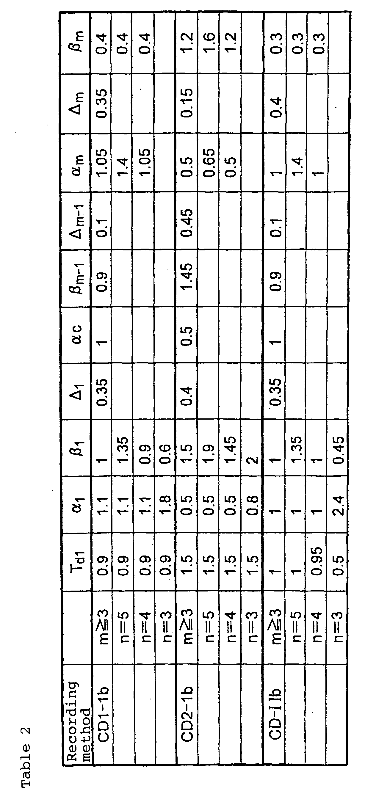
with respect to 5T mark, Td1' =1, α1'=1, β1'=1.35, α 2'=1.45 and βm'=0.3.
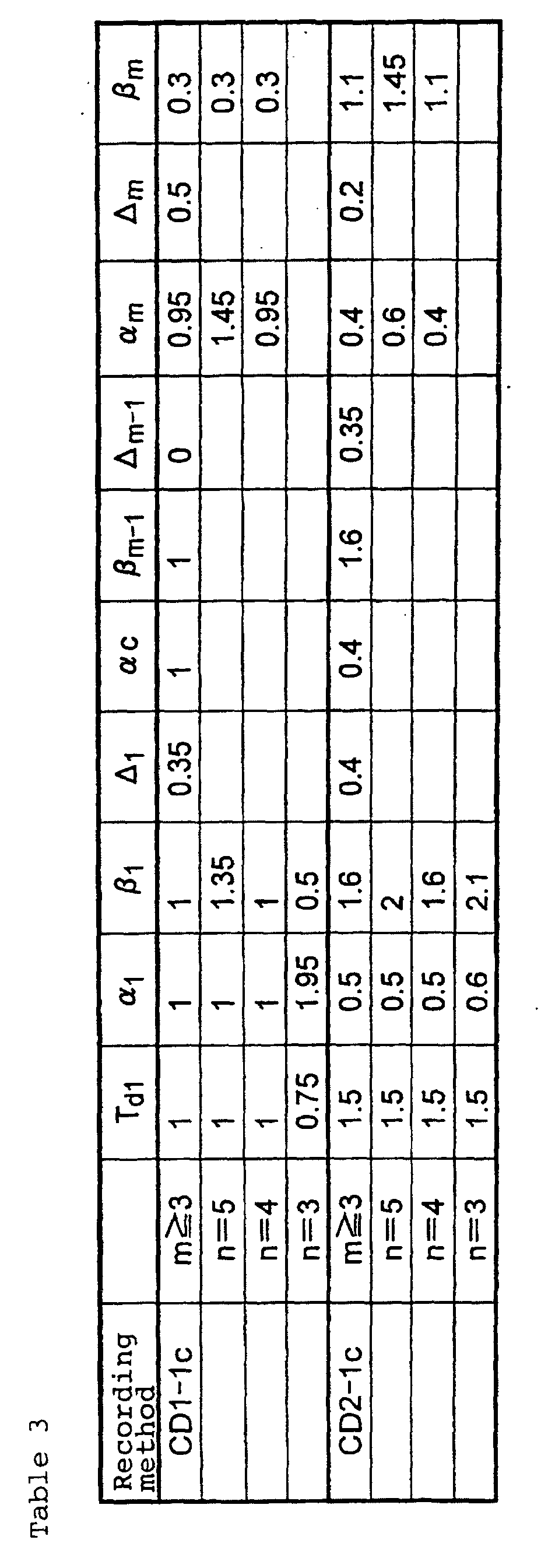
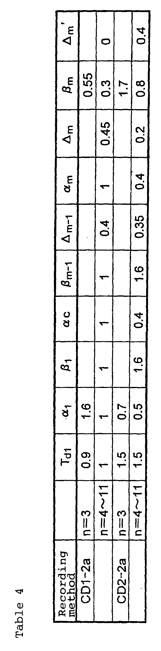

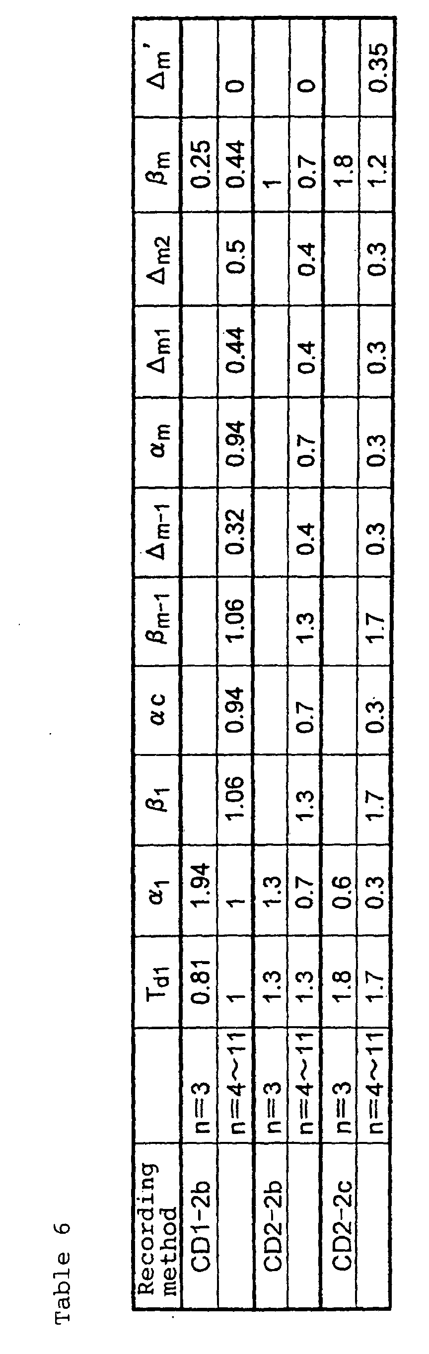
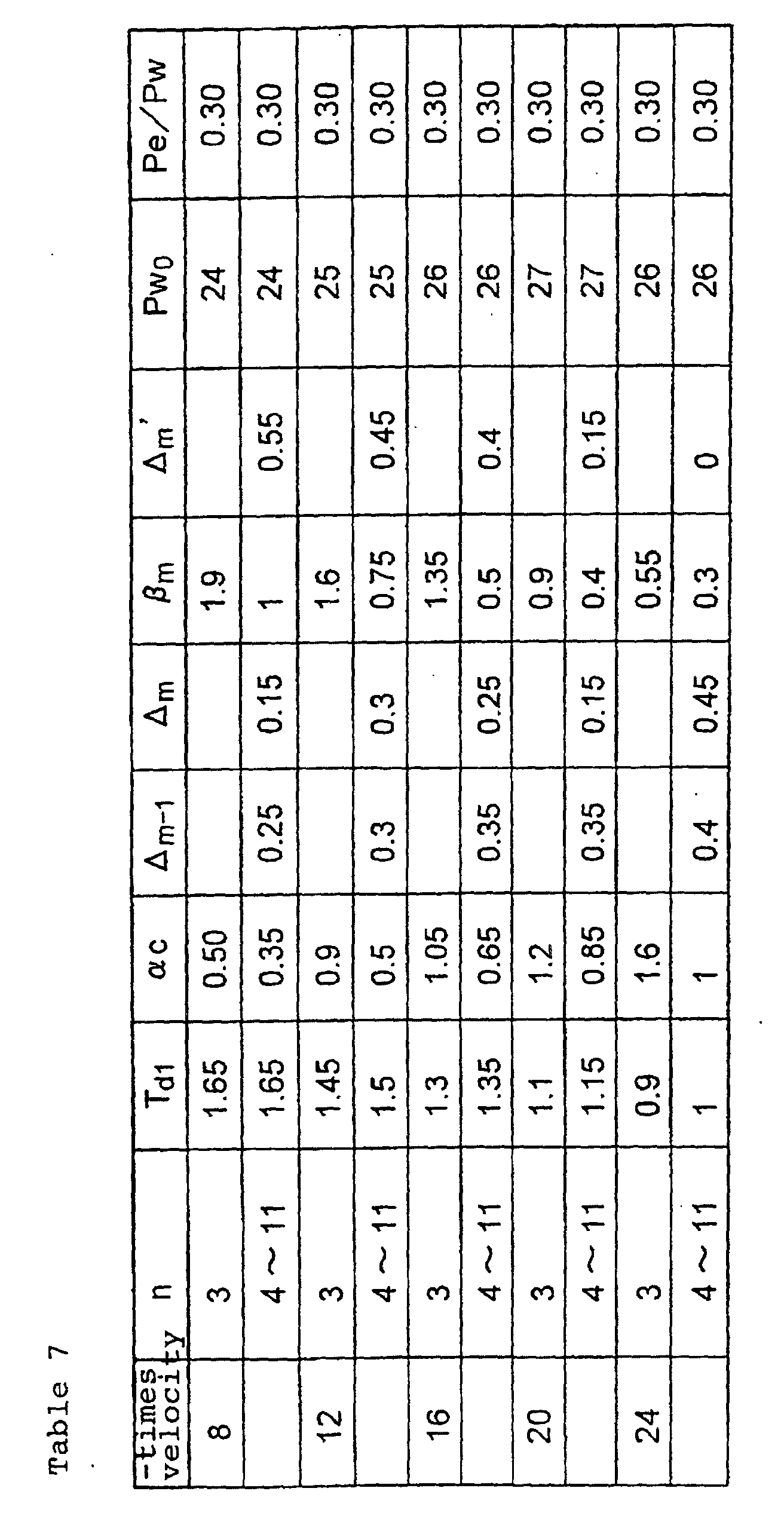
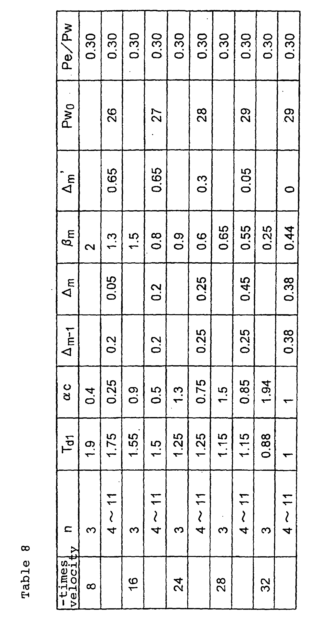
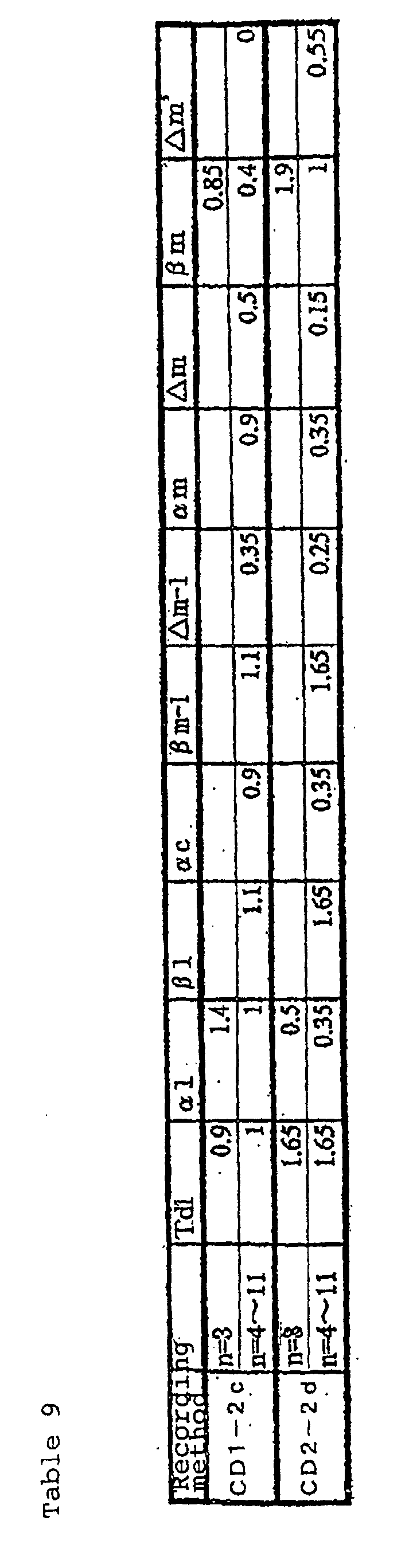
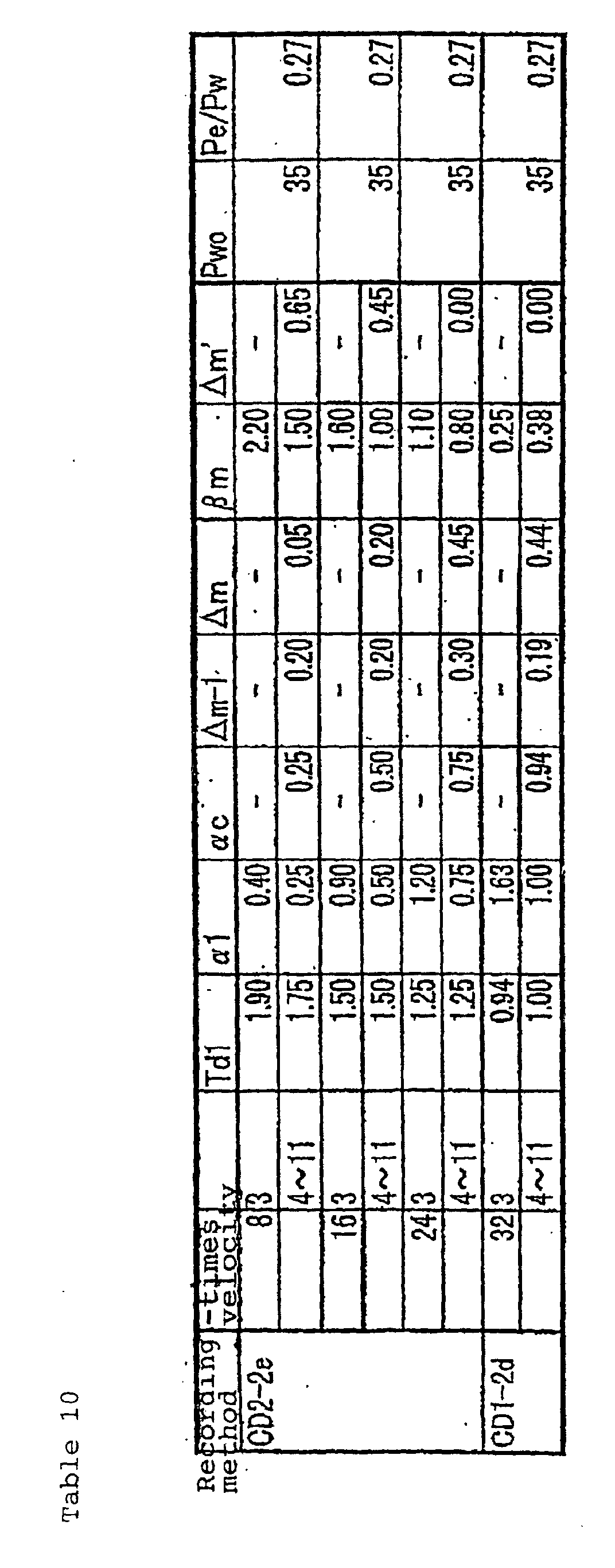

with respect to 5T mark, Td1'=2, α1'=1, β1'=1.45, α 2'=αm'=0.9 and βm'=0.4.
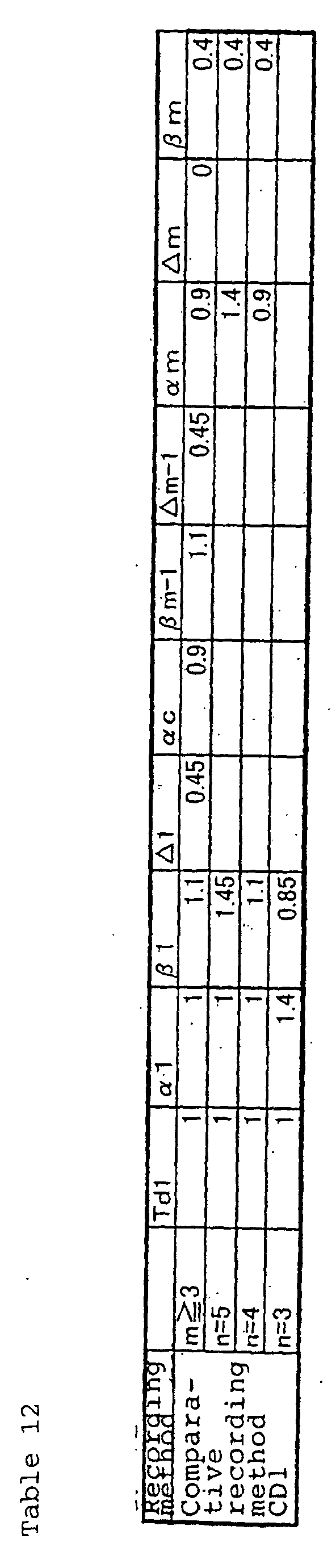

Accordingly, when n=4, β2=βm. When n=5, β1'=βc, α2= αc+ Δm and β2'=βm+Δm' .


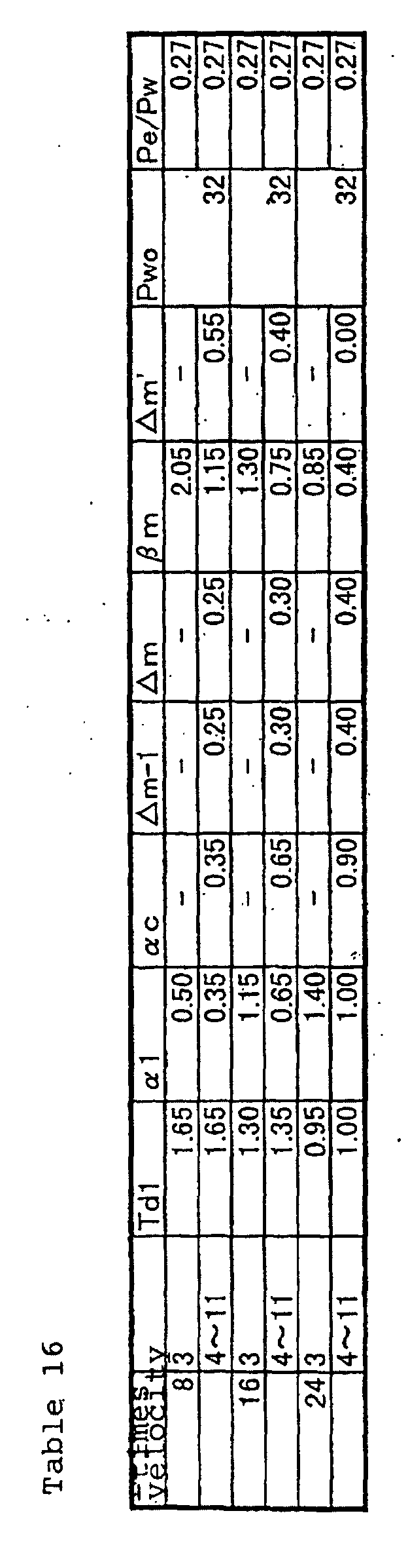


with respect to 5T mark, α1'=1.0, β1'=1.5, α2'=1.0 and β2'=1.1.
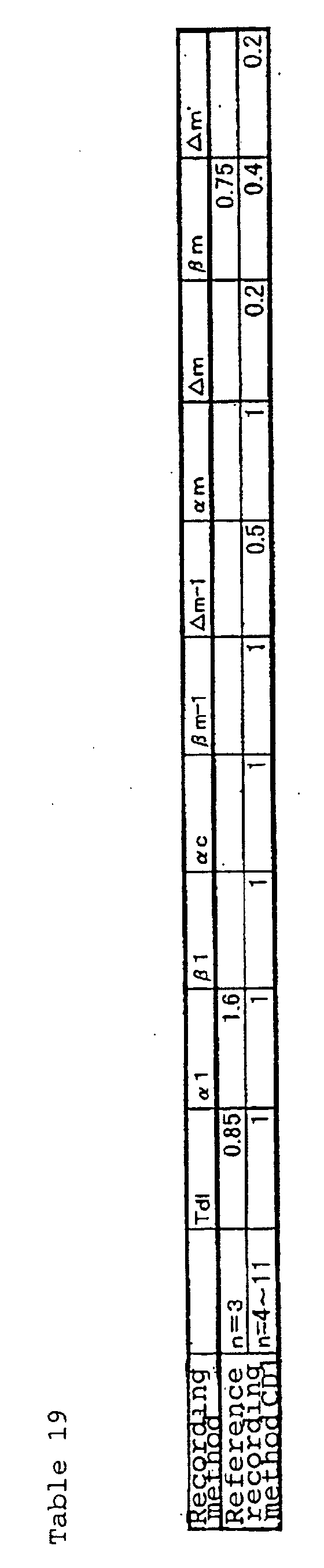

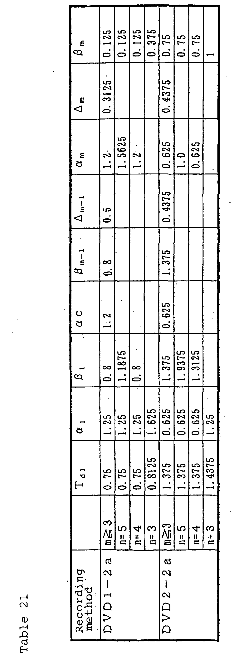
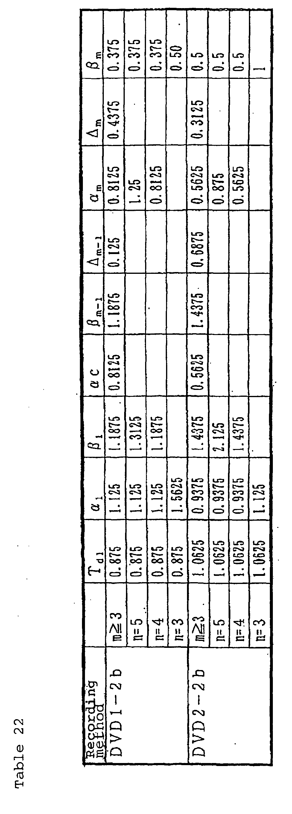
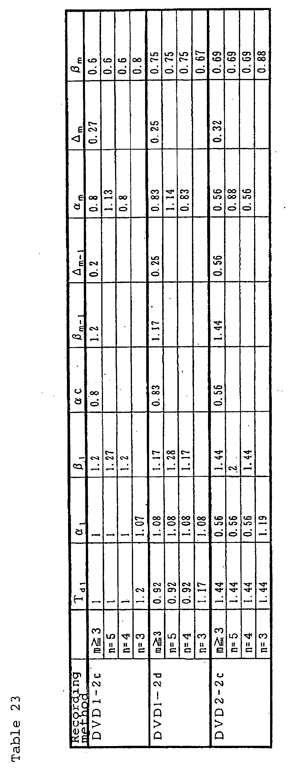
Claims (56)
- A rewritable optical recording medium comprising a substrate having a guide groove formed thereon, and a phase-change type recording layer, wherein a portion in a crystalline state of the phase-change type recording layer corresponds to an unrecorded or erased state, and a portion in an amorphous state of the phase-change type recording layer corresponds to a recorded state, so that an amorphous mark corresponding to the recorded state will be formed upon irradiation with a recording laser beam, and wherein when EFM modulation signals are recorded by overwriting 10 times by one recording method selected from the conditions of the following recording methods CD1-1 and CD1-2 while maintaining the reference clock period T to satisfy VT=V1T1, where V1 is a reference velocity (1-time velocity) which is set to be a linear velocity of 1.2 m/s, V is a linear velocity which is selected to be either V=24V1 i.e. a linear velocity 24 times the reference velocity, or V=32V1 i.e. a linear velocity 32 times the reference velocity, and T1 is 231 nsec, and then, record signals are retrieved at 1-time velocity, the modulation m11 of an eye pattern of the record signals obtained by the retrieving is from 60 to 80%, the top value Rtop of the reflectivity of the eye pattern of the record signals is from 15 to 25%, and jitters of the respective mark lengths and the respective spaces between marks are at most 35 nsec;
Recording method CD1-1:Recording method CD1-2:A laser beam having a wavelength of 780 nm is irradiated via an optical system having a numerical aperture NA of 0.5, wherein when the time length of one amorphous mark is represented by nT (where n is an integer of from 3 to 11),between record marks, an erasing power Pe capable of crystallizing an amorphous phase is applied, andfor a record mark of n=2m (where m is an integer of at least 3), of which the time length (n-j)T (where j is a real number of from -2.0 to 2.0) is divided into m sections of α iT and βiT comprising α 1T, β 1T, α2T, β2T,. . . ., αmT and βmT, so that Σi(αi+βi)=n-j, in the order of α1=0.7 to 1.4, αi=0.7 to 1.2 (where i is an integer of from 2 to m-1, and αi takes a constant value α c between 0.7 to 1.2 irrespective of such i), β1+α 2=1.7 to 2.3, βi-1+ αi=2 (where i is an integer of from 3 to m-1), βm-1+αm=1.7 to 2.3, αm=0.7 to 1.2, and βm=0 to 2, and for a record mark of n=2m+1 (where m is an integer of at least 3), of which the time length (n-k)T (where k is a real number of from -2.0 to 2.0) is divided into m sections of αi'T and βi'T comprising α1'T, β1'T, α2'T, β2'T,. . . ., αm'T and βm'T, so that ∑i(αi'+βi')=n-k, in the order of α1'=α1, β1'=β1+Δ1 (where Δ1=0.3 to 0.6), αi'=αc (where i is an integer of from 2 to m-1), βi-1'+ αi'=2 (where i is an integer of from 3 to m-1), βm-1'=βm- 1+Δm-1 (where Δm-1=0 to 0.6), αm'=αm+Δm (where 0<Δm≦0.6), Δmm= Δm-1+ Δm=0.3 to 0.6, and βm'=βm, a recording laser beam having a constant writing power Pw sufficient to melt the recording layer (provided that Pw is from 20 to 40 mW, and Pe/Pw=0.2 to 0.6) is applied within a time of αiT and αi'T (where i is an integer of from 1 to m), and a recording laser beam having a bias power Pb of less than 1 mW is applied within a time of βiT and βi'T (where i is an integer of from 1 to m); and further,when m is at least 3, α1(=α1'), αc, βm(=βm'), β1, Δ1, βm-1, Δm-1, αm and Δm are constant irrespective of m,when m=2 (n=4, 5), α1, α1', α2, α2', β2 and β2' are made to be equal to α1, α1', α3, α3', β3 and β3' in the case where m is 3, respectively, β1 is made to be equal to either β1 or β2 in the case where m is 3, and β1' is made to be equal to either β1' or β2' in the case where m is 3, andwhen m=1 (n=3), irradiation with a recording laser beam comprising a pair of a writing power irradiation section α1'T and a bias power irradiation section β1'T is carried out;A laser beam having a wavelength of 780 nm is irradiated via an optical system having a numerical aperture NA of 0.5, wherein when the time length of one amorphous mark is represented by nT (where n is an integer of from 3 to 11),between record marks, an erasing power Pe capable of crystallizing an amorphous phase is applied, andfor a record mark of n=2m (where m is an integer of at least 3), of which the time length (n-j)T (where j is a real number of from -2.0 to 2.0) is divided into m sections of α iT and βiT comprising αiT, β1T, α 2T, β2T,. . . ., αmT and βmT, so that ∑i(αi+βi)=n-j, in the order of α1=0.7 to 1.4, αi=0.7 to 1.2 (where i is an integer of from 2 to m-1, and αi takes a constant value αc between 0.7 to 1.2 irrespective of such i), β1+α 2=1.7 to 2.3, βi-1+αi=2 (where i is an integer of from 3 to m-1), βm-1+αm=1.7 to 2.3, αm=0.7 to 1.2, and βm=0 to 2, and for a record mark of n=2m+1 (where m is an integer of at least 3), of which the time length (n-k)T (where k is a real number of from -2.0 to 2.0) is divided into m sections of αi 'T and βi 'T comprising α1'T, β1'T, α2'T, β2'T,. . . ., αm'T and βm'T, so that ∑i(αi'+βi')=n-k, in the order of α1'=α1, β1'=β1, αi'=αc (where i is an integer of from 2 to m-1), βi-1'+αi'=2 (where i is an integer of from 3 to m-1), β m-1'=β m-1+Δm-1 (where Δm-1=0 to 0.6), αm'=αm+Δm, (where 0<Δm≦0.6), Δmm=Δm-1+Δm=0.5 to 1.2, and βm'= βm, a recording laser beam having a constant writing power Pw sufficient to melt the recording layer (provided that Pw is from 20 to 40 mW, and Pe/Pw=0.2 to 0.6) is applied within a time of αiT and αi'T (where i is an integer of from 1 to m), and a recording laser beam having a bias power Pb of less than 1 mW is applied within a time of βiT and β i'T (where i is an integer of from 1 to m); and further,when m is at least 3, α1(=α1'), (β1(=β1'), αc, βm-1, Δm-1, αm, βm and Δm' are constant irrespective of m,when m=2 (n=4, 5), α1, α1', β1, β1', α2, α2' β2 and β2' are made to be equal to α1, α1', β2, β2', α3, α3', β3 and β3' in the case where m is 3, respectively, andwhen m=1 (n=3), irradiation with a recording laser beam comprising a pair of a writing power irradiation section α1'T and a bias power irradiation section β1'T is carried out. - The rewritable optical recording medium according to Claim 1, wherein in the recording at a linear velocity of 24-times velocity (24V1) or 32-times velocity (32V1), when a simple periodic signal comprising a 3T mark (a mark having a time length of 3T, where T is the data reference clock period) and a 3T space (a space between marks, having a time length of 3T), is recorded, and then, a simple periodic signal comprising a 11T mark (a mark having a time length of 11T) and a 11T space (a space between marks, having a time length of 11T), is overwritten, the erase ratio of the 3T mark is at least 20 dB.
- The rewritable optical recording medium according to Claim 1 or 2, wherein when signals are recorded by overwriting 10 times by one recording method selected from the conditions of the following recording methods CD2-1 and CD2-2, at a linear velocity of at least one selected from 8-times velocity (8V1), 10-times velocity (10V1), 12-times velocity (12V1), 16-times velocity (16V1) and 20-times velocity (20V1), of a reference velocity (1-time velocity) V1 which is set to be a linear velocity of 1.2 m/s, and then, record signals are retrieved at 1-time velocity, the modulation m11 of an eye pattern of the record signals obtained by the retrieving is from 60 to 80%, the top value Rtop of the reflectivity of the eye pattern of the record signals is from 15 to 25%, and jitters of the respective mark lengths and the respective spaces between marks are at most 35 nsec;
Recording method CD2-1:Recording method CD2-2:A laser beam having a wavelength of 780 nm is irradiated via an optical system having a numerical aperture NA of 0.5, wherein when the time length of one amorphous mark is represented by nT (where n is an integer of from 3 to 11),between record marks, an erasing power Pe capable of crystallizing an amorphous phase is applied, andfor a record mark of n=2m (where m is an integer of at least 3), of which the time length (n-j)T (where j is a real number of from -2.0 to 2.0) is divided into m sections of αiT and βiT comprising α 1T, β1T, α2T, β2T,...., αmT and βmT, so that ∑i(αi+βi)=n-j, in the order of α1=0.1 to 1, αi=0.1 to 1 (where i is an integer of from 2 to m-1, and αi takes a constant value αc between 0.1 to 1 irrespective of such i), β1+α 2=1.7 to 2.3, βi-1+αi=2 (where i is an integer of from 3 to m-1), βm-1+αm=1.7 to 2.3, αm=0.1 to 1, and βm=0 to 2, and for a record mark of n=2m+1 (where m is an integer of at least 3), of which the time length (n-k)T (where k is a real number of from -2.0 to 2.0) is divided into m sections of αi'T and βi'T comprising α1'T, β1'T, α2'T, β2'T,. . . ., αm'T and βm'T, so that ∑i(αi'+βi')=n-k, in the order of α1'=α1, β1' = β1+ Δ1 (where Δ1=0.3 to 0.6), αi'=αc (where i is an integer of from 2 to m-1), βi-1'+ αi'=2 (where i is an integer of from 3 to m-1), βm-1'=βm- 1+Δm-1 (where Δm-1=0 to 0.6), αm'=αm+Δm (where 0<Δm≦0.6), Δmm=Δm-1+Δm=0.3 to 0.6, and βm' = βm, a recording laser beam having a constant writing power Pw sufficient to melt the recording layer (provided that Pw is from 20 to 40 mW, and Pe/Pw=0.2 to 0.6) is applied within a time of αiT and αi'T (where i is an integer of from 1 to m), and a recording laser beam having a bias power Pb of less than 1 mW is applied within a time of βiT and βi'T (where i is an integer of from 1 to m); and further,when m is at least 3, α1(=α1'), αc, βm(=βm'), β1, Δ1, βm-1, Δm-1, αm and Δm are constant irrespective of m,when m=2 (n=4, 5), α1, α1', α2, α2', β2 and β2' are made to be equal to α1, α1', α3, α3', β3 and β3' in the case where m is 3, respectively, β1 is made to be equal to either β1 or β2 in the case where m is 3, and β1' is made to be equal to either β1' or β2' in the case where m is 3, provided that with respect to β2', the value may further be changed within a range of ±0.5, andwhen m=1 (n=3), irradiation with a recording laser beam comprising a pair of a writing power irradiation section α1'T and a bias power irradiation section β1' T is carried out;A laser beam having a wavelength of 780 nm is irradiated via an optical system having a numerical aperture NA of 0.5, wherein when the time length of one amorphous mark is represented by nT (where n is an integer of from 3 to 11),between record marks, an erasing power Pe capable of crystallizing an amorphous phase is applied, andfor a record mark of n=2m (where m is an integer of at least 3), of which the time length (n-j)T (where j is a real number of from -2.0 to 2.0) is divided into m sections of αiT and βiT comprising α1T, β1T, α2T, β 2T,. . . ., αmT and βmT, so that Σi(αi+βi)=n-j, in the order of α1=0.1 to 1, αi=0.1 to 1 (where i is an integer of from 2 to m-1, and αi takes a constant value αc between 0.1 to 1 irrespective of such i), β1+α2=1.7 to 2.3, βi-1+αi=2 (where i is an integer of from 3 to m-1), βm-1+αm=1.7 to 2.3, αm=0 .1 to 1, and βm=0 to 2, and for a record mark of n=2m+1 (where m is an integer of at least 3), of which the time length (n-k)T (where k is a real number of from -2.0 to 2.0) is divided into m sections of αi' T and βi'T comprising α1'T, β1'T, α2'T, β2'T,. . . ., αm'T and βm'T, so that ∑i(αi'+βi')=n-k, in the order of α 1'=α1, β1'=β1, α i'=αc (where i is an integer of from 2 to m-1), βi-1' + αi=2 (where i is an integer of from 3 to m-1), βm-1'=βm-1+Δm-1 (where Δm-1=0 to 0.6), αm'=αm+Δm (where 0<Δm≦0.6), Δmm=Δm-1+Δm=0.5 to 1.2, and βm' =βm+Δm' (where Δm' =0 to 1), a recording laser beam having a constant writing power Pw sufficient to melt the recording layer (provided that Pw is from 20 to 40 mW, and Pe/Pw=0.2 to 0.6) is applied within a time of αiT and αi'T (where i is an integer of from 1 to m), and a recording laser beam having a bias power Pb of less than 1 mW is applied within a time of βiT and βi' T(where i is an integer of from 1 to m); and further,when m is at least 3, α1(=α1'), β1(=β1'), αc, βm-1, Δm-1, αm, βm and Δm' are constant irrespective of m,when m=2 (n=4, 5), α1, α1', β1, β1', α2, α2', β2 and β2' are made to be equal to α 1, α1', β2, β2', α3, α3', β3 and β3' in the case where m is 3, respectively, andwhen m=1 (n=3), irradiation with a recording laser beam comprising a pair of a writing power irradiation section α1' T and a bias power irradiation section β1' T is carried out. - The rewritable optical recording medium according to any one of Claims 1 to 3, which comprises a substrate having a guide groove formed thereon, and a phase-change type recording layer, wherein a portion in a crystalline state of the phase-change type recording layer corresponds to an unrecorded or erased state, and a portion in an amorphous state of the phase-change type recording layer corresponds to a recorded state, so that an amorphous mark corresponding to the recorded state will be formed upon irradiation with a recording laser beam, and wherein when EFM modulation signals are recorded by overwriting 10 times by one recording methods selected from the conditions of the above-mentioned recording methods CD2-1 and CD2-2 while maintaining the reference clock period T to satisfy VT=V1T1 (where V1 is a reference velocity (1-time velocity) which is set to be a linear velocity of 1.2 m/s, T1 is 231 nsec, and V is any one of 8V1, 10V1, 12V1, 16V1, 20V1, 24V1 and 32V1) at any linear velocity of at least Vmin and less than Vmax, where Vmin is a linear velocity of any one selected from 8-times velocity (8V1), 10-times velocity (10V1), 12-times velocity (12V1), 16-times velocity (16V1) and 20-times velocity (20V1), and Vmax is a linear velocity of either 24-times velocity (24V1) or 32-times velocity (32V1), and then, record signals are retrieved at 1-time velocity, the modulation m11 of an eye pattern of the record signals obtained by the retrieving is from 60 to 80%, the top value Rtop of the reflectivity of the eye pattern of the record signals is from 15 to 25%, and jitters of the respective mark lengths and the respective spaces between marks are at most 35 nsec.
- The rewritable optical recording medium according to any one of Claims 1 to 4, wherein the guide groove has a groove-wobbling signal having a carrier frequency of about 22.05 kHz as calculated as 1-time velocity and frequency-modulated by ±1 kHz by ATIP information, and said ATIP information includes at least one of optimum writing power Pwo, optimum erasing power Peo, optimum bias power Pbo and pulse-division information suitable for the recording linear velocity.
- A rewritable optical recording medium comprising a substrate having a guide groove formed thereon, and a phase-change type recording layer, wherein a portion in a crystalline state of the phase-change type recording layer corresponds to an unrecorded or erased state, and a portion in an amorphous state of the phase-change type recording layer corresponds to a recorded state, so that an amorphous mark corresponding to the recorded state will be formed upon irradiation with a recording laser beam, and wherein when EFM+ modulation signals are recorded by overwriting 10 times by one recording method selected from the conditions of the following recording methods DVD1-1 and DVD1-2 while maintaining the reference clock period T to satisfy VT=V1T1, where V1 is a reference velocity (1-time velocity) which is set to be a linear velocity of 3.49 m/s, V is a linear velocity which is selected to be one of V=6V1 i.e. a linear velocity 6 times the reference velocity, V=8V1 i.e. a linear velocity 8 times the reference velocity, V=10V1 i.e. a linear velocity 10 times the reference velocity and V=12V1 i.e. a linear velocity 12 times the reference velocity, and T1 is 38.2 nsec, and then, record signals are retrieved at 1-time velocity, the modulation m14 of an eye pattern of the record signals obtained by the retrieving is from 55 to 80%, the top value Rtop of the reflectivity of the eye pattern of the record signals is from 18 to 30%, and the clock jitter of the retrieved signals is at most 15%;
Recording method DVD1-1:Recording method DVD1-2:A laser beam having a wavelength of 650 nm is irradiated via an optical system having numerical aperture NA of 0.65, wherein when the time length of one amorphous mark is represented by nT (where n is an integer of from 3 to 11 and 14),between record marks, an erasing power Pe capable of crystallizing an amorphous phase is applied, andfor a record mark of n=2m (where m is an integer of at least 3), of which the time length (n-j)T (where j is a real number of from -2.0 to 2.0) is divided into m sections of αiT and βiT comprising α 1T, β1T, α2T, β2T,. . . ., αmT and β mT, so that Σi(αi+βi)=n-j, in the order of α1=0.7 to 1.4, αi=0.7 to 1.2 (where i is an integer of from 2 to m-1, and αi takes a constant value αc between 0.7 to 1.2 irrespective of such i), β1+α 2=1.7 to 2.3, βi-1+αi=2 (where i is an integer of from 3 to m-1), βm-1+αm=1.7 to 2.3, αm=0.7 to 1.2, and β m=0 to 2, and for a record mark of n=2m+1 (where m is an integer of at least 3), of which the time length (n-k)T (where k is a real number of from -2.0 to 2.0) is divided into m sections of αi'T and βi' T comprising α1'T, β1'T, α2'T, β2'T,. . . ., αm'T and βm'T, so that ∑i(αi'+βi')=n-k, in the order of α1'=α1, β1'=β1+Δ1 (where Δ1=0.3 to 0.6), αi'=αc (where i is an integer of from 2 to m-1), βi-1'+ αi'=2 (where i is an integer of from 3 to m-2), βm-1'=βm- 1+Δm-1 (where Δm-1=0 to 0.6), αm'=αm+Δm (where 0<Δm≦<0.6), Δmm=Δm-1+Δm=0.3 to 0.6, and βm' = βm, a recording laser beam having a constant writing power Pw sufficient to melt the recording layer (provided that Pw is from 10 to 40 mW, and Pe/Pw=0.2 to 0.6) is applied within a time of α iT and αi'T (where i is an integer of from 1 to m), and a recording laser beam having a bias power Pb of less than 1 mW is applied within a time of βiT and βi'T (where i is an integer of from 1 to m); and further,when m is at least 3, α1(=α1'), αc, βm(=βm'), β1, Δ1, βm-1, Δm-1, αm and Δm are constant irrespective of m,when m=2 (n=4, 5), α1, α1', α2, α2', β2 and β2' are made to be equal to α 1, α1', α3, α3', β3 and β3' in the case where m is 3, respectively, β 1 is made to be equal to either β1 or β2 in the case where m is 3, and β1' is made to be equal to either β1' or β2' in the case where m is 3, andwhen m=1 (n=3), irradiation with a recording laser beam comprising a pair of a writing power irradiation section α1'T and a bias power irradiation section β1'T is carried out;A laser beam having a wavelength of 650 nm is irradiated via an optical system having a numerical aperture NA of 0.65, wherein when the time length of one amorphous mark is represented by nT (where n is an integer of from 3 to 11 and 14),between record marks, an erasing power Pe capable of crystallizing an amorphous phase is applied, andfor a record mark of n=2m (where m is an integer of at least 3), of which the time length (n-j)T (where j is a real number of from -2.0 to 2.0) is divided into m sections of αiT and βiT comprising α 1T, β1T, α2T, β2T,. . . ., αmT and βmT, so that Σi(αi+βi)=n-j, in the order of α1=0.7 to 1.4, αi=0.7 to 1.2 (where i is an integer of from 2 to m-1, and αi takes a constant value αc between 0.7 to 1.4 irrespective of such i), β1+ α2=1.7 to 2.3, βi-1+αi=2 (where i is an integer of from 3 to m-1), βm-1+αm=1.7 to 2.3, αm=0.7 to 1.2, and βm=0 to 2, and for a record mark of n=2m+1 (where m is an integer of at least 3), of which the time length (n-k)T (where k is a real number of from -2.0 to 2.0) is divided into m sections of αi'T and βi' T comprising α1'T, β1'T, α2'T, β2'T,...., αm'T and βm'T, so that ∑i(αi'+βi')=n-k, in the order of α1'=α1, β1'=β1, αi'=αc (where i is an integer of from 2 to m-1), βi-1'+αi'=2 (where i is an integer of from 3 to m-1), βm-1'=βm-1+ Δm-1 (where Δm-1=0 to 0.6), αm'=αm+Δm (where 0<Δm≦0.6), Δmm=Δm-1+Δm=0.5 to 1.2, and βm'=βm, a recording laser beam having a constant writing power Pw sufficient to melt the recording layer (provided that Pw is from 10 to 40 mW, and Pe/Pw=0.2 to 0.6) is applied within a time of αiT and αi'T (where i is an integer of from 1 to m), and a recording laser beam having a bias power Pb of less than 1 mW is applied within a time of βiT and βi'T (where i is an integer of from 1 to m); and further,when m is at least 3, α1(=α1'), β1(=β1'), αc, βm-1, Δm-1, αm, βm and Δm' are constant irrespective of m,when m=2 (n=4, 5), α1, α1', β1, β1', α2, α2', β2 and β2' are made to be equal to α 1, α1', β2, β 2', α3, α3', β3 and β3' in the case where m is 3, respectively, andwhen m=1 (n=3), irradiation with a recording laser beam comprising a pair of a writing power irradiation section α1'T and a bias power irradiation section β1'T is carried out. - The rewritable optical recording medium according to Claim 6, wherein in the recording at a linear velocity of one of 6-times velocity (6V1), 8-times velocity (8V1), 10-times velocity (10V1), and 12-times velocity (12V1), when a simple periodic signal comprising a 3T mark (a mark having a time length of 3T, where T is the data reference clock period) and a 3T space (a space between marks, having a time length of 3T), is recorded, and then, a simple periodic signal comprising a 14T mark (a mark having a time length of 14T) and a 14T space (a space between marks, having a time length of 14T), is overwritten, the erase ratio of the 3T mark is at least 20 dB.
- The rewritable optical recording medium according to Claim 6 or 7, wherein when signals are recorded by overwriting 10 times by one recording method selected from the conditions of the following recording methods DVD2-1 and DVD2-2, at a linear velocity of at least one selected from 2-times velocity (2V1), 2.5-times velocity (2.5V1), 3-times velocity (3V1), 4-times velocity (4V1) and 5-times velocity (5V1), of a reference velocity (1-time velocity) V1 which is set to be a linear velocity of 3.49 m/s, and then, record signals are retrieved at 1-time velocity, the modulation m14 of an eye pattern of the record signals obtained by the retrieving is from 55 to 80%, the top value Rtop of the reflectivity of the eye pattern of the record signals is from 18 to 30%, and the clock jitter of the retrieved signals is at most 15%; Recording method DVD2-1:Recording method DVD2-2:A laser beam having a wavelength of 650 nm is irradiated via an optical system having a numerical aperture NA of 0.65, wherein when the time length of one amorphous mark is represented by nT (where n is an integer of from 3 to 11 and 14),between record marks, an erasing power Pe capable of crystallizing an amorphous phase is applied, andfor a record mark of n=2m (where m is an integer of at least 3), of which the time length (n-j)T (where j is a real number of from -2.0 to 2.0) is divided into m sections of α iT and βiT comprising α1T, β1T, α 2T, β2T,. . . ., α mT and βmT, so that Σi(αi+βi)=n-j, in the order of α1=0.1 to 1, αi=0.1 to 1 (where i is an integer of from 2 to m-1, and αi takes a constant value αc between 0.1 to 1 irrespective of such i), β1+ α2=1.7 to 2.3, βi-1+αi=2 (where i is an integer of from 3 to m-1), βm-1+αm=1.7 to 2.3, αm=0.1 to 1, and βm=0 to 2, and for a record mark of n=2m+1 (where m is an integer of at least 3), of which the time length (n-k)T (where k is a real number of from -2.0 to 2.0) is divided into m sections of αi'T and βi'T comprising α1'T, β1'T, α2'T, β2'T,. . . ., αm'T and βm'T, so that ∑i(αi'+βi')=n-k, in the order of α1'=α1, β1'=β1+Δ1 (where Δ1=0.3 to 0.6), αi'=αc (where i is an integer of from 2 to m-1), βi-1'+ α i'=2 (where i is an integer of from 3 to m-1), β m-1'=βm- 1+Δm-1 (where Δm-1=0 to 0.6), αm'=αm+Δm (where 0<Δm≦0.6), Δmm=Δm-1+Δm=0.3 to 0.6, and βm'=βm, a recording laser beam having a constant writing power Pw sufficient to melt the recording layer (provided that Pw is from 10 to 40 mW, and Pe/Pw=0.2 to 0.6) is applied within a time of αiT and αi' T (where i is an integer of from 1 to m), and a recording laser beam having a bias power Pb of less than 1 mW is applied within a time of βiT and βi' T (where i is an integer of from 1 to m); and further,when m is at least 3, α1(=α1'), αc, βm(=βm'), β1, Δ1, β m-1, Δm-1, αm and Δm are constant irrespective of m,when m=2 (n=4, 5), α1, α1', α2, α2', β2 and β2' are made to be equal to α 1 , α1', α3, α3', β3 and β3' in the case where m is 3, respectively, β1 is made to be equal to either β1 or β2 in the case where m is 3, and β1' is made to be equal to either β1' or β2' in the case where m is 3, provided that with respect to β2', the value may further be changed within a range of ±0.5, andwhen m=1 (n=3), irradiation with a recording laser beam comprising a pair of a writing power irradiation section α1'T and a bias power irradiation section β1'T is carried out;A laser beam having a wavelength of 650 nm is irradiated via an optical system having a numerical aperture NA of 0.65, wherein when the time length of one amorphous mark is represented by nT (where n is an integer of from 3 to 11 and 14),between record marks, an erasing power Pe capable of crystallizing an amorphous phase is applied, andfor a record mark of n=2m (where m is an integer of at least 3), of which the time length (n-j)T (where j is a real number of from -2.0 to 2.0) is divided into m sections of αiT and βiT comprising α1T, β1T, α2T, β2T,. . . ., αmT and βmT, so that Σi(αi+βi)=n-j, in the order of α1=0.1 to 1, αi=0.1 to 1 (where i is an integer of from 2 to m-1, and αi takes a constant value αc between 0.1 to 1 irrespective of such i), β1+α2=1.7 to 2.3, βi-1+ αi=2 (where i is an integer of from 3 to m-1), βm-1+αm=1.7 to 2.3, α m=0.1 to 1, and βm=0 to 2, and for a record mark of n=2m+1 (where m is an integer of at least 3), of which the time length (n-k)T (where k is a real number of from -2.0 to 2.0) is divided into m sections of αi'T and βi'T comprising α1' T, β1'T, α2'T, β2'T,. . . ., αm'T and βm'T, so that ∑i(αi'+βi')=n-k, in the order of α1' =α1, β1' = β1, αi'=αc (where i is an integer of from 2 to m-1), βi-1' + αi=2 (where i is an integer of from 3 to m-1), βm-1'=βm-1+Δm-1 (where Δm-1=0 to 0.6), αm'=αm+Δm (where 0<Δm≦0.6), Δmm=Δm-1+Δm=0.5 to 1.2, and βm'=βm+Δm' (where Δm'=0 to 1), a recording laser beam having a constant writing power Pw sufficient to melt the recording layer (provided that Pw is from 10 to 40 mW, and Pe/Pw=0.2 to 0.6) is applied within a time of αiT and αi' T (where i is an integer of from 1 to m), and a recording laser beam having a bias power Pb of less than 1 mW is applied within a time of βiT and βi' T(where i is an integer of from 1 to m); and further,when m is at least 3, α1(=α1'), β1(=β1'), αc, βm-1, Δm-1, αm, βm and Δm' are constant irrespective of m,when m=2 (n=4, 5), α1, α1', β1, β1', α 2, α 2', β 2 and β2' are made to be equal to α1, α1', β2, β2', α3, α3', β3 and β3' in the case where m is 3, respectively, andwhen m=1 (n=3), irradiation with a recording laser beam comprising a pair of a writing power irradiation section α1'T and a bias power irradiation section β1'T is carried out.
- The rewritable optical recording medium according to any one of Claims 6 to 8, which comprises a substrate having a guide groove formed thereon, and a phase-change type recording layer, wherein a portion in a crystalline state of the phase-change type recording layer corresponds to an unrecorded or erased state, and a portion in an amorphous state of the phase-change type recording layer corresponds to a recorded state, so that an amorphous mark corresponding to the recorded state will be formed upon irradiation with a recording laser beam, and wherein when EFM+ modulation signals are recorded by overwriting 10 times by one recording method selected from the conditions of the above-mentioned recording methods DVD2-1 and DVD2-2 while maintaining the reference clock period T to satisfy VT=V1T1 (where V1 is a reference velocity (1-time velocity) which is set to be a linear velocity of 3.49 m/s, T1 is 38.2 nsec, and V is any one of 2V1, 2.5V1, 3V1, 4V1, 5V1, 6V1, 8V1, 10V1 and 12V1) at any linear velocity of at least Vmin and less than Vmax, where Vmin is a linear velocity of any one selected from 2-times velocity (2V1), 2.5-times velocity (2.5V1), 3-times velocity (3V1), 4-times velocity (4V1) and 5-times velocity (5V1), and Vmax is a linear velocity of any one selected from 6-times velocity (6V1), 8-times velocity (8V1), 10-times velocity (10V1) and 12-times velocity (12V1), and then, record signals are retrieved at 1-time velocity, the modulation m14 of an eye pattern of the record signals obtained by the retrieving is from 55 to 80%, the top value Rtop of the reflectivity of the eye pattern of the record signals is from 18 to 30%, and the clock jitter of the retrieved signals is at most 15%.
- The rewritable optical recording medium according to any one of Claims 6 to 9, wherein the guide groove has a groove-wobbling signal having a period 32 times the reference clock period T and phase-modulated by ATIP information, and said ATIP information is written beforehand on the substrate to include at least one of optimum writing power Pwo, optimum erasing power Peo, optimum bias power Pbo and pulse-division information suitable for the recording linear velocity.
- The rewritable optical recording medium according to any one of Claims 6 to 9, wherein the guide groove has a groove-wobbling signal for wobbling in a period 156 times the reference clock period T, and at least one of optimum writing power Pwo, optimum erasing power Peo, optimum bias power Pbo and pulse-division information suitable for the recording linear velocity, is written on the substrate beforehand.
- The rewritable optical recording medium according to any one of Claims 6 to 11, wherein the phase-change type recording layer has a composition containing Sb as the main component.
- The rewritable optical recording medium according to Claim 12, wherein the phase-change type recording layer further contains Ge and/or Te, and in the phase-change type recording layer, the content of Ge is from 1 atomic% to 30 atomic%, and the content of Te is from 0 atomic% to 30 atomic%.
- The rewritable optical recording medium according to Claim 12 or 13, wherein the phase-change type recording layer contains at least 10 atomic% of Te, and in the phase-change type recording layer, Sb/Te is at least 4.5, and the atomic ratio of Ge to Te is from 1:3 to 1:20.
- The rewritable optical recording medium according to Claim 14, wherein the phase-change type recording layer is made of an alloy having, as the main component, a composition represented by Gey(SbxTe1-x)1-y (where 0.01 ≦y≦ 0.06 and 0.82≦x≦0.9).
- The rewritable optical recording medium according to Claim 15, wherein the phase-change type recording layer is made of an alloy having, as the main component, a composition represented by MzGey(SbxTe1-x)1-y-z (where 0.01 ≦ z≦0.1, 0.01≦y≦0.06 and 0.82≦x≦0.9, and M represents at least one element selected from the group consisting of Ga and In).
- The rewritable optical recording medium according to Claim 15 or 16, wherein the Sb/Te ratio is within a range of from 5.5 to 7.3.
- The rewritable optical recording medium according to any one of Claims 15 to 17, wherein when the rewritable optical recording medium is subjected to initial crystallization by means of a laser beam, the initial crystallization is carried out by irradiating the laser beam so that the linear velocity of the optical recording medium to the laser beam would be from 0.1 m/s to 3 m/s.
- The rewritable optical recording medium according to Claim 12 or 13, wherein in the phase-change type recording layer, the content of Te is less than 10 atomic%, and the content of Ge is from 1 atomic% to 30 atomic%.
- The rewritable optical recording medium according to Claim 19, wherein the phase-change type recording layer is made of an alloy having, as the main component, a composition represented by TeγM1β(GeαSb1-α)1-β-γ (where 0.01≦α≦0.3, 0≦β≦0.3, 0≦γ<0.1, 2≦β/γ and 0<β+γ≦ 0.4, and M1 represents one element selected from the group consisting of In, Ga and Sn).
- The rewritable optical recording medium according to any one of Claims 1 to 20, wherein the thickness of the phase-change type recording layer is from 10 to 30 nm.
- The rewritable optical recording medium according to any one of Claims 1 to 21, wherein the rewritable optical recording medium further has a reflective layer, and the sheet resistivity of the reflective layer is from 0.05Ω/□ to 0.2Ω/□.
- The rewritable optical recording medium according to any one of Claims 1 to 22, wherein each of the modulation m11 and the reflectivity Rtop in the crystalline state maintains at least 90% of its initial value, even after being held in an accelerated test environment at a temperature of 105°C for 3 hours.
- A recording method for a rewritable optical recording medium, to be used for the rewritable optical recording medium as defined in any one of Claims 1 to 23, which comprises recording information by a plurality of record mark lengths and space lengths between record marks, wherein:between record marks, a laser beam having an erasing power Pe capable of crystallizing an amorphous phase is applied to form spaces between record marks, andwhen the time length of one record mark is represented by nT (where T is the reference clock period), for a record mark of n=2m (where m is an integer of at least 1), of which the time length (n-j)T (where j is a real number of from -2.0 to 2.0) is divided into m sections of αiT and βiT comprising α1T, β1T, α2T, β 2T,. . . ., αmT and βmT (provided that Σi(αi+βi)=n-j), and for a record mark of n=2m+1 (where m is an integer of at least 1), of which the time length (n-k)T (where k is a real number of from -2.0 to 2.0) is divided into m sections of αi'T and βi'T comprising α1'T, β1'T, α2'T, β2'T,. . . ., αm'T and βm'T (provided that ∑i(αi'+β i')=n-k), a laser beam having a constant writing power Pw sufficient to melt the recording layer is applied within a time of αiT and αi'T (where i is an integer of from 1 to m), and a laser beam having a bias power Pb is applied within a time of βiT and βi'T (where i is an integer of from 1 to m); and further,when m≧3,for a record mark of n=2m, when the start time for nT mark is represented by T0,(i) after a delay time Td1T from T0, α1T is generated, then,(ii) within i=2 to m, βi-1T and αiT are alternately generated in this order, while βi-1+αi maintains about period 2 (provided that at i=2 and/or i=m, βi-1+α1 may be deviated from about period 2 within a range of ±0.5, and when m≧4, βi-1 and αi take constant values βc and αc, respectively, within i=3 to m-1), and then,(iii) βmT is generated, andfor a record mark of n=2m+1, when the start time for nT mark is represented by T0,(i) after a delay time Td1'T from T0, α1'T is generated, then,(ii) within i=2 to m, βi-1'T and αi'T are alternately generated in this order, while βi-1+αi' maintains about period 2 (provided that at i=2 and/or i=m, βi-1'+αi' may be deviated from about period 2 within a range of ±2, and when m≧4, βi-1' and αi' take constant values β c and αc, respectively, within i=3 to m-1), and then,(iii) βm'T is generated, andwith the same m, for a record mark of n=2m and a record mark of n=2m+1, αm≠ αm', and at least one set selected from (Td1, Td1'), (α1, α1'), (β1, β1'), (βm-1 and βm-1') and (βm and βm') takes different values.
- The recording method according to Claim 24, wherein when m ≧3, with the same m, for a record mark of n=2m and a record mark of n=2m+1, αm ≠ α m' and β1≠β1', and at least one set selected from (Td1, Td1'), (α1, α1'), (βm-1 and βm-1') and (βm and βm') takes different values.
- The recording method according to Claim 25, wherein the relation of αm and αm' is made to be αm'=αm+Δm (where 0<Δm≦1), and the relation of βm and βm' is made to be β1'=β1+Δ1 (where 0<Δ1≦1).
- The recording method according to Claim 25 or 26, wherein when m is at least 3, the relations of Td1'= Td1, α1'=α1, β1+α2=1.5 to 2.5, βm-1+αm=1.5 to 2.5, β1'=β1+Δ1 (where 0<Δ1≦1), βm-1' = βm-1+ Δm-1 (where Δm-1=0 to 1), αm' = αm+Δm (where 0<Δm≦1), Δmm=Δm-1+Δm, 0<Δmm≦1 and βm'=βm+ Δm' (where Δm'=0 to 1), are satisfied, and when m is at least 3, Td1, α1, β1, Δ1, αc, βm-1, Δm-1, αm, Δm, βm and Δm' are constant irrespective of m.
- The recording method according to any one of Claims 25 to 27, wherein when m=2, α1, α1', α2, α2', β2 and β2' are made to be equal to α1, α1', αm, αm', , βm and βm' in the case of any m where m is at least 3, respectively (provided that with respect to β2', the value may further be changed within a range of ±0.5), β1 is made to be equal to either β1 or βm-1 in the case of any m where m is at least 3, and β1' is made to be equal to either β1' or βm-1' in the case of any m where m is at least 3.
- The recording method according to any one of Claims 25 to 28, wherein when m is at least 3, at least one formula is satisfied among Td1+α1=2, α1=αc, β1+α2=2, βm-1+αm=2 and αm=αc.
- The recording method according to Claim 29, wherein also when m=2, at least one formula is satisfied among Td1+α1= Td1'+α1'=2, α1=α1'=αc, β1+α2=2 and α2=αc.
- The recording method according to any one of Claims 24 to 30, wherein the recording linear velocity is set to be a linear velocity of at most 32 times the reference linear velocity V1=1.2 to 1.4 m/s, and EFM modulation information is recorded by a plurality of record mark lengths and space lengths between record marks, wherein the time length of one record mark is set to be nT (where n is an integer of from 3 to 11), the ratio of an erasing power Pe to a writing power Pw is set to be Pe/Pw =0.2 to 0.6, and a bias power Pb is set to be Pb≦0.2Pe.
- The recording method according to any one of Claims 24 to 30, wherein the recording linear velocity is set to be a linear velocity of at most 12 times the reference linear velocity V1=3.49 m/s, and EFM+ modulation information is recorded by a plurality of record mark lengths and space lengths between record marks, wherein the time length of one record mark is set to be nT (where n is an integer of from 3 to 11 and 14), the ratio of an erasing power Pe to a writing power Pw is set to be Pe/Pw =0.2 to 0.6, and a bias power Pb is set to be Pb≦0.2Pe.
- A recording method for a rewritable optical recording medium, which comprises recording information on a rewritable optical recording medium by a plurality of record mark lengths and space lengths between record marks, wherein:between record marks, a laser beam having an erasing power Pe capable of crystallizing an amorphous phase is irradiated to form spaces between record marks, andwhen the time length of one record mark is represented by nT (where T is the reference clock period), for a record mark of n=2m (where m is an integer of at least 1), of which the time length (n-j)T (where j is a real number of from -2.0 to 2.0) is divided into m sections of αiT and βiT comprising α1T, β1T, α2T,β 2T,. . . ., αmT and βmT (provided that ∑i(αi+βi)=n-j), and for a record mark of n=2m+1 (where m is an integer of at least 1), of which the time length (n-k)T (where k is a real number of from -2.0 to 2.0) is divided into m sections of αi'T and βi'T comprising α1'T, β1'T, α 2'T, β2'T,. . . ., αm'T and βm'T (provided that ∑i(αi'+β i')=n-k), a laser beam having a constant writing power Pw sufficient to melt the recording layer is applied within a time of αiT and αi'T (where i is an integer of from 1 to m), and a laser beam having a bias power Pb is applied within a time of βiT and βi'T (where i is an integer of from 1 to m); and further,when m≧3,for a record mark of n=2m, when the start time for nT mark is represented by T0,(i) after a delay time Td1T from T0, α1T is generated, then,(ii) within i=2 to m, βi-1T and αiT are alternately generated in this order, while βi-1+αi maintains about period 2 (provided that at i=2 and/or i=m, βi-1+ α1 may be deviated from about period 2 within a range of ±0.5, and when m≧4, βi-1 and αi take constant values βc and αc, respectively, within i=3 to m-1), and then,(iii) βmT is generated, andfor a record mark of n=2m+1, when the start time for nT mark is represented by T0,(i) after a delay time Td1'T from T0, α1' T is generated, then,(ii) within i=2 to m, βi-1' T and αi'T are alternately generated in this order, while βi-1'+αi' maintains about period 2 (provided that at i=2 and/or i=m, βi-1'+αi' may be deviated from about period 2 within a range of ± 2, and when m≧4, βi-1' and αi' take constant values βc and αc, respectively, within i=3 to m-1), and then,(iii) βm' T is generated, andwith the same m, for a record mark of n=2m and a record mark of n=2m+1, Td1=Td1', α1=α1', β1=β1' and αm≠ αm', and at least one set selected from (βm-1 and βm-1') and (βm and βm') takes different values.
- The recording method according to Claim 33, wherein when m is at least 3, with the same division number m, βm-1'+αm'+βm' in the case where n is an odd number, is larger by from 0.5 to 1.5 than βm-1+αm+βm in the case where n is an even number.
- The recording method according to Claim 33 or 34, wherein when m is at least 3, the relations of Td1' = Td1, α1'=α1, β1+α2=1.5 to 2.5, βm-1+αm=1.5 to 2.5, βm-1'=βm- 1+Δm-1 (where Δm-1=0 to 1), αm'=αm+Δm (where 0<Δm≦1), β m'=βm+Δm' (where Δm'=0 to 1) and Δm-1+Δm+Δm'=0.5 to 1.5 are satisfied, and further, Td1, α1, β1, αc, βm-1, Δm-1, αm, βm and Δm' are constant irrespective of m, and Δm takes either value of Δm1 or Δm2 depending upon m.
- The recording method according to any one of Claims 33 to 35, wherein when m=2, α1, α1', β1, β1, α2, α2', β2 and β2' are made to be equal to α1, α1', βm-1, βm-1', αm, αm', βm and βm' in the case of any m where m is at least 3, respectively.
- The recording method according to any one of Claims 33 to 36, wherein when m is at least 3, Δm=Δm1=Δm2.
- The recording method according to any one of Claims 33 to 37, wherein when m is at least 3, at least one formula is satisfied among Td1+α1=2, α1=αc, β1+α2=2, βm-1+αm=2 and αm=αc.
- The recording method according to Claim 38, wherein also when m=2, at least one formula is satisfied among Td1+α1= Td1'+α1'=2, α1=α1', β1+α2=2 and α2=αc.
- The recording method according to Claim 35, wherein when m is at least 3, with the same division number m, the relations of Td1'= Td1, α1= α1', Td1+α1=2, βm-1'=βm-1+ Δ m-1 (where Δm-1=0 to 1), αm' = αc+ Δm (where 0< Δm≦1), Δm-1+ Δm+Δm'=0.5 to 1.5, βm'=βm+Δm' and Δm'=0 to 1, are satisfied, and α1, αc, Δm-1, Δm, βm and Δm' are constant irrespective of m,
when m=2, α1, α1', β1, β1', α2, α2', β2 and β2' are made to be equal to α1, α1', β2 (=βc), β2' (=βc+Δm-1), α 3 (=αc), α3'(=αc+Δm), β3 and β3' (=β3+Δm') in the case where m is at least 3, respectively. - The recording method according to any one of Claims 33 to 40, wherein α1' where n=3, is larger than α1' where n is at least 4.
- The recording method according to any one of Claims 33 to 41, wherein when Td1' where n=3 and 5 is represented by Td1a and Td1c, respectively, Td1 where n=4 is represented by Td1b, and Td1 and Td1' where n is at least 6 are represented by Td1d, at least one selected from Td1a, Td1b and Td1c takes a value different from Td1d.
- The recording method according to any one of Claims 24 to 42, wherein the rewritable optical recording medium is a circular disk, and recording is carried out at a plurality of recording linear velocities while controlling the recording linear density to be constant so that it will be the same as in a compact disk CLV-recorded at 1-time reference velocity (i.e. 1.2 m/s to 1.4 m/s in the case of CD, and 3.49 m/s in the case of DVD), in the same disk plane, wherein the maximum linear velocity Vmax among the recording linear velocities is 20-times velocity, 24-times velocity or 32-times velocity in the case of CD, and 6-times velocity, 8-times velocity, 10-times velocity or 12-times velocity in the case of DVD; and αi=αimax (where i=1 to m) at the Vmax is from 0.5 to 2, and αi'=αimax' (where i=1 to m) at the Vmax is from 0.5 to 2, and αi and αi' (where i=1 to m) are permitted to simply decrease as the linear velocity lowers.
- The recording method according to Claim 43, wherein when the minimum linear velocity Vmin is 8-times velocity, 10-times velocity, 12-times velocity or 16-times velocity in the case of CD, and 2.5-times velocity, 3-times velocity, 4-times velocity or 5-times velocity in the case of DVD, Td1+α1, Td1'+α1', βi-1+αi=2, and βi-1'+αi'=2 (where i=3 to m-1) are, respectively, constant irrespective of the linear velocity within a linear velocity range of from the Vmin to the Vmax when m is at least 3.
- The recording method according to Claim 43 or 44, wherein at any linear velocity to be used, βm=0 to 2, and βm'=0 to 3, and βm and βm' are permitted to simply increase as the linear velocity lowers.
- The recording method according to any one of Claims 43 to 45, wherein Δm' is permitted to simply increase as the linear velocity lowers.
- The recording method according to any one of Claims 43 to 46, wherein among Td1', α1' and β1' where n=3, Td1' and β1' are permitted to simply increase as the linear velocity lowers, and α1' is permitted to simply decrease as the linear velocity lowers.
- The recording method according to any one of Claims 43 to 47, wherein at any linear velocity to be used, βiT (where i=1 to m) and βi'T (where i=1 to m-1) are at least 2 nsec.
- The recording method according to any one of Claims 43 to 48, wherein when EFM modified information is recorded on the circular disk rewritable optical recording medium by a plurality of mark lengths, the optical recording medium is rotated so that the linear velocity at the outermost periphery of the record area of the optical recording medium, would be at least 20-times velocity, based on the reference linear velocity (1-time velocity) being a linear velocity of from 1.2 m/s to 1.4 m/s.
- The recording method according to Claim 49, wherein the disk is rotated so that the linear velocity at the innermost periphery of the record area would be at least 16-times velocity of the reference linear velocity, and the recording linear velocity becomes higher towards the outer periphery.
- The recording method according to Claim 49 or 50, wherein the record area is divided into a plurality of imaginary zones in every certain radius, and βm=0 to 3, and further, βm is made to simply increase towards the inner peripheral zone, and αi and αi' are made to simply decrease towards the inner peripheral zone.
- The recording method according to any one of Claims 49 to 51, wherein the values of Pb, Pw and Pe/Pw are substantially constant at any radial position.
- The recording method according to any one of Claims 43 to 48, wherein when EFM+ modified information is recorded on the circular disk rewritable optical recording medium by a plurality of mark lengths, the optical recording medium is rotated so that the linear velocity at the outermost periphery of the record region of the optical recording medium, would be at least 6-times velocity, based on the reference linear velocity (1-time velocity) being a linear velocity of 3.49 m/s.
- The recording method according to Claim 53, wherein the disk is rotated so that the linear velocity at the innermost periphery of the record region would be at least 6-times velocity of the reference linear velocity, and the recording linear velocity becomes higher towards the outer periphery.
- The recording method according to Claim 53 or 54, wherein the record region is divided into a plurality of imaginary zones in every certain radius, and βm=0 to 3, and further, βm is made to simply increase towards the inner peripheral zone, and αi and αi' are made to simply decrease towards the inner peripheral zone.
- The recording method according to any one of Claims 53 to 55, wherein the values of Pb, Pw and Pe/Pw are substantially constant at any radial position.
Applications Claiming Priority (11)
| Application Number | Priority Date | Filing Date | Title |
|---|---|---|---|
| JP2002034827 | 2002-02-13 | ||
| JP2002034827 | 2002-02-13 | ||
| JP2002074818 | 2002-03-18 | ||
| JP2002074818 | 2002-03-18 | ||
| JP2002126491 | 2002-04-26 | ||
| JP2002126491 | 2002-04-26 | ||
| JP2002317858 | 2002-10-31 | ||
| JP2002317858 | 2002-10-31 | ||
| JP2002344557 | 2002-11-27 | ||
| JP2002344557 | 2002-11-27 | ||
| PCT/JP2003/001509 WO2003069602A1 (en) | 2002-02-13 | 2003-02-13 | Rewritable optical recording medium and optical recording method |
Publications (3)
| Publication Number | Publication Date |
|---|---|
| EP1475784A1 true EP1475784A1 (en) | 2004-11-10 |
| EP1475784A4 EP1475784A4 (en) | 2012-03-14 |
| EP1475784B1 EP1475784B1 (en) | 2014-12-24 |
Family
ID=27739419
Family Applications (1)
| Application Number | Title | Priority Date | Filing Date |
|---|---|---|---|
| EP03705130.7A Expired - Lifetime EP1475784B1 (en) | 2002-02-13 | 2003-02-13 | Optical recording method for rewritable optical recording medium |
Country Status (7)
| Country | Link |
|---|---|
| US (3) | US7313070B2 (en) |
| EP (1) | EP1475784B1 (en) |
| JP (1) | JP4521054B2 (en) |
| CN (1) | CN1287362C (en) |
| AU (1) | AU2003211968A1 (en) |
| TW (1) | TWI245285B (en) |
| WO (1) | WO2003069602A1 (en) |
Cited By (1)
| Publication number | Priority date | Publication date | Assignee | Title |
|---|---|---|---|---|
| EP1580734A3 (en) * | 2004-03-15 | 2006-12-20 | Matsushita Electric Industrial Co., Ltd. | Optical information recording method, optical information recording apparatus, and optical information recording medium |
Families Citing this family (32)
| Publication number | Priority date | Publication date | Assignee | Title |
|---|---|---|---|---|
| EP1475784B1 (en) * | 2002-02-13 | 2014-12-24 | Mitsubishi Kagaku Media Co., Ltd. | Optical recording method for rewritable optical recording medium |
| EP1343154B1 (en) | 2002-03-05 | 2006-10-25 | Mitsubishi Kagaku Media Co., Ltd. | Phase-change recording material used for an information recording medium and an information recording medium employing it |
| AU2003242317A1 (en) * | 2002-05-17 | 2003-12-02 | Tdk Corporation | Optical recording medium data recording method, optical recording medium data recorder, and optical recording medium |
| KR100474366B1 (en) * | 2002-06-07 | 2005-03-10 | 엘지.필립스 디스플레이 주식회사 | The shadow mask of crt for improving a doming phenomenon |
| WO2004055791A1 (en) * | 2002-12-13 | 2004-07-01 | Mitsubishi Chemical Corporation | Optical recording method |
| WO2004057582A2 (en) | 2002-12-19 | 2004-07-08 | Koninklijke Philips Electronics N.V. | Method and recording device for recording marks in an information layer of an optical record carrier |
| TWI265495B (en) * | 2003-07-18 | 2006-11-01 | Mitsubishi Kagaku Media Co Ltd | Optical recording method |
| JP3572068B1 (en) * | 2003-08-28 | 2004-09-29 | 株式会社リコー | Information recording method, optical information recording medium, and information recording device |
| EP1675107A4 (en) | 2003-10-17 | 2009-02-18 | Mitsubishi Kagaku Media Co Ltd | OPTICAL RECORDING METHOD |
| US7564769B2 (en) | 2004-01-30 | 2009-07-21 | Victor Company Of Japan, Ltd. | Phase-change recording medium having the relation between pulse patterns and reflectivity of un-recorded section |
| WO2005104102A1 (en) * | 2004-04-23 | 2005-11-03 | Mitsubishi Kagaku Media Co., Ltd. | Production method and initialization device of optical information recording medium |
| KR100565079B1 (en) * | 2004-09-08 | 2006-03-30 | 삼성전자주식회사 | Code Generation Methods, Modulation Devices, and Modulation Methods |
| WO2006028251A1 (en) * | 2004-09-09 | 2006-03-16 | Ricoh Company, Ltd. | Optical recording medium |
| US20060233091A1 (en) * | 2005-04-01 | 2006-10-19 | Schut David M | Storage device having storage cells having a size less than a write light wavelength |
| US20080285400A1 (en) * | 2005-10-31 | 2008-11-20 | Koninklijke Philips Electronics, N.V. | Recording Apparatus and Recording Method |
| WO2007058179A1 (en) * | 2005-11-16 | 2007-05-24 | Kyodo Printing Co., Ltd. | Noncontact ic card |
| WO2007148672A1 (en) * | 2006-06-20 | 2007-12-27 | Pioneer Corporation | Optical recording/reproducing method and system, and program |
| JP4303267B2 (en) * | 2006-07-26 | 2009-07-29 | Tdk株式会社 | Information recording method and optical recording apparatus for optical recording medium |
| WO2008062536A1 (en) * | 2006-11-24 | 2008-05-29 | Pioneer Corporation | Information recording device and method, and computer program |
| JP4512582B2 (en) | 2006-12-07 | 2010-07-28 | 株式会社日立製作所 | Recording / reproducing method and recording / reproducing apparatus |
| JP4537430B2 (en) * | 2007-07-31 | 2010-09-01 | 太陽誘電株式会社 | Optical disc recording method, optical disc recording / reproducing apparatus, and optical disc |
| JP4577581B2 (en) * | 2007-08-30 | 2010-11-10 | ソニー株式会社 | Optical information recording medium |
| US9123925B2 (en) * | 2007-09-18 | 2015-09-01 | Paul H. Smith, Jr. | Hydrogen energy systems |
| US8651270B2 (en) * | 2007-09-18 | 2014-02-18 | Paul H. Smith, Jr. | Hydrogen energy systems |
| US9739422B2 (en) | 2007-09-18 | 2017-08-22 | Paul H. Smith, Jr. | Hydrogen energy systems |
| US9739421B2 (en) | 2007-09-18 | 2017-08-22 | Paul H. Smith, Jr. | Hydrogen energy systems |
| US9732906B2 (en) | 2007-09-18 | 2017-08-15 | Paul H. Smith, Jr. | Hydrogen energy systems |
| WO2009075115A1 (en) * | 2007-12-11 | 2009-06-18 | Panasonic Corporation | Information recording medium and information recording medium evaluation method |
| US8198129B2 (en) | 2009-04-15 | 2012-06-12 | Micron Technology, Inc. | Methods of depositing antimony-comprising phase change material onto a substrate and methods of forming phase change memory circuitry |
| JP2011165304A (en) * | 2010-01-12 | 2011-08-25 | Panasonic Corp | Optical drive device |
| TWI443654B (en) * | 2011-12-16 | 2014-07-01 | Cmc Magnetics Corp | Recording apparatus and method |
| CN111257360B (en) * | 2020-02-19 | 2021-03-23 | 中国科学院物理研究所 | Application of laser and method for detecting critical crystallization time of amorphous alloy |
Family Cites Families (93)
| Publication number | Priority date | Publication date | Assignee | Title |
|---|---|---|---|---|
| JPS60177446A (en) | 1984-02-23 | 1985-09-11 | Nippon Telegr & Teleph Corp <Ntt> | Optical disk recording medium |
| CN1008845B (en) | 1984-12-05 | 1990-07-18 | 富士通株式会社 | The method of optical data recording medium and recording of information and erasing |
| JPS61156545A (en) * | 1984-12-28 | 1986-07-16 | Tdk Corp | Information recording medium and recording method |
| JPS62246788A (en) | 1986-04-18 | 1987-10-27 | Victor Co Of Japan Ltd | Information recording medium |
| JP2719130B2 (en) | 1986-05-02 | 1998-02-25 | 株式会社日立製作所 | Information recording / reproducing and rewriting method and device |
| DE3751891T2 (en) * | 1986-05-02 | 1997-04-03 | Hitachi Ltd | Method for recording, reproducing and erasing information and thin film for recording information |
| US4710542A (en) * | 1986-05-16 | 1987-12-01 | American Cyanamid Company | Alkylcarbamylmethylated amino-triazine crosslinking agents and curable compositions containing the same |
| US4710452A (en) * | 1986-09-15 | 1987-12-01 | Eastman Kodak Company | Thin film amorphous optical recording films |
| US4960680A (en) * | 1987-02-13 | 1990-10-02 | Eastman Kodak Company | Recording elements comprising write-once thin film alloy layers |
| CA1270640A (en) | 1987-02-13 | 1990-06-26 | Kee-Chuan Pan | Recording elements comprising write-once thin film alloy layers |
| US4812386A (en) * | 1987-02-13 | 1989-03-14 | Eastman Kodak Company | Recording elements comprising write-once thin film alloy layers |
| US4795695A (en) | 1987-02-13 | 1989-01-03 | Eastman Kodak Company | Recording elements comprising write-once thin film alloy layers |
| JPS63244422A (en) | 1987-03-31 | 1988-10-11 | Toshiba Corp | Information recording medium |
| JP2702923B2 (en) | 1987-04-24 | 1998-01-26 | 株式会社日立製作所 | Information recording method and information recording device |
| US5257256A (en) * | 1987-04-24 | 1993-10-26 | Hitachi, Ltd. | Recording waveform for mark-length modulation optical recording |
| US4865955A (en) * | 1987-06-05 | 1989-09-12 | Eastman Kodak Company | Recording elements comprising write-once thin film alloy layers |
| US4812385A (en) * | 1987-06-05 | 1989-03-14 | Eastman Kodak Company | Recording elements comprising write-once thin film alloy layers |
| US4774170A (en) * | 1987-06-05 | 1988-09-27 | Eastman Kodak Company | Recording elements comprising write-once thin film alloy layers |
| US4798785A (en) | 1987-06-05 | 1989-01-17 | Eastman Kodak Company | Recording elements comprising write-once thin film alloy layers |
| EP0294932B1 (en) * | 1987-06-11 | 1993-10-27 | Asahi Kasei Kogyo Kabushiki Kaisha | A method for recording and erasing information |
| JPS6414083U (en) | 1987-07-16 | 1989-01-24 | ||
| JP2679995B2 (en) | 1987-09-04 | 1997-11-19 | 株式会社日立製作所 | Thin film for information recording |
| JPH01303643A (en) | 1988-06-01 | 1989-12-07 | Nippon Telegr & Teleph Corp <Ntt> | Laser recording medium |
| CA1337582C (en) | 1988-08-09 | 1995-11-21 | Donald Robert Preuss | Optical recording materials comprising antimony-tin alloys including a third element |
| US4981772A (en) * | 1988-08-09 | 1991-01-01 | Eastman Kodak Company | Optical recording materials comprising antimony-tin alloys including a third element |
| US5077181A (en) * | 1988-08-09 | 1991-12-31 | Eastman Kodak Company | Optical recording materials comprising antimony-tin alloys including a third element |
| US4904577A (en) * | 1988-11-21 | 1990-02-27 | Tyan Yuan Sheng | Optical recording element and alloy for use therein |
| JPH0810490B2 (en) | 1989-03-20 | 1996-01-31 | 富士通株式会社 | Optical disk information writing control method and apparatus therefor |
| US5055331A (en) * | 1990-07-02 | 1991-10-08 | Eastman Kodak Company | Phase-change optical recording media |
| US5254382A (en) | 1990-11-29 | 1993-10-19 | Fuji Xerox Co., Ltd. | Optical recording medium |
| US5251382A (en) * | 1991-02-28 | 1993-10-12 | Baklund-Hellar, Inc. | Tape measure for determining the centerpoint of a distance |
| US5271978A (en) * | 1992-01-31 | 1993-12-21 | Eastman Kodak Company | Optical recording media |
| US5412626A (en) * | 1992-03-23 | 1995-05-02 | Matsushita Electric Industrial Co., Ltd. | Method of recording optical information with selective correction in pulse waveform and a recording system therefor |
| JP3266971B2 (en) | 1992-03-23 | 2002-03-18 | 松下電器産業株式会社 | How to record optical information |
| US5234803A (en) * | 1992-05-21 | 1993-08-10 | Eastman Kodak Company | Optical recording media |
| US5312664A (en) * | 1992-05-21 | 1994-05-17 | Eastman Kodak Company | Optical recording media |
| JPH0737251A (en) | 1993-07-22 | 1995-02-07 | Ricoh Co Ltd | Optical information recording method |
| JP3255204B2 (en) | 1993-07-22 | 2002-02-12 | 株式会社リコー | Optical information recording method |
| JPH087277A (en) | 1994-06-23 | 1996-01-12 | Hitachi Ltd | Information recording method and recording apparatus |
| US5530688A (en) * | 1994-10-31 | 1996-06-25 | International Business Machines Corporation | Optical disk recording device using two modulated laser beams for recording information data |
| DE19612823C2 (en) * | 1995-03-31 | 2001-03-01 | Mitsubishi Chem Corp | Optical recording process |
| JP3138610B2 (en) | 1995-04-13 | 2001-02-26 | 株式会社リコー | Recording method for phase change optical disk |
| JPH09134525A (en) | 1995-11-08 | 1997-05-20 | Ricoh Co Ltd | Information recording method |
| US5732062A (en) * | 1995-10-16 | 1998-03-24 | Ricoh Company, Ltd. | Information recording apparatus, method and computer program product |
| KR0179259B1 (en) * | 1996-04-13 | 1999-04-15 | 구자홍 | Phase change type optical recording medium and its manufacturing method |
| JP3022770B2 (en) * | 1996-04-16 | 2000-03-21 | 三菱化学株式会社 | Optical recording method, apparatus and optical recording medium |
| JPH09286174A (en) | 1996-04-23 | 1997-11-04 | Mitsubishi Chem Corp | Optical recording medium |
| JPH09286175A (en) | 1996-04-23 | 1997-11-04 | Mitsubishi Chem Corp | Optical recording medium |
| US5862123A (en) * | 1996-06-14 | 1999-01-19 | Mitsubishi Chemical Corporation | Optical phase-change disc |
| US6143468A (en) * | 1996-10-04 | 2000-11-07 | Mitsubishi Chemical Corporation | Optical information recording medium and optical recording method |
| JP3255051B2 (en) * | 1996-12-05 | 2002-02-12 | 三菱化学株式会社 | Optical information recording medium |
| EP1146509B1 (en) * | 1997-03-27 | 2005-03-16 | Mitsubishi Chemical Corporation | Optical information recording medium |
| JP3575274B2 (en) * | 1997-03-27 | 2004-10-13 | 三菱化学株式会社 | Optical information recording medium |
| US5849458A (en) * | 1997-04-11 | 1998-12-15 | Eastman Kodak Company | Recordable optical device including a barrier layer |
| JP3782223B2 (en) * | 1997-08-15 | 2006-06-07 | 株式会社リコー | Optical recording medium and recording / reproducing method thereof |
| JP3323782B2 (en) | 1997-09-09 | 2002-09-09 | 株式会社日立製作所 | How information is recorded |
| US5879773A (en) * | 1997-11-17 | 1999-03-09 | Eastman Kodak Company | Recordable optical disks with dielectric interlayer |
| EP0917137B1 (en) * | 1997-11-17 | 2006-06-28 | Mitsubishi Kagaku Media Co., Ltd. | Optical information recording medium |
| JPH11175976A (en) * | 1997-12-09 | 1999-07-02 | Hitachi Ltd | Information recording device |
| JP3651231B2 (en) | 1998-02-25 | 2005-05-25 | 三菱化学株式会社 | Optical information recording medium |
| JP3419347B2 (en) | 1998-07-01 | 2003-06-23 | 三菱化学株式会社 | Optical information recording medium, recording method, and method for manufacturing optical information recording medium |
| US6996052B1 (en) * | 1998-09-09 | 2006-02-07 | Mitsubishi Chemical Corporation | Optical information recording medium and optical recording method |
| KR100486324B1 (en) * | 1998-10-26 | 2005-04-29 | 미쓰비시 가가꾸 가부시키가이샤 | Multivalue recording and reproducing method and phase change multivalue recording medium |
| JP3731372B2 (en) | 1999-02-17 | 2006-01-05 | 三菱化学株式会社 | Optical information recording medium, reproducing method and recording method thereof |
| JP3899770B2 (en) | 1999-03-01 | 2007-03-28 | 三菱化学メディア株式会社 | Optical information recording medium, reproducing method and recording method thereof |
| DE60038583T2 (en) | 1999-05-19 | 2009-06-04 | Mitsubishi Kagaku Media Co. Ltd. | Rewritable optical recording medium and method for recording EFM-modulated information on the recording medium |
| WO2000072316A1 (en) * | 1999-05-19 | 2000-11-30 | Mitsubishi Chemical Corporation | Optical recording method and optical recording medium |
| JP4073581B2 (en) | 1999-08-02 | 2008-04-09 | 三菱化学メディア株式会社 | Optical information recording medium and optical recording method |
| US6771577B2 (en) * | 1999-09-06 | 2004-08-03 | Ricoh Company, Ltd. | Information recording apparatus and method |
| JP2002011958A (en) | 2000-04-28 | 2002-01-15 | Mitsubishi Chemicals Corp | Optical recording medium and optical recording / reproducing method |
| DE60143478D1 (en) * | 2000-05-12 | 2010-12-30 | Tdk Corp | OPTICAL RECORDING MEDIUM |
| JP2002157737A (en) * | 2000-05-12 | 2002-05-31 | Tdk Corp | Optical recording method and optical recording medium |
| EP1293974B1 (en) * | 2000-06-16 | 2008-05-07 | Mitsubishi Kagaku Media Co., Ltd. | Optical information recording medium |
| JP4255202B2 (en) * | 2000-06-20 | 2009-04-15 | Tdk株式会社 | Optical recording method |
| JP2002079757A (en) * | 2000-06-23 | 2002-03-19 | Tdk Corp | Optical recording medium |
| JP3199713B2 (en) | 2000-07-28 | 2001-08-20 | 日立マクセル株式会社 | How to record and play back information |
| DE60119846T2 (en) * | 2000-08-02 | 2007-01-04 | Mitsubishi Kagaku Media Co. Ltd. | Optical recording medium and method for its production |
| JP2002172860A (en) * | 2000-12-04 | 2002-06-18 | Tdk Corp | Optical recording medium |
| JP2002237095A (en) | 2001-02-07 | 2002-08-23 | Ricoh Co Ltd | Optical information recording medium |
| EP1369256B1 (en) * | 2001-03-06 | 2010-04-14 | Mitsubishi Kagaku Media Co., Ltd. | Optical information recording medium and recording / erasing method |
| US20020160305A1 (en) * | 2001-03-08 | 2002-10-31 | Mitsubishi Chemical Corporation | Optical recording medium, method of writing and erasing information using the same, and process of producing the same |
| JP3870702B2 (en) * | 2001-03-08 | 2007-01-24 | 三菱化学メディア株式会社 | Optical information recording medium and recording / erasing method thereof |
| JP3882532B2 (en) | 2001-05-24 | 2007-02-21 | 三菱化学メディア株式会社 | Optical information recording medium and recording erasing method |
| JP2003157583A (en) | 2001-11-19 | 2003-05-30 | Ricoh Co Ltd | Phase change type information recording medium |
| JP3927410B2 (en) | 2001-12-27 | 2007-06-06 | 株式会社リコー | Optical recording medium |
| JP2003231354A (en) | 2002-02-05 | 2003-08-19 | Ricoh Co Ltd | Optical information recording medium |
| EP1475784B1 (en) * | 2002-02-13 | 2014-12-24 | Mitsubishi Kagaku Media Co., Ltd. | Optical recording method for rewritable optical recording medium |
| EP1343154B1 (en) * | 2002-03-05 | 2006-10-25 | Mitsubishi Kagaku Media Co., Ltd. | Phase-change recording material used for an information recording medium and an information recording medium employing it |
| JP3895629B2 (en) | 2002-04-02 | 2007-03-22 | 株式会社リコー | Optical recording medium |
| JP2003335065A (en) | 2002-05-23 | 2003-11-25 | Ricoh Co Ltd | Optical recording medium |
| US20060041059A1 (en) | 2003-02-12 | 2006-02-23 | Nok Corporation | Water-based vulcanizable adhesive composition |
| US7270910B2 (en) * | 2003-10-03 | 2007-09-18 | Black & Decker Inc. | Thermal management systems for battery packs |
| JP4501742B2 (en) | 2005-03-22 | 2010-07-14 | 富士ゼロックス株式会社 | Toner for developing electrostatic image and method for producing the same, developer for electrostatic image, and image forming method |
-
2003
- 2003-02-13 EP EP03705130.7A patent/EP1475784B1/en not_active Expired - Lifetime
- 2003-02-13 AU AU2003211968A patent/AU2003211968A1/en not_active Abandoned
- 2003-02-13 WO PCT/JP2003/001509 patent/WO2003069602A1/en not_active Ceased
- 2003-02-13 CN CNB038006103A patent/CN1287362C/en not_active Expired - Fee Related
- 2003-02-13 TW TW092103003A patent/TWI245285B/en not_active IP Right Cessation
-
2004
- 2004-07-14 US US10/890,414 patent/US7313070B2/en not_active Expired - Lifetime
-
2007
- 2007-03-12 US US11/684,874 patent/US7858167B2/en not_active Expired - Fee Related
- 2007-03-12 US US11/684,942 patent/US7609603B2/en not_active Expired - Lifetime
-
2008
- 2008-11-21 JP JP2008298367A patent/JP4521054B2/en not_active Expired - Fee Related
Cited By (1)
| Publication number | Priority date | Publication date | Assignee | Title |
|---|---|---|---|---|
| EP1580734A3 (en) * | 2004-03-15 | 2006-12-20 | Matsushita Electric Industrial Co., Ltd. | Optical information recording method, optical information recording apparatus, and optical information recording medium |
Also Published As
| Publication number | Publication date |
|---|---|
| EP1475784A4 (en) | 2012-03-14 |
| JP4521054B2 (en) | 2010-08-11 |
| CN1524264A (en) | 2004-08-25 |
| JP2009083501A (en) | 2009-04-23 |
| US7609603B2 (en) | 2009-10-27 |
| EP1475784B1 (en) | 2014-12-24 |
| US20070159945A1 (en) | 2007-07-12 |
| US20070237060A1 (en) | 2007-10-11 |
| US7858167B2 (en) | 2010-12-28 |
| US20040248036A1 (en) | 2004-12-09 |
| TW200307934A (en) | 2003-12-16 |
| US7313070B2 (en) | 2007-12-25 |
| TWI245285B (en) | 2005-12-11 |
| CN1287362C (en) | 2006-11-29 |
| AU2003211968A1 (en) | 2003-09-04 |
| WO2003069602A1 (en) | 2003-08-21 |
Similar Documents
| Publication | Publication Date | Title |
|---|---|---|
| US7609603B2 (en) | Rewritable optical recording medium and optical recording method | |
| EP1047056B1 (en) | Optical information recording medium and optical recording method | |
| EP1662493B1 (en) | Recording at constant angular velocity | |
| JP3899779B2 (en) | Optical recording method | |
| JP4397751B2 (en) | Optical recording method and optical recording apparatus | |
| JP3485040B2 (en) | Optical information recording medium and optical recording method | |
| CN101055739B (en) | Optical recording method of optical information recording medium | |
| JP4405739B2 (en) | Optical recording method for rewritable optical recording medium | |
| JP4410081B2 (en) | Optical recording method | |
| US20060153047A1 (en) | Optical recording method | |
| JP2003019868A (en) | Optical information recording medium and optical recording method | |
| JP2004030923A (en) | Optical recording method | |
| JP2005243212A (en) | Optical recording method, optical recording apparatus, and optical recording medium | |
| HK1110427B (en) | Optical information recording medium | |
| JP2005251389A (en) | Optical information recording medium | |
| JP2005216487A (en) | Stamper manufacturing method | |
| JP2008207438A (en) | Phase change recording material and information recording medium |
Legal Events
| Date | Code | Title | Description |
|---|---|---|---|
| PUAI | Public reference made under article 153(3) epc to a published international application that has entered the european phase |
Free format text: ORIGINAL CODE: 0009012 |
|
| 17P | Request for examination filed |
Effective date: 20040709 |
|
| AK | Designated contracting states |
Kind code of ref document: A1 Designated state(s): AT BE BG CH CY CZ DE DK EE ES FI FR GB GR HU IE IT LI LU MC NL PT SE SI SK TR |
|
| AX | Request for extension of the european patent |
Extension state: AL LT LV MK RO |
|
| RAP1 | Party data changed (applicant data changed or rights of an application transferred) |
Owner name: MITSUBISHI KAGAKU MEDIA CO., LTD. |
|
| RAP1 | Party data changed (applicant data changed or rights of an application transferred) |
Owner name: MITSUBISHI KAGAKU MEDIA CO., LTD. |
|
| A4 | Supplementary search report drawn up and despatched |
Effective date: 20120214 |
|
| RIC1 | Information provided on ipc code assigned before grant |
Ipc: G11B 7/24 20060101AFI20120208BHEP Ipc: G11B 7/006 20060101ALI20120208BHEP Ipc: G11B 7/0045 20060101ALI20120208BHEP |
|
| 17Q | First examination report despatched |
Effective date: 20131113 |
|
| REG | Reference to a national code |
Ref country code: DE Ref legal event code: R079 Ref document number: 60347130 Country of ref document: DE Free format text: PREVIOUS MAIN CLASS: G11B0007004500 Ipc: G11B0007006000 |
|
| GRAP | Despatch of communication of intention to grant a patent |
Free format text: ORIGINAL CODE: EPIDOSNIGR1 |
|
| RIC1 | Information provided on ipc code assigned before grant |
Ipc: G11B 7/243 20130101ALN20140721BHEP Ipc: G11B 7/126 20120101ALN20140721BHEP Ipc: G11B 7/006 20060101AFI20140721BHEP Ipc: G11B 7/259 20130101ALN20140721BHEP Ipc: G11B 7/0045 20060101ALN20140721BHEP Ipc: G11B 7/26 20060101ALN20140721BHEP |
|
| INTG | Intention to grant announced |
Effective date: 20140804 |
|
| RAP1 | Party data changed (applicant data changed or rights of an application transferred) |
Owner name: MITSUBISHI KAGAKU MEDIA CO., LTD. |
|
| GRAS | Grant fee paid |
Free format text: ORIGINAL CODE: EPIDOSNIGR3 |
|
| GRAA | (expected) grant |
Free format text: ORIGINAL CODE: 0009210 |
|
| AK | Designated contracting states |
Kind code of ref document: B1 Designated state(s): DE FR GB NL |
|
| REG | Reference to a national code |
Ref country code: GB Ref legal event code: FG4D |
|
| REG | Reference to a national code |
Ref country code: DE Ref legal event code: R096 Ref document number: 60347130 Country of ref document: DE Effective date: 20150219 |
|
| REG | Reference to a national code |
Ref country code: NL Ref legal event code: T3 |
|
| REG | Reference to a national code |
Ref country code: DE Ref legal event code: R097 Ref document number: 60347130 Country of ref document: DE |
|
| PLBE | No opposition filed within time limit |
Free format text: ORIGINAL CODE: 0009261 |
|
| STAA | Information on the status of an ep patent application or granted ep patent |
Free format text: STATUS: NO OPPOSITION FILED WITHIN TIME LIMIT |
|
| 26N | No opposition filed |
Effective date: 20150925 |
|
| REG | Reference to a national code |
Ref country code: FR Ref legal event code: PLFP Year of fee payment: 14 |
|
| REG | Reference to a national code |
Ref country code: FR Ref legal event code: PLFP Year of fee payment: 15 |
|
| REG | Reference to a national code |
Ref country code: FR Ref legal event code: PLFP Year of fee payment: 16 |
|
| REG | Reference to a national code |
Ref country code: DE Ref legal event code: R082 Ref document number: 60347130 Country of ref document: DE Representative=s name: HOFFMANN - EITLE PATENT- UND RECHTSANWAELTE PA, DE Ref country code: DE Ref legal event code: R081 Ref document number: 60347130 Country of ref document: DE Owner name: MITSUBISHI CHEMICAL MEDIA CO., LTD., JP Free format text: FORMER OWNER: MITSUBISHI KAGAKU MEDIA CO., LTD., TOKIO, JP Ref country code: DE Ref legal event code: R081 Ref document number: 60347130 Country of ref document: DE Owner name: CMC MAGNETICS CORPORATION, TW Free format text: FORMER OWNER: MITSUBISHI KAGAKU MEDIA CO., LTD., TOKIO, JP Ref country code: DE Ref legal event code: R082 Ref document number: 60347130 Country of ref document: DE Representative=s name: DF-MP DOERRIES FRANK-MOLNIA & POHLMAN PATENTAN, DE |
|
| REG | Reference to a national code |
Ref country code: NL Ref legal event code: HC Owner name: MITSUBISHI CHEMICAL MEDIA CO., LTD.; JP Free format text: DETAILS ASSIGNMENT: CHANGE OF OWNER(S), CHANGE OF OWNER(S) NAME; FORMER OWNER NAME: MITSUBISHI KAGAKU MEDIA CO., LTD. Effective date: 20191111 |
|
| REG | Reference to a national code |
Ref country code: GB Ref legal event code: 732E Free format text: REGISTERED BETWEEN 20200123 AND 20200129 |
|
| REG | Reference to a national code |
Ref country code: NL Ref legal event code: PD Owner name: CMC MAGNETICS CORPORATION; CN Free format text: DETAILS ASSIGNMENT: CHANGE OF OWNER(S), ASSIGNMENT; FORMER OWNER NAME: MITSUBISHI CHEMICAL MEDIA CO., LTD. Effective date: 20200313 |
|
| PGFP | Annual fee paid to national office [announced via postgrant information from national office to epo] |
Ref country code: DE Payment date: 20200129 Year of fee payment: 18 Ref country code: GB Payment date: 20200206 Year of fee payment: 18 Ref country code: NL Payment date: 20200130 Year of fee payment: 18 |
|
| PGFP | Annual fee paid to national office [announced via postgrant information from national office to epo] |
Ref country code: FR Payment date: 20200113 Year of fee payment: 18 |
|
| REG | Reference to a national code |
Ref country code: DE Ref legal event code: R082 Ref document number: 60347130 Country of ref document: DE Representative=s name: DF-MP DOERRIES FRANK-MOLNIA & POHLMAN PATENTAN, DE Ref country code: DE Ref legal event code: R081 Ref document number: 60347130 Country of ref document: DE Owner name: CMC MAGNETICS CORPORATION, TW Free format text: FORMER OWNER: MITSUBISHI CHEMICAL MEDIA CO., LTD., TOKYO, JP |
|
| REG | Reference to a national code |
Ref country code: DE Ref legal event code: R119 Ref document number: 60347130 Country of ref document: DE |
|
| GBPC | Gb: european patent ceased through non-payment of renewal fee |
Effective date: 20210213 |
|
| REG | Reference to a national code |
Ref country code: NL Ref legal event code: MM Effective date: 20210301 |
|
| PG25 | Lapsed in a contracting state [announced via postgrant information from national office to epo] |
Ref country code: NL Free format text: LAPSE BECAUSE OF NON-PAYMENT OF DUE FEES Effective date: 20210301 |
|
| PG25 | Lapsed in a contracting state [announced via postgrant information from national office to epo] |
Ref country code: GB Free format text: LAPSE BECAUSE OF NON-PAYMENT OF DUE FEES Effective date: 20210213 Ref country code: FR Free format text: LAPSE BECAUSE OF NON-PAYMENT OF DUE FEES Effective date: 20210228 Ref country code: DE Free format text: LAPSE BECAUSE OF NON-PAYMENT OF DUE FEES Effective date: 20210901 |