JP4405739B2 - Optical recording method for rewritable optical recording medium - Google Patents
Optical recording method for rewritable optical recording medium Download PDFInfo
- Publication number
- JP4405739B2 JP4405739B2 JP2003034167A JP2003034167A JP4405739B2 JP 4405739 B2 JP4405739 B2 JP 4405739B2 JP 2003034167 A JP2003034167 A JP 2003034167A JP 2003034167 A JP2003034167 A JP 2003034167A JP 4405739 B2 JP4405739 B2 JP 4405739B2
- Authority
- JP
- Japan
- Prior art keywords
- recording
- mark
- speed
- linear velocity
- optical recording
- Prior art date
- Legal status (The legal status is an assumption and is not a legal conclusion. Google has not performed a legal analysis and makes no representation as to the accuracy of the status listed.)
- Expired - Fee Related
Links
Images


Description
【0001】
【発明の属する技術分野】
本発明は、従来のCD−ROM又はDVD(−ROM)規格で規定される再生専用媒体と再生互換性を有する書換え可能な光記録媒体(本発明においては書き換え可能な光記録媒体を単に光記録媒体、媒体、光ディスク、又はディスクという場合がある。)とその記録方法に関する。特に、20m/s以上の高倍速の線速度における1ビームオーバーライト可能な書き換え型光記録媒体を提供する。さらに、広範囲の記録線速度で良好な記録を行うことができる記録方法を提供する。
【0002】
【従来の技術】
一般にコンパクトディスク(CD)又はディジタルバーサタイルディスク(DVD)は、凹ピットの底部及び鏡面部からの反射光の干渉により生じる反射率変化を利用して2値信号の記録及びトラッキング信号の検出が行われている。
近年、CD又はDVDと互換性のある光記録媒体として、相変化型の書換え型コンパクトディスク(CD−RW、CD−Rewritable)又は、相変化型の書き換え型DVD(商品名:DVD−RW、DVD+RW、本明細書では書き換え型DVDをRW−DVDという場合がある。)が使用されている。
【0003】
相変化型のCD−RW又はRW−DVDは、非晶質と結晶状態の屈折率差によって生じる反射率差および位相差変化を利用して記録情報信号の検出を行う。通常の相変化型のCD−RW又はRW−DVDは、基板上に下部保護層、相変化型記録層、上部保護層、反射層を設けた構造を有し、これら層の多重干渉を利用して反射率差および位相差を制御しCD又はDVDと互換性を持たせることができる。なお、CD−RW又はRW−DVDにおける記録とは、記録と消去を同時に行うオーバーライト記録をいう。
【0004】
この結果、反射率70%以上という高反射率まで含めた互換性は困難であるものの、反射率をCD−RWでは15〜25%、RW−DVDでは18〜30%に落とした範囲内では記録信号及び溝信号の互換性が確保でき、反射率の低いことをカバーするための増幅系を再生系に付加すれば現行の再生専用CDドライブ又はDVDドライブで再生が可能である。
【0005】
【発明が解決しようとする課題】
しかし、CD−RW、RW−DVDを利用する場合の問題点のひとつに記録速度と転送レートの遅さがある。
CDの記録再生時の基準速度(以下、1倍速とも称する)は、線速度(本明細書においては、「線速度」を単に「線速」という場合がある。)1.2〜1.4m/sであるが、CD−ROMではすでに最大40倍速程度の高速再生が実現されており、1倍速という低速で利用されるのは音楽や画像の再生程度に限られる。一般に、16倍速再生まではCD本来の一定線速度モード(CLV、Constant Linear Velocity)であるが、24〜40倍速再生は、一定回転速度モード(CAV、Constant Angular Velocity)を適用することで外周部データの転送レート、アクセス及びシーク時間が飛躍的に高速化されている。
【0006】
CD−RWにおいても記録の高速化は進んでいるがCLVモードで高々12倍速程度までにとどまっている。通常、CD−RWは1倍速で全面に記録すると74分(又は63分)もの時間を要し、12倍速であっても6分程度かかってしまう。しかし20倍速であれば5分以内で記録ができ、音楽・映像などの大量データ記録にCD−RWの用途を大きく広げることができる。
【0007】
また、現在コンピュータの外部記憶装置としては、すでにCD−Rが記録時24倍速を達成しており、CD−RWにおいても記録時転送レートを上げることが望まれている。
一方、DVDの再生時の基準速度(以下、1倍速とも称する)は、線速度3.49m/sであるが、DVD−ROMではすでに最大16倍速程度の高速再生が実現されており、1倍速という低速で利用されるのは音楽や画像の再生程度に限られる。
【0008】
RW−DVDにおいても記録の高速化は進んでいるがCLVモードで高々2.4倍速程度までにとどまっている。通常、RW−DVDは1倍速で全面に記録すると約60分もの時間を要し、2.4倍速であっても25分程度かかってしまう。しかし6倍速であれば10分以内で記録ができ、音楽・映像などの大量データ記録にRW−DVDの用途を大きく広げることができる。
【0009】
このため、より高速で記録できる相変化媒体と記録方法が求められていた。
しかし、CDの20倍速以上、RW−DVDの6倍速以上の高線速まで記録可能な書き換え型相変化媒体は、未だ実現されていない。これは、線速度20m/sを越えるような高線速度でのオーバーライト可能な書き換え型CD,DVD媒体が未だ実現されていないことを意味する。
【0010】
このような書き換え型相変化媒体が実現できない第一の理由は、非晶質マークの高速結晶化による短時間の消去と、非晶質マークの経時安定性とを両立させるのが困難だからである。
例えば、1〜4倍速でオーバーライト記録可能なCD−RWや2.4倍速程度までオーバーライト記録可能なRW−DVDの記録層材料として用いられるSbTe合金を主成分とする記録材料は、Sb含有量を相対的に増やすことで高速結晶化でき線速度20m/s以上でのオーバーライト記録が可能である。しかし、本発明者らの検討によれば、Sb量の増大は一方で、非晶質マークの経時安定性を著しく損ねてしまい、室温なら1〜2年以内で、記録装置内部の50〜80℃という高温環境であれば数日で、再生不可能なまでに非晶質マークが再結晶化により消えてしまう。あるいは、1mW以下のレーザー光ビームによる数百回〜数千回程度の再生によって非晶質マークが消え始めるという深刻な問題もあり、記録媒体としての信頼性を維持できないことがわかった。
【0011】
この問題を解決する必要があるのに加え、CD−RW又はRW−DVDは、広く普及している再生専用CD−ROMドライブ又はDVD−ROMドライブと再生互換性をとる制約もある。
例えば、再生互換をとるためには、CD−RWの場合、変調度55〜70%という高変調度を始めとして反射率15〜25%、その他のサーボ信号特性を満足する必要がある。一方、RW−DVDの場合には、再生互換をとるためには変調度55〜70%という高変調度を始めとして反射率18〜30%、その他のサーボ信号特性を満足する必要がある。
【0012】
また、24m/s以上の高線速におけるオーバーライト可能なCD−RW、RW−DVDが未だ実現できない第二の理由は、CD−RW規格又はRW−DVD規格ではかなり厳密な記録パルスストラテジー(パルス分割方法)が規定されているためである。
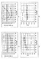
すなわち、CD−RW規格オレンジブック・パート3には、図1に示す記録パルスストラテジーが規定されている。従って現在実用化されている記録装置では、上記記録パルスストラテジー発生用IC回路を用いているのが実情である。従って、現在実用化されている記録装置では、上記記録パルスストラテジー又はこれを若干変更した記録パルスストラテジーをもって、1倍速から8〜10倍速までの広範囲な線速度の記録を行わなければならない。
【0013】
書き換え型DVDの規格である、DVD−RWやDVD+RWでも、同様の記録ストラテジーが規定されている。これら記録ストラテジーの特徴は、nTマーク長の非晶質マークをn−1個の記録パルスと冷却パルス(オフパルス)に分割して記録することである。このため、これら記録ストラテジーでは、一対の記録パルスと冷却パルスの繰り返し平均周期が約1Tとなっている。
【0014】
図1(a)はEFM変調された3T〜11Tの時間的長さを有するデータ信号であり、図1(b)は、該データ信号に基づいて発生される実際の記録光のレーザーパワーである。Pwは記録層を溶融させ急冷によって非晶質マークを形成するための記録パワー、Peは非晶質マークを結晶化によって消去するための消去パワーであり、通常、バイアスパワーPbは再生光の再生パワーPrとほぼ同じである。記録パワーPw照射区間を記録パルス、バイアスパワー照射区間をオフパルスと称する。
【0015】
EFM+変調の場合においては、上記3〜11Tの時間的長さを有するデータ信号に14Tの時間的長さを有するデータ信号が加わる。
ここで、上記記録ストラテジーでは、記録パルスとオフパルスの繰り返しの周期が基本的に、基準クロック周期Tで一定である。基準クロック周期Tは、高線速記録では、線速度に比例して高周波数化される。
【0016】
CDの1倍速基準速度では、T=231nsecであるが、24倍速ではT=9.6nsec、32倍速ではT=7.2nsecである。従って、24倍速以上の高線速度記録において図1に示す記録パルスストラテジーを用いる場合、図1における分割された記録パルス及びオフパルスの時間幅は、上記高速記録に伴う高周波数化により、5nsec未満となる。
【0017】
一方、DVDの1倍速基準速度では、T=38.2nsecであるが、6倍速では、T=6.4nsec、8倍速ではT=4.8nsecである。従って、6倍速以上の高線速度記録においては、図1における分割された記録パルス及びオフパルスの時間幅は、このような高速記録に伴う高周波数化により、3nsec以下となる。
【0018】
ところで、通常記録パワーのレーザー光照射では、立ち上がり立下りに1−3nsecは要する。このため、このような高周波においては、上記立ち上がり立下り時間が無視できなくなり、記録パルス区間の長さ及びオフパルス区間の長さは、実質的にはさらに短くなり、5nsec(CD−RWの場合)又は3nsec(RW−DVDの場合)を大幅に下回ることとなる。この際、記録パルスにおける加熱は不十分となり、必要とされる記録パワーが急激に高くなる。一方、オフパルス区間の冷却も不十分となるために、非晶質化に必要な冷却速度が得られなくなる。また、高線速記録のために、CD−RW又はRW−DVDの記録層には、一般に消去速度すなわち結晶化速度の速い材料を用いる。従って、上記オフパルス区間における冷却速度の不足は、いったん溶融された領域の再結晶化を招く。
【0019】
従って、図1に示す記録パルスストラテジーでは、CD−RWにおける24倍速以上の高速記録、又はRW−DVDにおける6倍速以上の高速記録を行うことは非常に困難となる。
本発明者らの一部は、すでに、このような問題を解決するために、記録パルスとオフパルスとの繰り返しの周期を2Tベースとする分割方法により、CDの16倍速、DVDの5倍速でのオーバーライト記録を実現した(特開2001−331936号公報)。しかしながら、このような2Tベースの分割方法を用いてもなお、CDの24倍速以上又はDVDの6倍速以上では、上記した通り、高線速記録のための高い結晶化速度を有する材料を用いる必要がある一方で、このような材料を用いると、冷却速度が不足することによる再結晶化現象がよりいっそう深刻となるのである。
【0020】
本発明の目的は、概ね20m/s以上の高速記録に用いる書き換え型光記録媒体及びその記録方法を提供することにある。
本発明の具体的な目的は、24倍速以上の高線速記録に用いるCD−RW及びその記録方法を提供することにある。より具体的には、CD−RWでは、記録層が非晶質の状態を記録マークとし、EFM変調による(即ちデータの基準クロック周期Tに対して3Tから11Tまでの時間的長さのマーク長及びマーク間長さの組み合わせによる)マーク長記録を行うことにより、記録信号フォーマットについてはCDと再生互換を有する書換え型媒体とその記録方法を提供することにある。
【0021】
本発明の具体的な目的は、6倍速以上の高線速記録に用いる書き換え型DVD記録媒体及びその記録方法を提供することにある。より具体的には、記録層が非晶質の状態を記録マークとし、EFM+変調による、即ちデータの基準クロック周期Tに対して3Tから14Tまでの時間的長さのマーク長及びマーク間長さの組み合わせによるマーク長記録を行うことにより、記録信号フォーマットについてはDVDと再生互換を有する書換え型媒体とその記録方法を提供することにある。
【0022】
【課題を解決するための手段】
本発明の第1の要旨は、案内溝が形成された基板と相変化型記録層とを有してなり、該相変化型記録層の結晶状態の部分を未記録・消去状態に対応させ、該相変化型記録層の非晶質状態の部分を記録状態に対応させて、記録光を照射することにより該記録状態に対応する非晶質マークを形成させる書き換え型光記録媒体において、
線速度1.2m/sを基準速度(1倍速)V1とし、
基準速度の24倍速の線速度V=24V1、又は32倍速の線速度V=32V1のいずれか一つを選び、
基準クロック周期TがVT=V1T1(ただし、T1は231nsecである)であるように保ちながらEFM変調された信号を下記記録方式CD1−1又は記録方式CD1−2の条件内の1つの記録方式で10回オーバーライト記録した後に、
1倍速での再生によって得られる記録信号のアイパターンの変調度m11が60〜80%であり、記録信号のアイパターンの反射率の上端値Rtopが15〜25%であり、且つ各マーク長及び各マーク間のジッタが35nsec以下、
となることを特徴とする書き換え型光記録媒体に存する。
記録方式CD1−1;
波長780nmの光を、開口数NAが0.5の光学系を介して照射する。
【0023】
この際、1つの非晶質マークの時間的長さをnT(nは3から11までの整数)としたとき、
記録マーク間に対しては、非晶質を結晶化し得る消去パワーPeを照射し、
n=2m(mは3以上の整数)なる記録マークに対しては、そのうちの時間的長さ(n−j)T、(jは−2.0〜2.0なる実数)を、
α1T、β1T、α2T、β2T、・・・・、αmT、βmT、
からなるm個のαiTとβiTとからなる区間に分割し、かつ、各区間がα1=0.7〜1.4、αi=0.7〜1.2(iは2〜m−1の整数であり、αiはかかるiによらず0.7〜1.2の間の一定値αcをとる)、β1+α2=1.7〜2.3、βi−1+αi=2(iは3〜m−1の整数)、βm−1+αm=1.7〜2.3、αm=0.7〜1.2、βm=0〜2、の順に、Σi(αi+βi)=n−jとなるように分割し、
n=2m+1(mは3以上の整数)なる記録マークに対しては、そのうちの時間的長さ(n−k)T、(kは−2.0〜2.0なる実数)を、
α1’T、β1’T、α2’T、β2’T、・・・・、αm’T、βm’T、
からなるm個のαi’Tとβi’Tとからなる区間に分割し、かつ、各区間がα1’=α1、β1’=β1+Δ1(Δ1=0.3〜0.6)、αi’=αc(i=2〜m−1の整数)、βi−1’+αi’=2(iは3〜m−1の整数)、βm−1’=βm−1+Δm−1(Δm−1=0〜0.6)、αm’=αm+Δm(0<Δm≦0.6)、Δmm=Δm−1+Δm=0.3〜0.6、βm’=βmの順に、Σi(αi’+βi’)=n−kとなるように分割し、
αiTおよびαi’Tなる時間(iは1〜mの整数)内には、記録層を溶融するに足る一定の記録パワーPwの記録光(ただし、Pwは20〜40mWであり、Pe/Pw=0.2〜0.6とする)を照射し、
βiTおよびβi’Tなる時間(iは1〜mの整数)内には、1mW未満のバイアスパワーPbの記録光を照射する。
【0024】
さらに、mが3以上の場合には、α1(=α1’)、αc、βm(=βm’)、β1、Δ1、βm−1、Δm−1、αm、Δmはmによらず一定である。
また、m=2(n=4、5)の場合には、α1、α1’、α2、α2’、β2、β2’をそれぞれmが3の場合のα1、α1’、α3、α3’、β3、β3’と等しくするとともに、β1をmが3の場合のβ1又はβ2のいずれかと等しくし、β1’をmが3の場合のβ1’又はβ2’のいずれかと等しくする。
【0025】
m=1(n=3)の場合には、一対の記録パワー照射区間α1’Tとバイアスパワー照射区間β1’Tからなる記録光の照射を行う。
記録方式CD1−2;
波長780nmの光を、開口数NAが0.5の光学系を介して照射する。
この際、1つの非晶質マークの時間的長さをnT(nは3から11までの整数)としたとき、
記録マーク間に対しては、非晶質を結晶化し得る消去パワーPeを照射し、
n=2m(mは3以上の整数)なる記録マークに対しては、そのうちの時間的長さ(n−j)T、(jは−2.0〜2.0なる実数)を、
α1T、β1T、α2T、β2T、・・・・、αmT、βmT、
からなるm個のαiTとβiTとからなる区間に分割し、かつ、各区間がα1=0.7〜1.4、αi=0.7〜1.2(iは2〜m−1の整数であり、αiはかかるiによらず0.7〜1.2の間の一定値αcをとる)、β1+α2=1.7〜2.3、βi−1+αi=2(iは3〜m−1の整数)、βm−1+αm=1.7〜2.3、αm=0.7〜1.2、βm=0〜2、の順に、Σi(αi+βi)=n−jとなるように分割し、
n=2m+1(mは3以上の整数)なる記録マークに対しては、そのうちの時間的長さ(n−k)T、(kは−2.0〜2.0なる実数)を、
α1’T、β1’T、α2’T、β2’T、・・・・、αm’T、βm’T、
からなるm個のαi’Tとβi’Tとからなる区間に分割し、かつ、各区間がα1’=α1、β1’=β1、αi’=αc(i=2〜m−1の整数)、βi−1’+αi’=2(iは3〜m−1の整数)、βm−1’=βm−1+Δm−1(Δm−1=0〜0.6)、αm’=αm+Δm(0<Δm≦0.6)、Δmm=Δm−1+Δm=0.5〜1.2、βm’=βmの順に、Σi(αi’+βi’)=n−kとなるように分割し、
αiTおよびαi’Tなる時間(iは1〜mの整数)内には、記録層を溶融するに足る一定の記録パワーPwの記録光(ただし、Pwは20〜40mWであり、Pe/Pw=0.2〜0.6とする)を照射し、
βiTおよびβi’Tなる時間(iは1〜mの整数)内には、1mW未満のバイアスパワーPbの記録光を照射する。
【0026】
さらに、mが3以上の場合には、α1(=α1’)、β1(=β1’)、αc、βm−1、Δm−1、αm、βm、Δm’はmによらず一定である。また、m=2(n=4、5)の場合には、α1、α1’、β1、β1’、α2、α2’、β2、β2’をそれぞれm=3の場合のα1、α1’、β2、β2’、α3、α3’、β3、β3’と等しくする。
【0027】
m=1(n=3)の場合には、一対の記録パワー照射区間α1’Tとバイアスパワー照射区間β1’Tからなる記録光の照射を行う。
本発明の第2の要旨は、案内溝が形成された基板と相変化型記録層とを有してなり、該相変化型記録層の結晶状態の部分を未記録・消去状態に対応させ、該相変化型記録層の非晶質状態の部分を記録状態に対応させて、記録光を照射することにより該記録状態に対応する非晶質マークを形成させる書き換え型光記録媒体において、
線速度3.49m/sを基準速度(1倍速)V1とし、
基準速度の6倍速の線速度V=6V1、8倍速の線速度V=8V1、10倍速の線速度V=10V1、及び、12倍速の線速度V=12V1のいずれか一つを選び、
基準クロック周期TがVT=V1T1(ただし、T1は38.2nsecである)であるように保ちながらEFM+変調された信号を下記記録方式DVD1−1又は記録方式DVD1−2の条件内の1つの記録方式で10回オーバーライト記録した後に、
1倍速での再生によって得られる記録信号のアイパターンの変調度m14が55〜80%であり、記録信号のアイパターンの反射率の上端値Rtopが18〜30%であり、且つ再生信号のクロックジッタが15%以下、
となることを特徴とする書き換え型光記録媒体に存する。
記録方式DVD1−1;
波長650nmの光を、開口数NAが0.65の光学系を介して照射する。
【0028】
この際、1つの非晶質マークの時間的長さをnT(nは3〜11の整数と14)としたとき、
記録マーク間に対しては、非晶質を結晶化し得る消去パワーPeを照射し、
n=2m(mは3以上の整数)なる記録マークに対しては、そのうちの時間的長さ(n−j)T、(jは−2.0〜2.0なる実数)を、
α1T、β1T、α2T、β2T、・・・・、αmT、βmT、
からなるm個のαiTとβiTとからなる区間に分割し、かつ、各区間がα1=0.7〜1.4、αi=0.7〜1.2(iは2〜m−1の整数であり、αiはかかるiによらず0.7〜1.2の間の一定値αcをとる)、β1+α2=1.7〜2.3、βi−1+αi=2(iは3〜m−1の整数)、βm−1+αm=1.7〜2.3、αm=0.7〜1.2、βm=0〜2、の順に、Σi(αi+βi)=n−jとなるように分割し、
n=2m+1(mは3以上の整数)なる記録マークに対しては、そのうちの時間的長さ(n−k)T、(kは−2.0〜2.0なる実数)を、
α1’T、β1’T、α2’T、β2’T、・・・・、αm’T、βm’T、
からなるm個のαi’Tとβi’Tとからなる区間に分割し、かつ、各区間がα1’=α1、β1’=β1+Δ1(Δ1=0.3〜0.6)、αi’=αc(i=2〜m−1の整数)、βi−1’+αi’=2(iは3〜m−1の整数)、βm−1’=βm−1+Δm−1(Δm−1=0〜0.6)、αm’=αm+Δm(0<Δm≦0.6)、Δmm=Δm−1+Δm=0.3〜0.6、βm’=βmの順に、Σi(αi’+βi’)=n−kとなるように分割し、
αiTおよびαi’Tなる時間(iは1〜mの整数)内には、記録層を溶融するに足る一定の記録パワーPwの記録光(ただし、Pwは10〜40mWであり、Pe/Pw=0.2〜0.6とする)を照射し、
βiTおよびβi’Tなる時間(iは1〜mの整数)内には、1mW未満のバイアスパワーPbの記録光を照射する。
【0029】
さらに、mが3以上の場合には、α1(=α1’)、αc、βm(=βm’)、β1、Δ1、βm−1、Δm−1、αm、Δmはmによらず一定である。
また、m=2(n=4、5)の場合には、α1、α1’、α2、α2’、β2、β2’をそれぞれmが3の場合のα1、α1’、α3、α3’、β3、β3’と等しくするとともに、β1をmが3の場合のβ1又はβ2のいずれかと等しくし、β1’をmが3の場合のβ1’又はβ2’のいずれかと等しくする。
【0030】
m=1(n=3)の場合には、一対の記録パワー照射区間α1’Tとバイアスパワー照射区間β1’Tからなる記録光の照射を行う。
記録方式DVD1−2;
波長650nmの光を、開口数NAが0.65の光学系を介して照射する。
この際、1つの非晶質マークの時間的長さをnT(nは3〜11の整数と14)としたとき、
記録マーク間に対しては、非晶質を結晶化し得る消去パワーPeを照射し、
n=2m(mは3以上の整数)なる記録マークに対しては、そのうちの時間的長さ(n−j)T、(jは−2.0〜2.0なる実数)を、
α1T、β1T、α2T、β2T、・・・・、αmT、βmT、
からなるm個のαiTとβiTとからなる区間に分割し、かつ、各区間がα1=0.7〜1.4、αi=0.7〜1.2(iは2〜m−1の整数であり、αiはかかるiによらず0.7〜1.4の間の一定値αcをとる)、β1+α2=1.7〜2.3、βi−1+αi=2(iは3〜m−1の整数)、βm−1+αm=1.7〜2.3、αm=0.7〜1.2、βm=0〜2、の順に、Σi(αi+βi)=n−jとなるように分割し、
n=2m+1(mは3以上の整数)なる記録マークに対しては、そのうちの時間的長さ(n−k)T、(kは−2.0〜2.0なる実数)を、
α1’T、β1’T、α2’T、β2’T、・・・・、αm’T、βm’T、
からなるm個のαi’Tとβi’Tとからなる区間に分割し、かつ、各区間がα1’=α1、β1’=β1、αi’=αc(i=2〜m−1の整数)、βi−1’+αi’=2(iは3〜m−1の整数)、βm−1’=βm−1+Δm−1(Δm−1=0〜0.6)、αm’=αm+Δm(0<Δm≦0.6)、Δmm=Δm−1+Δm=0.5〜1.2、βm’=βmの順に、Σi(αi’+βi’)=n−kとなるように分割し、
αiTおよびαi’Tなる時間(iは1〜mの整数)内には、記録層を溶融するに足る一定の記録パワーPwの記録光(ただし、Pwは10〜40mWであり、Pe/Pw=0.2〜0.6とする)を照射し、
βiTおよびβi’Tなる時間(iは1〜mの整数)内には、1mW未満のバイアスパワーPbの記録光を照射する。
【0031】
さらに、mが3以上の場合には、α1(=α1’)、β1(=β1’)、αc、βm−1、Δm−1、αm、βm、Δm’はmによらず一定である。また、m=2(n=4、5)の場合には、α1、α1’、β1、β1’、α2、α2’、β2、β2’をそれぞれm=3の場合のα1、α1’、β2、β2’、α3、α3’、β3、β3’と等しくする。
【0032】
m=1(n=3)の場合には、一対の記録パワー照射区間α1’Tとバイアスパワー照射区間β1’Tからなる記録光の照射を行う。
本発明の第3の要旨は、書換え型光記録媒体に対して、情報を複数の記録マーク長及び記録マーク間長により記録するにあたり、
記録マーク間に対しては、非晶質を結晶化しうる消去パワーPeの光を照射して記録マーク間を形成するとともに、
一つの記録マークの時間的長さをnT(Tは基準クロック周期)としたときに、
n=2m(mは1以上の整数)なる記録マークに対しては、そのうちの時間的長さ(n−j)T(jは−2.0〜2.0なる実数)を、
α1T、β1T、α2T、β2T、・・・・、αmT、βmT、
からなるm個のαiTとβiTからなる区間(ただしΣi(αi+βi)=n−j)に分割し、
n=2m+1(mは1以上の整数)なる記録マークに対しては、そのうちの時間的長さ(n−k)T、(kは−2.0〜2.0なる実数)を、
α1’T、β1’T、α2’T、β2’T、・・・・、αm’T、βm’T、
からなるm個のαi’Tとβi’Tからなる区間(ただし、Σi(αi’+βi’)=n−k)に分割し、
αiTおよびαi’Tなる時間(iは1〜mの整数)内には、記録層を溶融するに足る一定の記録パワーPwの光を照射し、
βiTおよびβi’Tなる時間(iは1〜mの整数)内には、バイアスパワーPbの光を照射することによって、時間的長さnTの記録マークを形成する書換え型光記録媒体への記録方法であって、
m≧3では、
n=2mの記録マークにおいては、nTマークの開始時間をT0とするとき、
(i)T0から遅延時間Td1T後にα1Tが発生された後、
(ii)i=2〜mにおいては、βi−1+αiが概ね周期2(但し、i=2及び/又はi=mにおけるβi−1+αiは、±0.5の範囲で概ね周期2からずらしてもよい。また、m≧4の場合、i=3〜m−1においてはβi−1及びαiは、それぞれ一定値βc及びαcをとる。)を保ちながら、βi−1T及びαiTがこの順に交互に発生された後、
(iii)βmTが発生され、
n=2m+1の記録マークにおいては、nTマークの開始時間をT0とするとき、
(i)T0から遅延時間Td1’T後にα1’Tが発生された後、
(ii)i=2〜mでおいては、βi−1’+αi’が概ね周期2(但し、i=2及び/又はi=mにおけるβi−1’+αi’は、±2の範囲で概ね周期2からずらしてもよい。また、m≧4の場合、i=3〜m−1においてはβi−1’及びαi’は、それぞれ一定値βc及びαcをとる。)を保ちながら、βi−1’T及びαi’Tがこの順に交互に発生された後、
(iii)βm’Tが発生され、
同一のmにおける、n=2mの記録マーク及びn=2m+1の記録マークにおいて、Td1=Td1’、α1=α1’、β1=β1’、αm≠αm’とし、かつ(βm−1とβm−1’)又は(βmとβm’)の一組以上が異なる値をとることを特徴とする書換え型光記録媒体への記録方法に存する。
【0033】
尚、本発明において、「□が○〜△の範囲」と記載する場合、これは「○≦□≦△」を意味する。
【0034】
【発明の実施の形態】
1.媒体の特性について
1−1.CD−RWの場合
本発明をCD−RWに適用する場合においては、記録光による光スポットの媒体に対する速度である線速度として1.2m/s〜1.4m/s、特には1.2m/sを基準速度:V1、即ち1倍速とする。
【0035】
まず、本発明の第1及び第2の要旨に係るディスクについて説明する。
本発明の書換え型光記録媒体は、通常円盤状である。そして相変化型記録層の結晶状態の部分を未記録状態・消去状態とし、非晶質状態の部分を記録状態とする。記録される情報は、レーザー光などの記録光を照射し非晶質マークを形成することにより、EFM変調された信号からなる。媒体の基板には通常螺旋状の溝が形成される。また、非晶質マークは通常溝内に形成される。ここで、溝とは、基板面上に形成された光ビーム案内用の凹形状の底部であり、記録再生光入射側から見て近い方の面を言う。該溝は、好ましくは1倍速に換算したときに22.05kHzとなる搬送周波数を基準とする周波数で半径方向に蛇行(ウォブル)しており、このような溝をウォブル溝と呼ぶ。そして、上記搬送周波数が±1kHzの周波数で周波数変調され、この微妙な周波数変化により、ディスク上のアドレス情報が絶対時間情報として組み込まれている。このような絶対時間情報はATIP(Absolute Time In Pre−groove)信号と呼ばれる。
【0036】
このウォブル溝は、CLVモードで、CDの1倍速の線速でスタンパー上に形成したのち、このスタンパーをもとに基板を射出成形することで形成することができる。記録容量を高めるため、通常搬送周波数が線速1.2m/s(±0.1m/sの範囲で許容)において22.05kHzとなるようにウォブル溝は形成される。
【0037】
データを記録する際には、基準クロック周期Tが基準となり、この整数倍の長さを有する様々な時間的長さのマーク及びスペース(マーク間)を形成することでデータを記録する。EFM変調においては通常時間的長さ3T〜11Tのマークが形成される。また、基準クロック周期Tは記録線速に反比例して変化させるのが通常である。
【0038】
基準クロック周期Tの逆数は基準クロック周波数と呼ばれ、CDの1倍速(線速度1.2m/s〜1.4m/s)における基準クロック周波数は、データの1チャネルビットに相当し、通常4.3218MHzである。この基準クロック周波数は、上記ウォブルの基準周波数22.05kHzのちょうど196倍となっている。
【0039】
1倍速における基準クロック周期Tは通常1/(4.3218×106 )=231×10−9(秒)=231(ナノ秒)となる。
以下の説明では、特に断わりのない限り基準クロック周期Tと線速Vとの積VTは線速によらず一定とする。
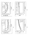
図2(a)に、CD−RWをはじめとするCDファミリーで用いられるEFM変調信号の再生波形(アイパターン)の模式図を示す。アイパターンには、3Tから11Tのすべての非晶質マーク及び結晶状態のスペースの再生波形が実質的にランダムに含まれている。再生波形は、反射光強度を電圧信号として取り出しオシロスコープ上で観察した波形である。この際、再生信号は直流成分を含んでいる。
【0040】
アイパターンの上端Itopを入射光に対する反射率に換算したものがスペースに対応する反射率の上端値Rtopであり、アイパターンの振幅(実際上は、11Tマークの振幅)I11をItopで規格化したものが下記式(1)で表される記録信号のアイパターンの変調度m11(本明細書においては、m11を単に変調度という場合がある。)である。
【0041】
m11=I11/Itop×100(%) (1)
本発明においては、変調度m11は60%以上80%以下とする。変調度は光学的分解能に依存するのでNAが大きな光学系では大きく見える傾向があるため、本発明においては波長約780nmのレーザー光を、開口数NA=0.5の光学系を通して照射し記録する際の変調度m11とする。ただし波長は厳密に780nmである必要はなく、775〜795nm程度の範囲にあれば良い。
【0042】
信号振幅I11は大きいほうが好ましいが、大きすぎると信号再生系のアンプのゲインが極端に飽和してしまうためm11の上限は80%、好ましくは78%、さらに好ましくは75%程度である。一方、小さすぎると信号体雑音比(SN比)が低下してしまうため、下限は60%、好ましくは62%、さらに好ましくは65%程度である。また、Rtopは15〜25%、好ましくは15〜20%、さらに好ましくは16〜19%の範囲とする。さらに、下記式(2)
Asym =(Islice/I11−1/2)(%) (2)
で定義されるアシンメトリー値Asymは、できるだけ0付近にあることが望ましいが、通常は±10%の範囲である。ここで、Isliceは、図2(a)におけるIの中心線2001と包絡線の底辺2002との間の電圧差であり、I11は包絡線(envelop)の上辺2003と底辺2002との間の電圧値である。
【0043】
EFM変調に用いられる3T〜11Tの各マーク長及びスペース長のジッタ(jitter)、及びデビエーション(deviation)は、以下のように決められる。すなわち、3T〜11Tの各マーク長及びスペース長のデビエーション(deviation)は、図2(a)における再生信号を高域通過フィルタを通過させてRF成分を取り出した後に、信号振幅の実質的な中心値となるゼロレベルを閾値としてDCスライスして得られる、マーク長あるいはスペース長の平均値の所定値(nT:n=3〜11)からのずれ(デビエーション)であり、ジッタ(jitter)は、その標準偏差(ジッター)である。詳細な測定方法は、CD規格であるレッドブック、CD−RW規格であるオレンジブックや、「CDファミリー」(オーム社発行、平成8年4月25日)で規定されている。本発明においては、ジッタについては、1倍速(基準クロック周期231ナノ秒)で再生したときのジッタ値が35ナノ秒以下、好ましくは30ナノ秒以下、さらに好ましくは25ナノ秒以下とする。
【0044】
なお、通常3Tのマーク長もしくはスペース長のジッタが3T〜11Tの中で最も悪い値となることが多い。さらに、3Tスペース長ジッタが3Tマーク長ジッタより悪い値となることが多い。
本発明においては、デビエーションは通常3Tで±40ナノ秒以下、11Tで±60ナノ秒以下とする。なお、4T〜10Tに対しては、通常3及び11Tに対する規定である±40ナノ秒以下及び±60ナノ秒以下を補完して得られる値となる。いずれにせよ、デビエーションは、概ね基準クロック周期Tの±20%程度以内であればよい。
【0045】
なお、記録後の信号の品質に関しては、基本的に現行の規格と同様の特性を満たすのが好ましい。詳細には、オレンジブック・パート3に記載された内容を満足するのが好ましい。
変調度m11、反射率の上端値Rtop及びジッターを上記の値とすることにより、従来のCD−RW規格と互換性を維持しつつ、24倍速以上のような高速記録された媒体を、既存のCD−RW対応の再生系で再生することができる。
【0046】
本発明の書き換え型光記録媒体において好ましいのは、24倍速の線速度での記録において、3Tマーク(時間的長さ3Tを有するマーク。ただしTはデータ基準クロック周期)と3Tスペース(時間的長さ3Tを有するマーク間部)とからなる単一周期信号を記録後、11Tマーク(時間的長さ11Tを有するマーク)と11Tスペース(時間的長さ11Tを有するマーク間部)とからなる単一周期信号をオーバーライトしたときの3Tマークの消去比が20dB以上とすることである。上記消去比は、より好ましくは25dB以上とする。また、好ましくは、32倍速においても、上記消去比を20dB以上、好ましくは25dB以上とする。高線速での消去比が高い媒体ほど非晶質マーク消去時の再結晶化速度が速く、より高線速でEFM信号のオーバーライトが可能である。例えば、32倍速における上記消去比を20dB以上としておけば、24倍速で使用した際に良好な特性が得られるのは勿論、24倍速以下で使用した際にも良好な特性が得られる。ここで、3Tマークと3Tスペース(マーク間)からなる単一周期信号を記録、及び11Tマークと11Tスペースからなる単一周期信号をオーバーライトするにおいては、後述の記録方式CD1−1、1−2の記録方式を用いる。すなわち、3Tマークと3Tスペース(マーク間)からなる単一周期信号を記録するにあたっては、3Tマークを1個の記録パルスPwと後続のオフパルスPb(0<Pb<1mW)からなる記録パワーで記録し、他の区間では消去パワーPeを照射する。Pwは記録層を溶融するためのパワーであり、PbはPw照射後、溶融領域を急冷して非晶質化させるための冷却パワーである。11Tマークと11Tスペースからなる単一周期信号をオーバーライトするにあたっては、11Tマークを5個の記録パルスPwと個々のPwに付随するオフパルスPb(0<Pb<1mW)からなる記録パワーの繰り返しで記録し、他の区間では消去パワーPeを照射する。3Tデータ及び11Tデータのオーバーライトにおいては、同一のPe及びPwを使用し、Pe/Pwを0.2〜0.6の範囲で一定としながら、Peを変化させて消去比のPe依存性を測定し、いずれかのPeにおいて、消去比が20dB以上、好ましくは25dB以上となることを確認する。消去比は、11Tデータのオーバーライトの前後における3Tデータのキャリアレベルの低下率をdB単位で測定したものである。
【0047】
いずれの場合にも、同一溝内への記録を行い、通常は、1周分の溝に記録を行う。
オーバーライトを行う線速度範囲の上限における消去比が十分な値であれば、消去比が低線速側で不足することはない。線速Vで移動する開口数NAの対物レンズで集光された波長λの光ビームで記録層が照射される時間は、λ/(NA・V)で規格化されるから、低線速ほど照射時間は長くなり再結晶化に要する時間を十分確保できるからである。
【0048】
なお、3Tマーク及び11Tマークをオーバーライトしてオーバーライト消去比を測定する場合の記録方式は、後述の記録方式CD1−1、1−2、及び1−3のいずれかを用いることができるが、特に記録方式CD1−3を用いることが好ましい。記録方式CD1−3を用いる場合、消去比の測定においては、特にジッタの低い記録条件を用いる必要はないから、11Tマークの記録に際しては、βm’=0.5の暫定値を使用してかまわない
なお、消去比の測定方法において、消去パワーPeを直流(direct current、DC)的に照射しながら、記録済みのマークのキャリアレベルの低減率をデシベル値にて測定する場合があり、これをDC消去率という。DC消去率の測定では、Peを可変として最大の消去比が得られる場合の消去比を用いる。前述のオーバーライト消去比に比べて、1−2dB程度高い値となる場合があるが、このような補正値を考慮すれば、オーバーライト消去率測定をDC消去率測定によって代替することも可能である。
【0049】
また、あらかじめ記録された記録信号のジッタが1倍速再生において35nsec(ナノ秒)に達するまでの時間を該記録媒体のアーカイバル寿命とするとき、温度80℃、相対湿度85%におけるアーカイバル寿命が200時間以上であること、より好ましくは500時間以上が望ましい。
さらに、本発明においては、上記特性を満足するために、より短時間で評価可能な条件として105℃以上での加速試験を適用し、変調度m11及び、結晶状態の反射率の上端値Rtop(本明細書においては、単にRtopという場合がある。)のいずれもが、温度105℃の加速試験環境下で3時間後もその初期値の好ましくは80%以上を維持し、より好ましくは90%以上を維持する。これは、現在市販されている1−4倍速対応のCD−RWがこの要件を満足するからである。特に上記加速試験後のm11を、初期値の好ましくは80%以上を維持し、より好ましくは90%以上を維持するようにすれば、後述の記録層の結晶化温度を概ね150℃以上とすることができるようになる。
【0050】
本発明における、線速又は線速度V(この段落ではVは24倍速又は32倍速の線速度を示す。)における変調度m11、Rtop、各マーク及びマーク間のジッター、デビエーション、アシンメトリー値、消去比等の規定は、線速1.2m/sを基準速度(1倍速)V1としたとき、線速Vにおいて、データ基準クロック周期TがVT=V1T1(ただし、T1は231nsecである)であるように保ちながらEFM変調された信号を下記記録方式CD1−1又は記録方式CD1−2いずれかの条件内のある1つの記録方式で10回オーバーライト記録した後に、1倍速での再生によって得られる記録信号から与えられる。
記録方式CD1−1;
波長780nmの光を、開口数NAが0.5の光学系を介して照射する。
【0051】
この際、1つの非晶質マークの時間的長さをnT(nは3から11までの整数)としたとき、
記録マーク間に対しては、非晶質を結晶化し得る消去パワーPeを照射し、
n=2m(mは3以上の整数)なる記録マークに対しては、そのうちの時間的長さ(n−j)T、(jは−2.0〜2.0なる実数)を、
α1T、β1T、α2T、β2T、・・・・、αmT、βmT、
からなるm個のαiTとβiTとからなる区間に分割し、かつ、各区間がα1=0.7〜1.4、αi=0.7〜1.2(iは2〜m−1の整数であり、αiはかかるiによらず0.7〜1.2の間の一定値αcをとる)、β1+α2=1.7〜2.3、βi−1+αi=2(iは3〜m−1の整数)、βm−1+αm=1.7〜2.3、αm=0.7〜1.2、βm=0〜2、の順に、Σi(αi+βi)=n−jとなるように分割し、
n=2m+1(mは3以上の整数)なる記録マークに対しては、そのうちの時間的長さ(n−k)T、(kは−2.0〜2.0なる実数)を、
α1’T、β1’T、α2’T、β2’T、・・・・、αm’T、βm’T、
からなるm個のαi’Tとβi’Tとからなる区間に分割し、かつ、各区間がα1’=α1、β1’=β1+Δ1(Δ1=0.3〜0.6)、αi’=αc(i=2〜m−1の整数)、βi−1’+αi’=2(iは3〜m−1の整数)、βm−1’=βm−1+Δm−1(Δm−1=0〜0.6)、αm’=αm+Δm(0<Δm≦0.6)、Δmm=Δm−1+Δm=0.3〜0.6、βm’=βmの順に、Σi(αi’+βi’)=n−kとなるように分割し、
αiTおよびαi’Tなる時間(iは1〜mの整数)内には、記録層を溶融するに足る一定の記録パワーPwの記録光(ただし、Pwは20〜40mWであり、Pe/Pw=0.2〜0.6とする)を照射し、
βiTおよびβi’Tなる時間(iは1〜mの整数)内には、1mW未満のバイアスパワーPbの記録光を照射する。
【0052】
さらに、mが3以上の場合には、α1(=α1’)、αc、βm(=βm’)、β1、Δ1、βm−1、Δm−1、αm、Δmはmによらず一定である。
また、m=2(n=4、5)の場合には、α1、α1’、α2、α2’、β2、β2’をそれぞれmが3の場合のα1、α1’、α3、α3’、β3、β3’と等しくするとともに、β1をmが3の場合のβ1又はβ2のいずれかと等しくし、β1’をmが3の場合のβ1’又はβ2’のいずれかと等しくする(但し、±10%程度のずれは許容するものとする)。
【0053】
m=1(n=3)の場合には、一対の記録パワー照射区間α1’Tとバイアスパワー照射区間β1’Tからなる記録光の照射を行う。
記録方式CD1−2;
波長780nmの光を、開口数NAが0.5の光学系を介して照射する。
この際、1つの非晶質マークの時間的長さをnT(nは3から11までの整数)としたとき、
記録マーク間に対しては、非晶質を結晶化し得る消去パワーPeを照射し、
n=2m(mは3以上の整数)なる記録マークに対しては、そのうちの時間的長さ(n−j)T、(jは−2.0〜2.0なる実数)を、
α1T、β1T、α2T、β2T、・・・・、αmT、βmT、
からなるm個のαiTとβiTとからなる区間に分割し、かつ、各区間がα1=0.7〜1.4、αi=0.7〜1.2(iは2〜m−1の整数であり、αiはかかるiによらず0.7〜1.2の間の一定値αcをとる)、β1+α2=1.7〜2.3、βi−1+αi=2(iは3〜m−1の整数)、βm−1+αm=1.7〜2.3、αm=0.7〜1.2、βm=0〜2、の順に、Σi(αi+βi)=n−jとなるように分割し、
n=2m+1(mは3以上の整数)なる記録マークに対しては、そのうちの時間的長さ(n−k)T、(kは−2.0〜2.0なる実数)を、
α1’T、β1’T、α2’T、β2’T、・・・・、αm’T、βm’T、
からなるm個のαi’Tとβi’Tとからなる区間に分割し、かつ、各区間がα1’=α1、β1’=β1、αi’=αc(i=2〜m−1の整数)、βi−1’+αi’=2(iは3〜m−1の整数)、βm−1’=βm−1+Δm−1(Δm−1=0〜0.6)、αm’=αm+Δm(0<Δm≦0.6)、Δmm=Δm−1+Δm=0.5〜1.2、βm’=βmの順に、Σi(αi’+βi’)=n−kとなるように分割し、
αiTおよびαi’Tなる時間(iは1〜mの整数)内には、記録層を溶融するに足る一定の記録パワーPwの記録光(ただし、Pwは20〜40mWであり、Pe/Pw=0.2〜0.6とする)を照射し、
βiTおよびβi’Tなる時間(iは1〜mの整数)内には、1mW未満のバイアスパワーPbの記録光を照射する。
【0054】
さらに、mが3以上の場合には、α1(=α1’)、β1(=β1’)、αc、βm−1、Δm−1、αm、βm、Δm’はmによらず一定である。また、m=2(n=4、5)の場合には、α1、α1’、β1、β1’、α2、α2’、β2、β2’をそれぞれm=3の場合のα1、α1’、β2、β2’、α3、α3’、β3、β3’と等しくする(但し、±10%程度のずれは許容するものとする)。
【0055】
m=1(n=3)の場合には、一対の記録パワー照射区間α1’Tとバイアスパワー照射区間β1’Tからなる記録光の照射を行う。
なお、Σi(αi+βi)等は、iに関して1〜mまでの和をとることを意味する。
本発明においては、上記基準線速の24倍速又は32倍速で書き換え可能なCD−RWディスクにおいては、基準線速の8倍速、10倍速、12倍速、16倍速又は20倍速の少なくともいずれか一つの線速においても、変調度m11、Rtop、各マーク及びマーク間のジッター、デビエーション、アシンメトリー値、消去比の値が上記数値範囲となるようにするのが好ましい。
【0056】
さらに、上記基準速度の8倍速、10倍速、12倍速、16倍速、及び20倍速のいずれか少なくとも一つの線速度をVminとし、基準速度の24倍速又は32倍速をVmaxとした場合に、VminとVmaxとの間の全ての線速度Vにおいても、変調度m11、Rtop、ジッター、デビエーション、アシンメトリー値、消去比の値が前記数値範囲となるようにするのが好ましい。これにより、後述のP−CAV又はCAV方式での記録が可能となる。
【0057】
ここで、8倍速、10倍速、12倍速、16倍速又は20倍速における変調度m11、Rtop、ジッター、デビエーション、アシンメトリー値、消去比等の規定は、以下のようにして測定される。すなわち、線速1.2m/sを基準速度(1倍速)V1としたとき、基準速度の8倍速(8V1)、10倍速(10V1)、12倍速(12V1)、16倍速(16V1)、又は20倍速(20V1)のいずれか一つにおいて、データ基準クロック周期TがVT=V1T1(ただし、T1は231nsecであり、Vは、10V1、12V1、16V1、及び20V1のいずれかである。)であるように保ちながらEFM変調された信号を下記記録方式CD2−1乃至は2−2のいずれかの条件内の一つの記録方式で10回オーバーライト記録した後に、1倍速での再生によって得られる記録信号から与えられる。
記録方式CD2−1;
波長780nmの光を、開口数NAが0.5の光学系を介して照射する。
【0058】
この際、1つの非晶質マークの時間的長さをnT(nは3から11までの整数)としたとき、
記録マーク間に対しては、非晶質を結晶化し得る消去パワーPeを照射し、
n=2m(mは3以上の整数)なる記録マークに対しては、そのうちの時間的長さ(n−j)T、(jは−2.0〜2.0までの実数)を、
α1T、β1T、α2T、β2T、・・・・、αmT、βmT、
からなるm個のαiTとβiTとからなる区間に分割し、かつ、各区間がα1=0.1〜1、αi=0.1〜1(iは2〜m−1の整数であり、αiはかかるiによらず0.1〜1の間の一定値αcをとる)、β1+α2=1.7〜2.3、βi−1+αi=2(iは3〜m−1の整数)、βm−1+αm=1.7〜2.3、αm=0.1〜1、βm=0〜2、の順に、Σi(αi+βi)=n−jとなるように分割し、
n=2m+1(mは3以上の整数)なる記録マークに対しては、そのうちの時間的長さ(n−k)T、(kは−2.0〜2.0までの実数)を、
α1’T、β1’T、α2’T、β2’T、・・・・、αm’T、βm’T、
からなるm個のαi’Tとβi’Tとからなる区間に分割し、かつ、各区間がα1’=α1、β1’=β1+Δ1(Δ1=0.3〜0.6)、αi’=αc(iは2〜m−1の整数)、βi−1’+αi’=2(iは3〜m−1の整数)、βm−1’=βm−1+Δm−1(Δm−1=0〜0.6)、αm’=αm+Δm(0<Δm≦0.6)、Δmm=Δm−1+Δm=0.3〜0.6、βm’=βmの順に、Σi(αi’+βi’)=n−kとなるように分割し、
αiTおよびαi’Tなる時間(iは1〜mの整数)内には、記録層を溶融するに足る一定の記録パワーPwの記録光(ただし、Pwは20〜40mWであり、Pe/Pw=0.2〜0.6とする)を照射し、
βiTおよびβi’Tなる時間(iは1〜mの整数)内には、1mW未満のバイアスパワーPbの記録光を照射する。
【0059】
さらに、mが3以上の場合には、α1(=α1’)、αc、βm(=βm’)、β1、Δ1、βm−1、Δm−1、αm、Δmはmによらず一定である。
また、m=2(n=4、5)の場合には、α1、α1’、α2、α2’、β2、β2’をそれぞれmが3の場合のα1、α1’、α3、α3’、β3、β3’と等しくするとともに、β1をmが3の場合のβ1又はβ2のいずれかと等しくし、β1’をmが3の場合のβ1’又はβ2’のいずれかと等しくする(但し、±10%程度のずれは許容するものとする)。但し、m=2におけるβ2’に関しては、さらに±0.5の範囲において値を変更しうるものとする。
【0060】
m=1(n=3)の場合には、一対の記録パワー照射区間α1'Tとバイアスパワー照射区間β1'Tからなる記録光の照射を行う。
記録方式CD2−2;
波長780nmの光を、開口数NAが0.5の光学系を介して照射する。
この際、1つの非晶質マークの時間的長さをnT(nは3から11までの整数)としたとき、
記録マーク間に対しては、非晶質を結晶化し得る消去パワーPeを照射し、
n=2m(mは3以上の整数)なる記録マークに対しては、そのうちの時間的長さ(n−j)T、(jは−2.0〜2.0までの実数)を、
α1T、β1T、α2T、β2T、・・・・、αmT、βmT、
からなるm個のαiTとβiTとからなる区間に分割し、かつ、各区間がα1=0.1〜
1、αi=0.1〜1(iは2〜m−1の整数であり、αiはかかるiによらず0.1〜1の間の一定値αcをとる)、β1+α2=1.7〜2.3、βi-1+αi=2(iは3〜m−1の整数)、βm-1+αm=1.7〜2.3、αm=0.1〜1、βm=0〜2、の順に、Σi(αi+βi)=n−jとなるように分割し、
n=2m+1(mは3以上の整数)なる記録マークに対しては、そのうちの時間的長さ(n−k)T、(kは−2.0〜2.0までの実数)を、
α1'T、β1'T、α2'T、β2'T、・・・・、αm'T、βm'T、
からなるm個のαi'Tとβi'Tとからなる区間に分割し、かつ、各区間がα1=α1、β1'=β1、αi'=αc(iは2〜m−1の整数)、βi-1'+α i ’=2(iは3〜m−1の整数)、βm-1'=βm-1+Δm-1(Δm-1=0〜0.6)、αm'=αm+Δm(0<Δm≦0.6)、Δmm=Δm-1+Δm=0.5〜1.2、βm'=βm+Δm'(Δm'=0〜1)の順に、
Σi(αi'+βi')=n−kとなるように分割し、
αiTおよびαi'Tなる時間(iは1〜mの整数)内には、記録層を溶融するに足る一定の記録パワーPwの記録光(ただし、Pwは20〜40mWであり、Pe/Pw=0.2〜0.6とする)を照射し、
βiTおよびβi'Tなる時間(iは1〜mの整数)内には、1mW未満のバイアスパワーPbの記録光を照射する。
【0061】
さらに、mが3以上の場合には、α1(=α1’)、β1(=β1’)、αc、βm−1、Δm−1、αm、βm、Δm’はmによらず一定である。
また、m=2(n=4、5)の場合には、α1、α1’、β1、β1’、α2、α2’、β2、β2’をそれぞれm=3の場合のα1、α1’、β2、β2’、α3、α3’、β3、β3’と等しくする(但し、±10%程度のずれは許容するものとする)。
【0062】
m=1(n=3)の場合には、一対の記録パワー照射区間α1’Tとバイアスパワー照射区間β1’Tからなる記録光の照射を行う。
ここに、記録方式CD1−1、1−2、2−1及び2−2において、j,kはnごとに異なる値をとっても良い。また、Pw、Pb、Peは一定のパワ−レベルであり、Pb≦Pe≦Pwとしている。そして、記録方式CD1−1、1−2又は記録方式CD2−1、2−2をもちいて、EFMランダムパターンの記録を行うのであるが、Pe/Pw比は0.2〜0.6の間のいずれかの値で一定にして、Pwを20〜40mWの間で変化させ、最も良好な特性が得られるPwにおいて、各マーク長及びマーク間のジッタ、m11、及びRtopがそれぞれ、上記の値を満足すればよい。ここで、パワー値Pw,Pe,Pb等は、記録光ビームのうちの主ビームのみのパワーをいい、いわゆる3ビーム法におけるサーボ用のサブビームのように記録に直接関係のないビームに配分されるパワーは除いて考える。Pe/Pw比に関しては、まず、0.3〜0.4の間の値を採用し、その結果、上記のm11、Rtop、アシンメトリー、デビエーション等の要件が満足されなければ、0.2〜0.3あるいは、0.3〜0.6の間の値を用いる。
【0063】
また、記録パルス区間αiT、αi’T、オフパルス区間βiT及びβi’Tのそれぞれにおける光のパワーレベルは、記録パルス区間ではPwでオフパルス区間ではPbで一定とする。ただし、高周波重畳を印可する場合は、Pw及びPbはその区間における平均パワーで定義する。さらに、レーザーダイオードの応答上やむを得ないオーバーシュート、アンダーシュートは許容する。記録パルスαiT及びαi’Tの立ち上がり立ち下がりは、約3nsec以下とするが、1nsec以上2nsec以下とすることが好ましい。
【0064】
記録方式CD1−1及び1−2は、特開2001−331936号公報に示されたような、記録パルス(Pw照射区間)とオフパルス(Pb照射区間)とを周期2Tを基本とする繰り返し周期で交互に発生させる記録パルス分割方法にさらに検討を加えたものである。すなわち、本発明においては、上記2T周期をベースとする記録ストラテジーのうち、特に、24乃至は32倍速でオーバーライト可能なCD−RWに適し、かつ、特に産業上有用な低コストかつ簡便な記録パルス分割方法を見出した。本発明の記録パルスストラテジーを用いることにより、複数のドライブで記録しても記録品位が保ちやすく互換性が確保しやすい記録媒体とその記録方法が提供されるようになる。
【0065】
そのために、本発明においては、周期2Tを基本とする記録パルス分割方法における可変とすべきパラメータとその範囲を限定する。そして本発明においては、上記周期2Tを基本とする記録パルス分割方法における数あるパラメータのうち、24倍速又は32倍速における記録品位を良好に保つために必要な最低限のパラメータを見出してこれを変化させている。可変とするパラメータの数を多くすれば24倍速又は32倍速での良好な記録の達成は比較的容易とある。しかし、数多くのパラメータを可変とすることは、光記録媒体に記録を行う記録装置におけるパルス発生の電子回路(集積回路)の設計をいたずらに複雑にするだけである。このため、本発明においては上記電子回路(集積回路)の設計を容易にしつつ、かつ24倍速記録又は32倍速記録を良好に行うことができるCD−RWを実現できるような最低限のパラメータを見出したのである。
【0066】
24倍速又は32倍速で良好な記録を行うために可変とすべき最低限のパラメータは、24倍速乃至は32倍速でオーバーライト可能な記録媒体の検討とパルス分割記録方法とを相互にフィードバックをかけながら検討を行うことにより実現できるものである。従って、本発明は、記録媒体と記録方法とを同時に実現するという高度な創作により実現されたものである。
【0067】
このような検討により、本発明においては、未だ実現されていない8あるいは10倍速から24あるいは32倍速という極めて広範囲の線速度で、記録及び再生の互換性の高いCD−RW記録媒体と記録方法を提供することができるようになるのである。
CD−RWにおけるEFM変調の場合、マーク長nTは、n=3,4,5,6,7,8,9,10,11の場合があるが、それぞれを、m=1,2,2,3,3,4,4,5,5個の2Tを基本とする周期に分割し、m個の記録パルスとオフパルスの組に分割した記録パルスで記録を行う。本発明では、24倍速又は32倍速でオーバーライト可能なCD−RW記媒体を明確に規定するために、特に記録方式CD1−1、及び1−2に示したような限定を行っている。
【0068】
図3は、上記記録方式CD1−1、及び2−1におけるパルス分割方法を実施する場合の、各記録パルスの関係の一例を示した図である。尚、図3(b)におけるマーク長2mTを形成するための記録パルス及びオフパルスの時間幅は、本来は、α1T、β1T、αcT、…、αmT、βmTと表されるが、図を見やすくする観点から、図3(b)においては、単にα1、β1、αc、…、αm、βmと記載し、基準クロック周期Tの表示を省略してある。これは図3(c)においても同様である。
【0069】
図3に示すように、本発明の光記録方法においては、nTマークのnのとり得る値が奇数であるか偶数であるかに分けて考える。分割数mが同じ偶数長マークと奇数長マークのマーク長差1Tの補正を、先頭の記録パルスの次のオフパルス区間β1T及び最後尾から2番目の記録パルス周期の区間(βm−1+αm)Tに分散して割り当てる。つまり、マーク長1Tの補正をオフパルス長β1T及びβm−1T、さらには最後尾の記録パルス区間パルスαmTの調整にて行う。
【0070】
図3において、300は周期Tの基準クロックをあらわす。
図3(a)は、長さnT=2mT、もしくはnT=(2m+1)Tの記録マークに対応したパルス波形であり、符号301が長さ2mTの記録マークの長さに、符号302が長さ(2m+1)Tの記録マークの長さに対応する。図3(a)においては、m=5の場合が示してある。
【0071】
図3(b)の303は、n=2m(=10)の場合の分割記録パルスの波形であり、図3(c)の307は、n=2m+1(=11)の場合の分割記録パルスの波形である。
Td1にTをかけた値は、α1T及びα1’TのnTマークの前端T0に対する遅延時間であり、通常はnによらず一定とし、さらに通常は、記録パルス発生回路の同期の取り易さから、(Td1+α1)T=(Td1+α1’)T=2Tとするが、さらに±0.5T程度の微調整は許容する。特に、3T,4T,5Tマークにおいては、そのような遅延時間の微調整を行うことが好ましい。記録パルス区間αiT(i=1〜m)における記録パワーレベルはPwで一定であり、オフパルス区間βiT(i=1〜m)におけるバイアスパワーレベルはPbで一定であり、マークとマークの間、すなわちαiT(i=1〜m)及びβiT(i=1〜m)以外の区間における光照射のパワーは消去パワーPeで一定とする。nが偶数の場合は、先頭の記録パルスと最後尾のオフパルスを除く区間304(つまり図3の305、306を除く区間)では、(βi−1+αi)T=2T(i=2〜m)で一定とする。ただし、(β1+α2)T、及び(βm−1+αm)Tについてのみ、±0.3Tの範囲で微調整可能とする。一方、nが奇数の場合は、図3の区間308、(βi−1’+αi’)T=2T(i=3〜m−1)で一定とする。
【0072】
そして、同一分割数でn=2m及び2m+1の2種類のマーク長を記録するために、区間(β1+α2)T、及び区間(βm−1+αm)Tをそれぞれ約0.5Tずつ増減して長さを調整する。なお、熱干渉等の影響で、この値は正確に0.5Tとなるとは限らないが、概ね0.3T〜0.6Tの範囲にある。βm及びβm’は、0〜2の範囲にあってほぼ同じ値をとるが、βm=βm’とすることが好ましい。
【0073】
図3において、偶数長マークnT=10Tと奇数長マークnT=11Tのマーク長の差1T分の記録は、以下の操作1、2によって行われる。
操作1: 図3の区間309のように、区間(β1’+α2’)Tの、β1’のみにΔ1を付加し、β1’=β1+Δ1、α2’=αcとする。
操作2: 図3の区間310のように、区間(βm−1’+αm’)TにΔmmTを付加する。ここで、Δmm=Δm−1+Δmとして、ΔmmをΔm−1とΔmとに分けて、βm−1にはΔm−1を付加し、αmにはΔmを付加する。尚、Δm−1はゼロであってもよい。
【0074】
本発明においては、Δmは0よりも大きく(Δm>0とする)して、αm≠αm’とする。Δmを0よりも大きくすることにより、同一分割数mのうちのnが奇数である記録マーク後端部の形状が安定してジッタ特性が飛躍的に改善される。さらに好ましいのは、Δm−1とΔmとをほぼ等しい値とすることである。Δm−1とΔmとをほぼ等しくすれば、ジッタ特性を良好に保ちつつも、記録パルスストラテジーの記録パルス及びオフパルスにおけるレーザー光(パルス光)の発生を制御する電子回路(集積回路)の設計を簡便にすることができるようになる。
【0075】
以上の操作は3以上のmにおいて行われ、Δ1、Δmmは、0.3〜0.6の値をとるものとする。Δm−1、及びΔmは、Δmmをどのように配分するかによって値が決まり、Δm−1は0〜0.6の値をとり得、Δmは0より大きく0.6以下の値を取り得る。
前述したように、区間(β1+α2)T、及び区間(βm−1+αm)Tをそれぞれ約0.5Tずつ増減して長さを調整するためには、Δ1及びΔmmを0.6としてもよいが、Δm−1、Δmは、0.5以下の値とすることが好ましい。
【0076】
以下、記録方式CD1−1におけるmが3以上、m=2、及びm=1の場合についてそれぞれ説明する。記録方式CD2−1については後述する。
記録方式CD1−1においては、mが3以上では、α1’=α1、βm’=βmとし、αi及びαi’は、i=2〜m−1に対しては、αcでiによらず一定とする。また、αm及びαm’もmによらず一定値とする。さらにα1(α1’)は、0.7〜1.4、αcは0.7〜1.2、αmは0.7〜1.2とする。
【0077】
さらに、mが3以上の場合には、α1(=α1’)、αc、βm(=βm’)、β1、Δ1、βm−1、Δm−1、Δmはmによらず一定とする。24倍速又は32倍速においては、αc=αi(i=2〜m−1)は、まず、0.9〜1の範囲の値とし、その後±0.2の範囲(0.7〜1.2の範囲)で微調整を行う。α1及びαmは、まずαcと同じ値を採用し、そしてαcより最大0.3程度大きい範囲で微調整を行うものとする。
【0078】
ここで、m=2(n=4,5)の場合に、m−1=1であるから、区間(β1+α2)Tは、区間(βm−1+αm)Tとも解される。この場合、(β1’+α2’)Tを(β1+α2)Tより約1T長くするのであるが、より具体的には、α1、α1’、α2、α2’、β2、β2’をそれぞれmが3の場合のα1、α1’、αm、αm’、βm、βm’と等しくするとともに、β1をmが3の場合のβ1又はβm−1のいずれかと等しくし、β1’をmが3の場合のβ1’又はβm−1’のいずれかと等しくする。尚、「等しくする」とはいっても、±10%程度のずれは許容されるものとする。
【0079】
このようにして、偶数長マークに対して、図3(b)の点線で示される記録パルス列303が得られ、奇数長マークに対して、図3(c)の点線で示される記録パルス列307が得られる。
なお、m=1(n=3)の場合には、一対の記録パワー照射区間α1’Tとバイアスパワー照射区間β1’Tからなる記録光の照射を行う。この場合、α1’は、2以上のmにおけるα1’より0.1から1.5程度大きくし、β1’は2以上のmにおけるβ1’より小さく、かつ、βm、βm’と同じか、それらより大きくするのが好ましい。また、β1’の範囲は0以上2以下とすることが好ましい。
【0080】
図16は、上記記録方式CD1−2及び2−2におけるパルス分割方法を実施する場合の、各記録パルスの関係の一例を示した図である。尚、図16(b)におけるマーク長2mTを形成するための記録パルス及びオフパルスの時間幅は、本来は、α1T、β1T、αcT、…、αmT、βmTと表されるが、図を見やすくする観点から、図16(b)においては、単にα1、β1、αc、…、αm、βmと記載し、基準クロック周期Tの表示を省略してある。これは図16(c)においても同様である。
【0081】
図16に示すように、nTマークのnのとり得る値が奇数であるか偶数であるかに分けて考える。分割数mが同じ偶数長マークと奇数長マークのマーク長差1Tの補正を、記録パルス周期(βm-1+αm)T及び最後尾のオフパルスβmTに分散して割り当てる。つまり、マーク長1Tの補正をオフパルス長βm-1T及びβmT、さらには最後尾の記録パルス区間パルスαmTの調整にて行う。
【0082】
この記録方式は、図3に示した記録方式(記録方式CD1−1、2−1)と比較して、偶数、奇数マークで変化させる記録パルス及びオフパルスが、マークの後端部付近に集中しているので、記録マークの後端ジッタがより制御しやすくなる利点を有するのみならず、記録パルスストラテジーの記録パルス及びオフパルスにおけるレーザー光(パルス光)の発生を制御する電子回路(集積回路)の設計が簡便となる利点がある。さらに、可変とすべきパラメータ数が少ないという利点がある。
【0083】
図16において、400は周期Tの基準クロックをあらわす。
図16(a)は、長さnT=2mT、もしくはnT=(2m+1)Tの記録マークに対応したパルス波形であり、符号401が長さ2mTの記録マークの長さに、符号402が長さ(2m+1)Tの記録マークの長さに対応する。図16(a)においては、m=5の場合が示してある。
【0084】
図16(b)の403は、n=2m(=10)の場合の分割記録パルスの波形であり、図16(c)の406は、n=2m+1(=11)の場合の分割記録パルスの波形である。
Td1にTをかけた値は、α1T及びα1’TのnTマークの前端T0に対する遅延時間であり、通常はnによらず一定とし、さらに通常は、記録パルス発生回路の同期の取り易さから、(Td1+α1)T=(Td1+α1’)T=2Tとするが、さらに±0.5T程度の微調整は許容する。特に、3T,4T,5Tマークにおいては、そのような遅延時間の微調整を行うことが好ましい。記録パルス区間αiT(i=1〜m)における記録パワーレベルはPwで一定であり、オフパルス区間βiT(i=1〜m)におけるバイアスパワーレベルはPbで一定であり、マークとマークの間、すなわちαiT(i=1〜m)及びβiT(i=1〜m)以外の区間における光照射のパワーは消去パワーPeで一定とする。nが偶数である場合には、区間404では、(βi−1+αi)T=2T(i=2〜m)で一定とする。ただし、(β1+α2)T、及び(βm−1+αm)Tについてのみ、±0.3Tの範囲で微調整可能とする。一方、nが奇数の場合は、図16の区間407では、(βi−1’+αi’)T=2T(i=2〜m−1)で一定とする。ただし、(β1’+α2’)Tは(β1+α2)Tと等しくする。
【0085】
そして、同一分割数でn=2m及び2m+1の2種類のマーク長を記録するために、区間(βm−1+αm)Tをそれぞれ約1T増減して長さを調整する。なお、熱干渉等の影響で、この値は正確に1Tとなるとは限らないが、概ね0.5〜1.2Tの範囲とする。βmとβm’とは、0〜2の範囲(記録方式CD2−2では、βm’=0〜3の範囲)でほぼ同じ値をとるが、マーク後端ジッタへの影響を補正するために、βm、βm’も個別に微調整する。特に、記録方式CD2−2ではβm’=βm+Δm’とし、βmにΔm’(=0〜1)を付加する。
【0086】
図16において、偶数長マークnT=10Tと奇数長マークnT=11Tのマーク長の差1T分の記録は、以下の操作3によって行われる。
操作3: 図16の区間408のように、区間(βm−1+αm)TにΔmmTを付加して、(βm−1’+αm’)Tとする。ここで、Δmm=Δm−1+Δmとして、ΔmmをΔm−1とΔmとに分けて、βm−1にはΔm−1を付加し、αmにはΔmを付加する。また、マーク後端のジッタへの影響を補正するため、βmにΔm’を付加して、βm’とする。
【0087】
以上の操作は3以上のmにおいて行われ、Δmmは、0.5〜1.2の値をとるものとする。Δm−1、及びΔmは、Δmmをどどのように配分するかによって、それぞれ0〜0.6の値をとり得る。Δm−1はゼロであってもよいが、Δmは0よりも大きくして、αm≠αm’とする。Δmを0よりも大きくすることにより、同一分割数mのうちのnが奇数である記録マーク後端部の形状が安定してジッタ特性が飛躍的に改善される。さらに好ましいのは、Δm−1とΔmとをほぼ等しい値とすることである。Δm−1とΔmとをほぼ等しくすれば、ジッタ特性を良好に保ちつつも、パルス光の発生を制御する電子回路(集積回路)の設計を簡便にすることができるようになる。
【0088】
Δm’は0〜1の値をとり、より好ましくは0〜0.6の値をとる。特に16倍速程度より低線速度では、24あるいは32倍速における場合より、Δm’は大きくするのが好ましい。一方、24あるいは32倍速では、Δm’=0とするのが好ましい。
以下、記録方式CD1−2におけるmが3以上、m=2、及びm=1の場合についてそれぞれ説明する。記録方式CD2−2については後述する。
【0089】
記録方式CD1−2においては、mが3以上では、α1’=α1、β1’=β1とし、αi及びαi’は、i=2〜m−1に対しては、αcでiによらず一定とする。また、α1(=α1’)は、0.7〜1.4の範囲の値をとり、αc及びαmは0.7〜1.2の範囲の値とする。より好ましくは、α1(=α1’)、αc、及びαmは0.7〜1の範囲とする。
【0090】
さらに、mが3以上の場合には、α1(=α1’)、β1、αc、βm−1、Δm−1、αm、Δm、βm、Δm’はmによらず一定とする。24倍速又は32倍速においては、αc=αi(i=2〜m)は、まず、1とし、その後さらに±0.2の範囲で微調整を行うのが好ましい。α1及びαmは、まずαcと同じ値を採用し、そしてαcより最大0.3程度大きい範囲で微調整を行う。Δm、Δm−1は約0.4を初期値とし、所定のマーク長が得られるように微調整を行う。また、区間410のβm’はまず、区間405のβmと等しくし、その後、微調整を行う。
【0091】
ここで、m=2の場合に、(β1’+α2’)Tを(β1+α2)Tより約1T長くするのであるが、m−1=1であるから、それぞれを、(βm−1’+αm’)T及び(βm−1+αm)Tとみなすことができる。そして、α1、α1’、β1、β1’、α2、α2’、β2、β2’をそれぞれm=3の場合のα1、α1’、β2、β2’、α3、α3’、β3、β3’と等しくする。ただしm=2のα1、α1’、β1、β1’、α2、α2’、β2、及びβ2’は、±10%程度の微調整をさらに行っても良い。
【0092】
このようにして、偶数長マークに対して、図16(b)の点線で示される記録パルス列403が得られ、奇数長マークに対して、図16(c)の点線で示される記録パルス列406が得られる。
なお、m=1(n=3)の場合には、一対の記録パワー照射区間α1’Tとバイアスパワー照射区間β1’Tからなる記録光の照射を行う。この場合、α1’は、2以上のmにおけるα1’より0.1から1.5程度大きくするのが好ましい。また、β1’の範囲は0以上2以下とすることが好ましい。
【0093】
記録方式CD2−1においては、記録方式CD1−1と同様のルールで偶数長マークと奇数長マークを記録し、記録方式CD2−2においては、記録方式CD1−2と同様のルールで偶数長マークと奇数長マークを記録するのであるが、αi、αi’(i=1〜m)は、24又は32倍速の線速で記録する場合より小さな値とし0.1〜1の範囲とする。これに伴い、βi、βi’(i=1〜m)は、24倍速又は32倍速の線速で記録する場合より大きい値とする。さらに、記録方式CD2−2の場合には、特にΔ’mを0以上1以下の範囲で可変とする。また、Δm−1+Δm+Δm’を0.5以上1.5以下の範囲とするのが好ましい。
【0094】
記録方式CD1−1あるいは記録方式CD1−2において最大線速度Vmaxを24倍速又は32倍速とした場合のαi、αi’をαi0、αi0’とするとき、同一媒体を8倍速、10倍速、12倍速、16倍速、20倍速(すなわち、線速Vを8V1、10V1、12V1、16V1、及び20V1のいずれかとして)で記録方式CD2−1あるいは記録方式CD2−2において記録する場合には、概ね、αi=η(V/Vmax)αi0、αi’=η(V/Vmax)αi0’と設定し、その後微調整±0.1程度の範囲で微調整を行う。
【0095】
ここで、ηは0.8〜1.5の範囲の実数である。特に、1.0から1.3の範囲の値をまず採用し、その後、0.8〜1.5の範囲に拡大して測定を行う。
なお、記録方式CD2−1、2−2においては、n=5おいて例外的なルールを適用しうるものとする。
つまり、記録方式CD2−1においては、m=2(n=4、5)の場合には、α1、α1’、α2、α2’、β2、β2’をそれぞれmが3の場合のα1、α1’、α3(αm)、α3’(αm’)、β3(βm)、β3’(βm’)と等しくするとともに、β1をmが3の場合のβ1又はβ2(βm−1)のいずれかと等しくし、β1’をmが3の場合のβ1’又はβ2’(βm−1’)のいずれかと等しくする。但し、「等しくする」とはいっても、±10%程度のずれは許容されるものとする。また、m=2におけるβ2’に関しては、さらに±0.5の範囲において値を変更しうるものとする。
【0096】
また、記録方式CD2−2においては、m=2(n=4、5)の場合には、α1、α1’、β1、β1’、α2、α2’、β2、β2’をそれぞれm=3の場合のα1、α1’、β2(βm−1)、β2’(βm−1’)、α3(αm)、α3’(αm’)、β3(βm)、β3’(βm’)と等しくする。ただし、「等しくする」とはいっても、±10%程度のずれは許容されるものとする。さらに、n=3の場合のβ1’は0以上3以下の範囲とするのが好ましい。
【0097】
24倍速までの使用を想定するCD−RWにおいては、例えば、10倍速と24倍速あるいは、12倍速と24倍速とでの記録特性を規定し、32倍速までの使用を想定するCD−RWにおいては、10倍速と32倍速とでの記録特性又は、12倍速と32倍速とでの記録特性又は、16倍速と32倍速とでの記録特性をそれぞれ規定すること等で、後述のCAV記録方式やP−CAV記録方式、ZCLV記録方式に適した媒体を、ドライブでの記録再生互換性の観点から見てほぼ一義的に規定できる。この場合には、低線速側の測定における記録方式CD2−1又は2−2において、αi、αi’、βi、βi’の値を上記のように線速に概ね比例するように定めておく(αi=η(V/Vmax)αi0、αi’=η(V/Vmax)αi0’)ことが、媒体特性をより良好に規定できるので好ましい。
【0098】
このようにして、最小線速と最大線速との比が2倍以上となる異なる記録速度範囲における、複数の記録線速度における書き換え型光記録媒体の特性を定義することは、記録ドライブからみた媒体の記録再生互換性を確保する点からも好ましい方法である。特に、記録方式CD1−1は記録方式CD2−1と組み合わせて用い、記録方式CD1−2は記録方式CD2−2と組み合わせて用いることがより好ましい。
【0099】
このように特定範囲の媒体を規定する場合には、記録方式CD1−2と記録方式CD2−2を組み合わせて、最高線速度Vmaxが24倍速又は32倍速である書き換え型CD−RWを規定することが特に好ましい。
さらに、このような32倍速又は24倍速対応の媒体特性の規定方法において、記録方式CD1−2において、特に以下のように限定した記録方式CD1−3とすることで、より具体的に媒体特性を限定できる。従って、そのような媒体を複数の記録装置で記録する場合の互換性が確保できて好ましい。すなわち、
(記録方式CD1−3)
m=2以上のマーク長においては、Td1'=Td1=2−αc、αi'=αi=αc(i=1〜m−1)、βi'=βi=2−αc(i=1〜m−2)、αm=αc、βm-1=2−αcで一定、かつ、βm-1'=1+Δm0(0<Δm0≦0.6)、αm'=1+Δm0(0<Δm0≦0.6)、βm'=βm+Δm'とし、Δ m0 、Δ m ’、をmによらず一定とする。ここで、m=2の場合、β1、β1'、α2、α2'、β2、β2'は、それぞれ、m=3の場合のβ2(βm-1)、β2'(βm-1')、α3(αm)、α3'(αm')、β3(βm)、β3'(βm')とみなす。αcは0.7〜1.2、より好ましくは0.7〜1、特に好ましくは0.9〜1とする。
【0100】
ここで、記録方式CD1−3と、以下の記録方式CD2−3を組み合わせて、使用する最高線速度Vmaxが24倍速又は32倍速である書き換え型CD−RWを規定することが特に好ましい。
すなわち、(記録方式CD2−3)
m=2(n=4)以上のマーク長においては、Td1’+α1’=Td1+α1=2、αi=αc(i=1〜m)、αi’=αc(i=1〜m−1)、ただし、αc=0.1〜1、βi−1+αi=2(i=2〜m)、βi−1’+αi’=2(i=2〜m−1)、かつ、βm−1’=βm−1+Δm0(0<Δm0≦0.6)、αm’=αm+Δm0(0<Δm0≦0.6)、βm’=βm+Δm’(Δm’=0〜1)とし、さらにΔm0、βm、Δm’をmによらず一定とする。ここで、m=2の場合、β1、α2、β2は、それぞれ、m=3の場合のβ2(βm−1)、β3(βm)、α3’(αm’)とみなす。
【0101】
記録方式CD1−3及び2−3においては、分割数mが同一である偶数の記録マーク及び奇数の記録マークにおいて、奇数の記録マークを形成する際に、最後の一つ前のオフパルス区間(βm−1’)と、最後の記録パルス区間(αm’)とに等しいΔm(記録方式CD1−3、2−3ではΔm0と表している。)を付与する点に特徴がある。等しいΔm(記録方式CD1−3、2−3ではΔm0と表している。)を付与することによって、記録マークの形成を行う記録パルスストラテジーの記録パルス及びオフパルスのレーザー光(パルス光)の発生を制御する電子回路(集積回路)の設計が簡便になり、電子回路(集積回路)コストダウンを図ることができるようになる。
【0102】
特に、記録マーク後端部の形状を安定させてジッタ特性を改良する観点からは、Δmを0より大きくすることが好ましい。具体的には、記録方式1−3、2−3においてΔm0とし、Δm0を0<Δm0≦0.6の範囲とすることが好ましい。記録マーク後端部の形状を安定化するためにさらに好ましいのは、Δm0を0<Δm0≦0.5の範囲とすることである。
【0103】
また、nが奇数である記録マークの後端部の形状を安定化してジッタ特性を改良する観点から、Δm'を0≦Δm'≦1の範囲とするのが好ましく、0≦Δm'≦0.6の範囲とするのがより好ましく、0≦Δm'≦0.5の範囲とするのが特に好ましい。
そして、各線速度において、図17の手順に従って、最小限のパラメータの最適値を見出していく。すなわち、
1)Pw、Pe及びPbの暫定値Pwa、Pea 、Pb a を決める。
2)偶数マーク及びスペース長(n=4,6,8,10をすべて含む)だけからなるEFM信号をPwa,Pea、Pbaを照射して記録する。αc、βmを可変として、m11=0.6〜0.8となる範囲内で、1倍速再生時に各マーク長及びスペース長が所定の長さとして再生され、ジッター値が35nsecとなるようなαc、βmを決める。
3)続いて、上記偶数長マーク及びスペース長だけからなるEFM信号に、n=3以外の奇数マーク長およびスペース長(n=5,7,9,11をすべて含む)を加えてなるEFM信号をPwa,Pea、Pbaを照射して記録する。αc、βmは、上記値を用い、Δm0=Δm-1=Δm、Δm'を可変として、1倍速再生時に各マーク長、及びスペース長が所定の長さとして再生され、ジッター値が35nsecとなるような値を見出す。
4)最後に、3Tマーク及びスペースを加えた、完全なEFM信号をPwa,Pea、Pbaを照射して記録する。n=2以上のマーク長に関しては、上記、αc、βm、Δm0=Δm-1=Δm、Δm'値を用いる。n=3に関する、Td1'、α1'、β1'のみ可変として、1倍速再生時に3Tマーク長およびスペース長が所定の長さとして再生され、ジッター値が35nsecとなるような値を見出す。
5)Pwa,Peaを可変として、m11=0.6〜0.8の範囲で、主としてジッタ又はエラーレートが最小となるようPw,Peの微調整を行う。
という手順である。各ステップにおいて、m11=0.6〜0.8、ジッタ35nsecが得られなければ、その媒体は本発明要件を満足しないといえる。
【0104】
なお、図17において、Pe/Pw比及びPwの初期値は以下のようにして求める。
11Tのマーク長とスペース長のみからなる繰り返しパターン(11Tデータと呼ぶ)をPe=0としてPwのみ可変としながら、未記録状態の溝内に記録を行う。この状態でm11が0.6〜0.8の範囲となるPwを求めて初期値Pwaを求める。もし、Pwを増加させたときに、m11が0.6〜0.8の範囲を超えてさらに増加するようならば、m11が0.7程度となるPw値を初期値Pwaとする。次に、該Pwaで記録された11Tデータ信号にPeを直流的に照射して、11Tデータ信号のキャリアレベルの低下率をdB(デシベル値)でを測定する。Pe/Pwa=0.2〜0.6の範囲でPeを増加させながら、この操作を繰り返し、キャリアレベルの低下率が25dBを超える最初のPeをPeの初期値Peaとする。Pbの初期値Pbaとしては、0<Pba<1mWなるパワーで再生時にサーボが安定する程度の再生光パワーと等しいパワーを選ぶ。
【0105】
なお、本明細書において「オーバーライト」とは、一般に、一旦記録したデータを、特定の処理により、均一な未記録・消去状態に戻すことなく新たなデータを上書きすることを示す。ただし、本発明においては、初期の均一な未記録・消去状態に記録を行う場合もオーバーライトと把える。例えば、上記記録方式CD1−1、1−2、2−1、又は2−2を用いて光記録媒体の特性を評価する場合の「10回オーバーライト」とは、初期の結晶状態に最初の記録(1回オーバーライト)を行ない、次いで9回オーバーライトを行なうことを意味する。これは、以下の説明においても同様の意味に用いる。
【0106】
また、記録方式CD1−1、1−2、2−1、及び2−2における「αi+βi−1=2」との規定は、(αi+βi−1)が基準クロック周期Tとの2倍の時間的長さであることを意味しており、回路設計上不可避的に生じるゆらぎ程度の誤差は含みうるものであり、具体的には、0.1T程度の差は、実質的に等しいとみなされる。同様に、上記において、例えば特定のαiを他のαi乃至はαi’と「等しくする」又は「一定にする」というような場合においても、電子回路で実現する上で不可避のばらつききは許容されるものとする。
【0107】
さらにまた、記録方式CD1−1、1−2、2−1、及び2−2における記録光の波長は775〜795nm程度の範囲でばらついていても大きな問題とはならない。相変化媒体では、このような波長範囲における波長依存性は極めて小さいからである。
1−2.RW−DVDの場合
本発明をRW−DVDに適用する場合においては、記録光による光スポットの媒体に対する速度である線速(度)として3.49m/sを基準速度:V1、即ち1倍速とする。
【0108】
まず、本発明の第1及び第2の要旨に係るディスクについて説明する。
本発明の書換え型光記録媒体は、通常円盤状である。そして相変化型記録層の結晶状態の部分を未記録状態・消去状態とし、非晶質状態の部分を記録状態とする。記録される情報は、レーザー光などの記録光を照射し非晶質マークを形成することにより、EFM+変調された信号からなる。媒体の基板には通常螺旋状の溝が形成される。また、非晶質マークは通常溝内に形成される。ここで、溝とは、基板面上に形成された光ビーム案内用の凹形状の底部であり、記録再生光入射側から見て近い方の面を言う。
【0109】
データを記録する際には、基準クロック周期Tが基準となり、この整数倍の長さを有する様々な時間的長さのマーク及びスペース(マーク間)を形成することでデータを記録する。EFM+変調においては通常時間的長さ3T〜14Tのマークが形成される。また、基準クロック周期Tは記録線速に反比例して変化させるのが通常である。
【0110】
基準クロック周期Tの逆数は基準クロック周波数と呼ばれ、DVDの1倍速(線速度3.49m/s)における基準クロック周波数はデータの1チャネルビットに相当し、通常26.15625MHzである。
1倍速における基準クロック周期Tは通常1/(26.15625×106)=38.2×10-9(秒)=38.2(ナノ秒)となる。
【0111】
以下の説明では、特に断わりのない限り基準クロック周期Tと線速Vとの積VTは線速によらず一定とする。
図2(b)に、DVD−RWをはじめとするDVDファミリーで用いられるEFM+変調信号の再生波形(アイパターン)の模式図を示す。アイパターンには3Tから11T及び14Tの非晶質マーク及び結晶状態のスペースの再生波形が実質的にランダムに含まれている。再生波形は、反射光強度を電圧信号として取り出しオシロスコープ上で観察した波形である。この際、再生信号は直流成分を含んでいる。
【0112】
アイパターンの上端I14Hを入射光に対する反射率に換算したものがスペースに対応する反射率の上端値Rtopであり、アイパターンの振幅(実際上は、14Tマークの振幅)I1 4をI14Hで規格化したものが下記式(DVD1)で表される記録信号の変調度m1 4である。
m1 4=I1 4/I14H×100(%) (DVD1)本発明においては、変調度m1 4は55%以上80%以下とする。変調度は光学的分解能に依存するのでNAが大きな光学系では大きく見える傾向があるため、本発明においては波長約650nmのレーザー光を、開口数NA=0.60又はNA=0.65の光学系を通して照射し記録する際の変調度m1 4とする。ただし波長は厳密に650nmである必要はなく、630〜665nm程度の範囲にあれば良い。
【0113】
信号振幅I1 4は大きいほうが好ましいが、大きすぎると信号再生系のアンプのゲインが極端に飽和してしまうためm1 4の上限は80%、好ましくは78%、さらに好ましくは75%程度である。一方、小さすぎると信号体雑音比(SN比)が低下してしまうため、下限は55%、好ましくは60%、さらに好ましくは65%程度である。また、Rtopは18〜30%、好ましくは18〜25%、さらに好ましくは19〜23%の範囲とする。さらに、下記式(DVD2)
Asym=(((I14H+I14L)/2−(I3H+I3L)/2)/I1 4)×100(%) (DVD2)
で定義されるアシンメトリー値Asymは、できるだけ0付近にあることが望ましいが、通常は+10%〜−5%の範囲である。
【0114】
再生信号のクロックジッタ(jitter)は、図2(b)における再生信号をイコライザとLPFを通過させた後に、スライサにより2値化信号とし、該2値化信号のリーディングエッジとトレーリングエッジのPLLクロックに対する時間のずれの標準偏差(ジッタ)を基準クロック周期Tで規格化したものである。詳細な測定方法は、DVD−ROM規格書やDVD+RW規格書に規定されている。本発明においては、クロックジッタについては、1倍速(基準クロック周期38.2ナノ秒)で再生したときのクロックジッタ値が15%以下とする。ここで、現行のRW−DVD規格では、このクロックジッタの許容値を9%以下としているが、本発明では、近年のDVD再生回路の性能向上を考慮して、15%までを許容値とした。このクロックジッタ値は、12%以下であればより好ましく、10%以下であることが更に好ましい。
【0115】
変調度m1 4、反射率の上端値Rtop及びクロックジッタを上記の値とすることにより、従来の相変化型DVD規格と互換性を維持しつつ、6倍速以上のような高速記録された媒体を、既存の相変化型DVD対応の再生系で再生することができる。
なお、以下において、RW−DVDにおけるクロックジッタを単にジッタと呼ぶ場合がある。
【0116】
本発明の書き換え型光記録媒体において好ましいのは、6倍速、8倍速、10倍速、及び12倍速のいずれかにおいて3Tマークと3Tスペース(マーク間)からなる単一周期信号(3Tデータと称する)を記録後、14Tマークと14Tスペースからなる単一周期信号(14Tデータと称する)をオーバーライトしたときの3Tマークの消去比が20dB以上、好ましくは25dB以上とすることである。また、好ましくは、12倍速においても上記消去比が20dB以上、好ましくは25dB以上とすることである。高線速での消去比が高い媒体ほど非晶質マーク消去時の再結晶化速度が速く、より高線速でEFM+信号のオーバーライトが可能である。例えば、10倍速や12倍速における上記消去比を20dB以上としておけば、6倍速で使用した際に良好な特性が得られるのは勿論、6倍速以下で使用した際にも良好な特性が得られる。ここで、3Tマークと3Tスペース(マーク間)からなる単一周期信号を記録、及び14Tマークと14Tスペースからなる単一周期信号をオーバーライトするにおいては、後述の記録方式DVD1−1又は1−2の記録方式を用いる。すなわち、3Tマークと3Tスペース(マーク間)からなる単一周期信号を記録するにあたっては、3Tマークを1個の記録パルスPwと後続のオフパルスPb(0<Pb<1mW)からなる記録パワーで記録し、他の区間では消去パワーPeを照射する。Pwは記録層を溶融するためのパワーであり、PbはPw照射後、溶融領域を急冷して非晶質化させるための冷却区間である。14Tマークと14Tスペースからなる単一周期信号をオーバーライトするにあたっては、14Tマークを7個の記録パルスPwと個々のPwに付随するオフパルスPb(0<Pb<1mW)からなる記録パワーの繰り返しで記録し、他の区間では消去パワーPeを照射する。3Tデータ及び14Tデータのオーバーライトにおいては、同一のPe及びPwを使用し、Pe/Pwを0.2〜0.6の範囲で一定としながら、Peを変化させて消去比のPe依存性を測定し、いずれかのPeにおいて、消去比が20dB以上、好ましくは25dB以上となることを確認する。消去比は、14Tデータのオーバーライトの前後における3Tデータのキャリアレベルの低下率をdB単位で測定したものである。
【0117】
いずれの場合にも、同一溝内への記録を行い、通常は、1周分の溝に記録を行う。
消去比は、オーバーライトを行う線速度範囲の上限における消去比が十分な値であれば、通常より低線速側で消去比が不足することはない。線速Vで移動する開口数NAの対物レンズで集光された波長λの光ビームで記録層が照射される時間は、λ/(NA・V)で規格化されるから、低線速ほど照射時間は長くなり再結晶化に要する時間を十分確保できるからである。
【0118】
また、あらかじめ記録された記録信号のジッタが1倍速再生において12%に達するまでの時間を該記録媒体のアーカイバル寿命とするとき、温度、80℃、相対湿度85%におけるアーカイバル寿命が200時間以上であること、より好ましくは500時間以上が望ましい。
さらに、本発明においては、上記特性を満足するために、より短時間で評価可能な条件として105℃以上での加速試験を適用し、変調度m1 4及び、結晶状態の反射率Rtopのいずれもが、温度105℃の加速試験環境下で3時間後もその初期値の90%以上を維持するのが好ましい。現行市販されている1−2.4倍速対応のDVD+RWがちょうどこの要件を満足するからである。
【0119】
本発明における、線速V(この段落ではVは6倍速、8倍速、10倍速、及び12倍速のいずれかの線速度を示す。)における変調度m14、Rtop、ジッター、アシンメトリー値、消去比等の規定は、線速3.49m/sを基準速度(1倍速)V1としたとき、線速Vにおいて、データ基準クロック周期TがVT=V1T1(ただし、T1は38.2nsecである)であるように保ちながらEFM+変調された信号を下記記録方式DVD1−1又は記録方式DVD1−2いずれかの条件内のある1つの記録方式で10回オーバーライト記録した後に、1倍速での再生によって得られる記録信号から与えられる。
記録方式DVD1−1;
波長650nmの光を、開口数NAが0.65の光学系を介して照射する。
【0120】
この際、1つの非晶質マークの時間的長さをnT(nは3〜11の整数と14)としたとき、
記録マーク間に対しては、非晶質を結晶化し得る消去パワーPeを照射し、
n=2m(mは3以上の整数)なる記録マークに対しては、そのうちの時間的長さ(n−j)T、(jは−2.0〜2.0なる実数)を、
α1T、β1T、α2T、β2T、・・・・、αmT、βmT、
からなるm個のαiTとβiTとからなる区間に分割し、かつ、各区間がα1=0.7〜1.4、αi=0.7〜1.2(iは2〜m−1の整数であり、αiはかかるiによらず0.7〜1.2の間の一定値αcをとる)、β1+α2=1.7〜2.3、βi−1+αi=2(iは3〜m−1の整数)、βm−1+αm=1.7〜2.3、αm=0.7〜1.2、βm=0〜2、の順に、Σi(αi+βi)=n−jとなるように分割し、
n=2m+1(mは3以上の整数)なる記録マークに対しては、そのうちの時間的長さ(n−k)T、(kは−2.0〜2.0なる実数)を、
α1’T、β1’T、α2’T、β2’T、・・・・、αm’T、βm’T、
からなるm個のαi’Tとβi’Tとからなる区間に分割し、かつ、各区間がα1’=α1、β1’=β1+Δ1(Δ1=0.3〜0.6)、αi’=αc(i=2〜m−1の整数)、βi−1’+αi’=2(iは3〜m−1の整数)、βm−1’=βm−1+Δm−1(Δm−1=0〜0.6)、αm’=αm+Δm(0<Δm≦0.6)、Δmm=Δm−1+Δm=0.3〜0.6、βm’=βmの順に、Σi(αi’+βi’)=n−kとなるように分割し、
αiTおよびαi’Tなる時間(iは1〜mの整数)内には、記録層を溶融するに足る一定の記録パワーPwの記録光(ただし、Pwは10〜40mWであり、Pe/Pw=0.2〜0.6とする)を照射し、
βiTおよびβi’Tなる時間(iは1〜mの整数)内には、1mW未満のバイアスパワーPbの記録光を照射する。
【0121】
さらに、mが3以上の場合には、α1(=α1’)、αc、βm(=βm’)、β1、Δ1、βm−1、Δm−1、αm、Δmはmによらず一定である。
また、m=2(n=4、5)の場合には、α1、α1’、α2、α2’、β2、β2’をそれぞれmが3の場合のα1、α1’、α3、α3’、β3、β3’と等しくするとともに、β1をmが3の場合のβ1又はβ2のいずれかと等しくし、β1’をmが3の場合のβ1’又はβ2’のいずれかと等しくする(但し、±10%程度のずれは許容されるものとする)。
【0122】
m=1(n=3)の場合には、一対の記録パワー照射区間α1’Tとバイアスパワー照射区間β1’Tからなる記録光の照射を行う。
記録方式DVD1−2;
波長650nmの光を、開口数NAが0.65の光学系を介して照射する。
この際、1つの非晶質マークの時間的長さをnT(nは3〜11の整数と14)としたとき、
記録マーク間に対しては、非晶質を結晶化し得る消去パワーPeを照射し、
n=2m(mは3以上の整数)なる記録マークに対しては、そのうちの時間的長さ(n−j)T、(jは−2.0〜2.0なる実数)を、
α1T、β1T、α2T、β2T、・・・・、αmT、βmT、
からなるm個のαiTとβiTとからなる区間に分割し、かつ、各区間がα1=0.7〜1.4、αi=0.7〜1.2(iは2〜m−1の整数であり、αiはかかるiによらず0.7〜1.4の間の一定値αcをとる)、β1+α2=1.7〜2.3、βi−1+αi=2(iは3〜m−1の整数)、βm−1+αm=1.7〜2.3、αm=0.7〜1.2、βm=0〜2、の順に、Σi(αi+βi)=n−jとなるように分割し、
n=2m+1(mは3以上の整数)なる記録マークに対しては、そのうちの時間的長さ(n−k)T、(kは−2.0〜2.0なる実数)を、
α1’T、β1’T、α2’T、β2’T、・・・・、αm’T、βm’T、
からなるm個のαi’Tとβi’Tとからなる区間に分割し、かつ、各区間がα1’=α1、β1’=β1、αi’=αc(i=2〜m−1の整数)、βi−1’+αi’=2(iは3〜m−1の整数)、βm−1’=βm−1+Δm−1(Δm−1=0〜0.6)、αm’=αm+Δm(0<Δm≦0.6)、Δmm=Δm−1+Δm=0.5〜1.2、βm’=βmの順に、Σi(αi’+βi’)=n−kとなるように分割し、
αiTおよびαi’Tなる時間(iは1〜mの整数)内には、記録層を溶融するに足る一定の記録パワーPwの記録光(ただし、Pwは10〜40mWであり、Pe/Pw=0.2〜0.6とする)を照射し、
βiTおよびβi’Tなる時間(iは1〜mの整数)内には、1mW未満のバイアスパワーPbの記録光を照射する。
【0123】
さらに、mが3以上の場合には、α1(=α1’)、β1(=β1’)、αc、βm−1、Δm−1、αm、βm、Δm’はmによらず一定である。また、m=2(n=4、5)の場合には、α1、α1’、β1、β1’、α2、α2’、β2、β2’をそれぞれm=3の場合のα1、α1’、β2、β2’、α3、α3’、β3、β3’と等しくする。但し、「等しくする」とはいっても、±10%程度のずれは許容されるものとする。
【0124】
m=1(n=3)の場合には、一対の記録パワー照射区間α1’Tとバイアスパワー照射区間β1’Tからなる記録光の照射を行う。
なお、Σi(αi+βi)等は、iに関して1〜mまでの和をとることを意味する。
本発明においては、上記基準線速の6倍速、8倍速、10倍速、又は12倍速で書き換え可能なRW−DVDにおいては、基準線速の2倍速、2.5倍速、3倍速、4倍速、及び5倍速の少なくともいずれか一つの線速においても、変調度m14、Rtop、ジッター、アシンメトリー値、消去比の値が上記数値範囲となるようにするのが好ましい。
【0125】
さらに、上記基準速度の2倍速、2.5倍速、3倍速、4倍速、及び5倍速のいずれか少なくとも一つの線速度をVminとし、基準速度の6倍速、8倍速、10倍速、又は12倍速をVmaxとした場合に、VminとVmaxとの間の全ての線速度Vにおいても、変調度m14、Rtop、ジッター、アシンメトリー値、消去比の値が前記数値範囲となるようにするのが好ましい。これにより、後述のP−CAV又はCAV方式での記録が可能となる。
【0126】
ここで、2倍速、2.5倍速、3倍速、4倍速又は5倍速における変調度m14、Rtop、ジッター、アシンメトリー値、消去比等の規定は、以下のようにして測定される。すなわち、線速3.49m/sを基準速度(1倍速)V1としたとき、基準速度の2倍速(2V1)、2.5倍速(2.5V1)、3倍速(3V1)、4倍速(4V1)、又は5倍速(5V1)のいずれか一つにおいて、データ基準クロック周期TがVT=V1T1(ただし、T1は38.2nsecであり、Vは、2.5V1、3V1、4V1、及び5V1のいずれかである。)であるように保ちながらEFM+変調された信号を下記記録方式DVD2−1乃至は2−2のいずれかの条件内の一つの記録方式で10回オーバーライト記録した後に、1倍速での再生によって得られる記録信号から与えられる。
記録方式DVD2−1;
波長650nmの光を、開口数NAが0.65の光学系を介して照射する。
【0127】
この際、1つの非晶質マークの時間的長さをnT(nは3〜11の整数と14)としたとき、
記録マーク間に対しては、非晶質を結晶化し得る消去パワーPeを照射し、
n=2m(mは3以上の整数)なる記録マークに対しては、そのうちの時間的長さ(n−j)T、(jは−2.0〜2.0までの実数)を、
α1T、β1T、α2T、β2T、・・・・、αmT、βmT、
からなるm個のαiTとβiTとからなる区間に分割し、かつ、各区間がα1=0.1〜1、αi=0.1〜1(iは2〜m−1の整数であり、αiはかかるiによらず0.1〜1の間の一定値αcをとる)、β1+α2=1.7〜2.3、βi−1+αi=2(iは3〜m−1の整数)、βm−1+αm=1.7〜2.3、αm=0.1〜1、βm=0〜2、の順に、Σi(αi+βi)=n−jとなるように分割し、
n=2m+1(mは3以上の整数)なる記録マークに対しては、そのうちの時間的長さ(n−k)T、(kは−2.0〜2.0までの実数)を、
α1’T、β1’T、α2’T、β2’T、・・・・、αm’T、βm’T、
からなるm個のαi’Tとβi’Tとからなる区間に分割し、かつ、各区間がα1’=α1、β1’=β1+Δ1(Δ1=0.3〜0.6)、αi’=αc(iは2〜m−1の整数)、βi−1’+αi’=2(iは3〜m−1の整数)、βm−1’=βm−1+Δm−1(Δm−1=0〜0.6)、αm’=αm+Δm(0<Δm≦0.6)、Δmm=Δm−1+Δm=0.3〜0.6、βm’=βmの順に、Σi(αi’+βi’)=n−kとなるように分割し、
αiTおよびαi’Tなる時間(iは1〜mの整数)内には、記録層を溶融するに足る一定の記録パワーPwの記録光(ただし、Pwは10〜40mWであり、Pe/Pw=0.2〜0.6とする)を照射し、
βiTおよびβi’Tなる時間(iは1〜mの整数)内には、1mW未満のバイアスパワーPbの記録光を照射する。
【0128】
さらに、mが3以上の場合には、α1(=α1’)、αc、βm(=βm’)、β1、Δ1、βm−1、Δm−1、αm、Δmはmによらず一定である。
また、m=2(n=4、5)の場合には、α1、α1’、α2、α2’、β2、β2’をそれぞれmが3の場合のα1、α1’、α3、α3’、β3、β3’と等しくするとともに、β1をmが3の場合のβ1又はβ2のいずれかと等しくし、β1’をmが3の場合のβ1’又はβ2’のいずれかと等しくする。ここで、±10%程度のずれは許容されるものとする。但し、m=2におけるβ2’に関しては、さらに±0.5の範囲において値を変更しうるものとする。
【0129】
m=1(n=3)の場合には、一対の記録パワー照射区間α1’Tとバイアスパワー照射区間β1’Tからなる記録光の照射を行う。
記録方式DVD2−2;
波長650nmの光を、開口数NAが0.65の光学系を介して照射する。
この際、1つの非晶質マークの時間的長さをnT(nは3〜11の整数と14)としたとき、
記録マーク間に対しては、非晶質を結晶化し得る消去パワーPeを照射し、
n=2m(mは3以上の整数)なる記録マークに対しては、そのうちの時間的長さ(n−j)T、(jは−2.0〜2.0までの実数)を、
α1T、β1T、α2T、β2T、・・・・、αmT、βmT、
からなるm個のαiTとβiTとからなる区間に分割し、かつ、各区間がα1=0.1〜1、αi=0.1〜1(iは2〜m−1の整数であり、αiはかかるiによらず0.1〜1の間の一定値αcをとる)、β1+α2=1.7〜2.3、βi−1+αi=2(iは3〜m−1の整数)、βm−1+αm=1.7〜2.3、αm=0.1〜1、βm=0〜2、の順に、Σi(αi+βi)=n−jとなるように分割し、
n=2m+1(mは3以上の整数)なる記録マークに対しては、そのうちの時間的長さ(n−k)T、(kは−2.0〜2.0までの実数)を、
α1’T、β1’T、α2’T、β2’T、・・・・、αm’T、βm’T、
からなるm個のαi’Tとβi’Tとからなる区間に分割し、かつ、各区間がα1=α1、β1’=β1、αi’=αc(iは2〜m−1の整数)、βi−1’+αi=2(iは3〜m−1の整数)、βm−1’=βm−1+Δm−1(Δm−1=0〜0.7)、αm’=αm+Δm(0<Δm≦0.6)、Δmm=Δm−1+Δm=0.5〜1.2、βm’=βm+Δm’(Δm’=0〜1)の順に、Σi(αi’+βi’)=n−kとなるように分割し、
αiTおよびαi’Tなる時間(iは1〜mの整数)内には、記録層を溶融するに足る一定の記録パワーPwの記録光(ただし、Pwは10〜40mWであり、Pe/Pw=0.2〜0.6とする)を照射し、
βiTおよびβi’Tなる時間(iは1〜mの整数)内には、1mW未満のバイアスパワーPbの記録光を照射する。
【0130】
さらに、mが3以上の場合には、α1(=α1’)、β1(=β1’)、αc、βm−1、Δm−1、αm、βm、Δm’はmによらず一定である。
また、m=2(n=4、5)の場合には、α1、α1’、β1、β1’、α2、α2’、β2、β2’をそれぞれm=3の場合のα1、α1’、β2、β2’、α3、α3’、β3、β3’と等しくする。但し、±10%程度のずれは許容されるものとする。
【0131】
m=1(n=3)の場合には、一対の記録パワー照射区間α1’Tとバイアスパワー照射区間β1’Tからなる記録光の照射を行う。
ここに、記録方式DVD1−1、1−2、2−1及び2−2において、j,kはnごとに異なる値をとっても良い。また、Pw、Pb、Peは一定のパワ−レベルであり、Pb≦Pe≦Pwとしている。そして、記録方式DVD1−1、1−2、又は記録方式DVD2−1、2−2をもちいて、EFM+ランダムパターンの記録を行うのであるが、Pe/Pw比は0.2〜0.6の間のいずれかの値で一定にして、Pwを10〜40mWの間で変化させ、最も良好な特性が得られるPwにおいて、ジッタ、m14、及びRtopがそれぞれ、上記の値を満足すればよい。ここで、パワー値Pw,Pe,Pb等は、記録光ビームのうちの主ビームのみのパワーをいい、いわゆる3ビーム法におけるサーボ用のサブビームのように記録に直接関係のないビームに配分されるパワーは除いて考える。Pe/Pw比に関しては、まず、0.3〜0.4の間の値を採用し、その結果、上記のm14、Rtop、アシンメトリー等の要件が満足されなければ、0.2〜0.3あるいは、0.3〜0.6の間の値を用いる。
【0132】
また、記録パルス区間αiT、αi’T、オフパルス区間βiT及びβi’Tのそれぞれにおける光のパワーレベルは、記録パルス区間ではPwでオフパルス区間ではPbで一定とする。ただし、高周波重畳を印可する場合は、Pw及びPbはその区間における平均パワーで定義する。さらに、レーザーダイオードの応答上やむを得ないオーバーシュート、アンダーシュートは許容する。記録パルスαiT及びαi’Tの立ち上がり立ち下がりは、約2nsec以下とするが、1nsec以上2nsec以下とするのが好ましい。
【0133】
記録方式DVD1−1、及び1−2は、特開2001−331936号公報に示されたような、記録パルス(Pw照射区間)とオフパルス(Pb照射区間)とを周期2Tを基本とする繰り返し周期で交互に発生させる記録パルス分割方法にさらに検討を加えたものである。すなわち、本発明においては、上記2T周期をベースとする記録ストラテジーのうち、特に、6乃至12倍速でオーバーライト可能な相変化型リライタブルDVDに適し、かつ、特に産業上有用な低コストかつ簡便な記録パルス分割方法を見出した。本発明の記録パルスストラテジーを用いることにより、複数のドライブで記録しても記録品位が保ちやすく互換性が確保しやすい記録媒体とその記録方法が提供されるようになる。
【0134】
そのために、本発明においては、周期2Tを基本とする記録パルス分割方法における可変とすべきパラメータとその範囲を限定する。そして本発明においては、上記周期2Tを基本とする記録パルス分割方法における数あるパラメータのうち、6倍速乃至12倍速における記録品位を良好に保つために必要な最低限のパラメータを見出してこれを変化させている。可変とするパラメータの数を多くすれば6倍速乃至12倍速での良好な記録の達成は比較的容易とある。しかし、数多くのパラメータを可変とすることは、光記録媒体に記録を行う記録装置におけるパルス発生の電子回路(集積回路)の設計をいたずらに複雑にするだけである。このため、本発明においては上記電子回路(集積回路)の設計を容易にしつつ、かつ6倍速乃至12倍速での良好な記録を達成できるような最低限のパラメータを見出したのである。
【0135】
6倍速乃至12倍速で良好な記録を行うために可変とすべき最低限のパラメータは、6倍速乃至12倍速でオーバーライト可能な記録媒体の検討とパルス分割記録方法とを相互にフィードバックをかけながら検討を行うことにより実現できるものである。従って、本発明は、記録媒体と記録方法とを同時に実現するという高度な創作により実現されたものである。
【0136】
このような検討により、本発明においては、未だ実現されていない2あるいは2.5倍速から6あるいは12倍速という極めて広範囲の線速度で、記録及び再生の互換性の高い記録媒体と記録方法を提供することができるようになるのである。
RW−DVDにおけるEFM+変調においては、マーク長nTは、n=3,4,5,6,7,8,9,10,11、14の場合があるが、それぞれを、m=1,2,2,3,3,4,4,5,5、7個の2Tを基本とする周期に分割し、m個の記録パルスとオフパルスの組に分割した記録パルスで記録を行う。本発明では、6倍速、8倍速、10倍速、又は12倍速でオーバーライト可能なRW−DVDを明確に規定するために、特に記録方式DVD1−1、及び1−2に示したような限定を行っている。
【0137】
図3は、上記記録方式DVD1−1、及び2−1におけるパルス分割方法を実施する場合の、各記録パルスの関係の一例を示した図である。尚、図3(b)におけるマーク長2mTを形成するための記録パルス及びオフパルスの時間幅は、本来は、α1T、β1T、αcT、…、αmT、βmTと表されるが、図を見やすくする観点から、図3(b)においては、単にα1、β1、αc、…、αm、βmと記載し、基準クロック周期Tの表示を省略してある。これは図3(c)においても同様である。
【0138】
図3に示すように、本発明の光記録方法においては、nTマークのnのとり得る値が奇数であるか偶数であるかに分けて考える。分割数mが同じ偶数長マークと奇数長マークのマーク長差1Tの補正を、先頭の記録パルスの次のオフパルス区間β1T及び最後尾から2番目の記録パルス周期(βm−1+αm)Tに分散して割り当てる。つまり、マーク長1Tの補正をオフパルス長β1T及びβm−1T、さらには最後尾の記録パルス区間パルスαmTの調整にて行う。
【0139】
図3において、300は周期Tの基準クロックをあらわす。
図3(a)は、長さnT=2mT、もしくはnT=(2m+1)Tの記録マークに対応したパルス波形であり、符号301が長さ2mTの記録マークの長さに、符号302が長さ(2m+1)Tの記録マークの長さに対応する。図3(a)においては、m=5の場合が示してある。
【0140】
図3(b)の303は、n=2m(=10)の場合の分割記録パルスの波形であり、図3(c)の307は、n=2m+1(=11)の場合の分割記録パルスの波形である。
Td1にTをかけた値は、α1T及びα1’TのnTマークの前端T0に対する遅延時間であり、通常はnによらず一定とし、さらに通常は、記録パルス発生回路の同期の取り易さから、(Td1+α1)T=(Td1+α1’)T=2Tとするが、さらに±0.5T程度の微調整は許容する。特に、3T,4T,5Tマークにおいては、そのような遅延時間の微調整を行うことが好ましい。記録パルス区間αiT(i=1〜m)における記録パワーレベルはPwで一定であり、オフパルス区間βiT(i=1〜m)におけるバイアスパワーレベルはPbで一定であり、マークとマークの間、すなわちαiT(i=1〜m)及びβiT(i=1〜m)以外の区間における光照射のパワーは消去パワーPeで一定とする。nが偶数の場合は、先頭の記録パルスと最後尾のオフパルスを除く区間304(つまり図3の305、306を除く区間)では、(βi−1+αi)T=2T(i=2〜m)で一定とする。ただし、(β1+α2)T、及び(βm−1+αm)Tについてのみ、±0.3Tの範囲で微調整可能とする。一方、nが奇数の場合は、図3の区間308、(βi−1’+αi’)T=2T(i=3〜m−1)で一定とする。
【0141】
そして、同一分割数でn=2m及び2m+1の2種類のマーク長を記録するために、区間(β1+α2)T、及び区間(βm−1+αm)Tをそれぞれ約0.5Tずつ増減して長さを調整する。なお、熱干渉等の影響で、この値は正確に0.5Tとなるとは限らないが、概ね0.3T〜0.6Tの範囲にある。βm及びβm’は、0〜2の範囲にあってほぼ同じ値をとるが、βm=βm’とすることが好ましい。
【0142】
図3において、偶数長マークnT=10Tと奇数長マークnT=11Tのマーク長の差1T分の記録は、以下の操作1、2によって行われる。
操作1: 図3の区間309のように、区間(β1’+α2’)Tの、β1’のみにΔ1を付加し、β1’=β1+Δ1、α2’=αcとする。
操作2: 図3の区間310のように、区間(βm−1’+αm’)TにΔmmTを付加する。ここで、Δmm=Δm−1+Δmとして、ΔmmをΔm−1とΔmとに分けて、βm−1にはΔm−1を付加し、αmにはΔmを付加する。尚、Δm−1はゼロであってもよい。
【0143】
本発明においては、Δmを0よりも大きくする(Δm>0とする)して、αm≠αm’とする。Δmを0よりも大きくすることにより、同一分割数mのうちのnが奇数である記録マーク後端部の形状が安定してジッタ特性が飛躍的に改善される。さらに好ましいのは、Δm−1とΔmとをほぼ等しい値とすることである。Δm−1とΔmとをほぼ等しくすれば、ジッタ特性を良好に保ちつつも、記録パルスストラテジーの記録パルス及びオフパルスにおけるレーザー光(パルス光)の発生を制御する電子回路(集積回路)の設計を簡便にすることができるようになる。
【0144】
以上の操作は3以上のmにおいて行われ、Δ1、Δmmは、0.3〜0.6の値をとるものとする。Δm−1、及びΔmは、Δmmをどのように配分するかによって値が決まり、Δm−1は0〜0.6の値をとり得、Δmは0より大きく、0.6以下の値を取り得る。
前述したように、区間(β1+α2)T、及び区間(βm−1+αm)Tをそれぞれ約0.5Tずつ増減して長さを調整するためには、Δ1、Δm−1、Δm、及びΔmmを0.6としてもよいが、Δ1、Δm−1、Δmは、0.5以下の値とすることが好ましい。
【0145】
以下、記録方式DVD1−1におけるmが3以上、m=2、及びm=1の場合についてそれぞれ説明する。記録方式DVD2−1については後述する。
記録方式DVD1−1においては、mが3以上では、α1’=α1、βm’=βmとし、αi及びαi’は、i=2〜m−1に対しては、αcでiによらず一定とする。また、αm及びαm’もmによらず一定値とする。さらにα1(α1’)は、0.7〜1.4、αcは0.7〜1.2、αmは0.7〜1.2とする。
【0146】
さらに、mが3以上の場合には、α1(=α1’)、αc、βm(=βm’)、β1、Δ1、βm−1、Δm−1、Δmはmによらず一定とする。6倍速又は8倍速においては、αc=αi(i=2〜m−1)は、まず、0.9〜1の範囲の値とし、その後±0.2の範囲(0.7〜1.2の範囲)で微調整を行う。α1及びαmは、まずαcと同じ値を採用し、そしてαcより最大0.3程度大きい範囲で微調整を行うものとする。
【0147】
ここで、m=2(n=4,5)の場合に、m−1=1であるから、区間(β1+α2)Tは、区間(βm−1+αm)Tとも解される。この場合、(β1’+α2’)Tを(β1+α2)Tより約1T長くするのであるが、より具体的には、α1、α1’、α2、α2’、β2、β2’をそれぞれmが3の場合のα1、α1’、αm、αm’、βm、βm’と等しくするとともに、β1をmが3の場合のβ1又はβm−1のいずれかと等しくし、β1’をmが3の場合のβ1’又はβm−1’のいずれかと等しくする。尚、「等しくする」とはいっても、±10%程度のずれは許容されるものとする。
【0148】
このようにして、偶数長マークに対して、図3(b)の点線で示される記録パルス列303が得られ、奇数長マークに対して、図3(c)の点線で示される記録パルス列307が得られる。
なお、m=1(n=3)の場合には、一対の記録パワー照射区間α1’Tとバイアスパワー照射区間β1’Tからなる記録光の照射を行う。この場合、α1’は、2以上のmにおけるα1’より0.1から1.5程度大きくし、β1’は2以上のmにおけるβ1’より小さく、かつ、βm、βm’と同じか、それらより大きくするのが好ましい。また、β1’の範囲は0以上2以下とすることが好ましい。
【0149】
図16は、上記記録方式DVD1−2、及び2−2におけるパルス分割方法を実施する場合の、各記録パルスの関係の一例を示した図である。尚、図16(b)におけるマーク長2mTを形成するための記録パルス及びオフパルスの時間幅は、本来は、α1T、β1T、αcT、…、αmT、βmTと表されるが、図を見やすくする観点から、図16(b)においては、単にα1、β1、αc、…、αm、βmと記載し、基準クロック周期Tの表示を省略してある。これは図16(c)においても同様である。
【0150】
図16に示すように、nTマークのnのとり得る値が奇数であるか偶数であるかに分けて考える。分割数mが同じ偶数長マークと奇数長マークのマーク長差1Tの補正を、最後尾から2番目の記録パルス周期(βm−1+αm)T及び最後尾のオフパルスβmTに分散して割り当てる。つまり、マーク長1Tの補正をオフパルス長βm−1T及びβmT、さらには最後尾の記録パルス区間パルスαmTの調整にて行う。
【0151】
この記録方式は、図3に示した記録方式(記録方式DVD1−1、2−1)と比較して、偶数、奇数マークで変化させる記録パルス及びオフパルスが、マークの後端部付近に集中しているので、記録マークの後端ジッタがより制御しやすくなる利点を有するのみならず、記録パルスストラテジーの記録パルス及びオフパルスにおけるレーザー光(パルス光)の発生を制御する電子回路(集積回路)の設計が簡便となる利点がある。また、可変とするパラメータ数が少ないという利点がある。
【0152】
図16において、400は周期Tの基準クロックをあらわす。
図16(a)は、長さnT=2mT、もしくはnT=(2m+1)Tの記録マークに対応したパルス波形であり、符号401が長さ2mTの記録マークの長さに、符号402が長さ(2m+1)Tの記録マークの長さに対応する。図16(a)においては、m=5の場合が示してある。
【0153】
図16(b)の403は、n=2m(=10)の場合の分割記録パルスの波形であり、図16(c)の406は、n=2m+1(=11)の場合の分割記録パルスの波形である。
Td1にTをかけた値は、α1T及びα1’TのnTマークの前端T0に対する遅延時間であり、通常はnによらず一定とし、さらに通常は、記録パルス発生回路の同期の取り易さから、(Td1+α1)T=(Td1+α1’)T=2Tとするが、さらに±0.5T程度の微調整は許容する。特に、3T,4T,5Tマークにおいては、そのような遅延時間の微調整を行うことが好ましい。記録パルス区間αiT(i=1〜m)における記録パワーレベルはPwで一定であり、オフパルス区間βiT(i=1〜m)におけるバイアスパワーレベルはPbで一定であり、マークとマークの間、すなわちαiT(i=1〜m)及びβiT(i=1〜m)以外の区間における光照射のパワーは消去パワーPeで一定とする。nが偶数である場合には、区間404では、(βi−1+αi)T=2T(i=2〜m)で一定とする。ただし、(β1+α2)T、及び(βm−1+αm)Tについてのみ、±0.3Tの範囲で微調整可能とする。一方、nが奇数の場合は、図16の区間407では、(βi−1’+αi’)T=2T(i=2〜m−1)で一定とする。ただし、(β1’+α2’)Tは(β1+α2)Tと等しくする。
【0154】
そして、同一分割数でn=2m及び2m+1の2種類のマーク長を記録するために、区間(βm−1+αm)Tをそれぞれ約1T増減して長さを調整する。なお、熱干渉等の影響で、この値は正確に1Tとなるとは限らないが、概ね0.5〜1.2Tの範囲とする。βmとβm’とは、0〜2の範囲(記録方式DVD2−2では、βm’=0〜3の範囲)でほぼ同じ値をとるが、マーク後端ジッタへの影響を補正するために、βm、βm’も個別に微調整する。特に、記録方式DVD2−2ではβm’=βm+Δm’とし、βmにΔm’(=0〜1)を付加する。
【0155】
図16において、偶数長マークnT=10Tと奇数長マークnT=11Tのマーク長の差1T分の記録は、以下の操作3によって行われる。
操作3: 図16の区間408のように、区間(βm−1+αm)TにΔmmTを付加して、(βm−1’+αm’)Tとする。ここで、Δmm=Δm−1+Δmとして、ΔmmをΔm−1とΔmとに分けて、βm−1にはΔm−1を付加し、αmにはΔmを付加する。また、マーク後端のジッタへの影響を補正するため、βmにΔm’を付加して、βm’とする。
【0156】
以上の操作は3以上のmにおいて行われ、Δmmは、0.5〜1.2の値をとるものとする。Δm−1、及びΔmは、Δmmをどのように配分するかによって、Δm−1は0〜0.6(記録方式DVD2−2では、0〜0.7)、Δmは0より大きく0.6以下の値をとり得る。Δm−1はゼロであってもよいが、Δmは0よりも大きくして、αm≠αm’とする。Δmを0よりも大きくすることにより、同一分割数mのうちのnが奇数である記録マーク後端部の形状が安定してジッタ特性が飛躍的に改善される。さらに好ましいのは、Δm−1とΔmとをほぼ等しい値とすることである。Δm−1とΔmとをほぼ等しくすれば、ジッタ特性を良好に保ちつつも、パルス光の発生を制御する電子回路(集積回路)の設計を簡便にすることができるようになる。
【0157】
Δm’は0〜1の値をとり、より好ましくは0〜0.6の値をとる。特に4倍速程度より低線速度では、6、8、10、又は12倍速における場合より、Δm’は大きくするのが好ましい。一方、6、8、10、又は12倍速では、Δm’=0とするのが好ましい。
以下、記録方式DVD1−2におけるmが3以上、m=2、及びm=1の場合についてそれぞれ説明する。記録方式DVD2−2については後述する。
【0158】
記録方式DVD1−2においては、mが3以上では、α1’=α1、β1’=β1とし、αi及びαi’は、i=2〜m−1に対しては、αcでiによらず一定とする。また、α1(=α1’)は、0.7〜1.4の範囲の値をとり、αc及びαmは0.7〜1.2の範囲の値とする。より好ましくは、α1(=α1’)、αc、及びαmは0.7〜1の範囲とする。
【0159】
さらに、mが3以上の場合には、α1(=α1’)、β1、αc、βm−1、Δm−1、αm、Δm、βm、Δm’はmによらず一定とする。6倍速又は8倍速においては、αc=αi(i=2〜m)は、まず、1とし、その後さらに±0.2の範囲で微調整を行うのが好ましい。α1及びαmは、まずαcと同じ値を採用し、そしてαcより最大0.3程度大きい範囲で微調整を行う。Δm、Δm−1は約0.4を初期値とし、所定のマーク長が得られるように微調整を行う。また、区間410のβm’はまず、区間405のβmと等しくし、その後、微調整を行う。
【0160】
ここで、m=2の場合に、(β1’+α2’)Tを(β1+α2)Tより約1T長くするのであるが、m−1=1であるから、それぞれを、(βm−1’+αm’)T及び(βm−1+αm)Tとみなすことができる。そして、α1、α1’、β1、β1’、α2、α2’、β2、β2’をそれぞれm=3の場合のα1、α1’、β2、β2’、α3、α3’、β3、β3’と等しくする。ただし、m=2のα1、α1’、β1、β1’、α2、α2’、β2、及びβ2’は、±10%程度の微調整をさらに行っても良い。
【0161】
このようにして、偶数長マークに対して、図16(b)の点線で示される記録パルス列403が得られ、奇数長マークに対して、図16(c)の点線で示される記録パルス列406が得られる。
なお、m=1(n=3)の場合には、一対の記録パワー照射区間α1’Tとバイアスパワー照射区間β1’Tからなる記録光の照射を行う。この場合、α1’は、2以上のmにおけるα1’より0.1から1.5程度大きくするのが好ましい。また、β1’の範囲は0以上2以下とすることが好ましい。
【0162】
記録方式DVD2−1においては、記録方式DVD1−1と同様のルールで偶数長マークと奇数長マークを記録し、記録方式DVD2−2においては、記録方式DVD1−2と同様のルールで偶数長マークと奇数長マークを記録するのであるが、αi、αi’(i=1〜m)は、6から12倍速の線速で記録する場合より小さな値とし0.1〜1の範囲とする。これに伴い、βi、βi’(i=1〜m)は、6倍速、8倍速、10倍速、又は12倍速の線速で記録する場合より大きい値とする。さらに、記録方式DVD2−2の場合には、特にΔ’mを0以上1以下の範囲で可変とする。また、Δm−1+Δm+Δm’を0.5以上1.5以下の範囲とするのが好ましい。
【0163】
記録方式DVD1−1あるいは記録方式DVD1−2において最大線速度Vmaxを6、8、10、又は12倍速とした場合のαi、αi’をαi0、αi0’とするとき、同一媒体を2倍速、2.5倍速、3倍速、4倍速(すなわち、線速Vを2V1、2.5V1、3V1、及び4V1のいずれかとして)で記録方式DVD2−1あるいは記録方式DVD2−2において記録する場合には、概ね、αi=η(V/Vmax)αi0、αi’=η(V/Vmax)αi0’と設定し、その後微調整±0.1程度の範囲で微調整を行う。
【0164】
ここで、ηは0.8〜1.5の範囲の実数である。特に、1.0から1.3の範囲の値をまず採用し、その後、0.8〜1.5の範囲に拡大して測定を行う。なお、記録方式DVD2−1、2−2においては、n=5おいて例外的なルールを適用しうるものとする。
つまり、記録方式DVD2−1においては、m=2(n=4、5)の場合には、α1、α1’、α2、α2’、β2、β2’をそれぞれmが3の場合のα1、α1’、α3(αm)、α3’(αm’)、β3(βm)、β3’(βm’)と等しくするとともに、β1をmが3の場合のβ1又はβ2(βm−1)のいずれかと等しくし、β1’をmが3の場合のβ1’又はβ2’(βm−1’)のいずれかと等しくする。但し、「等しくする」とはいっても、±10%程度のずれは許容されるものとする。また、m=2におけるα2’及びβ2’に関しては、さらに±0.5の範囲において値を変更しうるものとする。
【0165】
また、記録方式DVD2−2においては、m=2(n=4、5)の場合には、α1、α1’、β1、β1’、α2、α2’、β2、β2’をそれぞれm=3の場合のα1、α1’、β2(βm−1)、β2’(βm−1’)、α3(αm)、α3’(αm’)、β3(βm)、β3’(βm’)と等しくする。但し、「等しくする」とはいっても、±10%程度のずれは許容されるものとする。さらに、n=3の場合には、β1’は0以上3以下の範囲とすることが好ましい。
【0166】
6倍速までの使用を想定するRW−DVDにおいては、2倍速と6倍速あるいは、3倍速と6倍速とでの記録特性を規定し、8倍速までの使用を想定するRW−DVDにおいては、2.5倍速と8倍速とでの記録特性又は、3倍速と8倍速とでの記録特性又は、4倍速と8倍速とでの記録特性をそれぞれ規定し、10倍速までの使用を想定するRW−DVDにおいては、4倍速と10倍速での記録特性を規定し、同様に、12倍速までの使用を想定するRW−DVDにおいては、4倍速と12倍速とでの記録特性又は、6倍速と12倍速とでの記録特性又は、4倍速と8倍速とでの記録特性をそれぞれ規定することで、後述のCAV記録方式やP−CAV記録方式、ZCLV記録方式に適した媒体を、ドライブでの記録再生互換性の観点から見てほぼ一義的に規定できる。この場合には、低線速側の測定における記録方式DVD2−1又は2−2において、αi、αi’、βi、βi’の値を上記のように線速に概ね比例するように定めておく(αi=η(V/Vmax)αi0、αi’=η(V/Vmax)αi0’)ことが、媒体特性をより良好に規定できるので好ましい。
【0167】
このようにして、最小線速と最大線速との比が2倍以上となる異なる記録速度範囲における、複数の記録線速度における書き換え型光記録媒体の特性を定義することは、記録ドライブからみた媒体の記録再生互換性を確保する点からも好ましい方法である。特に、記録方式DVD1−1は記録方式DVD2−1と組み合わせて用い、記録方式DVD1−2は記録方式DVD2−2と組み合わせて用いることがより好ましい。
【0168】
このように特定範囲の媒体を規定する場合には、記録方式DVD1−2と記録方式DVD2−2を組み合わせて、最高線速度Vmaxが6倍速、8倍速、10倍速、又は12倍速であるRW−DVDを規定することが特に好ましい。
さらに、このような6倍速、8倍速、10倍速、又は12倍速対応の媒体特性の規定方法において、記録方式DVD1−2において、特に以下のように限定した記録方式DVD1−3とすることで、より具体的に媒体特性を限定できる。従って、そのような媒体を複数の記録装置で記録する場合の互換性が確保できて好ましい。すなわち、
(記録方式DVD1−3)
m=2以上のマーク長においては、Td1'=Td1=2−αc、αi'=αi=αc(i=1〜m−1)、βi'=βi=2−αc(i=1〜m−2)、αm=αc、βm-1=2−αcで一定、かつ、βm-1'=1+Δm0(0<Δm0≦0.7)、αm'=1+Δm0(0<Δm0≦0.7)、βm'=βm+Δm'とし、Δ m0 、Δm'、βm、をmによらず一定とする。ここで、m=2の場合、β1、β1'、α2、α2'、β2、β2'は、それぞれ、m=3の場合のβ2(βm-1)、β2'(βm-1')、α3(αm)、α3'(αm')、β3(βm)、β3'(βm')とみなす。αcは0.7〜1.2、より好ましくは0.7〜1、特に好ましくは0.9〜1とする。
【0169】
ここで、記録方式DVD1−3(6、8、10、又は12倍速いずれか一つで適用)と、以下の記録方式DVD2−3(2,2.5、3、4、又は5倍速のいずれか一つで適用)を組み合わせて、使用する最高線速度Vmaxが6倍速、8倍速、10倍速、又は12倍速である相変化型リライタブルDVDを規定することが特に好ましい。
【0170】
すなわち、(記録方式DVD2−3)
m=2(n=4)以上のマーク長においては、Td1’+α1’=Td1+α1=2、αi=αc(i=1〜m)、αi’=αc(i=1〜m−1)、ただし、αc=0.1〜1、βi−1+αi=2(i=2〜m)、βi−1’+αi’=2(i=2〜m−1)、かつ、βm−1’=βm−1+Δm0(0<Δm0≦0.7)、αm’=αm+Δm0(0<Δm0≦0.7)、βm’=βm+Δm’(Δm’=0〜1)とし、さらにΔm0、βm、Δm’をmによらず一定とする。ここで、m=2の場合、β1、α2、β2は、それぞれ、m=3の場合のβ2(βm−1)、β3(βm)、α3’(αm’)とみなす。
【0171】
記録方式DVD1−3及び2−3においては、分割数mが同一である偶数の記録マーク及び奇数の記録マークにおいて、奇数の記録マークを形成する際に、最後の一つ前のオフパルス区間(βm−1’)と、最後の記録パルス区間(αm’)とに等しいΔm(記録方式DVD1−3、2−3ではΔm0と表している。)を付与する点に特徴がある。等しいΔm(記録方式DVD1−3、2−3ではΔm0と表している。)を付与することによって、記録マークの形成を行う記録パルスストラテジーの記録パルス及びオフパルスのレーザー光(パルス光)の発生を制御する電子回路(集積回路)の設計が簡便になり、電子回路(集積回路)コストダウンを図ることができるようになる。
【0172】
特に、記録マーク後端部の形状を安定させてジッタ特性を改良する観点からは、Δmを0より大きくすることが好ましい。具体的には、記録方式1−3、2−3においてΔm0を0より大きいΔm0とし、Δm0を0<Δm0≦0.7の範囲とすることが好ましい。記録マーク後端部の形状を安定化するためにさらに好ましいのは、Δm0を0<Δm0≦0.6の範囲とすることである。
【0173】
また、nが奇数である記録マークの後端部の形状を安定化してジッタ特性を改良する観点から、Δm'を0≦Δm'≦1の範囲とするのが好ましく、0≦Δm'≦0.6の範囲とするのがより好ましく、0≦Δm'≦0.5の範囲とするのが特に好ましい。
そして、各線速度において、図17の手順に従って、最小限のパラメータの最適値を見出していく。すなわち、
1)Pw、Pe、及びPbの暫定値Pwa、Pea 、Pb a を決める。
2)偶数マーク及びスペース長(n=4,6,8,10、14をすべて含む)だけからなるEFM+信号をPwa,Pea、Pbaを照射して記録する。αc、βmを可変として、m14=0.55〜0.8となる範囲内で、1倍速再生時に各マーク長及びスペース長が所定の長さとして再生され、ジッター値が15%以下となるようなαc、βmを決める。
3)続いて、上記偶数長マーク及びスペース長だけからなるEFM+信号に、n=3以外の奇数マーク長およびスペース長(n=5,7,9,11をすべて含む)を加えてなるEFM+信号をPwa,Pea、Pbaを照射して記録する。αc、βmは、上記値を用い、Δm0=Δm-1=Δm、Δm'を可変として、1倍速再生時にジッター値が15%以下となるような値を見出す。
4)最後に、3Tマーク及びスペースを加えた、完全なEFM+信号をPwa,Pea、Pbaを照射して記録する。n=2以上のマーク長に関しては、上記、αc、βm、Δm0=Δm-1=Δm、Δm'値を用いる。n=3に関する、Td1'、α1'、β1'のみ可変として、1倍速再生時にジッター値が15%以下となるような値を見出す。
5)Pwa,Peaを可変として、m14=0.55〜0.8の範囲で、主としてジッタ又はエラーレートが最小となるようPw,Peの微調整を行う。
という手順である。各ステップにおいて、m14=0.55〜0.8、ジッタ15%以下が得られなければ、その媒体は本発明要件を満足しないといえる。
【0174】
なお、図17において、Pe/Pw比及びPwの初期値は以下のようにして求める。
14Tのマーク長とスペース長のみからなる繰り返しパターン(14Tデータと呼ぶ)をPe=0としてPwのみ可変としながら、未記録状態の溝内に記録を行う。この状態でm14が0.55〜0.8の範囲となるPwを求めて初期値Pwaを求める。もし、Pwを増加させたときに、m14が0.55〜0.8の範囲を超えてさらに増加するようならば、m14が0.7程度となるPw値を初期値Pwaとする。次に、該Pwaで記録された14Tデータ信号にPeを直流的に照射して、14Tデータ信号のキャリアレベルの低下率をdB(デシベル値)でを測定する。Pe/Pwa=0.2〜0.6の範囲でPeを増加させながら、この操作を繰り返し、キャリアレベルの低下率が25dBを超える最初のPeをPeの初期値Peaとする。Pbの初期値Pbaとしては、0<Pba<1mWなるパワーで再生時にサーボが安定する程度の再生光パワーと等しいパワーを選ぶ。
【0175】
なお、本明細書において「オーバーライト」とは、一般に、一旦記録したデータを、特定の処理により、均一な未記録・消去状態に戻すことなく新たなデータを上書きすることを示す。ただし、本発明においては、初期の均一な未記録・消去状態に記録を行う場合もオーバーライトと把える。例えば、上記記録方式DVD1−1、1−2、2−1、又は2−2を用いて光記録媒体の特性を評価する場合の「10回オーバーライト」とは、初期の結晶状態に最初の記録(1回オーバーライト)を行ない、次いで9回オーバーライトを行なうことを意味する。これは、以下の説明においても同様の意味に用いる。
【0176】
また、記録方式DVD1−1、1−2、2−1、及び2−2における「αi+βi−1=2」との規定は、(αi+βi−1)が基準クロック周期Tとの2倍の時間的長さであることを意味しており、回路設計上不可避的に生じるゆらぎ程度の誤差は含みうるものであり、具体的には、0.1T程度の差は、実質的に等しいとみなされる。同様に、上記において、例えば特定のαiを他のαi乃至はαi’と「等しくする」又は「一定にする」というような場合においても、電子回路で実現する上で不可避のばらつききは許容されるものとする。
【0177】
さらにまた、記録方式DVD1−1、1−2、2−1、又は2−2における記録光の波長は630〜660nm程度の範囲でばらついていても大きな問題とはならない。相変化媒体では、このような波長範囲における波長依存性は極めて小さいからである。
2.媒体の記録層について
本発明の書換え型光記録媒体においては、非晶質マークの高速結晶化による短時間の消去と、非晶質マークの経時安定性とを両立させることが重要である。なおかつ、再生専用CD−ROMドライブ又はDVD−ROMドライブと再生互換をとるために、基準となる光学系において、高変調度を満足すると共に、反射率その他のサーボ信号特性等を満足させるのが好ましい。
【0178】
高速結晶化と経時安定性とを両立するには、基板上に設けられる相変化型記録層の材料の選択がまず重要となる。本発明では該記録層の結晶化速度を速めることが重要であり、これは記録層の組成を調整することにより達成される。
本発明においては、結晶化速度を高めるために、前記相変化型記録層にSbを主成分とする組成を用いることが好ましい。なお、本発明において、「所定組成又は所定元素を主成分とする」とは、所定組成又は所定元素が含まれる層全体のうち、前記所定組成又は前記所定元素の含有量が50原子%以上であることを意味する。Sbを主成分とする理由は、Sbの非晶質は、非常に高速で結晶化できるため、非晶質マークを短時間で結晶化することが可能となる。このため、非晶質状態の記録マークの消去が容易となる。この点から、Sbの含有量は60原子%以上であることが好ましく、70原子%以上であることがより好ましい。しかし、一方で、Sb単独で用いるよりも、非晶質形成を促進させ、かつ非晶質状態の経時安定性を高めるための添加元素をSbと共に併用することが好ましい。相変化型記録層の非晶質形成を促進させ、かつ非晶質状態の経時安定性を高めるためには、上記添加元素の含有量を、通常1原子%以上、好ましくは5原子%以上、より好ましくは10原子%以上とし、一方、通常30原子%以下とする。
【0179】
非晶質形成を促進させ、かつ非晶質状態の経時安定性を高める上記添加元素は、結晶化温度を高める効果もある。このような添加元素としては、Ge、Te、In、Ga、Sn、Pb、Si、Ag、Cu、Au、希土類元素、Ta、Nb、V、Hf、Zr、W、Mo、Cu、Cr、Co、窒素、酸素、及びSe等を用いることができる。これら添加元素のうち、非晶質形成の促進、非晶質状態の経時安定性の向上、及び結晶化温度を高める観点から、好ましいのはGe、Te、In、Ga、及びSnからなる群から選ばれる少なくとも1つとすることであり、特に好ましいのは、Ge及び/又はTeを用いることである。
【0180】
上述の通り、本発明においては、相変化型記録層の材料として、SbとGe及び/又はTeを併用することが特に好ましい。Ge及び/又はTeをSbに添加する際には、相変化型記録層中におけるGeの含有量は、1原子%以上30原子%以下とすることが好ましく、Teの含有量は0原子%以上30原子%以下とすることが好ましい。但し、相変化型記録層の主成分をSbとした場合にSbの含有量は50原子%以上となるため、Sbと共にGe及びTeを相変化型記録層に含有させる場合、Ge及びTeの合計量は50原子%よりは少なくなるのが好ましい。さらに、TeとGeとを比較すると、Geを含有させる方が好ましい。
【0181】
相変化型記録層中におけるGe又はTeのそれぞれの含有量は、より好ましくは3原子%以上、さらに好ましくは5原子%以上とする。この範囲とすれば、非晶質マークを安定化する効果が十分に発揮されるようになる。一方、相変化型記録層中におけるGe又はTeのそれぞれの含有量は、より好ましくは25原子%以下、さらに好ましくは20原子%以下とする。この範囲とすれば、非晶質が安定になりすぎて逆に結晶化が遅くなるという傾向を良好に抑制することができるようになり、結晶粒界での光散乱によるノイズを抑制することができるようになる。また、Ge及びTeの合計含有量は、30原子%以下が好ましく、25原子%以下とすることがより好ましい。この範囲とすれば、非晶質が安定になりすぎて逆に結晶化が遅くなるという傾向を良好に抑制することができるようになり、結晶粒界での光散乱によるノイズを抑制することができるようになる。
【0182】
本発明の光記録媒体における相変化型記録層に用いる好適な記録層材料の組成は、相変化型記録層中に含有されるTeの量によって、2種類に分類することができる。一つは、Teを10原子%以上含有する組成であり、もう一つはTeを10原子%未満含有する組成(Teを含有しない場合を含む)である。
そのひとつは、記録層材料を、Teを概ね10原子%以上含みつつ、Sb70Te30共晶組成よりも過剰のSbを含有する合金が主成分である組成範囲とすることである。具体的には、Sb/Teを4.5以上、好ましくは5.5以上、一方7.3以下とすることである。
【0183】
上記記録材料の組成の具体例としては、SbとTeとにGeをさらに含んだ組成を挙げることができる。すなわち、Sb70Te30共晶点組成を基本として大幅に過剰のSbを含むSb70Te30合金を母体とし、さらにGeを含む、Gey(SbxTe1−x)1−y(ただし、0.01≦y≦0.06、0.82≦x≦0.9)である組成を主成分とする合金を、上記記録層材料の好ましい組成として挙げることができる。なお、本発明では、組成を原子数比で表す。従って、例えばy=0.06は、6原子%を意味する。
【0184】
Sb70Te30より過剰のSbを含む2元合金をベースとし、さらにGeを含んだGeSbTe組成の合金(以下GeSbTe共晶系と呼ぶ)を相変化型記録層に用いると、10から12倍速でオーバーライト可能なCD−RWを得ることができる(特開2001−229537号公報)。この場合、母体となるSbTe合金の組成SbxTe1−xは、0.7<x≦0.8の範囲内に限られる。この材料組成においてさらにSb/Te比を高めると、結晶化速度をさらに速めることができる。従って、Sb/Te=4.5以上(0.82≦x)とすることで、24倍速における消去比だけに着目すれば、その値を20dB以上と高くすることはできる。しかし、本発明者らの検討によれば、単純にSb/Te比を高めるだけでは、光記録媒体製造後の初期結晶状態(未記録状態)でのノイズが下がらず、ジッタが高くなり、1倍速再生でマーク及びスペースジッタが35nsec以下というCD−RW信号品質の要件を満足できる光記録媒体を得ることができないことが判明した。
【0185】
すなわち、Teを10原子%以上含みSb/Te比が4.5以上と高い組成では、Ge含有量が6原子%を超えると結晶粒界での光散乱によるノイズが非常に高くなる。Ge含有量が6原子%を越えると、GeTe相が生成して結晶粒界における不整合が顕著な多結晶構造が形成されやすくなるために上記光散乱によるノイズが非常に高くなると推定される。つまり、Teを10原子%以上含みSb/Te比が4.5以上と高い組成では、Ge含有量が6原子%を超えると、未記録の結晶状態ですでにノイズが高くなるため、ジッタが高くなってCD−RWとして良好な記録特性を得ることが困難になる。さらに、GeとTeとの原子比が近い場合、GeTe相の析出によるものと考えられるノイズの上昇が発生する傾向にあるため、GeとTeとの原子比は、1:3以上とすることが好ましく、1:4以上とするのがより好ましい。一方、TeがGeに対して過度に含有されると非晶質マークの経時安定性が低下する傾向があるため、GeとTeとの原子比は、1:20以下とすることが好ましく、1:15以下とすることがより好ましい。
【0186】
また、単純にSb/Te比を高めた組成では、結晶化速度が速くなりすぎるあまり、非晶質マークが室温近傍でも短時間で再結晶化する傾向があり、信頼性も高く良好なオーバーライト記録特性を有するCD−RWを実現するのは困難であることも判明した。
そこで、本発明者らはさらに検討を進めた結果、Sb/Te比を高めるとともにGe含有量を6原子%以下とし、光記録媒体製造後の初期結晶状態を更に制御することで、高品質な記録信号品質を維持しながら24倍速でのオーバーライトが可能な書き換え型光記録媒体を得ることができることを見出した。
【0187】
上記GeSbTe共晶系組成における、媒体製造後の初期結晶状態を制御するために重要となる、記録層成膜後の初期化条件についての詳細は後述し、まずGeSbTe共晶系組成について述べる。
GeSbTe共晶系組成における好ましい組成は、SbTe共晶点組成より過剰のSbを含む2元合金に非晶質マークの経時安定性及びジッタの改善のためにGeを添加した3元合金をベースとするものと考えることができる。この際、Geの添加により、GeSbTe共晶系組成における過剰Sbによる高速結晶化機能を損ねることなく、非晶質マークの経時安定性を高めることができると考えられる。Geは、同属のSi,Sn,Pbに比べて特異的に、非晶質マークの安定性を改善する効果がある。また、Geは、結晶化温度を高めるとともに、結晶化の活性化エネルギーを高めるのに最も有効な元素であると考えられる。
【0188】
Ge量は、Gey(SbxTe1−x)1−yにおけるyの値として0.01以上、特に、0.02以上であることが好ましい。一方このようにSb含有量が多いSbTe共晶組成では、Ge量が多すぎると、GeTeやGeSbTe系の金属間化合物が析出するとともに、SbGe合金も析出しうるために、相変化型記録層中に光学定数の異なる結晶粒が混在すると推定される。そして、この結晶粒の混在により、記録層のノイズが上昇しジッタが増加することがある。また、Geをあまりに多く添加しても非晶質マークの経時安定性の効果が飽和するため、通常Ge量は、上記式(Gey(SbxTe1−x)1−y)におけるyの値として、0.06以下、好ましくは0.05以下、より好ましくは0.04以下である。
【0189】
一方、過剰Sbが少なすぎると、再結晶化速度が低すぎて20倍速以上といった高線速で良好なオーバーライトができない場合があるので、特に、24倍速でオーバーライト可能な媒体では、Sb/Teを5.5以上(Gey(SbxTe1−x)1−yにおけるxの値として、0.85≦x)、一方6.5以下(Gey(SbxTe1−x)1−yにおけるxの値として、x≦0.87)とすることが好ましい。
【0190】
GeSbTe共晶系の組成を用いる場合、更に好ましいのは、上記GeSbTe共晶系組成にさらにIn、Gaを含有させる系である。すなわち、MzGey(SbxTe1−x)1−y−z(0.01≦z≦0.1、0.01≦y≦0.06、0.82≦x≦0.9であり、MはGa及びInからなる群から選ばれた少なくとも一種の元素を表す。)で表される組成を主成分とする前記相変化型記録層を用いることである。
【0191】
上記M=Ga,Inで示される一群の元素のうち少なくとも1種を添加することによりさらに特性が改善される。In、Gaはジッタの低減に効果がある。ただし、元素Mの量が多すぎると特定の物質の経時的偏析や繰返しオーバーライトによる偏析が起こりやすくなるため、元素Mの添加量は、MzGey(SbxTe1−x)1−y−z式におけるzの量として、好ましくは0.1以下、より好ましくは0.09以下とする。一方、In、Gaの添加によるジッタの低減の効果を発現させるためには、上記zの値は、好ましくは0.01以上、より好ましくは0.03以上、さらに好ましくは0.05以上とする。
【0192】
GeSbTe共晶系の組成において、In、Ga以外に含みうる元素としては窒素、酸素及び硫黄を挙げることができる。これら元素は、繰返しオーバーライトにおける偏析の防止や光学特性の微調整ができるという効果がある。窒素、酸素及び硫黄の含有量は、Sb、Te及びGeの合計量に対して5原子%以下であることがより好ましい。
【0193】
また、Sn,Cu,Zr、Hf、V、Nb、Ta、Cr、CoをGeSbTe共晶系の組成に含有させることもできる。これら元素は、ごく微量の添加により、結晶成長速度を低下させることなく、結晶化温度を上昇させ、さらなる経時安定性の改善に効果がある。ただし、これら元素の量が多すぎると特定の物質の経時的偏析や繰返しオーバーライトによる偏析が起こりやすくなるため、添加量は、通常1原子%以上とし、通常5原子%以下、好ましくは3原子%以下とする。偏析が生じると、記録層が初期に有する非晶質の安定性や再結晶化速度等が変化して、オーバーライト特性が悪化することがある。
【0194】
ここで、上述の記録層組成が他の組成に比して特に好ましいことを説明する。
InGeSbTe合金については特開平1−63195号公報、特開平1−14083号公報、特開平5−16528号公報、特開平9−293269号公報にも記載があるが、いずれもGeTe−Sb2Te3擬似2元合金近傍組成を好ましいとしている。
【0195】
本発明の前記組成はこれらとは異なり、SbTe共晶組成を主成分とし、大幅に過剰のSbを含む組成である。
本発明においては、相変化記録層の結晶状態において、前記記録層が同一の結晶相を主体として形成されていることが好ましい。その結果、ノイズが減少し、保存安定性が向上し、高速での結晶化が容易となる等の特性を得ることができる。
【0196】
Sb2Te3等の六方晶構造を有する結晶相やSb等の立方晶ではあるが格子定数が大きく異なる結晶相、さらにはSb7Te、Sb2Te3等のその他の空間群に属する他の結晶相が同時に存在する場合、格子不整合の大きな結晶粒界が形成される結果、マークの周辺形状が乱れたり、光学的なノイズが発生したりすると考えられるのに対し、同一の結晶相からなる場合には、このような結晶粒界が生じず、ノイズの減少、保存安定性の向上、及び高速結晶化等が可能となる。
【0197】
ここで、記録層を同一の結晶相とするためには、媒体製造後の結晶状態を制御することが重要となる。これは、記録層を基板上に成膜した後の初期結晶化操作を行う際の初期結晶化条件の制御が重要であることを意味する。GeSbTe共晶系の組成における上記初期結晶化操作の詳細については後述する
本発明に用いるSbを主成分とする記録層は、結晶成長が主体の結晶化過程を示す。すなわち、通常、結晶化過程は、結晶化温度以上の相対的に低温領域で起きる結晶核生成と、むしろ融点直下の相対的に高温領域で進行する結晶核の成長という2つの過程を経るが、本発明に用いるSbを主成分とする記録層は、結晶核生成が少なく、結晶成長速度が極めて速いという特徴を有する。
【0198】
本発明に用いる光記録媒体は、該光記録媒体を構成する記録層等の各層を成膜した後に、該記録層を初期結晶化して記録層を高反射率の未記録・消去状態とて製品とされる。そして、記録層への情報の記録は、記録層に局所的に集束光ビームを照射して該記録層を溶融せしめ、急冷することで非晶質マークを形成することにより行う。一方、記録層からの情報の消去は、形成された前記非晶質マークを再結晶化することによって再び記録層を結晶状態に戻すことによって行う。
【0199】
ここで、上記消去(再結晶化)は、その周辺の結晶相を結晶核として、非晶質マーク周辺部からの結晶成長で非晶質部を埋め尽くすことにより達成される。したがって、非晶質マーク内部での結晶核生成の寄与は少なく、融点直下に近い高温で進行する、周辺結晶部からの結晶成長の寄与が支配的である。
このような、周辺結晶部からの結晶成長が主体の光記録媒体における消去は、当然、非晶質マークのサイズに依存する(例えば、G.F.Zhou et.al., Proc.SPIE、Vol.4090(2000)、108ページを参照)。特に、CDやDVDのようなマーク長変調記録においては記録再生用の集束光ビーム進行方向に沿って細長いマークが形成されるので、上記消去は進行方向に対して横断方向のマーク幅に依存する。つまり、マーク幅が広いほど、消去に時間がかかる。
【0200】
したがって、最近開発が行われ始めた、波長λ=400nm程度、集束光ビームの集束用対物レンズのNA=0.85程度の光学系(以下、青色記録系と称する)での高密度マーク長変調記録よりも、相対的に低記録密度であるCD−RW、RW−DVDの方が、非晶質マークの大きさが大きくなる分、高速消去が困難で、高速オーバーライト記録が難しいという事情がある。
【0201】
本発明者らの検討によれば、特にSb/Te比が同じ記録層組成ならば、概ねλ/NAで決まる集束光ビームの径の平方根とオーバーライト可能な線速度の上限とは反比例することがわかった。例えば、上記、青色記録系では、Geを添加したSbTe共晶系記録層を用いて、すでに20m/s程度でオーバーライト可能な記録層が本発明者らによって報告されている(Horie et.al.,Proc.SPIE、 Vol.4342(2001)、 76ページ)。青色記録系では、概ねSb/Te比が4程度であっても20m/sでのオーバーライトが達成できる。しかしながら、RW−DVD系(λ=660nm、NA=0.65)では、約14m/s程度までしかオーバーライトができない。また、CD−RW系(λ=780nm、NA=0.5)では、11m/s程度でしかオーバーライトができない。つまり、青色記録系で、20m/s程度より高線速でオーバーライト可能な記録層を単純に適用しても、CD−RWでの18〜20倍速やRW−DVDでの5倍速程度では良好なオーバーライトはできない。さらに、青色記録系では、結晶粒によるノイズの影響が低くて、Sb/Te比が高く比較的結晶粒界ノイズの大きな記録層でも適用可能であるが、CD−RWやRW−DVDに適用する場合は、Sb/Te比が高くなることによる結晶粒界のノイズの影響は無視できなくなる。
【0202】
このため、SbTe共晶系材料をRW−DVD、CD−RWに適用するためには、Sb/Teをより高くして、少なくとも4.5以上とせねばならない。一方、単純にSb/Te比を高めれば良いのではなく、前述のような組成範囲及び後述のような初期化方法に工夫して、より結晶粒界によるノイズを低くするための対策を行う必要がある。また、室温近傍における非晶質マークの安定性にも一層注意を払わねばならない。もちろん、本発明に用いる光記録媒体の他の構成要素である保護層等の膜厚等に関しても、変調度、Rtopを考慮した大幅な見直しが必要であることはいうまでもない。
【0203】
相変化型記録層中に含有されるTeの量によって分類することができる、本発明の光記録媒体に用いるもう一つの好適な記録層材料の組成としては以下のものをあげることができる。すなわち、相変化型記録層の組成を、Sbを主成分としつつ、Teを10原子%未満とし、さらにGeを必須成分として含有するようにするのである。このような組成とすることにより、CD−RWの32倍速でのオーバーライトが可能となる。
【0204】
上記相変化型記録層の組成の具体例としては、Ge10Sb90近傍組成の共晶合金を主成分とし、Teを10原子%未満含有する合金(本明細書においては、これをGeSb系共晶合金と呼ぶ場合がある。)を好ましく挙げることができる。
Te添加量が10原子%未満の組成は、SbTe共晶ではなく、GeSb共晶を基本とするGeSb系共晶合金としての性質を有するようになる。このGeSb系共晶合金は、Ge含有量が10原子%程度と高くても、初期結晶化後の多結晶状態の結晶粒径は比較的微細なために結晶状態が単一相となりやすく、ノイズが低い。GeSb系共晶合金においては、Teは、付加的に添加されるにすぎず必須元素とはならない。
【0205】
GeSb系共晶合金では、Sb/Ge比を相対的に高くすることで、結晶化速度を速めることができ、再結晶化による非晶質マークの再結晶化が可能である。
本発明者等の検討によれば、このGeSb系共晶合金を相変化記録材料として用いた光記録媒体は、CD−RWにおいて32倍速で消去比25dBを達成しうるほど、高速結晶化が可能でありながら、非晶質マークは、上記GeSbTe共晶系よりさらに安定であることがわかった。また、このGeSb系共晶合金を相変化記録材料として用いた光記録媒体は、上記GeSbTe共晶系で、24倍速、さらには、32倍速での消去を可能にするためにSb/Te比を高めた場合に見られるノイズの増加がなく、低ノイズでの記録が可能になるなどの特徴があることも見出した。
【0206】
実際に、透過電子顕微鏡により、未記録又は消去状態の結晶状態にある記録層を剥離して観察したところ、これらGeSb共晶をベースとする合金記録層では、SbTe共晶をベースとする合金記録層よりも、結晶粒径が小さくなっており、これが結晶粒界や結晶の異方性による光の散乱に由来するノイズの低下に有効であることがわかった。
【0207】
ここで、このGeSb系共晶合金を主成分とする場合には、Geの含有量は1原子%以上、30原子%以下とするのが好ましい。
このようなGeSb系共晶合金の好ましい組成としては、
TeγM1β(GeαSb1−α)1−βーγ
(ただし、0.01≦α≦0.3、0≦β≦0.3、0≦γ<0.1、2≦β/γ、0<β+γ≦0.4であり、M1はIn、Ga、及びSnからなる群から選ばれる一つである。)を挙げることができる。GeSb2元共晶合金に、In、Ga、又はSnを添加することにより、結晶状態と非晶質状態の光学的特性差を大きくする効果を顕著とすることができ、CD−RW及びRW−DVDの互換媒体において高い変調度を得ることができるようになる。
【0208】
上記TeM1GeSb系の組成においては、Geは、非晶質の形成を容易にし、非晶質の記録マークの保存安定性を高める働きがある。このため、Geの含有量を示すαは、通常0.01以上とするが、好ましくは0.03以上、より好ましくは0.05以上とする。一方で、Geの含有量が多くなると結晶化速度が低下するので、20m/s以上の高速記録でのオーバーライトにおける消去性能を確保するためには、αは、通常0.3以下とするが、0.2以下とするのが好ましい。
【0209】
また、上記TeM1GeSb系の組成においては、元素M1はIn、Ga、及びSnからなる群から選ばれる一つとする。
元素M1としてIn、Gaを用いることで、超高速記録におけるジッタが改善され、光学的なコントラストも大きくすることができるようになる。このため、In及び/又はGaの含有量を示すβは、通常0以上、好ましくは0.01以上、より好ましくは0.05以上とする。ただし、In又はGaが過度に多いと、消去状態として使用する結晶相とは別に、非常に低反射率のIn−Sb系、又はGa−Sb系の他の結晶相が形成されてしまう。特に、長時間保存した場合に、この結晶相が析出し、Rtopが低下する。従って、βは、通常0.3以下、好ましくは、0.2以下、より好ましくは、0.15以下とする。尚、InとGaとを比較すると、Inの方がより低ジッタを実現できるため、上記M1はInとすることが好ましい。
【0210】
一方、元素M1としてSnを用いることで、超高速記録におけるジッタが改善され、光学的なコントラスト(結晶状態と非晶質状態の反射率差)が大きくとれるようになる。このため、Snの含有量を示すβは、通常0以上、好ましくは0.01以上、より好ましくは0.05以上とする。ただし、Snが過度多いと、記録直後の非晶質相が、低反射率の他の非晶質相に変化してしまう。特に、長時間保存した場合に、この安定化非晶質相が析出し、消去性能が低下する。従って、βは、通常0.3以下、好ましくは0.25以下、より好ましくは0.2以下、更に好ましくは0.15以下、特に好ましくは0.12以下とする。
【0211】
元素M1として、In、Ga、及びSnのうち複数の元素を用いることもできる。元素M1に複数の元素を用いる場合は、変調度を大きくする点から、In及びSnを含有させることが好ましい。In及びSnを含有させる場合、これら元素の合計含有量は、通常1原子%以上、好ましくは5原子%以上とし、通常40原子%以下、好ましくは30原子%以下、より好ましくは25原子%以下とする。
【0212】
上記TeM1GeSb系の組成においては、Teを含有することで超高速記録における消去比の経時的変化を改善することができるようになる。このため、Teの含有量を示すγは、通常0以上とするが、好ましくは0.01以上、より好ましくは0.02以上、さらに好ましくは0.03以上、特に好ましくは0.05以上とする。ただし、Teが過度に多いと、ノイズが高くなる場合があるため、γは、通常0.1より小とするが、0.09以下とするのが好ましく、0.08以下とするのがより好ましく、0.07以下とするのがさらに好ましい。
【0213】
尚、上記TeM1GeSb系の組成において、Teと元素M1とを含有させる場合は、これらの合計含有量を制御することが有効である。従って、Te及び元素M1の含有量を示すβ+γは、通常0より大きくするが、好ましくは0.01以上、より好ましくは0.05以上とすることである。β+γを上記範囲とすることで、Te及び元素M1を同時に含有させる効果が良好に発揮されるようになる。一方、GeSb系共晶合金を主成分とする効果を良好に発揮されるために、β+γは、通常0.4以下、好ましくは0.35以下、より好ましくは0.3以下とする。一方、元素M1とTeとの原子数比を表すβ/γは2以上とするのが好ましい。Teを含有させることによって光学的コントラストが低下する傾向にあるため、Teを含有させた場合には、元素M1の含有量を若干多くする(βを若干大きくする)ことが好ましい。
【0214】
上記TeM1GeSb系の組成に添加しうる元素としては、Au、Ag、Pd、Pt、Si、Pb、Bi、Ta、Nb、V、Mo、希土類元素、N、O等があり、光学特性や結晶化速度の微調整等に使われるが、その添加量は、最大で10原子%程度である。
以上において最も好ましい組成の一つは、InpSnqTerGesSbt(0≦p≦0.3、0≦q≦0.3、0<p+q≦0.3、0≦r<0.1、0<s≦0.2、0.5≦t≦0.9,p+q+r+s+t=1)なる合金系を主成分とする組成である。TeとIN及び/又はSnとを併用する場合は、(p+q)/r≧2とするのが好ましい。
【0215】
上記組成を用いることにより、GeSb共晶系において、In,Snを含有させることよる変調度の増大が達成されるとともに、ジッタの低減も達成される。そして、Teを含有させることによって、消去能力の経時安定性も改善される。さらに、上記組成においては、いずれかの添加元素に由来する結晶相の出現が抑制され、実質的にSbの六方晶を基本とする単一相多結晶が安定的に形成される利点もある。
【0216】
上記GeSbTe共晶系組成及びGeSb系共晶組成のいずれを記録層に用いる場合においても、記録層の結晶相は同一の結晶相を主体として形成されることが好ましい。このような結晶相の形態は、記録層の初期化方法に大きく依存する。即ち、本発明において好ましい上記結晶相を形成させるためには、記録層の初期化方法を下記のように工夫するのが好ましい。
【0217】
記録層は通常スパッタ法等の真空中の物理蒸着法で成膜されるが、成膜直後のas−deposited状態では、通常非晶質であるため、通常はこれを結晶化させて未記録消去状態とする。この操作を初期化と称する(本明細書においては、初期化を「初期結晶化操作」又は「初期結晶化」という場合がある。)。初期化操作としては、例えば、結晶化温度(通常150〜300℃)以上融点以下での固相でのオーブンアニールや、レーザー光やフラッシュランプ光などの光エネルギー照射でのアニール、溶融初期化などの方法が挙げられるが、上記好ましい結晶状態の記録層を得るためには、溶融初期化を用いるのが好ましい。固相でのアニールの場合は、熱平衡を達成するための時間的余裕があるために、他の結晶相が形成されやすい一方で、溶融初期化を用いた場合は、固層よりも結晶核を生成しやすく、かつ熱平衡を達成するための時間が短くなり、単一の結晶相が形成されやすくなる利点がある。
【0218】
溶融初期化においては、記録層を溶融させて再凝固時に直接再結晶化させてもよく、また、再凝固時にいったん非晶質状態とした後、融点近傍で固相再結晶化させてもよい。この際、結晶化の速度が遅すぎると熱平衡を達成するための時間的余裕があるために他の結晶相が形成されることがあるので、ある程度冷却速度を速めるのが好ましい。
【0219】
溶融初期化においては、融点以上に保持する時間は、通常2μs以下、好ましくは1μs以下とすることが好ましい。また、溶融初期化には、レーザ光を用いるのが好ましく、特に、走査方向にほぼ平行に短軸を有する楕円型のレーザ光を用いて初期化を行う(以下この初期化方法を「バルクイレーズ」と称することがある)のが好ましい。この場合、長軸の長さは、通常10〜1000μmであり、短軸の長さは、通常0.1〜10μmである。なお、ここでいうビームの長軸及び短軸の長さは、ビーム内の光エネルギー強度分布を測定した場合の半値幅から定義される。使用する相変化媒体のオーバーライト記録可能な最高使用線速度より高い速度で走査した場合、初期化操作で一旦溶融した領域が非晶質化してしまうことがある。従って、オーバーライト記録可能な最高使用線速度以下の線速度で操作することが好ましい。なお、最高使用線速度そのものは、その線速度でオーバーライトして消去比を測定したときに、消去比が20dBを超えるような記録線速度の上限として定まる。レーザ光源としては、半導体レーザ、ガスレーザ等各種のものが使用できる。レーザ光のパワーは通常100mWから5W程度である。
【0220】
GeSbTe共晶系組成を用いる記録層における好ましい走査速度について説明する。
特開2001−229537号公報で開示されたような10から12倍速をオーバーライト可能な最高使用線速の上限とするSb/Te比が4以下のGeSbTe共晶系組成においては、好ましい走査速度は、3〜10m/s程度となる。また、特開2001−331936号公報に開示されたような16倍速程度のオーバーライトを想定したGeSbTe共晶系組成においても、好ましい走査速度は、3〜10m/s程度となる。このように、使用するオーバーライト線速度が高まるにつれ、初期化時の走査速度は速まる傾向があった。
【0221】
これに対し、本発明のように、Sb/Te比を4.5以上と非常に高くしたGeSbTe共晶系組成においては、むしろ0.1〜3m/sの低線速、特に好ましくは、2m/s程度の低線速とする方が、良好な初期結晶化を行うことができることが判明した。
一方で、、GeSb系共晶組成(GeSb系共晶合金)の記録層においては、高線速度で走査しながら初期化することが望ましく、概ね10〜20m/sで初期化すればよい。
【0222】
バルクイレーズによる初期化の際、例えば円盤状の記録媒体を使用した際、楕円ビームの短軸方向をほぼ円周方向と一致させ、円盤を回転させて短軸方向に走査するとともに、1周(1回転)ごとに長軸(半径)方向に移動させて、全面の初期化を行うことができる。1回転あたりの半径方向の移動距離は、ビーム長軸より短くし、同一半径領域がレーザー光ビームで複数回照射されるようにするのが好ましい。その結果、確実な初期化が可能となると共に、ビーム半径方向のエネルギー分布(通常10〜20%)に由来する初期結晶化状態の不均一を回避することができる。一方、移動量が小さすぎると、かえって前記他の好ましくない結晶相が形成されやすいので、上記1回あたりの半径方向の移動距離は、通常ビーム長軸の1/2以上とする。
【0223】
良好に溶融再結晶化が行われたかどうかは、実際の1μm程度の記録光で非晶質マークを複数回オーバーライトした後の消去状態(結晶状態)の反射率R1と、初期結晶化後の未記録状態の反射率R2とが実質的に等しいかどうかで判断できる。ここで、非晶質マークが断続的に記録されるような信号パターンを用いた場合には、R1の測定は、通常は5から100回程度の複数回のオーバーライト後に行う。このようにすることにより、一回の記録だけでは未記録状態のまま残りうるマーク間の反射率の影響を除去する。
【0224】
反射率R1を測定するための上記消去状態は、必ずしも記録用集束レーザー光を実際の記録パルス発生方法に従って変調しなくても、記録パワーを直流的に照射して記録層を溶融せしめ、再凝固させることによっても得られる。
本発明には、R1とR2とで定義される下記式(F1)の値が10(%)以下、特には5(%)以下となるようにするのが好ましい。
【0225】
【数1】
2|R1−R2|/(R1+R2)×100(%) …(F1)
例えば、R1が17%程度の相変化媒体では、概ねR2が16〜18%の範囲にあればよい。
【0226】
そして、上記(F1)を満たすようにするためには、概ね実際の記録条件と等しい熱履歴を初期結晶化によって与えるのが好ましいのである。
また、このような初期化を施した未記録状態、又はこれに複数回オーバーライトを行った後の消去状態にあるSbを主成分とする合金記録層(結晶状態)を剥離して、透過電子顕微鏡により記録層を観察したところ、純粋なSbの六方晶に近い結晶相のみが見られる単一相を形成し、その結晶粒が記録面内方向に関して特定方向に配向していることもわかった。
3.媒体の層構成について
次に、本発明に用いられる媒体の層構成及び記録層以外の層について説明する。層構成及び記録層以外の層の組成を制御することは、記録層の高速結晶化及び記録マークの経時安定性を両立させつつ、媒体の光学特性を特定範囲としCD又はDVDとの再生互換性を保つために重要である。
【0227】
本発明の媒体の基板には、ポリカーボネート、アクリル、ポリオレフィンなどの樹脂、あるいはガラスを用いることができる。なかでもポリカーボネート樹脂が最も好ましい。これは、ポリカーボーネートがCD又はDVDにおいて最も広く用いられている実績もあり安価でもあるためである。尚、基板側から収束光ビームが入射するような場合には、基板は透明であることが好ましい。基板の厚さは通常0.1mm以上、好ましくは0.3mm以上、一方、通常20mm以下、好ましくは15mm以下である。一般的には、CDの場合は1.2mm程度とされ、DVDの場合は0.6mm程度とされる。
【0228】
DVDの場合、このような基板の上に反射層や保護層等の所定の層を介して相変化型記録層を設け、さらにこの相変化型記層上に保護層等の所定の層を介して再度基板が設けられる。すなわち、DVDにおいては、相変化型記録層の上下を2枚の基板で挟むような構造を採用する。
記録層は、記録時の高温による変形を防止するためその上下を保護層で被覆されていることが望ましい(説明の便宜上、記録層に対して入射される光の側にある保護層を下部保護層、反対側にある保護層を上部保護層と称することがある。)。
【0229】
現行CD又はDVDシステムとの互換性を維持するために、望ましい媒体の層構成は、基板上に、下部保護層、記録層、上部保護層及び反射層を設けるようにすることである。この場合、基板と反対側の表面を紫外線もしくは熱に対して硬化性の樹脂で被覆(保護コート)することができる。
記録層、保護層及び反射層は、スパッタリング法によって形成することができる。この場合、記録膜用ターゲット、保護膜用ターゲット及び必要な場合には反射層材料用ターゲットを同一真空チャンバー内に設置したインライン装置でスパッタリングによる膜形成を行うことが、記録層、保護層、及び反射層の各層間における酸化や汚染を防ぐ点で望ましい。
【0230】
保護層に用いられる材料としては、屈折率、熱伝導率、化学的安定性、機械的強度、密着性等に留意して決定される。一般的には透明性が高く高融点である金属や半導体の酸化物、硫化物、窒化物、炭化物やCa、Mg、Li等のフッ化物を用いることができる。これらの酸化物、硫化物、窒化物、フッ化物は必ずしも化学量論的組成をとる必要はなく、屈折率等の制御のために組成を制御したり、混合して用いることも有効である。
【0231】
繰返し記録特性を考慮すると誘電体の混合物が好ましい。より具体的には、ZnSやZnO、希土類硫化物と酸化物、窒化物、炭化物等の耐熱化合物との混合物が挙げられる。これらの保護層の膜密度はバルク状態の80%以上であることが機械的強度の面から望ましい。
本発明においては、保護層、特に上部保護層の熱伝導率をできるだけ小さくするのが好ましい。具体的には、熱伝導率が1J/(m・k・s)以下のものを使用するのが好ましい。このような材料としては、ZnSやこれを50mol%以上含む混合物を挙げることができる。
【0232】
下部保護層膜厚は通常30nm以上であるが、50nm以上とすることが好ましく、60nm以上とすることがより好ましく、80nm以上とすることが特に好ましい。繰返しオーバーライト時の熱ダメージによる基板変形を抑制するためには、ある程度の膜厚が必要であり、下部保護層の膜厚が薄すぎると、繰返しオーバーライト耐久性が急激に悪化する傾向にある。特に、繰返し回数が数百回未満の初期に急激にジッタが増加する傾向にある。CD−RWにおいては、下部保護層膜厚を80nm以上とすることが特に好ましい。
【0233】
繰返し初期のジッタの悪化は、下部保護層膜厚に著しく依存する。本発明者等の原子間力顕微鏡(AFM)による観察によれば、この初期劣化は基板表面が2〜3nm程度へこむ変形によるものであることがわかった。基板変形を抑制するためには、記録層の発熱を基板に伝えないために熱絶縁効果があり、かつ、機械的に変形を押さえ込むような保護層膜厚が必要であり、そのために上記の膜厚が好ましい。
【0234】
また、下部保護層の膜厚を制御することにより、反射率Rtopを所定範囲とすることができるようになる。
すなわち、波長780nm付近のレーザを用いるCD−RWにおいて通常用いられる屈折率2.0〜2.3程度の誘電体からなる保護層では、下部保護層の膜厚を60〜80nmとすると反射率Rtopが最小となり、下部保護層の膜厚が0及び150nm程度で反射率Rtopが最大となるのが通常である。該下部保護層膜厚の変化に伴って、反射率は最大と最小を取る周期的な変化を示す。従って、あまり厚くすることは光学的には意味がなく、また材料コストの増大、厚膜成膜による基板上に形成された溝が埋まってしまう現象(溝カバレッジ現象)等が発生することもある。よって、Rtopを15〜25%とするには、通常下部保護層を120nm以下、好ましくは100nm以下、より好ましくは90nm以下とする。
【0235】
一方、波長660nm付近のレーザを用いるRW−DVDにおいて通常用いられる屈折率2.0〜2.3程度の誘電体からなる保護層では、下部保護層の膜厚を50〜70nmとすると反射率Rtopが最小となり、下部保護層の膜厚が0及び130nm程度で反射率Rtopが最大となるのが通常である。従って、CD−RWと同様の考え方から、下部保護層は通常100nm以下、好ましくは90nm以下とする。
【0236】
一方、上部保護層の膜厚は、通常10nm以上とする。CD−RWでは、上部保護層の膜厚は、好ましくは20nm以上、より好ましくは25nm以上である。RW−DVDでは、上部保護層の膜厚は、好ましくは15nm以上、より好ましくは18nm以上である。
上部保護層は、主に記録層と反射層の相互拡散を防止する。上部保護層が薄すぎると、記録層溶融時の変形等によって上部保護層が破壊されやすくなり、また記録層での放熱が大きくなりすぎて、記録に要するパワーが不必要に大きくなる(記録感度が低下する)傾向にある。特に本発明のように高倍速で記録を行おうとする場合、記録感度の低下は好ましいことではない。
【0237】
一方、上部保護層が厚すぎると、保護層内部の温度分布が急峻になり、保護層自体の変形が大きくなり、この変形がオーバーライトにより蓄積されて媒体の変形を招くことがある。このような点から、CD−RWにおいては、上部保護層の膜厚は、通常60nm以下、好ましくは55nm以下、より好ましくは35nm以下とする。一方、RW−DVDにおいては、上部保護層の膜厚は、通常35nm以下、好ましくは30nm以下とする。
【0238】
次に記録層について説明する。
CD−RWにおいては、記録層の膜厚は、通常10nm以上とするが、15nm以上とするのが好ましい。一方、RW−DVDにおいては、記録層の膜厚は、通常8nm以上とするが、15nm上とするのが好ましい。記録層の厚みが薄すぎると、十分な光学的なコントラストが得られにくく、また結晶化速度が遅くなる傾向がある。また短時間での記録消去も困難となりやすい。
【0239】
一方、記録層の膜厚は、通常40nm以下とする。CD−RWにおいては、記録層の膜厚は、30nm以下とするのが好ましく、25nm以下とするのがさらに好ましい。一方、RW−DVDにおいては、記録層の膜厚は、25nm以下とするのが好ましく、20nm以下とするのがさらに好ましい。記録層の膜厚が過度に厚いと、膜厚を薄くする場合と同様に光学的なコントラストが得にくくなり、また、記録層の熱容量が大きくなるために記録感度が悪くなることがある。さらにまた、相変化に伴う記録層の体積変化は、記録層が厚くなるほど大きくなるため、記録層が厚すぎると、繰返しオーバーライト時に保護層及び基板表面等に微視的な変形が蓄積され、ノイズの上昇につながることもある。
【0240】
記録層及び保護層の厚みは、機械的強度や信頼性の面(特に繰返しオーバーライト耐久性)からの制限の他に、多層構成に伴う干渉効果も考慮して、レーザー光の吸収効率が良く、記録信号の振幅、すなわち記録状態と未記録状態のコントラストが大きくなるように選ばれる。
これらすべてのバランスを取りうる層構成としては、まず、上下の保護層の屈折率を2.0〜2.3とする。そして、下部保護層膜厚dL、記録層膜厚dR、上部保護層膜厚dUとするとき、CD−RWにおいては、15≦dR≦25nm、10≦dU≦60nmとする。さらに、dLの値は、再生時の結晶状態に対する反射光RtopのdL依存性において、dLが60〜120nmの範囲内でRtopの極小値から厚膜方向への次の極小値迄の間で∂Rtop/∂dL≧0となるように制御することが望ましい。
【0241】
一方、RW−DVDでは、下部保護層膜厚dL、記録層膜厚dR、上部保護層膜厚dUとするとき、10≦dR≦20nm、15≦dU≦30nmとする。さらに、dLの値は、再生時の結晶状態に対する反射光RtopのdL依存性において、dLが50〜100nmの範囲内でRtopの極小値から厚膜方向への次の極小値迄の間で∂Rtop/∂dL≧0となるように制御することが望ましい。
【0242】
本発明の光記録媒体は、従来の最高使用線速が4倍速又は10倍速であるCD−RW媒体、又は2.4倍速程度までのRW−DVD媒体に比較して、反射層の放熱効果をさらに高めることが重要である。反射層の特性を調整し、さらに前記記録層と組合せることによって、より容易に高線速及び低線速の両方での記録が可能となる。また、上記保護層として低い熱伝導率の材料を用いることを併用することによってより大きな効果を得ることができる。
【0243】
非晶質の形成及び再結晶化過程と、反射層の放熱効果及び記録時線速度の関係を図4により説明する。
図4において横軸は記録線速度であり、左の縦軸は記録層を溶融し再凝固させたときの冷却速度を示したもので、この冷却速度Rが記録層材料で決まる臨界冷却速度Rcより大きければ記録層は非晶質となり、非晶質マークが形成される。図4の左の縦軸において、記録層の結晶化速度を高めることは、Rcが大きくなって上方に移動することを意味する。
【0244】
前記記録方式CD1−1、1−2、1−3のいずれかと、前記記録方式CD2−1、2−2、2−3のいずれかとを併用して、光記録媒体に情報を記録する際の最小線速度と最大線速度とが2倍以上異なるような光記録媒体(例えば、最小線速度を基準線速度の8倍速、10倍速又は12倍速とし、最大線速度を基準線速度の24倍速として用いる光記録媒体や、最小線速度を基準線速度の8倍速、10倍速、12倍速、又は16倍速とし、最大線速度を基準線速度の32倍速として用いる光記録媒体)を実現する場合の非晶質の形成と記録線速度との関係について、図4を用いて説明する。例えば、最小線速度が基準線速度の8倍速であり最大線速度が基準線速度の32倍速である場合、本発明の光記録媒体の記録層組成や層構成及び/又は本発明の記録方法を用いることによって、図4の曲線dのように全ての線速度において光記録媒体の冷却速度をRc以上とすることができるようになり、記録線速度が最小線速度と最大線速度とで2倍以上異なるような場合においても、光記録媒体へ非晶質の記録マークを良好に形成することができるようになる。
【0245】
同様に、前記記録方式DVD1−1、1−2、1−3のいずれかと、前記記録方式DVD2−1、2−2、2−3のいずれかとを併用して、光記録媒体に情報を記録する際の最小線速度と最大線速度とが2倍以上異なるような光記録媒体(例えば、最小線速度を基準線速度の2倍速、2.5倍速又は3倍速とし、最大線速度を基準線速度の6倍速として用いる光記録媒体や、最小線速度を基準線速度の2倍速、2.5倍速、3倍速、又は4倍速とし、最大線速度を基準線速度の8倍速として用いる光記録媒体)を実現する場合の非晶質の形成と記録線速度との関係について、図4を用いて説明する。例えば、最小線速度が基準線速度の2倍速であり最大線速度が基準線速度の8倍速である場合、本発明の光記録媒体の記録層組成や層構成及び/又は本発明の記録方法を用いることによって、図4の曲線dのように全ての線速度において光記録媒体の冷却速度をRc以上とすることができるようになり、記録線速度が最小線速度と最大線速度とで2倍以上異なるような場合においても、光記録媒体へ非晶質の記録マークを良好に形成することができるようになる。
【0246】
図4中の曲線aは、反射層の面積抵抗率が0.6Ω/□より大きい従来構成のディスクに、図1の固定パルスストラテジーを適用した場合における記録層の冷却速度の記録線速度依存性の一例を表している。この光記録媒体と記録方法では、全ての線速度で冷却速度がRcより小さいため、非晶質の記録マークを記録層に形成することはできない。
【0247】
図4中の曲線bは、本発明の光記録媒体を実現するために、反射層を後述の放熱効果の高い組成のものに変えて放熱効果を高めた光記録媒体において、図1の固定パルスストラテジーを適用した場合における記録層の冷却速度の記録線速度依存性の一例を表している。曲線bは曲線aの上方にあり、曲線bを有する光記録媒体は、曲線aで示される記録層の冷却速度の記録線速度依存性を有する光記録媒体と比較して、全ての記録線速度において非晶質マークが形成されやすくなることがわかる。
【0248】
また、図4中の曲線cは、上記従来層構成のディスクに後述の2Tベースの記録パルスストラテジー(記録パルス分割方式(I)〜(III))を適用した場合の記録層の冷却速度の記録時線速度依存性を表している。
さらに、図4中の曲線dは、上記GeSbTe共晶系合金又はGeSb共晶系合金を記録層に用いたディスクにおいて、後述の記録パルス分割方式(I)〜(III)を適用した場合における記録層の冷却速度の記録線速度依存性の一例を表している。曲線dは曲線cの上方にあり、曲線dを有する光記録媒体は、全ての記録線速度において非晶質マークが形成されやすくなることがわかる。
【0249】
高線速度では、冷却速度が記録層非晶質化の臨界冷却速度Rcより十分大きいために、非晶質形成に及ぼす反射層の放熱効果は顕著に影響しないが、低線速度では、全体として記録層冷却速度が低下する結果、冷却速度がRc近傍より低くなるために、非晶質形成に及ぼす反射層の放熱効果が顕著にあらわれるようになる。
【0250】
一方、これら曲線は、記録層が消去パワーPeの記録光によって非晶質状態のマークを再結晶化される場合の、記録層が結晶化温度以上に保持される時間τの逆数1/τの線速度依存性ともみなせる(図4中右側の縦軸)。この保持時間τが記録層材料で決まる臨界結晶化時間τcより大きければ、つまり1/τ<1/τcであれば、非晶質マークは十分に再結晶化されて消去されることになる。本発明では、特に結晶化速度の速い前述のような記録層材料を用いているので、τcは小さく、Rcは大きくなる。
【0251】
なお、CD−RWにおいては、3Tマークと3Tスペースからなる単一周期信号を記録後、11Tマークと11Tスペースからなる単一周期信号をオーバーライトしたときの3Tマークの消去比が20dB以上となるようにすれば、通常、1/τ<1/τcとなり、非晶質マークは十分に再結晶化されて記録マークの消去が良好に行われるようになる。
【0252】
同様に、RW−DVDにおいては、3Tマークと3Tスペースからなる単一周期信号を記録後、14Tマークと14Tスペースからなる単一周期信号をオーバーライトしたときの3Tマークの消去比が20dB以上となるようにすれば、通常、1/τ<1/τcとなり、非晶質マークは十分に再結晶化されて記録マークの消去が良好に行われるようになる。
【0253】
高い結晶化速度を有する前述のGeSbTe共晶系合金又はGeSb共晶系合金の記録層材料を用いることは、τcを小さくして、高速、短時間消去を可能にすると一方で、Rcも極めて高くなり、非晶質マークが形成しにくいという状態も生じ得る。
従って、本発明の光記録媒体においては、高線速でのオーバーライトで十分な消去ができるよう1/τ<1/τcを満足させると同時に、低線速での冷却速度をRcより大きくするという相反する要求を満足させる曲線dのような特性を有することが重要である。このような媒体を得るために、各層の組成や厚さを選択し、後述の2Tベースのパルスストラテジーを用いる必要があるのである。
【0254】
上記のような観点から、反射層の材料としては、熱伝導率が高く放熱効果が大きいAlあるいはAgを主成分とする合金を用いるのが好ましい。反射層の比熱はAlやAgを主成分とする合金では純Al及び純Agに準じており、微量元素添加や薄膜化でほとんど変化しないと考えられる。従って放熱効果は反射層の熱伝導率と厚みに依存する。
【0255】
一般には薄膜の熱伝導率はバルク状態の熱伝導率と大きく異なり、小さくなっているのが普通であり、薄膜を成膜する際の成膜初期の島状構造の影響で熱伝導率が1桁以上小さくなる場合もある。さらに、成膜条件によって結晶性や不純物量が異なるようになるため、例えばスパッタリングによる成膜に用いるターゲットを同じ組成としても、成膜状件により成膜される薄膜の熱伝導率は大きく異なる場合がある。
【0256】
ここで、熱伝導の良否は電気抵抗を利用することによって見積もることができる。これは、金属膜のように、熱伝導もしくは電気伝導が主として電子移動によって行われる材料においては、熱伝導率と電気伝導率は良好な比例関係があるからである。薄膜の電気抵抗は、その膜厚や測定領域の面積で規格化された抵抗率値で表す。電気抵抗率のうち、体積抵抗率と面積抵抗率(比抵抗)は通常の4探針法で測定でき、JIS K 7194によって規定されている。この4探針法を用い、体積抵抗率及び面積抵抗率を測定することにより、薄膜の熱伝導率そのものを実測するよりもはるかに簡便かつ再現性の良く、薄膜の熱伝導率を見積もることができる。
【0257】
反射層の放熱効果は熱伝導率と膜厚の積で示されるから、結局、放熱効果は面積抵抗率で規定できることとなる。
本発明においては、8倍速から24倍速程度や10倍速から32倍速程度の幅広い線速度でオーバーライト可能なCD−RW媒体を得るため、又は、4倍速から10倍速程度や4倍速から12倍速程度の幅広い線速度でオーバーライト可能なRW−DVD媒体を得るため、面積抵抗率を、通常0.55Ω/□以下、好ましくは0.4Ω/□以下、より好ましくは0.3Ω/□以下、特に好ましくは0.2Ω/□以下、最も好ましくは0.18Ω/□とする。一方、反射層の放熱を良好とする観点から面積抵抗率は小さければ小さいほど好ましいが、面積抵抗率は、通常0.05Ω/□以上、好ましくは0.1Ω/□以上とする。
【0258】
また、好ましい反射層は、体積抵抗率150nΩ・m以下、特に100nΩ・m以下を有する。一方、体積抵抗率の極端に小さい材料は薄膜状態では実質的に得にくいので、通常20nΩ・m以上である。上記面積抵抗率を0.05〜0.2Ω/□の範囲にするためには、体積抵抗率を20〜40nΩ・mと低くすることが望ましい。
【0259】
反射層の厚さは、通常40nm以上、好ましくは50nm以上であり、一方、通常300nm以下、好ましくは200nm以下である。厚すぎると面積抵抗率を下げることはできても十分な放熱効果は得られないのみならず、記録感度が悪化しやすい。これは、膜厚が厚いと単位面積当たりの熱容量が増大することによって、放熱に時間がかかってしまうため、放熱効果がかえって小さくなるためと考えられる。また、このような厚膜では成膜に時間がかかり、材料費も増える傾向にある。また、膜厚が過度に薄いと、膜成長初期の島状構造の影響が出やすく、反射率や熱伝導率が低下することがある。
【0260】
反射層の材料としてはAl合金やAg合金を挙げることができる。
本発明に適した反射層の材料をより具体的に述べると、AlにTa、Ti、Co、Cr、Si、Sc、Hf、Pd、Pt、Mg、Zr、Mo及びMnからなる群から選ばれた少なくとも1種の元素を含むAl合金を挙げることができる。これらの合金を用いることにより、耐ヒロック性を改善することができるので、これら合金は、耐久性、体積抵抗率、成膜速度等考慮して用いることができる。上記元素の含有量は、通常0.1原子%以上、好ましくは0.2原子%以上、一方、通常2原子%以下、好ましくは1原子%以下である。Al合金に関しては、添加不純物量が少なすぎると、成膜条件にもよるが、耐ヒロック性は不十分であることが多い。また、添加不純物量が多すぎると低い抵抗率が得られにくい。
【0261】
Al合金として、Siを0〜2重量%、Mgを0.5〜2重量%、Tiを0〜0.2重量%含有するAl合金を使用することもできる。Siは微細剥離欠陥を抑制するのに効果があるが、含有量が多すぎると経時的に熱伝導率が変化することがあるので、通常2重量%以下、好ましくは1.5重量%以下とする。またMgは、反射層の耐食性を向上させるが、含有量が多すぎて経時的に熱伝導率が変化することがあるので、通常2重量%以下、好ましくは1.5重量%以下とする。Tiは、スパッタリングレートの変動を防ぐという効果があるが、含有量が多すぎると、熱伝導率を低下させるとともに、Tiがミクロレベルで均一に固溶したバルクの鋳造が困難となりターゲットコストを上昇させるので、通常0.2重量%以下とする。
【0262】
また、反射層材料の他の好ましい例としては、AgにTi、V、Ta、Nb、W、Co、Cr、Si、Ge、Sn、Sc、Hf、Pd、Rh、Au、Pt、Mg、Zr、Mo及びMnからなる群から選ばれた少なくとも1種の元素を含むAg合金を挙げることができる。経時安定性をより重視する場合には添加成分としてはTi、Mg又はPdが好ましい。上記元素の含有量は、通常0.1原子%以上、好ましくは0.2原子%以上、一方、通常2原子%以下、好ましくは1原子%以下である。
【0263】
本発明においては、このような高熱伝導率な反射層材料を用いることにより、300nm以下の比較的薄い反射層であって、面積抵抗率が0.2〜0.55Ω/□と適切に小さい範囲の反射層とすることができる。さらに、少なくとも、添加元素を2原子%以下とし、下記のように成膜レート及び真空度に留意して、成膜時に不可避的に混入する酸素等の不純物原子を概ね1原子%以下として、体積抵抗率を20〜40nΩ・mとし、膜厚を100nm以上、好ましくは150nm以上、とすることで、0.05〜0.2Ω/□の低面積抵抗率が得られる。
【0264】
Al及びAgへ他の元素を添加することによって、その添加濃度に比例して体積抵抗率が増加するのが通常である。上記他の元素の添加は、一般的に結晶粒径を小さくし、粒界の電子散乱を増加させて熱伝導率を低下させると考えられる。従って、上記添加元素の含有量を調節することにより、結晶粒径を大きくすることができるようになり、材料本来の高熱伝導率を得ることができるようになる。
【0265】
なお、反射層は通常スパッタ法や真空蒸着法で形成されるが、ターゲットや蒸着材料そのものの不純物量や、成膜時に混入する水分や酸素量も含めて全不純物量を2原子%未満とするのが好ましい。このために反射層をスパッタリングによって形成する際、プロセスチャンバの到達真空度は1×10⁻³Pa未満とすることが望ましい。
【0266】
また、10−4Paより悪い到達真空度で成膜するなら、成膜レートを1nm/秒以上、好ましくは10nm/秒以上として不純物が取り込まれるのを防ぐことが望ましい。あるいは、意図的な添加元素を1原子%より多く含む場合は、成膜レートを10nm/秒以上として付加的な不純物混入を極力防ぐことが望ましい。
【0267】
さらなる高熱伝導と高信頼性を得るために反射層を多層化することも有効である。この場合、少なくとも1層は全反射層膜厚の50%以上の膜厚を有する上記低い体積抵抗率の材料とするのが好ましい。この層は実質的に放熱効果を司り、他の層は、耐食性、保護層との密着性、及び耐ヒロック性の改善に寄与する。特に、Agを主成分とする1層めの反射層を、硫黄を含むZnS等を含む保護層と接して設ける場合には、Agの硫黄との反応による腐食を防ぐために、硫黄を含まない2層めの反射層(本明細書においては、これを界面層と呼ぶ場合がある。)を設ける。界面層に用いる材料としては、誘電体材料や金属材料を挙げることができる。具体的な材料としてはSiO2、GeCrN、Ta、Nb、Al等が挙げられる。界面層には、当然反射層として機能するような金属を用いてもよい。界面層の膜厚は、通常1nm以上、好ましくは2nm以上、一方、通常10nm以下、好ましくは7nm以下である。金属材料を用いる場合には界面層の膜厚を2nm以上7nm以下とすることが特に好ましい。
【0268】
本発明においてはさらに、CD又はDVDとの再生互換性を確保するよう基板に設けられた溝の構成に配慮する必要がある。
3−1.CD−RWの場合
溝のトラックピッチは通常1.6μm±0.1μm程度である。また溝の深さは通常30〜45nmであるが、特に30〜40nm程度が好ましい。
【0269】
溝深さが大きすぎると、記録後のプッシュプル値が大きくなりすぎる傾向がある。また、記録後のラジアルコントラスト値が記録前の値に比べて大きくなりすぎ、サーボの安定性に問題が生じることもある。
一方、溝深さが小さすぎると、ラジアルコントラスト値やプッシュプル値がオレンジブック・パート3のようなCD−RW規格の下限値を下回ってしまうことがある。また、溝壁による記録層閉じ込め効果が薄れ、繰返しオーバーライトによる劣化が促進される傾向にもある。さらに、溝深さを浅くしすぎるとスタンパ製造や基板の成形が困難にもなる。
【0270】
上記の範囲とすることによって、溝内反射率が十分に高くなり、CD−RW規格の下限値である15%を満たしやすく、また、記録後のプッシュプルの振幅PPaが大きくなりすぎず、既存の凹凸ピット再生回路でもプッシュプル検出回路のゲインが飽和してしまうことを少なくすることができる。
溝幅は、通常0.5μm以上、好ましくは0.55μm以上であり、また通常0.7μm以下、好ましくは0.65μm以下である。溝幅が小さすぎると記録後のラジアルコントラストの絶対値が0.6未満という規格値を満たしにくくなる。また、溝幅が大きすぎると、ウォブルの存在によって生じるオーバーライト耐久性の劣化が顕著になる傾向にある。溝幅については、従来の10倍速程度でオーバーライトするCD−RWに比べ広くすることが望ましい。
【0271】
なお、ウォブルの存在による耐久性劣化促進のメカニズムは、必ずしも明らかではないが、記録用光ビームの一部が溝の側壁に照射されやすくなるためではないかと考えられる。すなわち、トラッキングサーボがかかった集束光ビームは、ウォブルの蛇行には追従せず溝中心部を直進して走査されるため、溝壁の蛇行があれば、光ビームが、わずかではあるが溝壁に照射されやすくなる。薄膜の密着性が悪い溝壁部や溝角部では、応力集中が起きやすい等の理由により繰返しオーバーライト時の熱ダメージによる劣化が起きやすいと考えられるので、ここに光ビームの一部でも照射されれば、劣化は促進されると考えられる。一般に、相変化媒体の溝内記録では溝深さを深くし、かつ溝幅を細くするほど耐久性が良いという傾向があるが、ウォブルが存在する場合には、溝幅が狭すぎるとかえって上述の溝壁部の劣化現象が顕著になると考えられる。
【0272】
なお、溝幅や溝深さは、例えば波長633nmのHe−Neレーザー光等によるU溝近似による光学回折法で求めることができる。また、走査型電子顕微鏡や走査型プローブ顕微鏡で溝形状を実測することができる。この場合の溝幅は通常溝深さの半分の位置における値を用いるのがよい。
本発明の光記録媒体は、後述するようなCAV方式による記録が可能である。即ち、本発明の媒体は、データの記録を記録の行なわれる半径位置に関わらず回転速度一定のまま行うことができる。この場合、再生も一定の回転速度で行なうことができるが、好ましくは記録と再生とを同一の回転速度で行うことである。
3−2.RW−DVDの場合
溝のトラックピッチは通常0.74μm±0.01μm程度である。また溝の深さは通常20〜40nmであるが、特に25〜35nm程度が好ましい。
【0273】
溝深さが過度に大きすぎると、記録信号のジッタが高くなる。
一方、溝深さが小さすぎると、ラジアルコントラスト値やプッシュプル値がRW−DVD規格の下限値を下回ってしまうことがある。また、溝壁による記録層閉じ込め効果が薄れ、繰返しオーバーライトによる劣化が促進される傾向にもある。さらに、溝深さを浅くしすぎるとスタンパ製造や基板の成形が困難にもなる。
【0274】
上記の範囲とすることによって、溝内反射率が十分に高くなり、RW−DVD規格の下限値である18%を満たしやすく、また、安定したサーボに十分なプッシュプル信号が確保できる。
溝幅は、通常0.25μm以上、好ましくは0.28μm以上であり、また通常0.36μm以下、好ましくは0.34μm以下である。溝幅が小さすぎると記録信号のジッタが悪化してしまうとともに反射率を18%以上にすることが困難になる。また、溝幅が大きすぎると、記録後のトラッククロスシグナル値が相変化型リライタブルDVD規格の下限を下回ってしまうことがあったり、隣接トラック間でウォブルの干渉が大きくなり記録信号のジッタを悪化させてしまうことがある。
【0275】
なお、ウォブルの存在による耐久性劣化促進のメカニズムは、必ずしも明らかではないが、記録用光ビームの一部が溝の側壁に照射されやすくなるためではないかと考えられる。すなわち、トラッキングサーボがかかった集束光ビームは、ウォブルの蛇行には追従せず溝中心部を直進して走査されるため、溝壁の蛇行があれば、光ビームが、わずかではあるが溝壁に照射されやすくなる。薄膜の密着性が悪い溝壁部や溝角部では、応力集中が起きやすい等の理由により繰返しオーバーライト時の熱ダメージによる劣化が起きやすいと考えられるので、ここに光ビームの一部でも照射されれば、劣化は促進されると考えられる。一般に、相変化媒体の溝内記録では溝深さを深くし、かつ溝幅を細くするほど耐久性が良いという傾向があるが、ウォブルが存在する場合には、溝幅が狭すぎるとかえって上述の溝壁部の劣化現象が顕著になると考えられる。
【0276】
なお、溝幅や溝深さは、例えば波長441.6nmのHe−Cdレーザー光等によるU溝近似による光学回折法で求めることができる。また、走査型電子顕微鏡や走査型プローブ顕微鏡で溝形状を実測することができる。この場合の溝幅は通常溝深さの半分の位置における値を用いるのがよい。
本発明の光記録媒体は、後述するようなCAV方式による記録が可能である。即ち、本発明の媒体は、データの記録を記録の行なわれる半径位置に関わらず回転速度一定のまま行うことができる。この場合、再生も一定の回転速度で行なうことができるが、好ましくは記録と再生とを同一の回転速度で行うことである。
4.記録方法について
本発明においては、以下のような本発明の第3の要旨にかかわる記録方法(記録パルス分割方法(I))でオーバーライトを行うことにより、CD−RWの10〜32倍速の記録線速度、RW−DVDの6〜12倍速程度において情報の書き換えが良好にできるようになる。その結果、既存のCD再生システムとの互換性が良好な信号の記録が可能になる。
【0277】
記録パルス分割方法(I)は、図3及び図16で説明した記録方式CD1−1、1−2、1−3、2−1、2−2、記録方式DVD1−1よりも可変とできるパラメータ及びその範囲を拡大し、より良好な記録信号を得ようとするものである。
すなわち、
記録パルス分割方法(I);
書換え型光記録媒体に用いる記録方法であって、
情報を複数の記録マーク長及び記録マーク間長により記録するにあたり、
記録マーク間に対しては、非晶質を結晶化しうる消去パワーPeの光を照射して記録マーク間を形成するとともに、
一つの記録マークの時間的長さをnT(Tは基準クロック周期)としたときに、
n=2m(mは1以上の整数)なる記録マークに対しては、そのうちの時間的長さ(n−j)T(jは−2.0〜2.0なる実数)を、
α1T、β1T、α2T、β2T、・・・・、αmT、βmT、
からなるm個のαiTとβiTからなる区間(ただしΣi(αi+βi)=n−j)に分割し、
n=2m+1(mは1以上の整数)なる記録マークに対しては、そのうちの時間的長さ(n−k)T、(kは−2.0〜2.0なる実数)を、
α1’T、β1’T、α2’T、β2’T、・・・・、αm’T、βm’T、
からなるm個のαi’Tとβi’Tからなる区間(ただし、Σi(αi’+βi’)=n−k)に分割し、
αiTおよびαi’Tなる時間(iは1〜mの整数)内には、記録層を溶融するに足る一定の記録パワーPwの光を照射し、
βiTおよびβi’Tなる時間(iは1〜mの整数)内には、バイアスパワーPbの光を照射することによって、時間的長さnTの記録マークを形成する書換え型光記録媒体への記録方法であって、
m≧3では、
n=2mの記録マークにおいては、nTマークの開始時間をT0とするとき、
(i)T0から遅延時間Td1T後にα1Tが発生された後、
(ii)i=2〜mにおいては、βi−1+αiが概ね周期2(但し、i=2及び/又はi=mにおけるβi−1+αiは、±0.5の範囲で概ね周期2からずらしてもよい。また、m≧4の場合、i=3〜m−1においてはβi−1及びαiは、それぞれ一定値βc及びαcをとる。)を保ちながら、βi−1T及びαiTがこの順に交互に発生された後、
(iii)βmTが発生され、
n=2m+1の記録マークにおいては、nTマークの開始時間をT0とするとき、
(i)T0から遅延時間Td1’T後にα1’Tが発生された後、
(ii)i=2〜mでおいては、βi−1’+αi’が概ね周期2(但し、i=2及び/又はi=mにおけるβi−1’+αi’は、±2の範囲で概ね周期2からずらしてもよい。また、m≧4の場合、i=3〜m−1においてはβi−1’及びαi’は、それぞれ一定値βc及びαcをとる。)を保ちながら、βi−1’T及びαi’Tがこの順に交互に発生された後、
(iii)βm’Tが発生され、
同一のmにおける、n=2mの記録マーク及びn=2m+1の記録マークにおいて、αm≠αm’とし、かつ、(Td1,Td1’)、(α1,α1’)、(β1、β1’)、(βm−1とβm−1’)、及び(βmとβm’)から選ばれる一組以上が異なる値をとることを特徴とする記録方法。
【0278】
以上において、m=3以上においては、mによらず、Td1、α1、β1、αc、βc、βm−1、αm、βmが一定であることが好ましい。
同様に、m=3以上においては、mによらず、Td1’、α1’、β1’、βm−1’、αm’、βm’も一定であることが好ましい。
なお、CD−RWで用いられるEFM変調方式においては、mが3以上の場合のnとして、(6,7)、(8,9)、(10,11)を組として、本記録方式を適用する。一方、RW−DVDで用いられるEFM+変調の場合には、上記、nの組み合わせに加えて、n=14の場合を考慮する必要があるが、n=10の記録パルス分割方法において、α1TとαmTとの間に、二対のαcTとβcTを追加すればよい。
【0279】
ここで、n=2の場合は、遅延時間Td1T後、区間α1Tにおいて記録パワーPwを照射し、引き続き区間β1TにおいてバイアスパワーPbを照射することにより非晶質マークを形成する。
また、n=3の場合には、遅延時間Td1’T後、区間α1’Tにおいて記録パワーPwを照射し、引き続き区間β1’TにおいてバイアスパワーPbを照射することにより非晶質マークを形成する。
【0280】
尚、上記記録方法をCD−RWの32倍速までの記録方法として適用する場合は、以下のような記録条件とすることが好ましい。すなわち、記録線速度を基準線速度V1=1.2〜1.4m/sの32倍速以下のいずれかの線速度とし、EFM変調された情報を複数の記録マーク長及び記録マーク間長により記録するにあたり、一つの記録マークの時間的長さをnTとし(nは3〜11までの整数)、消去パワーPeと記録パワーPwとの比を、Pe/Pw=0.2〜0.6とし、バイアスパワーPbを、Pb≦0.2Peとする。
【0281】
また、上記記録方法をRW−DVDの12倍速までの記録方法として適用する場合は、さらに以下のような記録条件とすることが好ましい。すなわち、記録線速度を基準線速度V1’=3.49m/sの12倍速以下のいずれかの線速度とし、EFM+変調された情報を複数の記録マーク長及び記録マーク間長により記録するにあたり、一つの記録マークの時間的長さをnTとし(nは3〜11までの整数と14)、消去パワーPeと記録パワーPwとの比を、Pe/Pw=0.2〜0.6とし、バイアスパワーPbを、Pb≦0.2Peとする。
【0282】
本発明では、記録用光エネルギービームのエネルギー制御方法を記録パルスストラテジー、又は、パルスストラテジーと総称し、特に、nTマークの形成を複数の分割された記録パワーレベルのパルス列で形成する方法を、分割記録パルス、記録パルス分割方法、又はパルス分割方法と称する。
本記録パルス分割方法は、オーバーライト可能なCD−RWの記録方法として、概ね8倍速から24倍速あるいは32倍速程度で用いることが望ましい。
【0283】
あるいは、オーバーライト可能なRW−DVDの記録方法として、概ね、2倍速程度から12倍速程度で用いることが好ましい。
図5は、本発明の記録方法におけるパルス分割方法を実施する場合の、各記録パルスの関係の一例を説明するためのタイミングチャート図である。光記録媒体に情報の記録を行う記録装置における、記録パワーPw、バイアスパワーPb、消去パワーPeそれぞれのレーザ光の照射タイミングを制御する電子回路(集積回路)は、図5に示すタイミングチャートを元に設計される。
【0284】
図5においては、Pb≦Pe≦Pwとし、記録パルス区間αiT(i=1〜mの整数)における記録パワーはPwで一定であり、オフパルス区間βiT(i=1〜mの整数)におけるバイアスパワーはPbで一定であり、マークの間及びαiT(i=1〜m)及びβiT(i=1〜m)以外の区間における光照射のパワーは消去パワーPeで一定である場合が示してある。Pe/Pwは、通常0.2以上、好ましくは0.25以上とする。一方、Pe/Pwは、通常0.6以下、好ましくは0.4以下とする。上記範囲のうち、Pe/Pwは、0.2〜0.6のいずれかの値であり、特に、0.2〜0.4の範囲の値が好ましく、0.25〜0.4の範囲がより好ましい。この比が上記範囲より小さいと、消去パワーが低すぎて、非晶質マークの消え残りが生じるし、上記範囲より大きいと、Peの照射部が溶融したのち、再び非晶質化してしまう場合がある。
【0285】
図5において、500は周期Tの基準クロックをあらわす。
図5(a)は、長さnTの記録マークに対応したパルス波形であり、符号501が長さnTの記録マークの長さに対応する。図5(a)においては、n=11、m=5の場合が示してある。図5は奇数マークの例であるが、説明を簡略化するために、図5及び以下の説明においては、奇数マーク及び偶数マークを説明する場合において特に断らない限り、αi、βi、Td1,Td2,Td3、及びjの各パラメータを代表として用いることとする。すなわち、nが偶数マークの説明においては、上記パラメータをそのまま用いて考えればよく、nが奇数マークである場合の説明においては、上記パラメータをそれぞれαi’、βi’、Td1’,Td2’,Td3’、及びkと置き換えて考えればよい。
【0286】
図1に示された従来のCD−RW又はRW−DVDにおける記録方式に対して、図5で示された本記録方式の意義は以下のようなものである。
仮にjを0とすると、Σi(αi+βi)/m=n/mであるから、n/mは(αi+βi)の平均的な長さに対応する値であり、(n/m)Tは分割パルスの平均的な周期に対応する値となる。
【0287】
本発明の光記録方法において、n=2m、又はn=2m+1の場合に、記録パルスの分割数をmとするので、n/mはおおよそ2程度となる。つまり記録パルスとオフパルスからなる繰り返しの平均周期を概ね2Tとすることにより、αiTとβiTの長さを十分なものとできる。例えば、記録パルス区間αiT、オフパルス区間βiTを0.5Tより十分長めに取ることができ、CDの32倍速でデータ基準クロック周期Tが約7.2nsec程度になっても、あるいはDVDの12倍速でデータ基準クロック周期Tが約3.5nsec程度になっても、記録層の加熱を十分に行うことができるようになる一方、後続パルスによる熱の供給を抑えて十分な冷却効果を得ることができる。
【0288】
従来のCD−RW又はRW−DVDの規格書に記載の分割方式ではm=n−1に固定されているから、n/m=n/(n−1)である。この値は、nが大きいほど小さいから、最長のマーク時間長をnmaxTとするとnmaxにおいてn/mは最小となる。即ち、記録パルスとオフパルスからなる繰り返しの平均周期(本明細書においては、この記録パルスとオフパルスからなる繰り返しの平均周期を、分割パルスの平均周期という場合がある。)は最短マークで最も長く最長マークで最も短いから、αiT、βiTは最長マークで最も短い。
【0289】
例えば、EFM変調方式ではn=3〜11、k=1であるから
(nmax/m)=11/(11−1)=1.1、
程度となる。
また、例えば、EFM+変調方式ではn=3〜11、14でk=1であるから(nmax/m)=14/(14−1)=1.08、
程度となる。
【0290】
つまり、EFM変調方式及びEFM+変調方式における繰り返し周期(分割パルス)の平均は、概ね1Tである。
本明細書では、従来の図1で規定されたパルス分割方法を「1Tベース」のパルスストラテジー、図5で規定された本発明のパルス分割方法を「2Tベース」のパルスストラテジーと称する。
【0291】
CDの24倍速以上又はDVDの4倍速以上において、データ基準クロック周期Tがおよそ10ナノ秒を切ると、概ね最長マークにおいて分割パルスの平均周期が概ね10ナノ秒を切る。これは、1Tベースのパルスストラテジーにおける分割パルスの平均が10ナノ秒より短くなることを意味する。そしてこの場合、記録パルス区間αiTの平均値又はオフパルス区間βiTの平均値は5ナノ秒未満となる。これは少なくとも一つのiに対して、αiTもしくはβiTのいずれかが5ナノ秒未満になることを示す。なお、上記の説明においてどれか特定のαiもしくはβiを平均値より長くしたとしても、それは他方別のβiもしくはαiがさらに短くなることを意味しているから、やはりαiTもしくはβiTのいずれかが小さくなることに変わりはない。そして、αiTもしくはβiTのいずれかが5ナノ秒未満、特に3ナノ秒未満となると、高速記録においてビームの照射及び冷却時間が十分に確保されなくなる場合がある。
【0292】
本発明における記録マークとは、通常、記録媒体中に連続的に形成された、他の部分と光学的に区別しうる物理的マークとして認識される。即ち、記録マークが複数の物理的マークから形成されていてもよい。再生光の集束用の対物レンズの開口数をNA、再生光波長をλとするとき、物理的マークが概ね0.2(λ/NA)よりも近接していると、これらの物理的マークは光学的に区別することは困難となる。従って、マーク長nTの記録マーク1個を複数の物理的マークから形成する場合には、それらの間隔を0.2(λ/NA)よりも小さくするのが好ましい。
【0293】
また、本発明をCD−RWに適用する場合においては、記録パルス区間αiT(i=1〜m)の平均値およびオフパルス区間βiT(i=1〜m−1)の平均値をともに3ナノ秒以上とするのが、照射する光パワーの時間追従性を確保する意味で好ましい。より好ましくは、個々のαiT(i=1〜m)およびβiT(i=1〜m−1)を3ナノ秒以上とするのが好ましい。
【0294】
一方、本発明をRW−DVDに適用する場合においては、記録パルス区間αiT(i=1〜m)の平均値およびオフパルス区間βiT(i=1〜m−1)の平均値をともに2ナノ秒以上とするのが、照射する光パワーの時間追従性を確保する意味で好ましい。
ここで、パルスαiT(i=1〜m)の時間幅は、図5のタイミングチャートに示すような分割パルス発生論理回路におけるPwとPbとの間のパワーレベルの遷移に対応する論理レベルの遷移において、論理レベルの電圧又は電流出力が一方のレベルから他のレベルの半分に達した時間で定義する。従って、例えば、図5のα1Tの記録パルスの時間幅は、前記パルスの立ち上がり部のPbからPwへ変化する際の論理レベルの半分のレベルに達した時間から、前記パルスの立ち下がり部のPwからPbへ変化する際の論理レベルの半分のレベルに達する時間までの間をいう。ここで、論理レベルとは、例えばTTLにおける0Vと5Vとの2値レベルのことである。
CDにおいてはαiT(βiT)を3ナノ秒以上とするのが好ましいのに対し、DVDにおいてはαiT(βiT)を2ナノ秒以上とするのが好ましい理由を説明する。すなわち、DVD系の場合は、記録用集束光ビームの径がCD系の場合の約70%程度であるから、1回の記録パルス照射があたえる空間的な影響も70%程度になる。このように集束光ビームの径が小さくなり空間分解能が向上するため、3nsecの約70%となる2nsec程度の短時間のパルス照射が有効となるのである。また、小さいビーム系の場合のほうが、昇温される面積が少ないので、冷却が速く、オフパルス区間に関しても、2nsec程度まで短縮しても十分な冷却効果が得られるのである。但し、RW−DVDの場合でも3nsec以上とすればより好ましい。
【0295】
本発明においては、βmを0として最後のオフパルス区間であるβmTに光を照射しなくてもよいが、マーク後端部の熱蓄積の問題が大きい場合はβmTを設けるのが好ましい。その場合はβmTも2ナノ秒以上とし、より好ましくは3ナノ秒以上とする。ここで、βmTのパルス時間幅は、上記αiTと同様にPbとPeとの間の論理レベルの遷移において、半分の論理レベルに達した時間で定義する。
【0296】
レーザー光の照射が行われる実際の分割パルスは、図5に例として示したようなタイミングチャートを用い、ゲート信号を発生する論理レベルの集積回路出力をレーザードライバー回路に入力して、レーザ駆動のための大電流を制御することによってレーザーダイオードからの光出力を制御して記録パワーの制御をすることにより行われる。本発明では、前述のように、論理レベルでの時間幅を基準にパルス幅を規定することとする。実際の出力光波形は、1−3nsec程度の遅延を生じると共に、オーバーシュート、アンダーシュートを伴うので、その記録パワーの時間変動は、図3で示すような単純な方形波形状をしているわけではない。しかし、本発明における記録パルス分割方法では、記録パルス区間αiT(i=1〜m)が2ナノ秒以上あれば、記録光の立ち上がり/立ち下がりの問題はあるものの、記録パワーPwiを上げることで記録に必要な照射エネルギーを確保できる。その場合も、実際の記録レーザー光パルスの立ち上がり及び立下りを、2nsec未満、より好ましくは1.5nsec未満、さらに好ましくは1nsec未満とすることで、必要な記録パワーPwを抑制することができる。なお、実際の記録パワー立ち上がり時間又は立下り時間は、通常、それぞれ、PeとPwとのパワーレベル間でパワーが遷移するとき、又はPbとPwのパワーレベル間でパワーが遷移するときに、一方のレベルと他方のレベルとの差の10%から90%までの遷移に要する時間をいう。立ち上がり、立下り時間の合計は、αiTの時間幅より小さく、αiTの80%以下であることが好ましく、αiTの50%以下であることがさらに好ましい。
【0297】
本発明記録パルス分割方法においては、論理レベルの時間幅と実際の記録パワーの応答との間にずれがあったとしても、上記立ち上がり又は立下り時間程度の遅延であれば問題はない。上記程度の遅延であれば、後述の記録パルス分割方法を規定する各パラメータ(論理レベルで規定)の好ましいとする可変範囲において良好な記録を行うことができる。逆に、そのような遅延やオーバーシュート等を必然的に伴うレーザーダイオード出力であっても、10nsec未満のクロック周期において、分割記録パルスによるマーク長変調記録が可能となることが本発明記録パルス分割方法の重要な特徴である。
【0298】
一方オフパルス区間βiT(i=1〜m−1)も2ナノ秒以上あれば、バイアスパワーPbを再生光パワーPrと同程度、あるいはトラッキングサーボなど他に支障の無い限り0まで下げることで冷却効果が確保できる。
さらに大きな冷却効果を得るためには、全ての記録マークの時間的長さについてΣi(αi)は0.5nよりも小さくするのが好ましい。より好ましくはΣi(αi)は0.4n以下とする。すなわち、記録パルス区間の総和Σi(αiT)をΣi(βiT)より短くして、各マーク内でオフパルス区間が長くなるようにする。特に好ましくは、i=2〜m−1の全てのiに対してαiT≦βiTとし、少なくとも2番目以降の記録パルス列においてβiTをαiTよりも長くする。
【0299】
本発明の記録方法において、αi(i=1〜m)及びβi(i=1〜m−1)の値は、記録パルス区間αiT(i=1〜m)やオフパルス区間βiT(i=1〜m−1)等の値によって適宜設定されるが、それぞれ通常0.01以上、好ましくは0.05以上であり、n=3の場合を除いて、通常2以下であり、より好ましくは1.5以下である。特に、βi(i=1〜m−1)については、あまりに小さいと冷却効果が不十分になることがあるので好ましくは0.1以上、特に0.3以上であり、一方あまりに大きいと冷却されすぎて記録マークが光学的に分離されてしまうことがあるので、2以下とする。ただし、n=3の場合の、最後尾のオフパルス区間のβm’に関しては、3以下、好ましくは2.5以下、さらに好ましくは2以下とする。尚、n=2を含む変調方式においては、n=3の場合に準じる。
【0300】
オフパルス区間を大きくする効果は、マーク先端の形状に大きな影響を与える最初のオフパルス区間β1T及びマーク後端の形状に大きな影響を与える最後のオフパルス区間βmTにおいて大きい。これらのうち、最後のオフパルス区間βmTの影響は特に大きくなる。
本発明においては、記録パルス区間αiT(i=1〜m)に照射する記録光のパワーPwi及びオフパルス区間βiT(i=1〜m−1)に照射する記録光のパワーPbiは、Pbi<Pwi、Pbi<Pwi+1なるものとし、i及びnによらず、一つの記録パルス区間及びオフパルス区間中においては、Pw及びPbをそれぞれ一定値とすることが好ましい。大きな冷却効果を得るためには、全ての記録マークの時間的長さについてPb<Pwとするのが好ましい。より好ましくはPb/Pw≦0.2であり、さらに好ましくはPb/Pw≦0.1である。また、バイアスパワーPbは再生時に照射する光のパワーPrと等しくすることができる。その結果、パルス分割に必要な分割パルス回路の設定が簡便になる。
【0301】
パルス幅に関するパラメータαi(i=1〜m)及びβi(i=1〜m−1)は、1/16T以上の高分解能で指定できることが好ましい。より好ましくは、1/20T以上、さらに好ましくは1/32T以上の光分解能で指定できることである。1/8Tより荒い低分解能では、良好な記録が可能な最適なパルス幅に関するパラメータ値を見出せない場合がある。
【0302】
そのような場合に、特定の一つの記録マークの時間的長さに対して、iに応じてPbi及び/又はPwiとして異なる2以上の値を用いることもできる。
例えば、先頭の記録パルス区間α1T及び最後尾の記録パルス区間αmTにおける記録パワーPw1及びPwmを、中間の記録パルス区間αiT(i=2〜m−1)における記録パワーPwと異なる値とすることで、マークの始端部・終端部のマーク形状を正確に制御することができるようになる。この場合、中間の記録パルス区間αiT(i=2〜m−1)における記録パワーPwは、あくまでも全て同じパワー値にするのが、分割パルス回路の設定が簡便となり好ましい。オフパルス区間βiT(i=1〜m−1)におけるバイアスパワーPbiについても同様に、全て同じパワー値とし、βmTにおけるバイアスパワーPbmのみを補助的に他のPbと異なる値とするのが好ましい。また、3Tマークを良好に記録するために、異なるnを有する少なくとも2つの記録マークの間で、同じiに対して異なるPw及び/又はPbの値としてもよい。つまり、nが4以上のマーク長の記録に際しては、Pw,Pbは一定とし、n=3のマーク長の記録に際してのみ、若干(10%程度の差)記録パワーを異なる値とすることもある。その場合も、Pbは一定とするのが好ましい。
【0303】
本発明においては、第1義的には、Td1、α1、β1、βm−1、αm、βmのいずれかの時間の(パルス幅に関する)パラメータの制御のみで、正確なマーク長の制御と、低ジッタを実現できるのであり、かかる、時間のパラメータの設定になんらかの制限がある場合においてのみ、Pw1、Pwm、Pbmを個別に微調整することが回路を簡素化する上で好ましい。上記制限とは、具体的には、パルス幅に関するパラメータ値を設定するための分解能が荒く、パルス幅設定だけでは良好な記録ができないような場合である。
【0304】
バイアスパワーPbは再生光の再生に要する再生パワーPrとほぼ同じ値であることが好ましく、CD−RWにおいては、通常は2mW以下、好ましくは1.5mW以下、より好ましくは1mW以下の値とする。一方、RW−DVDにおいては、通常は1mW以下、好ましくは0.7mW以下、より好ましくは0.5mW以下の値とする。フォーカスやトラッキングサーボに支障が無い限りできるだけ0に近づけたほうが、Pb照射区間(オフパルス区間)における記録層の急冷効果が促進されて好ましい。なお、Pw、Pe及びPbの値は、必ずしも直流的に一定である必要はなく、例えばクロック周期Tの1/10程度以下の周期で高周波重畳を加えてレーザーの動作を安定させることができる。この場合のPw、Pe及びPbはそれらの平均値となる。
【0305】
図5(b)は、n=11すなわち、m=5である場合の記録パルスストラテジー(502の点線)であり、503,504,505,506に示された複数の記録パルス制御用ゲートを組み合わせて生成される。即ち、先頭記録パルスα1Tを生成するゲート信号G1(503)、中間記録パルス群αiT(2≦i≦m−1)生成するゲート信号G2(504)、および最後尾の記録パルスαmT(505)を生成するゲートG3、Pe及びPbを印加する区間を定義するゲートG4を別々に生成し、これを合成する。G1,G2,G3においては、ONレベルにおいて、記録パワーが発光されるものとする。なお、ゲート信号G4はそのオン区間がα1Tの立ち上がりを基点として(すなわち、T0からTd1だけ遅延後)、(n−j)Tのオン区間を設定する。
【0306】
このようなゲート信号の優先関係は、ゲートのオン/オフを論理的な1,0レベルに対応させて、各ゲート制御の論理信号の和演算を行うことによって達成される。具体的には、G1,G2,G3のオン信号が、G4の逆極性信号のオン信号に優先し、G4オン期間中(Pb照射中)でも、G1,G2,G3がオンとなれば、Pwを照射するようにする。その結果、ゲート信号G4は、G1,G2,G3がいずれもオフとなる区間において、オフパルス区間βiTのタイミングを規定することになる。
【0307】
マーク前端の位置はほぼα1Tにおける記録パワーレーザー光の立ち上がりで決まり、そのジッタは、α1Tとβ1TにおけるパワーPw1、Pb1、さらには、α1Tとβ1Tのデューティー比で決まる。β1に関しては、0.5〜2の間であれば、0.5程度の変化は、マーク前端位置やジッタにほとんど影響を及ぼさないので、後述の偶数長と奇数長のマーク長の差1Tの制御のために利用することができる。
【0308】
一方、マーク後端位置は、最後端の記録パルスαmT立下り位置や、その後の記録層温度の冷却過程に依存する。また、マーク最後端の分割パルス周期(βm−1+αm)Tにおける、パワー、Pwm、Pbm、及び、αmとβmのデューティー比に依存する。特に、非晶質マークを形成する相変化媒体においては、記録層の冷却速度に大きな影響を与える最後端のオフパルス区間βmTの値にも依存する。βm−1に関しては、0.5〜2の間であれば、0.5程度の変化はマーク後端位置やジッタに直接影響を及ぼさないから、区間βm−1T、αmTを、後述の偶数長と奇数長のマーク長の差1Tの制御のために利用することができる。但し、後述のように、本発明の高速記録可能な光記録媒体を低線速記録に用いる場合には、βmTを合わせて調整することも重量となる。
【0309】
分割数mが3以上である場合は、先頭のパルスと最後尾のパルスと間に存在する中間記録パルス群のうち、i=2〜mのβi−1T、αiTは、概ね周期2Tで繰り返される。つまり、βi−1+αiは概ね2(i=2〜m)となる。このように周期を一定とすることでパルス発生回路を簡便化できる。本発明において、「概ね」2又は「概ね」2Tとしたのは、電子回路等の実性能上不可避的に発生する2Tからのずれは許容されることを表現するためである。すなわち、CDにおける8〜24倍速又は8〜32倍速(DVDにおける2〜10倍速又は2〜12倍速)の広範な記録線速度において良好な記録が可能となる本発明の効果を奏する限り、多少2Tからずれが生じてもよいのである。例えば、±0.2のずれ(1.8T〜2.2T)程度のものは、電子回路等の実性能上不可避的に発生する2Tからのずれに含まれることになる。
【0310】
偶数マーク長においては、β1+α2及びβm−1+αmにおいてもこれらの値を概ね2とでき、また、そのほうがパルス発生回路を簡便化できて好ましい。但し、偶数マーク長におけるi=1及び/又はi=m、すなわちβ1+α2及び/又はβm−1+αmに関しては、±0.5程度の範囲で2からのずれを許容したほうが、より正確なマーク長及びマーク端のジッタ制御が可能となる場合もある。この場合は、β1+α2及びβm−1+αmの間に存在するβi−1+αiを概ね2とすればよい。
【0311】
また、奇数マーク長におけるi=1及び/又はi=m、すなわちβ1’+α2’及び/又はβm−1’+αm’についても2からのずれを許容したほうが、より正確なマーク長及びマーク端のジッタ制御が可能となる。つまり、β1’=β1+Δ1、βm−1’=βm−1+Δm−1、αm’=αm+Δmであるため、β1’+α2’及び/又はβm−1’+αm’は、少なくともΔ1、Δm−1、Δmの分は2からのずれを許容したほうが、より正確なマーク長及びマーク端のジッタ制御が可能となるのである。従って、この場合は、β1’+α2’及びβm−1’+αm’の間に存在するβi−1’+αi’を概ね2とすればよい。
【0312】
本パルス発生方法においては、中間記録パルス群であるi=2〜m−1に対する、αiTとβi−1Tとのデューティー比は、マーク前後端のジッタには影響を及ぼさないので、非晶質マークが所定の幅で形成され、信号振幅が確保できれば良い。そこで、パルス発生回路の簡便化のために、これらを一定値とする。特に、中間のパルスが繰り返し存在しうる4以上のmの場合には、同じ分割数mにおける2種類の偶数長マーク及び奇数長マークの記録マークにおける3以上、(m−1)以下の全てのiに対して、αi=αc(一定値)とする。同時に、周期2Tが概ね一定であるから、βi=2−αcも概ね一定値βcとなる。この意味において、βcは、αcに従属して、αcが決まれば確定することとなる。
【0313】
結局、3以上のm(6以上のn)においては、周期(β1+α2)T及び/又は(βm-1+αm)Tにおいて、微調整を行うことにより、所望のマーク長nTを達成する。このうち、α2も他のαi(i=3〜m−1)と同一の値αcをとることが望ましい。さらに偶数マークにおいては、αmも同一値αcをとることが望ましい。このようにすることにより、記録パルスストラテジーの記録パルス及びオフパルスのレーザー光(パルス光)発生を制御する制御回路の設計がより簡便化されるようになる。
【0314】
ただし、n=3の場合には、α1、β1がαm、βmを兼ねるから、他のnとは異なる値として、α1、β1のみで、3Tマーク長とマーク前後端のジッタを調整する必要がある。
さて、本発明の2Tベースの記録パルス分割方法では、より規則正しいルールに基づいて、nTマークのnのとり得る値が奇数であるか偶数であるかにわけて考える点に特徴がある。
【0315】
以下の説明においては、再び、同一mにおける偶数マーク長の場合に対応するパラメータαi、βi、Td1,Td2,Td3、及びjと、nが奇数マーク長の場合に対応するパラメータαi’、βi’、Td1’,Td2’,Td3’、及びkとを区別して説明する。
図5においては、Td1、Td2、Td3にTをかけた時間は、nTマークの先端時間T0からの遅延時間として規定されているが、Td1、Td2、Td3はそれぞれ、記録パルスα1T、中間パルス群の先頭であるα2T、αmTの発生タイミングを規定することが本来の目的であり、当該目的を達成するにおいて、基点をどこにとるかは任意性がある。たとえば、Td2をα1Tの終点から規定する、つまり、Td2=β1としたり、α1Tの始点から規定して、Td2=(α1+β1)と定義しても良い。同様に、Td3は、T0を基点に規定しても良いが、αm−1Tの立下りを基点に規定する、つまり、Td3=βm−1としても良い。逆に、このような遅延時間Td1、Td2、Td3等の定義を通じて、β1、βm−1、βmが定まる。つまり、本発明記録ストラテジーを一義的に定義するための独立パラーメータの組として(m、Td1、α1、β1、αc、βm−1、αm、βm)が定まる。また、nが奇数の場合には、独立パラーメータの組として(m、Td1’、α1’、β1’、αc、βm−1’、αm’、βm’)が定まる。
【0316】
繰り返すが、本質的には、これらのパラメータ(各記録パルス、オフパルスの立ち上がりと立下りのタイミング)が定まればよいのであり、間接的にTd1、Td2、Td3等の遅延時間のパラメータの基点をどうとるかは任意性がある。
そして、各nに対するマーク長及びスペース長nTを記録し、それらのゆらぎであるマーク及びスペースジッタを低減するために、各nごとに、分割数m及び、(Td1とTd1’)、(Td2とTd2’)、(Td3とTd3’)、(α1とα1’)、(αmとαm’)、(βmとβm’)のうちの少なくとも2組以上を変化させて、分割記録パルスを発生させるのである。このことは、また、各nごとに、分割数m及び、(Td1とTd1’)、(α1とα1’)、(β1とβ1’)、(βm−1とβm−1’)、(αmとαm’)、(βmとβm’)のうちの少なくとも2組以上を変化させることである。
【0317】
上記各nごとに様々なパラメータを変化させるようにする記録方法のうち、好ましいのは、同一のmにおける、n=2mの記録マーク及びn=2m+1の記録マークにおいて、αm≠αm’とし、かつ、(Td1,Td1’)、(α1,α1’)、(β1、β1’)、(βm−1とβm−1’)、及び(βmとβm’)から選ばれる一組以上が異なる値をとるようにすることである。
【0318】
すなわち、特にmが3以上の場合には、同じ分割数mの偶数長マークと奇数長マークとにおけるマーク長の差Tを付与するために、本発明においては、特に、β1T、βm−1T、αmT、βmTの各区間の時間長さを調整する。これらβ1、βm−1、αm、βmのうち一つのパラメータだけを変化させて偶数長マークと奇数長マークとの差1Tを付加しようとすると、奇数長マーク前後端の形成に悪影響を及ぼす場合がある。このため、奇数長マークを形成する際には、αmには必ず0でない値を付加(αm≠αm’とする)しつつ、偶数長マークを形成する際に用いたβ1、βm−1、βmの少なくとも1つにも0でない値を付加する(β1≠β1’、βm−1≠βm−1’、βm≠βm’の少なくと1つを満たすようにする)。
【0319】
このことは、上記のTd1,Td2,Td3の定義から、同一分割数mの偶数長マークと奇数長マークとにおいて、αm≠αm’としつつ、さらに(Td2とTd2’)、(Td3とTd3’)、及び(βmとβm’)の3つの組において少なくとも1組のパラメータを、nが偶数であるか奇数であるかに応じて異なる値をとることを意味する。あるいは、同一分割数mの偶数長マークと奇数長マークとにおいて、αm≠αm’としつつ、さらに(β1とβ1’)、(βm−1とβm−1’)、(βmとβm’)の3つの組において少なくとも1組のパラメータを、nが偶数であるか奇数であるかに応じて異なる値をとることを意味する。
【0320】
本発明者の一部は、特開2002−331936号公報や、文献「Proceedings of PCOS2000,Nov.30−Dec.1,2000pp.52−55」、「Proc.SPIE Vol.4090(2000)pp.135−143」、「Proc.SPIE Vol.4342(2002)pp.76−87」において、同一の分割数mにおける偶数長マークと奇数長マークとの1T分のマーク長の差を良好に実現させるために、主としてβ1Tとβm−1Tの長さをそれぞれ補正してβ1’T、βm−1’Tとすることを提案している。
【0321】
しかしながら、本発明者等がさらに検討を行った結果、CD−RWにおいて記録線速度を24倍速、32倍速と高速化すると、又は、RW−DVDにおいて記録線速度を8倍速、10倍速と高速化すると、上記β1とβm−1との補正だけでは、同一分割数mにおける偶数長マークと奇数長マークを良好に形成することができなくなることが判明した。
【0322】
このため、本発明者等はさらに検討を行った。その結果、上記のような高速記録を良好に行うためには、奇数長マークを形成する際に、上記β1及びβm−1の補正を行うことよりも、まずαmTの長さを補正してαm’Tを得ることの方が重要であることを見出した。
本発明者等の検討によれば、β1=β1’、βm−1=βm−1’として、偶数マーク及び奇数マーク間でβ1及びβm−1の補正は行わずに、まず、αmを補正してαm’を得ることにより、高速記録においても、比較的良好品質を有する記録マークを形成することができることが判明した。しかしながら、上記αmを補正してαm’を得るだけでは、高速記録における良好な記録特性を確実に得るには未だ不十分であることも同時に判明した。
【0323】
このため、本発明においては、上記αmTの長さの補正(αm≠αm’)に付随して、β1T、βm−1T、及びβmTの少なくとも一つも補正することにより、良好な高速記録が確実に行えるようになるのである。特に、後述のCAVやP−CAV記録のように幅広い線速度範囲で良好な記録を行える。
従来の2Tベースの記録パルス分割方法において、オフパルス区間β1T,βm−1Tだけで、同一分割数mにおける偶数長マークと奇数長マークとの差1Tを補正する場合、上記偶数長及び奇数長マーク形成のために付与される記録パルス区間の総和ΣαiT(Σαi’T)は、偶数長マーク及び奇数長マークで同一となる。また、本発明においては、第1義的には、一つの記録マークを形成する際の記録パルス区間における記録パワーPwが一定(つまり、α1TからαmTまでの各区間において記録パワーPwを一定とする。)である場合を想定している。このため、偶数長マーク及び奇数長マークでΣαiT(Σαi’T)が同じであるということは、一組の偶数マークと奇数マーク形成にかかわる記録エネルギーの総和:Pw(ΣαiT)が同一となる(ΣαiT=Σαi’T)ことを意味する。
【0324】
ところで、光記録媒体の記録を行うための記録装置(ドライブ)は、個々の記録装置間でレーザ発生装置の出力に若干のばらつきを有するのが通常である。これは、上記記録パワーPwが記録装置間でばらついていることを意味する。本発明者らが鋭意検討を加えた結果、上記の一組の偶数マークと奇数マーク形成にかかわる記録エネルギーの総和:Pw(ΣαiT)が一定となる記録エネルギーの照射方法では、上記記録装置間のPwのばらつきにより、同一分割数mにおける奇数マーク長と偶数マーク長の変化が同一とならない問題があることがわかった。つまり、記録装置の製品間のばらつきに伴う記録パワーPwの増減ΔPwにより、同一のmにおける一組の奇数と偶数のマーク長を記録したとしても、記録装置間においてΔTmarkだけ前記マーク長がずれることとなる。ここで、奇数マークのΔTmarkと偶数マークのΔTmarkとがほぼ同一であれば問題はないが、記録方法として2Tベースの記録パルスストラテジーを用いてβ1T、βm−1Tというオフパルス区間のみの補正(Pw(ΣαiT)を一定とする方法)を行うと、記録装置間のΔPwによって、奇数マーク長のΔTmarkと偶数マーク長のΔTmarkとが顕著に異なることがわかった。
【0325】
図1に示す従来の1Tベースの記録パルス分割方法では、マーク長が1T変化するたびに記録パルスを1個追加していたので、マーク長が長ければ、記録エネルギーの総和が単調増加するという規則が維持されていた。このため、記録装置間のPwのばらつきに伴う、ΔTmarkは、奇数、偶数マークによらず、ほぼ一定であった。しかしながら、前述したように、従来の1Tベースの記録パルス分割方法では、CD−RWにおける24、32倍速、RW−DVDにおける8倍速、10倍速といった高速記録を行うことができず、レーザの照射時間及び冷却時間を確保するために2Tベースの記録パルス分割方法を用いて達成することが必須となる。従って、2Tベースの記録パルス分割方法を用いる限り、上記ΔTmarkを偶数マーク及び奇数マーク間でほぼ一定とすることが重要となる。
【0326】
このため、本発明者らは、CD−RWの24倍速、32倍速、又は、RW−DVDの8倍速、10倍速においても良好な記録を可能とするために、2Tベースの記録パルス分割方法の更なる検討を行った。その結果、記録装置間のΔPwに伴って生するΔTmarkを、偶数マーク長及び奇数マーク長間においてほぼ一定とするためには、2Tベースの記録パルス分割方法において、同一分割数mにおける偶数(2m)マークと奇数(2m+1)マークとの間でαmTを必ず補正し、記録エネルギーの総和Pw(ΣαiT)を、マーク長ともに増加させることが有効であることを見出したのである。ΣαiTは、マーク長が1T増加するとごとに概ね0.5Tずつ増加することが好ましい。mが1増加するごとにαiTとβiTとが1つずつ増えるのであるが、この場合、通常は中間パルス群αcT、βcTを追加することになる。βc+αcは概ね2であるから、平均的にΣαiTが1T増加することになる。同じ分割数mには、n及びn+1の2つの場合が含まれるから、n→n+1とマーク長を1T増加させると、ΣαiTを概ね0.5T増加させることになる。
【0327】
この目的から、上述の通り、β1、βm−1、更にはその他のオフパルス区間の長さのみを調節して、同一mにおける、偶数マーク及び奇数マークの差である1T分のマーク長を調整して、良好な記録パワーマージンを得ることは困難である。
一方、記録パルスαiTのいずれの長さを調整するかについては、mが増減することに最後尾のαiTが一個増えるのと同様の機能を持たせるために、同一のmにおいては最後尾のαiTすなわち、αmTの長さを調節することが最も好ましい。
【0328】
そして、本発明者等の検討により、αmTのほかにも、β1T、βm−1T,βmTの少なくとも一つもあわせて補正することが、1T分のマーク長の補正と共に、マーク端における低いジッタを得ることに有効であることがわかった。さらに、本発明者等の検討によれば、αm’=αm+Δmとするとき、Δmは正確に1であるよりも、0<Δm≦1の範囲にあることが好ましいこともわかった。また、β1’=β1+Δ1、βm−1’=βm−1+Δm−1、βm’=βm+Δm’においても、Δ1、Δm−1、Δm’は1以下であることが好ましいこともわかった。
【0329】
これにより、同一分割数mにおいて、nが偶数か奇数かに応じてマーク長Tの差を付与されるのであるが、具体的には、以下の2つの方法があげられる。
(記録パルス分割方法II)
この記録パルス分割方法は、(記録パルス分割方法I)において、3以上のmに対して、同一分割数mにおける、n=2mの記録マーク及びn=2m+1の記録マークにおいて、αm≠αm’、β1≠β1’とし、かつ、(Td1,Td1’)、(α1とα1’)、(βm−1とβm−1’)、及び(βmとβm’)から選ばれる一組以上が異なる値をとるものとする方法である。
【0330】
具体的には、同一分割数mにおいて、nが奇数である場合の(βm−1’+αm’+βm’)をnが偶数である場合の(βm−1+αm+βm)に対して大きくするとともに、nが奇数である場合のβ1’をnが偶数である場合のβ1よりも大きくすることが望ましい。
すなわち、αm’=αm+Δmとするとともに、β1’>β1とし、β1’=β1+Δ1とする。ここで、Δmは、0より大きく、好ましくは0.2以上とし、一方、1以下、好ましくは0.7以下、より好ましくは0.6以下とする。また、Δ1は、0より大きく、好ましくは0.2以上とし、一方、1以下、好ましくは0.7以下、より好ましくは0.6以下とする。
【0331】
より具体的には、β1’=β1+Δ1(0<Δ1≦1)、βm−1’+αm’=βm−1+Δm−1+αm+Δm=βm−1+αm+Δmm(Δmm=0.2〜1)とするのが好ましい。Δ1、Δmmの値の上限は1以下とするのが好ましく、Δ1は特に0.2〜0.7の値とするのが好ましく、0.3〜0.6とするのがより好ましい。このうち、βm−1’=βm−1+Δm−1とαm’=αm+Δmにおいては、Δm−1、Δmそれぞれに0〜1を配分するが、Δm−1、Δmの上限は0.7以下、好ましくは0.6以下とするのが好ましい。さらに、Δm−1+Δm+Δm’は、0.2〜1.2とするのが好ましい。
【0332】
特に、3以上のmに対しては、Td1’=Td1、α1’=α1、β1’=β1+Δ1(0<Δ1≦1)、βm−1’=βm−1+Δm−1(Δm−1=0〜1)、αm’=αm+Δm(0<Δm≦1)、Δmm=Δm−1+Δm、0<Δmm≦1、とするのが好ましい。ここで、Δ1、Δmmは、さらに0.2〜0.7の値とすることが好ましい。Δm−1は0〜0.7、Δmは0.2〜0.7の値とすることが好ましい。
【0333】
パルス発生回路を簡便化するためには、β1+α2及びβm−1+αmは、1.7〜2.3の範囲の値をとるのが好ましく、特に、β1+α2=2、βm−1+αm=2とすることがより好ましい。
また、αm=αcとするのが好ましい。さらにはα1=α1’とし、これをα1=α1’=αcとすることも、可変パラメータ数を少なくする上で好ましい。
【0334】
ここで、m=2(n=4,5)の場合に、m−1=1であるから、区間(β1+α2)Tは、区間(βm−1+αm)Tとも解される。この場合、5Tマークの(β1’+α2’)Tを4Tマークの(β1+α2)Tより約1T長くするのであるが、より具体的には、α1、α1’、α2、α2’、β2、β2’をそれぞれmが3以上の場合のα1、α1’、αm、αm’、βm、βm’と等しくするとともに、β1をmが3以上の場合のいずれかのmにおける、β1又はβm−1のいずれかと等しくし、β1’をmが3以上の場合のいずれかのmにおける、β1’又はβm−1’のいずれかと等しくするのが好ましい。
【0335】
上記m=2におけるα1、α1’、α2、α2’、β2、β2’の各値は、m=3の場合のα1、α1’、α3、α3’、β3、β3’と等しくするとともに、β1をm=3の場合におけるβ1又はβ2と等しくし、β1’をm=3以上の場合におけるβ1’又はβ2’のいずれかと等しくするのが好ましい。特に好ましいのは、m=2におけるα1、α1’、β1、β1’、α2、α2’、β2、β2’をそれぞれmが3の場合のα1、α1’、β2、β2’、α3、α3’、β3、β3’と等しくすることである。
【0336】
ただし、m=2に関するいずれの場合も、β2’に関しては、さらに±0.5の範囲での微調整を許容するものとする。よって、n=4,5においては、mが3以上の場合と異なる値を取りうるのは、Td1、Td1’、β2’の3個のパラメータである。
なお、m=1(n=3)の場合には、一対の記録パワー照射区間α1’Tとバイアスパワー照射区間β1’Tからなる記録光の照射を行う。この場合、α1’は、3以上のmにおけるα1’より0.1から1.5程度大きくし、β1’は3以上のmにおけるβ1’より小さく、かつ、βm、βm’より大きくするのが好ましい。あるいは、α1’は、3以上のmにおけるα1’の1〜2倍とすることも好ましい。
【0337】
他の具体的方法として、
(記録パルス分割方法III)
この記録パルス分割方法は、(記録パルス分割方法I)において、3以上のmに対して、同一の分割数mにおける、n=2mの記録マーク及びn=2m+1の記録マークにおいて、αm≠αm’、Td1=Td1’、α1=α1’、β1=β1’とし、かつ(βm−1とβm−1’)、及び(βmとβm’)から選ばれる一組以上が異なる値をとるものである。すでに、(記録パルス分割方法方法I)において、βi−1+αi=βi−1’+αi’=βc+αc(i=2〜m−1)となっているので、Td1=Td1’、α1=α1’、β1=β1’とすることで、オフパルス区間βm−1T及びβm−1’Tの開始時間までのすべての記録パルスとオフパルス区間を偶数マークと奇数マークにおいて同期させることができ、記録パルス発生回路を大幅に簡略化できる。
【0338】
すなわち、3以上のmにおいては、同一分割数mにおいて、nが偶数である場合の(βm−1+αm+βm)に対して約1を付加することにより、nが奇数である場合の(βm−1’+αm’+βm’)を得る。上記(βm−1+αm+βm)に付加する約1は、0.5〜1.5の範囲の値であることが好ましく、0.5〜1.2の範囲の値であることがより好ましい。このうち、βm−1、βmには0以上1以下の値を付与し、αmには0より大きく1以下の値を付与するが、βm−1及びαmに付与する値の上限は0.6以下とすることがより好ましい。αmだけで1T分のマーク長の補正を行おうとすると後端ジッタが高くなる可能性があるので、少なくともβm−1かβmのいずれかをαmとあわせて補正する。ここで、記録パルス分割方法Iにおいて説明したように、α2’=α2=αcであるから、β1’+α2’=β1+α2となる。
【0339】
すなわち、3以上のmに対しては、
βm−1’=βm−1+Δm−1(Δm−1=0〜1)、αm’=αm+Δm(0<Δm≦1)、βm=βm+Δm’(Δm’=0〜1)、また、Δmm+Δm’=Δm−1+Δm+Δm’=0.5〜1.5とするのが好ましく、0.5〜1.2とするのがより好ましい。
【0340】
β1+α2=β1’+α2’、及びβm−1+αmは、前述のように1.5〜2.5の範囲の値をとることが好ましく、1.7〜2.3の範囲の値をとることがより好ましい。特に、β1+α2=2、βm−1+αm=2とするのが好ましい。
ここで、m=2(n=4,5)の場合に、m−1=1であるから、区間(β1+α2)Tは、区間(βm−1+αm)Tとも解される。この場合、5Tマークの(β1+α2)Tを4Tマークの(β1+α2)Tより約1T長くするのであるが、より具体的には、α1、α1’、β1、β1’、α2、α2’、β2、β2’をそれぞれ3以上のいずれかのmにおけるα1、α1’、βm−1、βm−1’、αm、αm’、βm、βm’と等しくするのが好ましい。
【0341】
ただし、m=2におけるα2、α2’、β2、β2’に関しては、さらに±0.2の範囲で値を微調整することもあるが、その必要性は小さい。特に好ましいのは、m=2におけるα1、α1’、β1、β1’、α2、α2’、β2、β2’をそれぞれm=3におけるα1、α1’、β2、β2’、α3、α3’、β3、β3’と等しくすることである。
【0342】
なお、m=1(n=3)の場合には、やはり、一対の記録パワー照射区間α1’Tとバイアスパワー照射区間β1’Tからなる記録光の照射を行う。この場合、α1’は、3以上のmにおけるα1’より0.1から1.5程度大きくするのが好ましい。あるいは、α1’は、3以上のmにおけるα1’の1〜2倍とするのが好ましい。
【0343】
上述の通り、(記録パルス分割方法III)では、3以上のmにおいて、β1’=β1とし、同一分割数mにおいて、nが偶数である場合の(βm−1+αm+βm)に対して約1を付加することにより、nが奇数である場合の(βm−1’+αm’+βm’)を得る。上記1を付加するために、αm’=αm+Δmとすることに加え、βm−1’=βm−1+Δm−1とする場合、βm=βm+Δm’とする場合、βm−1’=βm−1+Δm−1及びβm=βm+Δm’とする場合、の3つの場合が考えられる。これらうち、記録可能な線速度の上限よりも遅い線速度で記録を行うような場合においては、まずβm=βm+Δm’として、βmにおける補正をβm−1における補正に優先させることが好ましい。その理由を以下に示す。
【0344】
すなわち、本発明記録媒体においてオーバーライト可能な線速度の上限よりも遅い線速度で記録を行う場合、αm’>αmなる補正がマーク後端の冷却過程に大きな影響を及ぼすために、βmにおける補正値Δm’を、βm’=βm+Δm’(Δm’=0〜1)のように補正することが好ましいのである。例えば、24倍速でオーバーライト可能な本発明CD−RW媒体に24倍速未満で記録を行う場合や、8倍速でオーバーライト可能な本発明RW−DVD媒体に、8倍速未満で記録する場合であり、後述のCAVやP−CAV記録を行う場合に有用である。このような場合には、Δm−1よりも、まず、Δm’>0とすることを優先するのが好ましいのである。
【0345】
本記録パルス分割方法(I)、(II)、及び(III)においては、αiとβiは、それぞれのマーク長でそれぞれ最適化することができるが、パルス発生回路の簡便化のために、これらをできるだけ一定値とするのが好ましい。
まず、mが3以上の場合に存在する中間記録パルス群において、αi及びαi’(i=2〜m−1)をi及びnによらない値αcで一定とするのが好ましい。
【0346】
続いて、先頭記録パルスパラメータα1、α1’を、2以上のm、少なくとも3以上のmに対して偶数長マークであるか奇数長マークであるかにかかわらず、一定値とできる。すなわちα1’=α1であって、α1はmによらない一定値とすることが好ましい。この場合には、やはり、少なくとも3以上のmに対して、Td1=Td1’も一定とするのが好ましい。
【0347】
αm及びαm’に関しては、同一mの偶数長マークと奇数長マークで異なるのであるが、3以上のm、より好ましくは2以上のm、においては、mによらず、偶数長マークにおけるαmを一定とし、奇数長マークにおけるαm’を一定とできる。そして、偶数長マークにおけるαmもαcとするのが好ましい。
以上に加えて、記録パルス分割方式(II)においては、3以上のm、より好ましくは2以上のm、においては、Δ1、Δm−1、Δm、をそれぞれ一定とする。よってΔmm=Δm−1+Δmも一定となる。
【0348】
以上のように、mに依存しないパラメータを考慮すれば、RW−DVDの場合に、n=14の場合を追加するにしても、二対のαcTとβcTを挿入するだけですむので、独立パラーメタの数は、CD−RWの場合と同じと考えられる。
以上をまとめるならば、記録パルス分割方法(II)においては、さらに以下の簡略化した記録パルス分割方法となる。
【0349】
すなわち、3以上のm(すなわち、6以上のn)に対しては、Td1’=Td1、α1’=α1、β1+α2=1.5〜2.5、βm−1+αm=1.5〜2.5、β1’=β1+Δ1(0<Δ1≦1)、βm−1’=βm−1+Δm−1(Δm−1=0〜1)、αm’=αm+Δm(0<Δm≦1)、Δmm=Δm−1+Δm=0.2〜1、βm’=βm+Δm’(Δm’=0〜1)関係を満たし、かつ、Td1,α1、β1、Δ1、αc、βm−1、Δm−1、αm、Δm、βm、Δm’は、3以上のmにおいてはmによらず一定とできる。
【0350】
ここで、特に3以上のmにおいて、(Td1+α1)T=(Td1’+α1’)T=2Tとすることで、特に偶数長マークにおいて各記録パルスαiTの立下りを、クロック周期に同期させることができ、回路をさらに簡便化できる。ここにおいて、mが3以上(nが6以上)のマークについては、(Td1,α1、β1、Δ1、αc、βm−1、Δm−1、αm、Δm、βm、Δm’)の11個の独立パラメータにより、下記の記録パルス分割方法(II―A)が規定できる。
【0351】
すなわち、記録パルス分割方法(II―A)記録マーク間に対しては、非晶質を結晶しうる消去パワーPeの記録光を照射し、
n=2m(mは2以上の整数)なる記録マークに対しては、そのうちの時間的長さ(n−j)T、(jは−2.0〜2.0なる実数)を、
α1T、β1T、α2T、β2T、・・・・、αmT、βmT、
からなるm個のαiTとβiTからなる区間、ただしΣi(αi+βi)=n−j、となるように分割し、
n=2m+1(mは2以上の整数)なる記録マークに対しては、そのうちの時間的長さ(n−k)T、(kは−2.0〜2.0なる実数)を、
α1’T、β1’T、α2’T、β2’T、・・・・αm’T、βm’T、
からなるm個のαi’Tとβi’Tからなる区間、ただし、Σi(αi’+βi’)=n−k、となるように分割し、
αiTおよびαi’Tなる時間(iは1〜mの整数)内には、記録層を溶融するに足る一定の記録パワーPwの記録光(ただし、Pe/Pw=0.2〜0.6とする)を照射し、
βiTおよびβi’Tなる時間(iは1〜mの整数)内には、Pb≦0.2PeなるバイアスパワーPbの記録光を照射する、書換え型光記録媒体への記録方法であって、
n=2m(mは3以上)の場合には、nTマークの開始時間をT0とするとき、T0から遅延時間Td1T後にα1T、β1T、α2T=αcTがこの順に発生された後、概ね周期2Tを保ちながらβi−1T=βcTとαiT=αcT(i=3〜m−1、αc及びβc=2−αcは、iによらず一定)とがこの順に交互に発生された後、βm−1T、αmT、βmTがこの順に発生されてなり、
n=2m+1(mは3以上)の場合には、nTマークの開始時間をT0とするとき、T0から遅延時間Td1’T後にα1’T、β1’T、α2’T=αcTがこの順に発生され、概ね周期2Tを保ちながら、βcT=βi−1’TとαcT=αi’T(i=3〜m−1)とがこの順に交互に発生された後、βm−1’T後に、αm’T及びβm’Tがこの順に発生されてなり、
かつ、3以上のmにおいては同一分割数mにおいて、Td1’=Td1、α1’=α1、β1’=β1+Δ1(0<Δ1≦1)、βm−1’=βm−1+Δm−1(Δm−1=0〜1)、αm’=αm+Δm(0<Δm≦1)、Δmm=Δm−1+Δm、0<Δmm≦1、βm’=βm+Δm’(Δm’=0〜1)の関係を満たし、かつ、Td1,α1、β1、Δ1、αc、βm−1、Δm−1、αm、Δm、βm、Δm’は、mによらず一定とする記録方法である。
【0352】
ここで、m=2の場合には、α1、α1’、β1、β1’、α2、α2’、β2’、β2’をそれぞれm=3の場合のα1、α1’、βm−1、βm−1’、αm、αm’、βm、βm’と等しくする(ただしβ2’は、さらに±0.5の範囲で調整可能とする)のが好ましい。
前述の記録方式CD1−1、2−1、及びDVD1−1、2−1は、このような記録パルス分割方式(II―A)において、各パラメータの範囲及び大小関係をより限定的に規定したものである。
【0353】
上記記録パルス分割方法(II−A)において、「概ね周期2Tを保つ」とは、(βi−1+αi)T=2T(i=2〜m)、及び(βi−1’+αi’)T=2T(i=3〜m−1)であって、電子回路の実現するための2Tからの不可避のずれを許容することを意味するのみでなく、(β1+α2)T及び(βm−1+αm)Tに関しては、±0.5Tの範囲での微調整をも許容する意味である。
【0354】
このようにして、mが3以上(nが6以上)のマーク長に関しては、11個の独立パラメータ(Td1,α1、β1、Δ1、αc、βm−1、Δm−1、αm、Δm、βm、Δm’)で記録パルス分割方法が規定でき、他には、n=3におけるTd1’、α1’、β1’計3個)、m=2(n=4、5)におけるTd1、Td1’、α2’、β2’(計4個)のパラメータを規定すれば、すべての3〜11までのマーク長を形成するための記録パルス分割方法が定まる。さらに、Pw、Pbがすべて区間で一定のパワーレベルをとれば、Peと合わせて3種の記録パワーレベル値を定義し、計11+3+4+3=21個の独立パラメータを定義すればよい。
【0355】
ここで、パルス分割方法(II−A)においては、記録パルスストラテジーの記録パルス及びオフパルスのレーザー光(パルス光)の制御を行う制御回路(電子回路)の設計をより簡略化するために、3以上のmにおいては、Td1+α1=2、α1=αc、β1+α2=2、βm-1+αm=2、及びαm=αcのうち少なくとも一つの式が成り立つようにすることが好ましい。
【0356】
3以上のm(すなわち6以上のn)においては、Td1+α1=2、β1+α2=2、βm−1+αm=2とすると、i=1〜mまでの各記録パルスαiTの立下りを、クロック周期に同期させることができ、回路をさらに簡便化できるので好ましい。この場合、Td1’+α1’=2となる。さらに、β1’+α2’=2.5、すなわち、β1’=β1+0.5、とすると、i=1〜m−1までの各記録パルスαi’Tの立下りも、クロック周期の1/2の周期に同期させることができ、独立パラメータの数を大幅に減らせると共に、回路をさらに簡便化できるので好ましい。
【0357】
この場合の独立パラメータは、記録パワーレベルの3個と、n=3における、Td1’、α1’、β1’の3個、n=4,5におけるTd1、Td1’、α2’、β2’の4個と6以上のnにおける(α1、Δ1、αc、Δm−1、αm、Δm、βm、Δm’)の8個の計3+3+4+8=18個となり、パラメータの決定が簡便化できる。より一層好ましくは、2以上のすべてのm(nが4以上)において、Td1+α1=Td1’+α1’=2とする。この場合n=4,5におけるTd1、Td1’の2個も非独立となるので、独立パラメータ数は16個である。さらに加えて、3以上のmにおいて、αm=αcとする、あるいは、α1=αcとすると、独立パラメータ数をさらに減らすことができ好ましい。αm=α1=αcとすれば、独立パラメータ数は14個となる。
【0358】
すなわち、m=2においても、m=3以上の場合と同様に、Td1+α1=Td1’+α1’=2、α1=α1’、β1+α2=2,α2=αcのうちの少なくとも一つが成り立つことが好ましい。
また、αm、α1、及びαcが等しいか否かにかかわらず、α1/αc、αm/αcの比、又は、α1−αc、αm−αcの差分が、予め決められた値となっていれば、αcが決まればα1及びαmも一義的に決まるので、パラメータ数を減らすことができるようになる。この場合、具体的には、α1/αc、αm/αcの比は1〜2の値とすることが好ましい。また、α1/αcとαm/αcの比は、この範囲の値であれば、互いに異なっていても良い。
【0359】
なお、特に、α1>αcとすることは、記録に必要なパワーを低減できる場合があり、その場合は積極的にα1とαcを異なる値とすることが望ましい。
さらに、n=3におけるα1’が、nが4以上の場合のα1と等しいか、n=3の場合のα1’とnが4以上の場合のα1あるいはαcが、一定の比又は差分を有するように定めても良い。
【0360】
一方、記録パルス分割方法(III)においては、以下の簡略化した記録パルス分割方法を用いることが好ましい。3以上のm(すなわち、6以上のn)に対しては、Td1’=Td1、α1’=α1、β1’=β1、β1+α2=1.5〜2.5、βm−1+αm=1.5〜2.5、βm−1’=βm−1+Δm−1(Δm−1=0〜1)、αm’=αm+Δm(0<Δm≦1)、Δmm+Δm’=Δm−1+Δm+Δm’=0.5〜1.5、βm’=βm+Δm’(Δm’=0〜1)の関係を満たし、かつ、Td1,α1、β1、αcは、3以上のmにおいてはmによらず一定とするのが好ましい。さらに、βm−1、Δm−1、αm、βm、Δm’も3以上のmにおいて一定とするのが好ましい。Δmに関しては、Δm1とΔm2の2通りの値をとりうるがΔm1=Δm2であるのがより好ましい。Δm−1、Δm’は、いずれも0〜0.7であることがより好ましく、いずれも0〜0.6であることが特に好ましい。Δmは、0より大きく0.7以下であることがより好ましく、0より大きく0.6以下であることがより好ましい。
【0361】
下記の記録パルス分割方法(III―A)が規定できる。
すなわち、
記録パルス分割方法(III―A)
記録マーク間に対しては、非晶質を結晶しうる消去パワーPeの記録光を照射し、
n=2m(mは2以上の整数)なる記録マークに対しては、そのうちの時間的長さ(n−j)T、(jは−2.0〜2.0なる実数)を、
α1T、β1T、α2T、β2T、・・・・、αmT、βmT、
からなるm個のαiTとβiTからなる区間、ただしΣi(αi+βi)=n−j、となるように分割し、
n=2m+1(mは2以上の整数)なる記録マークに対しては、そのうちの時間的長さ(n−k)T、(kは−2.0〜2.0なる実数)を、
α1’T、β1’T、α2’T、β2’T、・・・・αm’T、βm’T、
からなるm個のαi’Tとβi’Tからなる区間、ただし、Σi(αi’+βi’)=n−k、となるように分割し、
αiTおよびαi’Tなる時間(iは1〜mの整数)内には、記録層を溶融するに足る一定の記録パワーPwの記録光(ただし、Pe/Pw=0.2〜0.6とする)を照射し、
βiTおよびβi’Tなる時間(iは1〜mの整数)内には、Pb≦0.2PeなるバイアスパワーPbの記録光を照射する、書換え型光記録媒体への記録方法であって、
n=2m(mは3以上)の場合には、nTマークの開始時間をT0とするとき、T0から遅延時間Td1T後にα1T、β1T、α2T=αcTがこの順に発生された後、概ね周期2Tを保ちながらβi−1T=βcTとαiT=αcT(i=3〜m−1、αc及びβc=2−αcは、iによらず一定)とがこの順に交互に発生された後、βm−1T、αmT、βmTがこの順に発生されてなり、
n=2m+1(mは3以上)の場合には、nTマークの開始時間をT0とするとき、T0から遅延時間Td1’T後にα1’T、β1’T、α2’T=αcTがこの順に発生され、概ね周期2Tを保ちながら、βcT=βi−1’TとαcT=αi’T(i=3〜m−1)とがこの順に交互に発生された後、βm−1’T後に、αm’T及びβm’Tがこの順に発生されてなり、
かつ、3以上のmにおいては、同一分割数mにおいて、Td1’=Td1、α1’=α1、β1’=β1、β1+α2=1.5〜2.5、βm−1+αm=1.5〜2.5、βm−1’=βm−1+Δm−1(Δm−1=0〜1)、αm’=αm+Δm(0<Δm≦1)、Δm−1+Δm+Δm’=0.5〜1.5、βm’=βm+Δm’(Δm’=0〜1)の関係を満たし、かつ、Td1,α1、β1、αc、βm−1、Δm−1、αm、βm、Δm’は、mによらず一定とする(ただし、Δmは、mに応じて、Δm1とΔm2の2通りの値をとり得る)ものとする記録方法である。
【0362】
さらに、m=2の場合には、記録パルス分割方法(III)と同じく、α1、α1’、β1、β1’、α2、α2’、β2、β2’をそれぞれm=3の場合のα1、α1’、βm−1、βm−1’、αm、αm’、βm、βm’と等しくする、光記録方法である。
上記記録パルス分割方法(III−A)において、「概ね周期2Tを保つ」とは、(βi−1+αi)T=2T(i=2〜m)、及び(βi−1’+αi’)T=2T(i=2〜m−1)であって、電子回路の実現するための2Tからの不可避のずれを許容することを意味するのみでなく、(β1+α2)T及び(βm−1+αm)Tに関しては、±0.5Tの範囲での微調整をも許容する意味である。
【0363】
このようにして、mが3以上(nが6以上)のマーク長に関しては、11個の独立パラメータ(Td1、α1、β1、αc、βm−1、Δm−1、αm、Δm1、Δm2、βm、Δm’)で記録パルス分割方法が規定でき、他には、n=3、4、5におけるそれぞれのTd1又はTd1’(計3個)、n=3における、α1’、β1’(計2個)のパラメータを規定すれば、すべての3〜11までのマーク長を形成するための記録パルス分割方法が定まる。さらに、Pw、Pbがすべて区間で一定のパワーレベルをとれば、Peと合わせて3種の記録パワーレベル値を定義し、計11+3+2+3=19個の独立パラメータを定義すればよい。
【0364】
前述の記録方式CD1−2、2−2、及びDVD1−2は、このような記録パルス分割方式(III―A)において、各パラメータの範囲及び大小関係をより限定的に規定したものである。
ここで、パルス分割方式(III−A)においては、記録パルスストラテジーの記録パルス及びオフパルスのレーザー光(パルス光)の制御を行う制御回路(電子回路)の設計をより簡略化するために、以下の事項を行うことが好ましい。
【0365】
一点目、3以上のmにおいてはΔm=Δm1=Δm2とすることが好ましい。
二点目は、3以上のmにおいては、Td1+α1=2、α1=αc、β1+α2=2、βm−1+αm=2、及びαm=αcのうち少なくとも一つの式が成り立つ様にすることである。
特に3以上のmにおいて、Td1+α1=2、β1+α2=2、とすると、i=1〜m−1までの各記録パルスαiT、及びαi’Tの立下りを、クロック周期に同期させることができ、回路をさらに簡便化でき、また、独立パラメータ数が大幅に減らせるので好ましい。尚、β1=β1’、α2=α2’=αcなので、β1+α2=2とすれば、β1’+α2’=2となる。同様に、Td1=Td1’、α1=α1’なので、Td1+α1=2とすれば、Td1’+α1’=2となる。
【0366】
この場合の、独立パラメータは、記録パワーレベルの3個と、n=3における、Td1’、α1’、β1’の3個、n=4,5におけるTd1、Td1’の2個と3以上のmにおける(α1、αc、βm−1、Δm−1、αm、Δm、βm、Δm’)の8個の計3+3+2+7=16個となり、パラメータの決定が簡便化できる。βm−1+αm=2、αm=αcとすれば、さらに、パラメータ数を2個減らし、14個とすることができ好ましい。
【0367】
あるいは、α1/αc、αm/αcの比、又は、α1−αc、αm−αcの差分が、予め決められた値となっていれば、αcが決まれば、α1やαmが決まるので、やはりパラメータ数を減らすことができて好ましい。この場合、具体的には、α1/αc、αm/αcの比は1〜2の値とすることが好ましい。また、α1/αcとαm/αcの比は、この範囲の値であれば、互いに異なっていても良い。
【0368】
なお、特に、α1>αcとすることは、記録に必要なパワーを低減できる場合があり、その場合は積極的にα1とαcを異なる値とすることが望ましい。
さらに、n=3におけるα1’が、nが4以上の場合のα1と等しいか、n=3の場合のα1’とnが4以上の場合のα1あるいはαcが、一定の比又は差分を有するように定めても良い。
【0369】
より一層好ましくは、2以上のすべてのmにおいて、Td1+α1=2とする。
この場合n=4,5におけるTd1、Td1’の2個も非独立となるので、独立パラメータ数は12個である。
すなわち、m=2においても、m=3以上の場合と同様に、Td1+α1=Td1’+α1’=2、α1=α1’、β1+α2=2,α2=αcのうちの少なくとも一つが成り立つことが好ましい。
【0370】
ここにおいて、最も簡便な記録パルス分割方法として、12個の独立パラメータ(4以上のnにおけるα1、αc、Δm−1、Δm、βm、Δm’、n=3におけるTd1’、α1’、β1’、及びPw,Pe,Pb)のみによって規定される記録パルス分割方法(III−B)が以下のように定義できる。すなわち、
記録パルス分割方法(III−B)
記録マーク間に対しては、非晶質を結晶しうる消去パワーPeの記録光を照射し、
n=2m(mは2以上の整数)なる記録マークに対しては、そのうちの時間的長さ(n−j)T、(jは−2.0〜2.0なる実数)を、
α1T、β1T、α2T、β2T、・・・・、αmT、βmT、
からなるm個のαiTとβiTからなる区間、ただしΣi(αi+βi)=n−j、となるように分割し、
n=2m+1(mは2以上の整数)なる記録マークに対しては、そのうちの時間的長さ(n−k)T、(kは−2.0〜2.0なる実数)を、
α1’T、β1’T、α2’T、β2’T、・・・・αm’T、βm’T、
からなるm個のαi’Tとβi’Tからなる区間、ただし、Σi(αi’+βi’)=n−k、となるように分割し、
αiTおよびαi’Tなる時間(iは1〜mの整数)内には、記録層を溶融するに足る一定の記録パワーPwの記録光(ただし、Pe/Pw=0.2〜0.6とする)を照射し、
βiTおよびβi’Tなる時間(iは1〜mの整数)内には、Pb≦0.2PeなるバイアスパワーPbの記録光を照射する、書換え型光記録媒体への記録方法であって、
n=2m(mは3以上)の場合には、nTマークの開始時間をT0とするとき、T0から遅延時間Td1T後にα1Tが発生され、概ね周期2Tを保ちながらβcT=βi−1TとαcT=αiT(i=2〜m、αc及びβc=2−αcは、iによらず一定)とがこの順に交互に発生された後、βmTがこの順に発生されてなり、
n=2m+1(mは3以上)の場合には、nTマークの開始時間をT0とするとき、T0から遅延時間Td1’T後にα1’Tが発生され、概ね周期2Tを保ちながら、βcT=βi−1’TとαcT=αi’T(i=2〜m−1)とがこの順に交互に発生された後、βm−1’T後に、αm’T及びβm’Tがこの順に発生されてなり、
かつ、3以上のmにおいては、同一分割数mにおいて、Td1’=Td1、Td1+α1=2、α1=α1’、βm−1’=βm−1+Δm−1(Δm−1=0〜1)、αm’=αc+Δm(0<Δm≦1)、Δm−1+Δm+Δm’=0.5〜1.5、βm’=βm+Δm’、Δm’=0〜1の関係を満たし、かつ、αc、Δm−1、Δm、βm、Δm’は、mによらず一定とする。
【0371】
m=2の場合には、α1、α1’、β1、β1’、α2、α2’、β2、β2’をそれぞれm=3の場合のα1、α1’、β2(=βc)、β2’(=βc+Δm−1)、α3(=αc)、α3’(=αc+Δm)、β3、β3’(=β3+Δm’)と等しくする、光記録方法である。
ここで、記録パルス分割方法(III−B)においては、3以上のmにおいて、さらには2以上のmにおいて、α1=α1’=αcとすることがより好ましい。また、特にCD−RWの約20倍速〜32倍速(RW−DVDの6倍速〜12倍速)においては、Δm’=0、すなわち3以上のmにおいて、βm’=βmとするのが好ましい。さらに、2以上のmにおいて、βm’=βmとすることがより好ましい。
【0372】
さらに、(記録パルス分割方法III−A)乃至は(III−B)において、Δm−1,Δm’のいずれかをゼロにすることや、Δm−1=Δmとして、パラーメータ数をさらに減らすことも可能である。このようにパラメータ数を少なくしても良好な特性が得られるのが本発明の記録媒体である。そして本発明の記録媒体のうち、GeSb系記録層を用いた光記録媒体において上記良好な特性が得られる傾向が特に顕著となる。つまり、GeSb系記録層を用いた光記録媒体を用いることにより、良好な高速記録特性を簡便な記録パルス分割方法で実現できるという本発明の効果が最も発揮されるようになる。
【0373】
(記録方式CD1−3)又は(記録方式DVD1−3)は、本記録パルス分割方法(III−B)においてα1=α1’=αcとし、記録媒体の特性を特定の範囲に限定し、複数のドライブ間での記録互換性を確保するために、特に11個の独立パラメータの範囲を限定的に用いたものである。
上記の記録パルス分割方法(III)、(III−A)、(III−B)は、独立パラメータ数が少なく、かつ、i=1〜mまでのαiTの立下り、i=1〜m−1までのαi’Tの立下りを周期2Tに同期させることができ、最も好ましいものである。(III−B)においては、図5において、mが3以上のように、中間分割パルス群を有する場合は、4種のゲートG1〜G4を組み合わせ、m=2の場合には、G1、G3とG4を組み合わせ、n=3(m=1)の場合には、G3とG4を用いることで、n=3〜11までのすべてのマーク長の記録が可能となる。これにより、ゲートG1,G2が周期2Tに同期した回路だけで構成でき付加的な遅延回路を必要としないので、パルス発生回路が非常に簡便に構成される。さらに、α1、αmを発生するG1、G3は独立しているので、同じゲート回路の組み合わせで、α1、αmをαcと異なる値とすることができる。
【0374】
このように、(記録パルス分割方法III)、(III−A)、(III−B)は、特開2002−331936号公報において具体的に開示された記録方法のいずれに比べても、基準クロック周期と同期の取りやすい簡便な回路によって実現できる。特に(記録パルス分割方法III−B)は、独立パラメータの数が12個と少ないながら、良好な記録特性を発揮できる利点がある。
【0375】
独立パラメータ数が少ないことは、記録パルス発生回路が簡便化される。また、本発明で提案された書き換え型光記録媒体と特定の記録用ドライブとの組み合わせにおける最適記録パルス分割方法における上記独立パラメータの一部又は全部を予め該書き換え型光記録媒体に記載しておき、かかるパラメータ情報をドライブが読み出して、最適な記録パルスを発生して記録を行うことが好ましいが、ディスクに記載すべきパラメータを予め見出すための作業が軽減されるので好ましい。
【0376】
具体的に、記載することが特に好ましい記録パルス分割情報のパラメータは、分割記録パルス発生方法(III−A)、及び(III−B)において、最適記録パワーPwo,最適消去パワーPeo、n=3における、Td1’、α1’、β1’、3以上のmにおける、Td1、α1、αc、Δm−1、Δm、Δm’、βmである。PwoとPeoは、PwoとPeoとの比(Peo/Pwo)として与えても良い。
【0377】
さらにディスクをドライブに挿入したときに、これらのパラメータの一部及び全部に関して、ディスクにあらかじめ記載した値を初期値として、その近傍で変化させながら試し書きを行い、該試し書きした信号を再生して、m11、ジッタ、エラーレート等に基づいて、当該ディスクとドライブの組み合わせにおける最適のパラメータを決定することは、互換性を確保する上で有効である。
【0378】
以上のようにして、高線速においても個々の非晶質マーク長を正確に、そのエッジのジッターを抑制して記録することが可能となる。しかし、このことは、必ずしも、マーク間(スペース)長が正確でジッタが抑制されることを意味しない。特に、高線速記録では、特にマークジッタとスペースジッタの乖離が著しく、スペースジッタが高記録パワーPw側で大きくなるという場合がある。
【0379】
パルス分割方法(I)、(II)、(II−A),(III),(III−A),及び(III−B)において、特に、n=3は、n=4以上のパルス分割方法で用いられるパラメータとは異なる値を独立に決める必要がある。n=3における記録パルス幅α1’Tは、nが4以上の場合のいずれのα1T及びα1’Tより大きな値をとることが好ましい。これは、後続の複数の記録パルス列による蓄熱効果もなく、単独の記録パルスで、3Tマーク長を形成しなければならないからである。つまり、n=3におけるα1’=αn=3が小さすぎると、3Tマーク長が得られにくいし、αn=3が大きすぎると、3Tマーク長は得られても、マークの記録ビーム操作方向に垂直な方向の幅が広くなりすぎて、オーバーライトした際に、マークの端が消えにくくなる傾向がある。このため、nが4以上におけるα1及びα1’が一定のα1=α1’=αtopをとる場合、n=3におけるα1’=αn=3は、αn=3/αtop=1〜2の範囲にあることが好ましく、さらには、1〜1.5の範囲にあることが好ましい。
【0380】
そこで、3Tスペース長ジッタをさらに改善するために、パルス分割方法(I)、(II)、(II−A)、(III)、(III−A)、及び(III−B)において、n=3,4、5におけるTd1、Td1’だけを、他のnにおける一定のTd1、Td1’とは異なる値とすることが好ましい。
具体的には、n=3,5におけるTd1’をそれぞれ、Td1a、Td1cとし、n=4におけるTd1をTd1bとし、6以上のnにおけるTd1、Td1’をTd1dとするとき、Td1a、Td1b、Td1cのうちの少なくとも一つは、Td1dとは異なる値とすることが好ましい。
【0381】
より好ましいのは、6以上のnに対する、Td1、Td1’を一定値Td1dとし、n=3,5におけるTd1’をそれぞれTd1a、Td1cとし、n=4におけるTd1をTd1bするとき、Td1a<Td1b≦Td1c≦Td1dとすることである。
特に、記録パルス分割方法(II)、(II−A)、(III)、(III−A)、及び(III−B)において、n=3,4、5におけるTd1’、Td1をnが6以上の場合のTd1と異なるものにした場合が、最も簡便なパルス発生回路で、スペース長ジッタ、特に3Tペース長ジッタの記録パワーマージンを改善できるので効果的である。
【0382】
記録パルス分割方法(I)を基本とし、独立パラメータ数を少なくして簡便化を図る一方で、特定のn0Tマークの記録に当たって、先行及び後続する記録マークからの熱拡散による余熱の影響を考慮して、先行及び後続する記録マークn1T、及びn2T、さらには、n1Tマークとn0Tマーク間のスペース長n1sT及びn0Tマークとn2Tマーク間のスペース長n2sTの組み合わせに応じて、n0Tマーク形成のための記録パルス分割方法を微調整することが必要になる場合がある。
【0383】
ここで、CDにおいては、n0,n1,n2,n1s,n2sは3〜11の整数のいずれかである。また、DVDにおいては、n0,n1,n2,n1s,n2sはn=3〜11、及び14の整数のいずれかである。
この場合も、n0Tマークを形成するための記録パルス分割方法を規定する上記パラメータのうち、特に、(Td1、α1、αm、βm)を(n1,n1s,n0,n2s,n2)の組み合わせに応じて、微調整することが望ましい。なお、n0Tマークの記録において参照すべきは、(n1,n1s,n0,n2s,n2)の一部であっても良い。
【0384】
また、熱干渉はスペース長が短い場合に顕著になるから、n1s,n2sが3である場合にのみ、n1s,n2sが他の値をとった場合とは異なる、(Td1、α1、αm、βm)を用いるようなことも可能である。このうち、特に(Td1、βm)を調整するのが有効であり好ましい。
上記の記録方法において、CD−RW規格との互換性をとりつつ良好なオーバーライトが行える。すなわち、EFM変調信号をオーバーライトした後の信号特性が、上述の変調度m11が60%以上、アシンメトリーが0付近でCDと互換性があり、さらに再生信号の各マーク及びマーク間(スペース)のジッタが35nsec以下(1倍速再生時)、かつマーク長及びマーク間がほぼnT×V(Tはデータの基準クロック周期、nは3〜11までの整数、Vは再生時の線速度)の長さを有するような記録品質を保つことができる。これは、実際上は、CD−RWディスク再生可能な市販のCD−ROMドライブで低エラーレートで再生できることを意味する。
【0385】
また、上記の記録方法において、RW−DVD規格との互換性をとりつつ良好なオーバーライトが行える。すなわち、EFM+変調信号をオーバーライトした後の信号特性が、上述の変調度m14が55%以上、アシンメトリーが0付近でDVDと互換性があり、さらに再生信号のジッタが15%以下(1倍速再生時)、さらには10%以下であるような記録品質を保つことができる。これは、実際上は、RW−DVDディスク再生可能な市販のDVD−ROMドライブで低エラーレートで再生できることを意味する。
5.複数かつ広範囲の線速における記録方法について
次に、本発明の第4の要旨に係る記録方法について説明する。
【0386】
本発明の媒体は、その記録方法を定めれば、少なくとも8乃至は10倍速を下限とし、24乃至は32倍速の高線速を上限とする任意の線速において、書き換え型光記録媒体として従来のCD−RW再生可能なシステムで良好な再生が可能となると同時に、媒体及びドライブとの互換性を取りやすくすることができる。そして、上記の分割記録パルス発生方法(II)もしくは(III)を用いれば、記録パルス群の切り替え周期は概ね2Tで一定とし、αiとβi(及びαi’とβi’)、(ここでi=1〜m−1)とのデューティー比を変化させることで、同一の媒体を異なる線速で使用した場合にも、最適の分割記録パルスストラテジーを容易に見出すことができる。
【0387】
この際、いずれの線速においても、通常は、長さnTのマークを形成するために記録パワーPwとバイアスパワーPbとを交互に照射する図5に示すようなパルス分割方式を採用するが、その具体例方式を決定するパラメータの最適値は線速によって変わるのが一般的である。そこで、本発明の媒体には、記録線速に応じた最適記録パワーPw0、最適消去パワーPe0、最適バイアスパワーPb0やαi(iは1〜mの少なくとも1つ)、βi=(iは1〜mの少なくとも1つ)、分割数m等のパルス分割情報のうちの少なくとも1つを媒体上あらかじめ記録しておくのが好ましい。
【0388】
そして、記録パルス分割方法(I)を基本として、記録パルス分割方法(IV)を適用する。
(記録パルス分割方法(IV))
書き換え型光記録媒体が円盤状のディスクであり、同一ディスク面内において、1倍速基準速度でCLV記録されたディスクと同一となるよう記録線密度を一定としながら複数の記録線速度で記録を行う光記録方法であって、最大線速度V max におけるαi=αimax(i=1〜m)を0.5〜2とし、かつ該Vmaxにおけるαi'=αimax'(i=1〜m)を0.5〜2とし、低線速度ほどαi及びαi'(i=1〜m)をそれぞれ単調に減少させるように上記記録パルス分割方法(I)を用いる方法である。
【0389】
記録パルス分割方法(I)から派生した(II),(II−A)(III)、(III−A)、(III−B)の各々に対しても同様に、記録パルス分割方法が定義できる。下記「記録パルス分割方法(V)」は、記録パルス分割方法(IV)において記録パルス分割方法(II)を用いる場合である。
なお、以下の説明において、1倍速基準線速度、最大線速度Vmax、最小線速度Vminについて特に断らない場合は、CD−RWとRW−DVDで値を使い分ける。
【0390】
すなわち、1倍速基準線速度V1とは、CD―RWの場合、1.2m/s〜1.4m/sであり、RW−DVDの場合、3.49m/sである。
また、最大線速度Vmaxとは、CD−RWの場合、上記CD−RWの基準線速度の20〜32倍速の範囲におけるいずれかの線速度であり、特に、20,24、又は、32倍速をいう。RW―DVDの場合、上記RW―DVDの基準線速度の4〜12倍速の範囲におけるいずれかの線速度であり、特に4,5,6,8,10,12倍速をいう。
【0391】
同様に、最小線速度Vminとは、CD−RWの場合、約22倍速以下のいずれかの線速度であり、RW−DVDの場合、約7倍速以下のいずれかの線速度である。当然のことながら、VmaxとVminが対で用いられる場合、Vmax>Vminとなる、線速度範囲から選ばれる。
従って、以下の説明においては、CD−RWを想定する場合には、1倍速基準線速度、Vmax、Vminとして上記記載のCD−RWの値を用い、RW−DVDを想定する場合には、1倍速基準線速度、Vmax、Vminとして上記記載のRW−DVDの値を用いる。
(記録パルス分割方法(V))
書き換え型光記録媒体が円盤状のディスクであり、同一ディスク面内において、1倍速基準速度でCLV記録されたディスクと同一となるよう記録線密度を一定としながら複数の記録線速度で記録を行う光記録方法であって、最大線速度Vmaxにおけるαi=αimax(i=1〜m)を0.5〜2とし、かつ該Vmaxにおけるαi'=αimax'(i=1〜m)を0.5〜2とし、低線速度ほどαi及びαi'(i=1〜m)をそれぞれ単調に減少させるように上記記録パルス分割方法(II)を用いる方法である。
【0392】
また、上記記録パルス分割方法(V)において記録パルス分割方法(II−A)を用いる場合を、記録パルス分割方法(V−A)とする。
さらに、記録パルス分割方法(IV)において、記録パルス分割方法(III)を用いる場合を下記のように記録パルス分割方法(VI)とする。
(記録パルス分割方法(VI))
書き換え型光記録媒体が円盤状のディスクであり、同一ディスク面内において、1倍速基準速度でCLV記録されたディスクと同一となるよう記録線密度を一定としながら複数の記録線速度で記録を行う光記録方法であって、最大線速度Vmaxにおけるαi=αimax(i=1〜m)を0.5〜2とし、かつ該Vmaxにおけるαi'=αimax'(i=1〜m)を0.5〜2とし、低線速度ほどαi及びαi'(i=1〜m)をそれぞれ単調に減少させるように上記記録パルス分割方法(III)を用いる方法である。
【0393】
ここで、上記記録パルス分割方法(VI)において記録パルス分割方法(III−A)を用いる場合を、記録パルス分割方法(VI−A)とする。さらに、上記記録パルス分割方法(VI)において記録パルス分割方法(III−B)を用いる記録パルス分割方法を、記録パルス分割方法(VI−B)とする。
尚、上記記録パルス分割方法(IV)、(V)、(VI)のそれぞれにおいて、「単調に減少させる」とは、オーバーライト記録を行う最小線速度Vminにおけるαiをαimin(i=1〜m)とするとき、すべてのn及びiに対して、αimin<αimaxとなっていることをいう。ただし、VminとVmax中間の線速度においては、αiが線速度によらず一定である場合があっても良いが、原則として、低い線速度では小さな値をとるものとする。
【0394】
また、αiの大小の比較は、同一nにおけるi=1〜mの個々のαiに関して行うものとする。
Vmaxにおいては、αimax、及びαimax’は、約1、より具体的には、0.8〜1.5とする。特に、i=2〜m−1に対しては、αimax、及びαimax’は、0.8〜1.2の範囲にあることが好ましい。つまり、Vmaxにおいては、Σi(αimax)及びΣi(αimax’)は約n/2かn/2よりも小さい値であることが望ましい。
【0395】
そして、αiminはη0(Vmin/Vmax)αimax、η0=0.8〜1.5、範囲で、αimaxより小さな値をとることが望ましく、VminとVmax中間の線速度においては、αiは、かかるαiminとαimaxの間の値をとるものとする。より好ましくは、η0を1〜1.3の範囲とする。
αi’、αimin’、αimax’(i=1〜m)に関しても同様である。そこで、Σi(αi)及びΣi(αi’)は、低線速度ほど単調に減少することになる。
【0396】
なお、n=3の場合にも、α1'は低線速ほど単調減少させる。一方、Td1'、β1'は、低線速ほど単調に増加させる。
ここで、記録線密度を一定とするいうことは、記録線速度をV、そのときの基準クロック周期をTとするとき、VTが一定であることを意味する。かつ、記録線密度を一定とするいうことは、1倍速基準線速度V1における、基準クロック周期をT1とするとき、VT=V1T1とすることを意味する。これにより、記録時の線速度の大小に関わらず、線速度一定で再生した場合には、CDと同じ再生系での再生が可能となる。なお、VTはV1T1に対して、CDの再生回路上許容される程度のずれ、通常、±5%程度のずれは許されるものとする。
【0397】
なお、CD−RWにおいては、1倍速は1.2m/sとするのが、マークの物理長を小さくし、記録線密度を高める上で好ましい。この場合、650〜700MBの容量が達成できる。
各mにおけるTd1+α1、βi−1+αi、Td1’+α1’、βi−1’+αi’(i=1〜m、少なくともi=3〜m−2)は、線速度によらず、ほぼ一定であることが、パルス発生回路を簡便化するために望ましく、特に、mが3以上のマークにおいては、電子回路上不可避な揺らぎを別として一定であることが望ましい。
【0398】
具体的には、VminからVmaxまでの線速度範囲においては、3以上のmにおいて、Td1+α1、Td1’+α1’、βi−1+αi=2、βi−1’+αi’=2(i=3〜m−1)、がそれぞれ線速度によらず一定とすることが好ましい。
中でも、記録パルス分割方法(III−B)に対応する記録パルス分割方法(VI−B)を用いると、すべての線速度で、Td1+α1=Td1’+α1’=2とし、かつ、i=2〜mに対するβi−1+αiが2で一定、i=2〜m−1に対するβi−1’+αi’が2で一定とすることが特に好ましい。このようにすることで、i=2〜m−1におけるβi−1+αi(βi−1’+αi’)を2T周期に同期できるようになる。これは、図5において、ゲートG1,G2が周期2Tに同期した回路だけで構成できるようになることを意味する。そして、線速度に応じてTを可変としても、G1とG2におけるαiのデューティー比のみを変化させるだけですべての線速度に対応できる記録パルスストラテジーを得ることができるため、記録パルスストラテジーの記録パルス及びオフパルスのレーザー光(パルス光)発生を制御回路(電子回路)の設計が簡便化できるようになる。
【0399】
一方、βm、βm’は、通常は、0〜2の範囲内で、低線速度ほど単調に増加させる。単調増加の意味は、上記αi、αi’における単調減少の場合と同様であり、VminとVmax中間の線速度においては、βm、βm’は線速度によらず一定である場合があっても良いが、原則として、低い線速度では大きな値をとるものとする。
【0400】
βmと同様に、βm’を0〜2の範囲としてもよいが、CD−RWの場合の約16倍速以下の低線速度におけるn=3の場合においては、βm、βm’を0〜3の範囲の値とすることが好ましい。
このため、使用するいずれの線速度においてもβm=0〜2及びβm’=0〜3とし、かつ、βm及びβm’を線速度が低いほど単調に増加させるようにすれば、すべての線速度において良好な記録を行うことができるようになる。ここで、βm’を線速度が低いほど単調に増加させることは、Δm’を低線速度ほど単調に増加させることを意味する。
【0401】
実際に、記録パルス分割方式(VI−B)においては、低線速ほどβmを単調増加させ、かつ、Δm’も単調増加させるのが好ましい。
さらに、(記録パルス分割方法VI−A)又は(VI−B)において、ずべての線速度において、Δm−1,Δm’のいずれかをゼロにすることや、Δm−1=Δmとして、パラーメータ数をさらに減らすことも可能である。このようにパラメータ数を少なくしても良好な特性が得られるのが本発明の記録媒体である。そして本発明の記録媒体のうち、GeSb系記録層を用いた光記録媒体において上記良好な特性が得られる傾向が特に顕著となる。つまり、GeSb系記録層を用いた光記録媒体を用いることにより、良好な高速記録特性を簡便な記録パルス分割方法で実現できるという本発明の効果が最も発揮されるようになる。
【0402】
また、n=3におけるTd1’、α1’、β1’のうち、Td1’及びβ1’は低線速度ほど単調に増加させ、α1’は、低線速度ほど単調に減少させるのが、各線速度において、正確な3Tマーク長と低ジッタを得る上で好ましい。
これによって、図5に示すような簡単な論理ゲートの組合せで、各線速度において、データ基準クロック周期Tを変更することによって容易に記録パルスを発生できる。
【0403】
ここで、さらに、Vmin〜Vmaxの線速度範囲においては、3以上のmにおいて、Td1+α1、Td1’+α1’、βi−1+αi=2、βi−1’+αi’=2(i=3〜m−1)がそれぞれ線速度によらず一定であることが、簡便化のために望ましい。
さらに、mが2以上の場合に、これらの値が線速度によらず一定であることが一層好ましい。
【0404】
他の周期に関しては、CD−RWにおいては少なくとも2倍速程度の線速範囲では、記録パルス分割方法の各パラメータの線速依存性が比較的小さいので、2以上のmにおける偶数長マークにおけるβm−1+αm、β1+α2、2以上のmにおける奇数長マークにおけるβm−1’+αm’、β1’+α2’の値の一部または全部が線速によらずほぼ一定とすることが好ましい。
【0405】
ここで、CD−RWにおいて2倍速程度の線速範囲とは、Vmin=8倍速、Vmax=24倍速とした場合、8〜10,10〜12,12〜14,14〜16,16〜18,18〜20,20〜22,22〜24倍速の範囲のように、概ね2倍速ごとに、これらのパラメータを変更すれば良いことを意味する。
一方、RW−DVDにおいては、少なくとも0.5倍速程度の線速範囲では、記録パルス分割方法の各パラメータの線速依存性が比較的小さいので、2以上のmにおける偶数長マークにおけるβm−1+αm、β1+α2、2以上のmにおける奇数長マークにおけるβm−1’+αm’、β1’+α2’の値の一部または全部が線速によらずほぼ一定とすることが好ましい。
【0406】
ここで、RW−DVDにおいて0.5倍速程度の線速範囲とは、例えば、Vmin=2倍速、Vmax=6倍速とした場合、2〜2.5,2.5〜3,3〜3.5,3.5〜4,4〜4.5,4.5〜5,5〜5.5,5.5〜6倍速の範囲のように、概ね0.5倍速ごとに、これらのパラメータを変更すれば良いことを意味する。
【0407】
もちろん、Vmin〜Vmaxの範囲の全線速で、これらの値が一定であれば、一層好ましい。記録パルス分割方式(VI),(VI−A),(VI−B)においては、mが3以上の偶数長マークにおけるβ1+α2、βm−1+αmをVmin〜Vmaxの範囲の全線速で一定としても、比較的容易に良好な記録信号品質が得られるので、特に好適に適用される。その場合、β1+α2=2、βm−1+αm=2で一定とすることがより好ましい。
【0408】
これらの「周期が一定である」とは、分割パルス発生回路の設定値の分解能の許容する範囲で一定であるということであり、クロック周期Tで規格化した場合、±0.01T未満のばらつきは許容できる。
記録パルス分割方式(IV)、(V)、(VI)の意義を再び図4によって、CD−RWを例にとって説明する。もし、本発明記録媒体に24又は32倍速で好適に用いられたαi、βiを8〜32倍速の全線速度範囲でそのまま用い、単にデータの基準クロック周期を可変として、低線速で記録を行っただけでは、図4の点線で示された曲線eのように、低線速での記録層の冷却速度は著しく低下し、非晶質化が阻害される。低線速においては、基準クロック周期Tが高線速と比較して相対的に大きくなるので、オフパルスが照射される絶対時間は長くなるが、同時に記録パルスが照射される絶対時間も長くなるので、結果として単位時間あたりの照射エネルギーも大きくなり冷却速度が低下する。従って、本発明における2Tベース記録ストラテジーにおいて、記録パルスのデューティー比を低下させて、低線速度になるにつれてよりオフパルス区間を長くすることで、低線速における冷却速度の低下を補償し、図4の曲線dに相当する特性を実現することができるようになる。
【0409】
(記録方式CD2−3)、(記録方式DVD2−3)は、記録パルス分割方法(VI−B)において、特に各パラメータの範囲を限定し、(記録方式CD1−3)又は(記録方式DVD1−3)と組み合わせて、図4において曲線dを極めて限定的な範囲に一義的に定め、簡便にかつ特定の範囲の特性の記録媒体を規定することができる。
【0410】
また、使用するいずれの線速度においても、βiT(i=1〜m)及びβi’T(i=1〜m−1)を2ナノ秒以上とすることが好ましい。具体的には、光記録媒体のいずれの半径位置においてもαiT、αi’T(i=1〜m)及びβiT、βi’T((i=1〜m−1)を2ナノ秒以上とすれば、後述のCAV記録又はP−CAV記録においても、良好に記録を行うことができるようになる。
【0411】
上記方法において、Pb、Pw及びPe/Pw比がオーバーライト時の線速度によらずできるだけ、一定とするのが好ましい。Vmin〜Vmaxの範囲内の線速度Vにおける最適記録パワーをPw0、最適消去パワーをPe0とするとき、通常はPw0及びPe0は、ジッターやエラーレートが特定の値以下となるように選ばれる。Pe0は通常Pe0/Pw0比が一定となるように選ばれるが、その比は0.2〜0.6、好ましくは0.2〜0.4、より好ましくは0.3〜0.4とする。なお、Pw0が高いと繰り返しオーバーライトによる劣化が促進されるので、繰り返しオーバーライトが所定回数、通常は1000回以上となるように定めるのが好ましい。このような観点から決められたPw0は、線速度によって異なるものとなりうるが、上記線速度範囲におけるPw0の最大値に対する最小値の比は0.8以上であることが望ましい。
【0412】
この場合、記録パワー等に関する情報とパルス分割情報を予めディスク上に凹凸ピット信号あるいは溝変形信号として記載しておくのが好ましい。その結果、最適なパルスストラテジーを記録用ドライブにおいて自動的に選択することができる。記載しておく情報としては、例えば、少なくとも、オーバーライト記録を行う最大、最小線速度Vmin、Vmaxの値そのものと、Vmin、Vmax、及びこの間のいくつかの線速度Vにおける、最適なPe/Pw比、最適記録パワーPw0、最適消去パワーPe0,最適バイアスパワーPb0、そして、記録パルス分割方法(II−A)、(III−A),(III−B)で説明した、独立パラメータの全部または一部の数値である。ただし、Pb0は通常は一定とし、再生光パワーPrと同じにするのが好ましい。
【0413】
上記線速度Vとしては、CD−RWにおいては、概ね4倍速程度より大きな間隔で選定すればよく、たとえば、8−24倍速においては、8,12,16,20,24倍速のように選ぶが、これより少なくても良い。
上記線速度Vとしては、RW−DVDにおいては、概ね1倍速程度より大きな間隔で選定すればよく、たとえば、2−6倍速においては、2,3,4,5,6倍速のように選ぶが、これより少なくても良い。
【0414】
特に、記録パルス分割方法(III−B)に対応する(VI−B)においては、4以上のnにおけるαc、Δm−1、Δm、βm、Δm’、n=3におけるTd1’、α1’、β1’、及びPw,Pe,Pb)の計11個のパラメータを規定すれば、すべての3〜11までのマーク長を形成するための記録パルス分割方法が定まる。これら11個の独立パラメータを、予め選ばれた線速度ごとに最適化しておき、ディスクに記載しておくことが好ましい。
【0415】
後述のCAVやP−CAV記録において、予め選択されていない線速度での記録を行う場合にも、予め選択されている記録線速度での上記パラメータの一部又は全部の値を読み取って、この値を用いて上記予め選択されていない線速度での記録における最適な記録パルスストラテジーのパラメータ(例えばαc等)を算出することができるようになる。従って、上記11個の独立パラメータを、予め選ばれた線速度ごとに最適化しておき、ディスクに記載しておけば、Vmin,Vmax間の任意の線速度で、良好なオーバーライトが可能となる。
【0416】
このように、本発明記録媒体を複数の線速度での1ビームオーバーライトが可能な本発明記録方法と組み合わせることにより、以下の2つの使用方法が可能となる。
(使用方法1)
まず、現状のCD装置では、ディスクを回転させるスピンドルモーターは最大10000rpm程度が限界である。CDの基板として通常用いられる分子量12000〜20000のポリカーボネート樹脂では、これ以上の回転数では遠心力により破壊される恐れがあるためである。CD−RWは通常、直径12cmの円盤形状をしており、半径少なくとも23mm〜58mm、好ましくは22〜58mmに記録領域(インフォメーションエリア)を有する。約8000rpmでディスクを回転させると、記録領域の最内周における線速度は16倍速となり、最外周58mmにおける線速度はほぼ38倍速となる。10000rpmとしても記録領域最内周における線速度は約22倍速、最外周における線速度はほぼ48倍速となるため、全面に渡って約22倍速以上において線速度一定のCLV方式での記録が不可能である。
【0417】
DVD装置においては、CDと同様に基板の強度の関係から、約10000rpmで回転させた場合に、内周で約7倍速、外周で約16倍速とするのがほぼ限界となる。ただし、本発明RW−DVDにおいては、記録速度の上限が約10〜12倍速にあるので、約6000−7000rpmが、オーバーライト記録時の回転速度の上限となる。
【0418】
そこで使用方法1では、記録領域最外周部で最大24倍速以上の線速度で記録再生を行うCD−RW記録乃至は再生装置、又は記録領域最外周部で最大7倍速以上の線速度で記録再生を行うRW−DVD記録乃至は再生装置において、内周部から徐々に線速度を高める記録方式が採用される。これを、P−CAV(Partial CAV)ないしは、ZCLV(Zoned CLV)と称する。
【0419】
ここで、CD−RWにおいては、P−CAVは、記録領域最内周を16乃至は22倍速として、24乃至は32倍速となる半径Rsまでは、CAV方式で記録を行い、Rsより外側の半径では、24倍速乃至は32倍速の一定線速度でCLV記録を行うものである。
一方、ZCLVは、半径Rsにいたるまでは、ゾーンごとに線速度を切り替えながら、例えば16倍速、あるいは20倍速といった、比較的低線速度で、CLV記録行い、外周にいくほどその線速度を上げていくものである。
【0420】
一方、RW−DVDにおいては、P−CAVは、例えば、記録領域最内周を4乃至は7倍速として、8乃至は10倍速となる半径Rsまでは、CAV方式で記録を行い、Rsより外側の半径では、8倍速乃至は10倍速の一定線速度でCLV記録を行うものである。
一方、ZCLVは、半径Rsにいたるまでは、ゾーンごとに線速度を切り替えながら、例えば4倍速、あるいは6倍速といった、比較的低線速度で、CLV記録行い、外周にいくほどその線速度を上げていくものである。
(使用方法2)
従来CLVモードでのみ記録が行われてきたCD−RW又はRW−DVDを完全なCAVモードで記録可能とする使用方法であり、これにより、常に回転同期が必要であったCD−RW媒体の弱点であるアクセス、シークパフォーマンスの悪さを大幅に改善する使用方法である。特に、ランダムパケット記録で飛び飛びの半径位置のパケットにアクセスを行う場合に効率が良く、コンピュータの外部記憶装置用媒体としての利便性が大きく増す。また、CLVでは回転速度変更のためにモーターの加速・減速のために多大な電力を消費するが、その必要も無くドライブの消費電力を大幅に改善できる利点もある。
【0421】
本発明においては、少なくとも、記録パルス分割方法(IV)〜(VI)のいずれかに従って、低線速度ほど、αi、αi’(i=1〜m)を単調に減少させる一方で、βm、βm’を単調に増加させる。通常は、記録パルス分割方法そのものは一定で、各分割方法における各パラメータ(Pw,Pe,Pb,Td1、αi、βi等)を可変とする。
【0422】
そして、CD−RWの場合には、上記記録パルス分割方法(IV)〜(VI)のいずれを用いる場合であっても、円盤状の書換え型光記録媒体にEFM変調された情報を複数のマーク長により記録するに当たり、線速度1.2m/s〜1.4m/sを基準速度(1倍速)として、前記光記録媒体の記録領域最外周での線速度が20倍速以上となるように前記光記録媒体を回転させるようにすることが好ましい。
【0423】
特に、内周部から徐々に線速度を高める記録方式である、P−CAV(Partial CAV)ないしは、ZCLV(Zoned CLV)を用いる場合においては、上記記録領域最内周での線速度を該基準線速度の16倍速以上とし、かつ外周ほど記録線速度が高くなるようになるように該ディスクを回転させるようにすることが好ましい。
【0424】
一方、RW−DVDの場合には、上記記録パルス分割方法(IV)〜(VI)のいずれを用いる場合であっても、円盤状の書換え型光記録媒体にEFM+変調された情報を複数のマーク長により記録するに当たり、線速度3.49m/sを基準速度(1倍速)として、前記光記録媒体の記録領域最外周での線速度が5倍速以上となるように前記光記録媒体を回転させるようにすることが好ましい。
【0425】
特に、内周部から徐々に線速度を高める記録方式である、P−CAV(Partial CAV)ないしは、ZCLV(Zoned CLV)を用いる場合においては、上記記録領域最内周での線速度を該基準線速度の4倍速以上とし、かつ外周ほど記録線速度が高くなるようになるように該ディスクを回転させるようにすることが好ましい。
【0426】
CD−RW、RW−DVDにおいて上記条件の下、完全なCAVモード若しくはP−CAVモードを記録に用いる場合、又は、ZCLVモードを記録に用いる場合に、前記記録領域を一定半径毎に仮想的な複数のゾーンに区切り、βm=0〜3とし、かつ、βmを内周のゾーンほど単調に大きくし、αi、αi’を内周のゾーンほど単調に小さくするようにすればよい。
【0427】
さらに、記録装置の簡略化の点から、光記録媒体のいずれの半径位置においても、Pb、Pw、及びPe/Pwの値がほぼ一定とすることも好ましい。
ZCLV方式(使用方法1)においては、各CLVゾーンごとに、基準クロック周期Tと記録パルス分割方法のパラメータを切り替える。一方、CAV方式(使用方法2)やP−CAV方式(使用方法1)のCAVゾーンでは、線速度は半径位置に応じて連続的に変化するので、基準クロック周期も連続的に変化させる。一方、記録パルス分割方式のパラメータは、概ね、一定線速ごとに、従って、一定半径幅ごとに仮想的なゾーンを設定し、各ゾーン内では一定とし、ゾーンごとに切り替えるのが好ましい。該仮想的ゾーンの幅は、線速度が約0.5倍速から2倍速程度変化する範囲とするのが好ましい。なお、ゾーンの幅は原則一定とするのが好ましいが、高線速度ほど、すなわち外周ほど、ゾーンの幅を少しずつ狭くしていくことも好ましい。高線速度ほどジッター等の値が悪化しやすいので、こまめに最適なパラメータに切り替える必要があるためである。
【0428】
従来、すでに、CD−ROM及びDVD−ROM再生システムではCAVモードでの再生は行われていたが、記録時はせいぜい、CD−ROMでは4−10倍速、RW−DVDでは1−2.5倍速でのCAVしかできなかったために、再生時に回転数を上げて再生するといったことが行われていた。最高オーバーライト記録の線速度がこの程度では、CLVのみで記録したほうが、短時間で記録できるために、CAVモードで記録するメリットが少なかった。しかし、本発明のように、最大オーバーライト記録の線速度をCDで24倍速以上、DVDで6倍速以上とすれば、完全にCAV記録することによる、アクセス時間の短縮や消費電力の低減といったメリットが発揮しやすくなる。
【0429】
上述の通り、CD−RWは通常、直径12cmの円盤形状をしており、半径少なくとも23mm〜58mm、好ましくは22〜58mmに記録領域(インフォメーションエリア)を有する。これを、記録領域最内周で10倍速相当となるように約5000rpmでディスクを回転させると、記録領域の最外周58mmにおいては線速度はほぼ24倍速となる。即ち、通常CAV方式にて最内周を10倍速にすると最外周は概ね24倍速となる。同様に、記録領域最外周での線速度を32倍速とすると、記録領域最内周での線速度は約13倍速となる。
【0430】
また、RW−DVDは通常、直径12cmの円盤形状をしており、半径少なくとも23mm〜58mm、好ましくは22〜58mmに記録領域(インフォメーションエリア)を有する。これを、記録領域最内周で2.5倍速相当となるように約5000rpmでディスクを回転させると、記録領域の最外周58mmにおいては線速度はほぼ6倍速となる。即ち、通常CAV方式にて最内周を2.5倍速にすると最外周は概ね6倍速となる。同様に、記録領域最外周での線速度を10倍速とすると、記録領域最内周での線速度は約4倍速となる。
【0431】
このとき、基準クロック周期Tを各半径位置における線速度Vとの積VTが一定となるように半径距離と反比例して変化させればマーク長nTは回転角速度によらず一定となり、完全なCAVモードでの記録でありながら、再生専用のCD又は再生専用のDVDと互換性のある一定線密度の記録ができる。
ここで、記録領域にはユーザーデータの記録領域以外に、システムが使用する試し書き領域、リードイン、リードアウト領域等も含む。従って、22mm及び58mmという半径位置については±1mm程度の誤差を含んでいってもよい。また、この許容誤差に対応して以下で用いられる周波数値等にも若干のずれが生じるが、それも許容される。
【0432】
本発明に係る記録方法を実現する記録装置の構成の概念図を、CD−RWを例として、図6に示す。
図6において光ディスクD1は、空間周波数一定の搬送周波数fL0(fL0は、CLV記録時の搬送周波数を示す。)を有しアドレス情報によって変調された信号に従って蛇行された螺旋状の溝を有する基板及び記録層を有し、該螺旋状の溝の所定の位置にある記録情報の単位である記録ブロックを識別するアドレス情報及び該ブロックの開始位置を識別する同期信号を有する。図6では、特に具体的に書き換え型コンパクトディスクを光ディスクとして想定しており、fL0=22.05kHzでアドレス情報はfL0を搬送周波数として±1kHzで周波数変調されたATIP情報である。また、ウォブルは線速度1.2m/s〜1.4m/sの線速度で再生したときに、その搬送周波数fL0が22.05kHzとなるように溝蛇行によって形成されている。
【0433】
光ディスク記録再生装置1には、該ディスクの中心部分を軸として等角速度回転させる手段であるスピンドルモーターM1と、記録再生のための集束光ビームを発生する光ピックアップを所定のアドレスに移動させる半径方向の移動機構(LM1)としてのリニアモーターを有する。ピックアップPU1には、光ディスクの記録層面にレーザーダイオードを光源とする集束光ビームの焦点をあわせるフォーカスサーボ回路(FE1)と、該螺旋状の溝に沿って集束光ビームを走査させるための溝トラッキングサーボ回路(TE1)が組み込まれている。フォーカスサーボ回路には、非点収差法等の公知の手法が用いられる。トラッキングサーボ回路には、プッシュプル法や3ビーム法の公知の手法が用いられる(以上、「コンパクトディスク読本」第3版、オーム社、中島平太郎、小川博共著参照) 光ディスク記録再生装置1は、さらに溝蛇行から搬送周波数fA0、アドレス情報及びブロック同期信号を検出・解読する回路(WAD1)と、該記録ブロックの開始位置及びデータの基準クロックT(周波数fd0)に同期してエンコーダED1及びED2によってマーク長変調された記録データ列を発生する回路と、該記録データ列に対応して記録レーザーパワーを変調する回路(WP1)とを有する。
【0434】
光ディスクD1はモーターM1によりCAV駆動されている。ディスクは、特に、半径22mm程度の記録領域最内周で、線速度が1.2m/s〜1.4m/sの10倍速又は13倍速となるように、5000〜7000rpmの間の回転速度ω0でCAV回転されている。CAV回転は、スピンドルモータM1の回転をタコメータでモニアし、所定回転数との誤差をフィードバックすることで、回転ジッタ数%以内の精度で維持される。
【0435】
同期信号及びアドレス情報のデコードは、アンプ/フィルター系AF1を通してプッシュプル信号P1を再生し、ウォブル信号を検出し、ATIP信号をデコードしてから含まれる同期信号及びアドレス情報をデコードすることによって行われる。アドレス情報、同期信号はアクセス/サーボ制御用CPU1にて参照され、CPU1において所定アドレス移動を制御する。アドレス移動は、トラッキングサーボTE1をオフとした状態でのリニアモータLM1駆動による粗動機構による半径移動と、所定アドレス近傍でのトラッキングサーボオン、ATIPアドレス参照しながらの微調整(PU1の対物レンズの傾きの微調整)からなるが、いずれもCPU1で制御される。
【0436】
所定アドレスに到達したことが確認されれば、データの基準クロック発生器である回路CK1のクロックとATIPの同期信号を同期させ、所定のATIPフレームに記録を行う。CD−ROMデータであれば、ROMデータのエンコードをED1にて行った後、CDとしてのエンコードをED2にて行う。該データビット列はやはりデータの基準クロックに同期しており、該データ列はさらにWP1において記録用パルス列に変換され、レーザードライバーLD1を駆動してオーバーライトを行う。
【0437】
なお、再生は所定アドレス到達後、再生信号をアンプ系AF1、RF信号2値化回路系RF1を通して再生し、データの基準クロックとEFMフレームの同期をとりながら、ED2でCDとしてのデータデコードを行い、さらにED1にてCD−ROMとしてのデータデコードを行う。
本発明の記録方法において、半径距離に反比例したデータの基準クロック及び基準クロック周期Tを発生させる方法は種々考えられるが、好適な例として以下が考えられる。ここではCLVモードの1倍速でのウォブル搬送周波数fLOが22.05kHz、CAVモードでの記録領域の最内周及び最外周での線速度がそれぞれ10倍速及び24倍速、データの基準クロックが搬送周波数の196倍であるケースを例として説明する。ここで、搬送周波数fLOは22.05kHzから±0.1程度の誤差を許容できる。
【0438】
媒体は、1倍速に換算して周波数fL0=22.05kHzの搬送周波数を有するウォブルが付与された螺旋状の溝を有する。この媒体は通常のCLVモードの高倍速記録用CD−RW媒体としても使用可能である。
ウォブル溝(蛇行溝)のウォブルが搬送周波数fL0=22.05kHzに相当する周波数で一定の場合、CAV回転時には、半径位置に応じて、即ち半径位置に対応した線速度に応じて再生されるウォブルの搬送周波数fAOが見かけ上変化する。そしてCAV回転時にその半径位置で再生されるウォブルの搬送周波数fA0を196倍することで、半径に比例した基準データクロック周波数を得ることができる。尚、fA0は、CAV記録時の搬送周波数を示す。
【0439】
この半径に比例したデータ基準クロック周波数に同期して記録を行えば、CAVモードでありながら、一定線密度でマーク長変調記録を行うことができる。
すなわち、ウォブル信号がCLV回転の1倍速モードで基板上に記載されていれば、媒体をCAV回転させたときは、半径位置によらず同じ倍率を用いてデータの基準クロック周波数を発生させれば、空間周波数を一定とする、即ち、線密度を一定とすることができる。
【0440】
例えば、記録領域最内周での線速度が10倍速、記録領域最外周での線速度が24倍速とすれば、CAVモードで再生されるウォブルの搬送周波数fA0はそれぞれ、記録領域最内周で22.05×10=220.5KHz、記録領域最外周で22.05×24=529.2kHzとなる。これを196倍した周波数、43.2MHz(記録領域最内周)及び103.72MHz(記録領域最外周)がデータの基準クロック周波数となる。この場合、データの基準クロック周期Tは記録領域最内周で約23.1nsec、記録領域最外周で約9.1nsecとなる。中間の半径位置においては、この間で半径に反比例したデータの基準クロック周期を発生させればよい。
【0441】
一方、ウォブル信号は通常、ATIP信号によって±1kHzで周波数変調されるため実際の周波数は22.05kHz±1kHzであり、ウォブル信号の一周期は、約±4.5%の変動を伴う。このようにゆらいでいる信号をそのまま所定倍してデータの基準クロック周期を得た場合、やはり±4.5%のマーク長のゆらぎ(deviation)が発生する。通常、マーク長記録においてこのゆらぎは位相シフトと呼ばれ、このシフト量が5%近くあると正しい復調ができない恐れがある。従って、このような場合、周波数変調されたウォブル信号から搬送周波数fA0のみを抽出してから所定倍する必要がある。
【0442】
最近は、高密度化のために、基準線速度を1.2m/sより若干小さくして、1m/s程度まで下げて、ウォブルの空間周波数を小さくし、マーク長を短めにして利用される場合があるが、このような場合においても、本発明記録媒体及び、記録方式の適用は妨げられない。
DVDの場合には、1倍速再生でのウォブルの搬送周波数fL0が、いわゆるDVD−RW規格では144kHz(クロック周波数の1/157)、DVD+RW規格では約700kHz(クロック周波数の1/32)である点などが異なるが、基本的には、全く同様の原理で装置が構成される。
6.本発明記録方法に関するその他の事項
(従来の低線速記録媒体への本発明記録方法の適用について)
本発明のごとく、24倍速以上のCD−RWや6倍速以上のRW−DVDに対して、本発明記録方法を適用可能な記録装置において、既存の4又は10倍速CD−RWや、2又は2.4(2.5)又は4倍速RW−DVDにオーバーライト記録を行う場合、従来の1Tベースのストラテジーをそのまま適用しても良いが、本発明、2Tベースの記録パルス分割方法を適用することも可能である。すなわち、本発明記録方法(I)、(II),(III)を適用して種々の線速でCLV記録が可能であり、(IV),(V),(VI)を適用して10倍速CD−RWにおける4−10倍速でのCAV記録、4倍速RW−DVDにおける1.6―4倍速でのCAV記録も可能となる。
【0443】
このようにすることで、従来公知のCD−RW、RW−DVDと、本発明CD−RW、RW−DVDを記録するに際し、同一の記録パルス発生回路を適用でき、パルス発生回路の簡便化が可能となる。一方で、従来の1Tベースの記録パルス分割方法では、本発明のごとき、超高速媒体への記録はほとんど不可能である。
(他のフォーマットの書き換え型媒体に対して)
本発明記録方法は、CD−RWやRW−DVDという特定フォーマットの媒体への適用に限定されるものではない。例えば、青色LDを用いた高密度書き換え型相変化媒体への適用も可能である。また、マーク長変調方式も、EFMやEFM+に限定されるわけではなく、たとえば、n=2,3,4,5,6,7,8と取るいわゆる(1,7)ランレンクスリミテッド(RLL)ノンリターンツーゼロ・インバーテッド(NRZI)変調方式にも適用可能である。
【0444】
【実施例】
[CD−RW基本例]
トラックピッチ1.6μmで1倍速(1.2m/s)換算で基準周波数22.05kHzで蛇行する螺旋状の溝を設けた厚さ1.2mmのポリカーボネート樹脂基板を射出成形によって形成した。
【0445】
溝幅は0.54μm、深さは34nmとした。これらはいずれも波長633nmのHe−Neレーザー光を用いたU溝近似の光学回折法で求めた。溝蛇行(ウォブル)にはさらに、ATIPによるアドレス情報が±1kHzの周波数変調により付与した。
つづいて、基板上に、下部保護層、記録層、上部保護層、反射層、紫外線硬化樹脂層をこの順に形成した。各層の成膜は上記基板上に、真空を解除することなく、順にスパッタリング法によって積層した。ただし、紫外線硬化樹脂層(厚さ約4μm)はスピンコート方によって塗布した。
【0446】
成膜直後の記録層は非晶質であり、長軸約150μm、短軸約1.0μmに集光した波長810〜830nmの長楕円形状のレーザー光により線速と初期化パワーを適当な範囲で選んで、レーザー光を照射して全面結晶化させ初期(未記録)状態とした。
各層の膜厚は成膜レートを正確に測定した後、スパッタ成膜時間によって制御した。記録層組成は、蛍光X線法による各元素の蛍光強度を、別途化学分析(原子吸光分析)によって求めた絶対組成によって校正した値を用いた。
【0447】
記録層、保護層膜の密度は基板上に数百nm程度に厚く成膜したときの重量変化から求めた。膜厚は蛍光X線強度を触針計で測定した膜厚で校正して用いた。
反射層の面積抵抗率は4探針法抵抗計(Loresta MP、(商品名)三菱油化(現ダイアインスツルメント)社製)で測定した。
抵抗測定は、絶縁物であるガラスもしくはポリカーボネート樹脂基板上に成膜した反射層で測定するか、あるいは上記4層(下部保護層/記録層/上部保護層/反射層)成膜後、最上層となる反射層で測定した。上部保護層が誘電体薄膜で絶縁物であるため、面積抵抗率測定に影響はない。また、抵抗測定は、直径120mmのディスク基板形状のまま、半径30〜40mmの位置にプローブを接触させて測定した。このようにすることにより、実質的に無限大の面積とみなせる位置で抵抗測定を行っていることになる。
【0448】
得られた抵抗値Rを元に以下の式から面積抵抗率ρS及び体積抵抗率ρVを計算した。
ρS=F・R (3)
ρV=ρS・t (4)
ここで、tは膜厚である。Fは測定する薄膜領域の形状で決まる補正係数で通常4.3〜4.5の値をとる。ここでは4.4とした。
【0449】
記録再生評価は、パルステック社製DDU1000テスタ(波長約780nm、NA=0.5、スポット形状は1/e2強度で約1.32μmの円形、以下このテスタをテスタ1という。)、又は、パルステック社製DDU1000テスタ(波長約780nm、NA=0.5、スポット形状は1/e2強度で約1.42×1.33μmの楕円形、以下このテスタをテスタ2という。)を用いた。CDの標準線速度1.2m/sを1倍速とし、8〜32倍速までのオーバーライト特性を評価した。
【0450】
各線速度におけるデータの基準クロック周期は、1倍速におけるデータの基準クロック周期231nsecに対して各線速度で反比例させたものとした。
再生は特に断わらない限り1倍速で行った。DDU1000からの出力信号を5〜20kHzにカットオフのある高周波通過フィルタを通した後、タイムインターバルアナライザー(横河電機社製)でジッタを測定した。
【0451】
変調度m11(=I11/Itop)はオシロスコープ上でアイパターン観察により読み取った。また、Rtopは別途、CD基準ディスクCD5B(Philips社より販売)で校正して求めた。
記録パルス分割方法を制御するための論理レベルの生成は、任意信号発生器(AWG620又はAWG710、ソニーテクトロニクス社製)を用いた。上記信号発生器から、概ね図5のG1,G2,G3を合成したものに相当する論理信号とG4に相当する論理信号との2チャンネルのゲート信号を取り出し、ECLレベルの論理信号として上記テスターのレーザードライバーに対するゲート信号として入力した。
【0452】
EFMランダムデータを10回オーバーライト記録した後、該記録データのマーク長、スペース長、マーク長及びスペース長ジッタ、m11、Rtop及びアシンメトリー値を測定した。EFMランダムデータは、3Tから11Tまでのマーク長とスペース長がランダムに現れる。各nにかかわるマーク長出現頻度はn=3,4,5,6,7,8,9,11に関して、それぞれ、約34.0,22.2、16.4、10.5、4.9,4.7、4.4、1.0、1.9%である。同じnにかかわるマーク長とスペース長の出現頻度はほぼ等しい。実際のデータ用CD−ROMディスクに現れるデータパターンの平均的な値である。実際上、11Tマークとスペースは、ほとんど同期用のパターンとして使用されるだけであるので、出現頻度は小さい。
【0453】
また、特に断らない限りバイアスパワーPbは再生光パワーPrと同じで、0.8mWで一定とした。
3T/11Tオーバーライト消去比の測定では、3Tマークおよび3Tスペース(マーク間)からなる繰り返しパターン(3Tパターン)を10回記録後、11Tマークおよび11Tスペース(マーク間)からなる繰り返しパターン(11Tパターン)をオーバーライトして3Tマークのキャリアレベルの低下量(dB単位)を測定し、消去比(erasability)とした。キャリアレベルの測定は、Advantest製のスペクトラムアナライザー(TR4171)もしくは、HP製8567Aを用い、テスターの再生信号出力を入力として用いた。オーバーライトは各線速で行ったが、再生はすべてCD線速(1.2m/s)で行った。スペクトラムアナライザーのResolution band widthは30kHz、Video band widthは 30Hzとし入力インピーダンスは50Ωとした。
【0454】
さらに、オーバーライト特性の評価は特に断りのない限り、10回オーバーライト(未記録状態に初回記録後、同一トラックに9回のオーバーライト)を行った後に評価した。なお、加速試験後の記録信号の評価は、加速試験前に10回オーバーライト記録した信号を、加速試験後に再生のみ行って評価した。
(実施例1)
上記基本例において、下記のようにしてディスクを製造し記録を行なった。
【0455】
基板上に、(ZnS)80(SiO2)20からなる下部保護層を85nm、Ge4Sb82Te14(Ge0.04(Sb0.88Te0.12)0.96)からなる記録層を17.5nm、(ZnS)80(SiO2)20からなる上部保護層を35nm、Al99.5Ta0.5からなる反射層を200nm、紫外線硬化樹脂層を約4μmをこの順に形成し、書換え型コンパクトディスクを作製した。なお、(ZnS)80(SiO2)20の意味は、ZnSを80mol%、SiO2を20mol%で混合したターゲットを高周波スパッタリング法で作成して得られた膜であることしめす。また、Ge4Sb82Te14、Al99.5Ta0.5における組成比は原子数比である。以下の実施例においても同様である。このAl99.5Ta0.5反射層の体積抵抗率ρvは80nΩ・m、面積抵抗率ρsは約0.4Ω/□であった。初期化は、長軸約150μm、短軸約1.0μmの楕円形スポット形状を有する波長約810nmのレーザーダイオード光を短軸方向に線速約2m/sで走査して行なった。照射パワーは950mWである。
【0456】
このディスクに、NA=0.50のテスタ1を用いて、24及び10倍速でEFM変調信号のオーバーライトを行ない、その特性を評価した。
消去パワーPeと記録パワーPwの比Pe/Pwは一定としPwを19mW程度から29mW程度まで1mW刻みで変化させ、それぞれの記録パワーでオーバーライト特性を評価した。いずれも10回オーバーライト後の値で評価した。
【0457】
24倍速記録においては、記録方式CD1−1を適用した。まず、Td1、Td1’がnによらず一定の場合を検討し、以下では、これを(記録方式CD1−1a)とする。(記録方式CD1−1a)は記録パルス分割方法(II−A)における、独立パラメータの数をさらに限定した使用方法となっている。
(記録方式CD1−1a)
mが3以上の場合の、偶数マーク長、nT=2mTに対しては、マークをm個の区間に分割し、記録パルス区間αiT及びオフパルス区間βiTにおけるαi及びβiを、次に様に設定した。
Td1+α1=2、
βi−1+αi=2 (i=2〜m−1)、
βm−1+αm=2、
とした。
【0458】
一方、mが3以上の場合の奇数マーク長、nT=(2m+1)Tに対しては、マークをm個の区間に分割し、記録パルス区間αi’T及びオフパルス区間βi’Tにおけるαi’及びβi’を、以下のように設定した。
Td1’+α1’=2、
β1’+α2’=2.35、ただし、β1’=β1+Δ1、
βi−1’+αi’=2(i=3〜m−1)、
βm−1’+αm’=2.4、ただし、αm’=αm+Δm、
とした。
【0459】
ここで、Td1=Td1’=0.9、α1=α1’=1.1、β1=1、Δ1=0.35、αi=αi’=αc=1(i=2〜m−1のiに対してαcは一定)、βm−1=1、Δm−1=0,Δm=0.4、Δmm=0.4,αm=1、βm=βm’=0.4で、3以上のmに対しては一定である。
また、m=2の場合、4Tマークに対しては、Td1=0.9,α1=1.1、β1=1、α2=1、βm=0.4とし、
5Tマークに対しては、Td1’=0.9,α1’=1.1、β1’=1.35、α2’=1.4、βm’=0.4とした。
【0460】
m=1、すなわち3Tマークに対しては、Td1’=0.9、α1’=1.6、β1’=0.7とした。
一方、10倍速記録の場合には、記録方式CD2−1の具体例として、以下の(記録方式CD2−1a)を使用した。(記録方式CD2−1a)は、記録パルス分割方式(V)における、独立パラメータの数をさらに限定した使用方法となっている。
(記録方式CD2−1a)
mが3以上の場合の、偶数マーク長nT=2mTに対しては、マークの記録に際して、マークをm個の区間に分割し、記録パルス区間αiT及びオフパルス区間βiTにおけるαi及びβiを、
Td1+α1=2、
β1+α2=1.8、
βi−1+αi=2(i=3〜m−1)、
βm−1+αm=2、
とした。
【0461】
一方、mが3以上の奇数マーク長がnT=(2m+1)Tに対しては、マークの記録に際して、マークをm個の区間に分割し、記録パルス区間αi'T及びオフパルス区間βi'Tにおけるαi'及びβi'を、
Td1'+α1'=2、
β1'+α2'=2.2、ただし、β1'=β1+Δ1、
βi-1'+αi'=2(i=3〜m−1)、
βm-1'+αm'=2.55、ただし、β m-1 '=β m-1 +Δm-1、αm'=αm+Δm、
とした。
【0462】
ここで、Td1=Td1’=1.5,α1=α1’=0.5,β1=1.3、Δ1=0.4、αi=αi’=αc=0.5(i=2〜m−1なるiに対して、αcは一定)、βm−1=1.5、Δm−1=0.35、Δm=0.2,Δmm=0.55、αm=0.5、βm=βm’=1.3で、3以上のmに対しては一定である。
【0463】
また、m=2の場合、4Tマークに対しては、Td1=1.5、α1=0.5,β1=1.3、α2=0.5、β2=1.3とし、5Tマークに対しては、Td1’=1.5、α1’=0.5、β1’=1.7、α2’=0.8、β2’=1.6とした。
3Tマークに対しては、Td1’=1.5、α1’=0.8、β1’=2としている。
【0464】
次に、Td1、Td1’をすべてのnにおいて一定とせず、3T及び4Tマークで異なる値をとる記録パルス分割方法(II−A)の場合について24倍速に記録おいて検討を行った。以下の記録方式を記録方式CD−IIaと称する。
(記録方式CD−IIa)
mが3以上の偶数長マークがnT=2mTに対しては、マークをm個の区間に分割し、記録パルス区間αiT及びオフパルス区間βiTにおけるαi及びβiを、Td1+α1=2、
β1+α2=1.95、
βi−1+αi=2(i=3〜m−1)、
βm−1+αm=1.95、
とした。
【0465】
一方、mが3以上の奇数長マークnT=(2m+1)Tに対しては、マークの記録に際して、マークをm個の区間に分割し、記録パルス区間αi’T及びオフパルス区間βi’Tにおけるαi’及びβi’を、
Td1’+α1’=2、
β1’+α2’=2.25、ただし、β1’=β1+Δ1、
βi−1’+αi’=2(i=3〜m−1)、
βm−1’+αm’=2.35、ただし、αm’=αm+Δm、
とした。
【0466】
ここで、Td1=Td1’=1、α1=α1’=1、β1=0.95、Δ1=0.3、αi=αi’=αc=1(i=2〜m−1なるiに対してαcは一定)、βm−1=1、Δm−1=0,Δm=0.4、Δmm=0.4,αm=0.95、βm=βm’=0.3で、3以上のmに対しては一定である。
m=2の場合、4Tマークに対しては、Td1=0.95、α1=1、β1=0.95、α2=0.95、β2=0.3とし、5Tマークに対しては、Td1’=1、α1’=1、β1’=1.25、α2’=1.35、β2’=0.3とした。
【0467】
さらに、3Tマークに対しては、Td1’=0.75、α1’=1.9、β1’=0.3としている。
なお、各記録方式でのTd1、αi、βi等を表−1にまとめて示す。いずれの記録方式も記録パルス方法(II―A)又は(V)に準じているので、mが3以上の場合に関しては、記録パルス分割方法(II)における、10個のパラメータ(Td1、α1、β1、Δ1、αc、βm−1、Δm−1、αm、Δm、βm)及び、n=3,4,5におけるTd1、αi、βiを記載した。ただし、n=3の場合の(Td1’、α1’、β1’)は、Td1、α1、β1の項に記載した。n=4の場合の(Td1、α1、β1、α2、β2)及び、n=5の場合の(Td1’、α1’、β1’、α2、’、β2’)は、Td1、α1、β1、αm、βmの欄に記載した。ここで、記録方式CD1−1a、CD2−1a,CD−IIaにおいては、n=4、5の場合のβ1、β1’は、それぞれmが3の場合のβ1、β1’(=β1+Δ1)と等しい。
【0468】
【表1】

24倍速における(記録方式CD1−1a)及び(記録方式CD−IIa)の場合の、オーバーライト特性の評価結果を図7及び8に示す。消去パワーPeと記録パワーPwの比Pe/Pwは(記録方式CD1−1a)では0.39、(記録方式CD−IIa)では0.33とした。Pwを20mWから27mW程度まで1mW刻みで変化させた。バイアスパワーPbは一定0.8mWとしている。
【0470】
各図において(a)〜(f)はそれぞれ、(a)3Tマーク長ジッタ、(b)3Tスペース長ジッタ、(c)変調度m11、(d)Rtop、(e)3Tマーク長、(f)3Tスペース長、のPw依存性を表す。
ジッタが最小となる最適記録パワーは(記録方式CD1−1a)では23−25mW、(記録方式CD−IIa)では23−27mW付近であり、オーバーライト特性もこのパワーにおける値で評価した。
【0471】
図7、8の(a)、(b)の図中の横線は1倍速再生時のジッタ規格上限値=35(nsec)を示し、最適Pw付近においては、35nsec以下の良好なジッター値が得られている。また、他のマーク長及びスペース長のジッタも35nsec以下となった。
図7、8の(c)、(d)から、いずれの記録方式においても、変調度m11は60%〜80%(0.6〜0.8)、Rtopは15〜25%(0.15〜0.25)の値が得られていることがわかる。
【0472】
図7、8の(e)、(f)の図中の実線の横線は1倍速再生時の3Tマーク長=3Tスペース長=231×3(nsec)を示す。また、点線の横線は231nsec×3−40nsec、231nsec×3+40nsecを示す。マーク長、スペース長については通常±20%程度のずれは許容されるから、±30〜40nsec以内であればよいが、図から、マーク長及びスペース長のずれはほとんどなく許容範囲内であることが分かる。同様に、最適Pw付近においては、4T〜11Tのマーク長及びスペース長においても、基準クロック周期Tの±10%程度の範囲内で所望のマーク長及びスペース長が得られた。
【0473】
特に、24倍速記録においては、Td1を一定としない(記録方式CD−IIa)のオーバーライト特性の結果の図8(a),(b)と、Td1を固定とした(記録方式CD1−1a)のオーバーライト特性の結果の図7(a)、(b)とを比べると、図8においては3Tスペース長jitterの最低値が24.1nsecと図7の26.9nsecに比べ低く、またjitterが35nsec以下となるPw範囲が広く、パワーのマージンがあるといえる。
【0474】
10倍速における(記録方式CD2−1a)ついて図9に示す。消去パワーPeと記録パワーPwの比Pe/Pwは0.39で一定としPwを19mW程度から29mW程度まで1mW刻みで変化させた。バイアスパワーPbは0.8Wで一定である。
図9(a)〜(f)は、それぞれ(a)3Tマーク長ジッタ、(b)3Tスペース長ジッタ、(c)変調度m11、(d)Rtop、(e)3Tマーク長、(f)3Tスペース長、のPw依存性を表す。最適記録パワーは24倍速記録では23〜27mW付近であるが、10倍速記録では22−27mW付近であり、オーバーライト特性もこのパワーにおける値で評価した。
【0475】
図9の(a)、(b)の図中の横線は1倍速再生時のジッタ規格上限値=35(nsec)を示す。いずれの線速においても35nsec以下の良好なジッター値が得られている。他のマーク長、スペース長においても、ジッタ値は35nsec以下となった。
また、図9の(c)、(d)から、いずれの線速においても、変調度m11は60%〜80%(0.6〜0.8)、Rtopは15〜25%の値が得られていることがわかる。
【0476】
図9(e)、(f)の図中の実線の横線は1倍速再生時の3Tマーク長=3Tスペース長=231×3(nsec)を示す。また、点線の横線は231nsec×3−40nsec、231nsec×3+40nsecを示す。マーク長、スペース長については、通常基準クロック周期Tの±20%程度のずれは許容されるから、±30〜40nsec以内であればよいが、図から、マーク長及びスペース長のずれはほとんどなく許容範囲内であることが分かる。同様に、最適Pw付近においては、4T〜11Tのマーク長及びスペース長においても、基準クロック周期Tの±10%程度の範囲内で所望のマーク長及びスペース長が得られた。アシンメトリー値は±10%以内の値が得られた。
【0477】
以上まとめると、10、24倍速においては良好な記録特性が得られており、本発明記録媒体及び記録パルス分割方法(II−A)又は(V)を適用すれば、この間の線速においても良好な特性がえられ、再生信号は、既存のCDドライブで再生可能な品質となる。
次に、24倍速の(記録方式CD1−1a)、(記録方式CD−IIa)、そして、10倍速における(記録方式CD2−1a)を用いた場合のオーバーライト耐久性の評価結果を記す。それぞれ、Pe/Pw=9.4mW/24mW、8.6mW/26mW、9mW/23mWで繰返しオーバーライトを行ったときのオーバーライト回数依存性を図10,11,12に表す。各図において、(a)が3Tマーク長ジッタ、(b)が3Tスペース長ジッタを示す。図10、11、12において、繰り返しオーバーライト回数を対数グラフで表示する都合上、初回記録を1回目オーバーライトとし、その上に9回オーバーライトした時を10回めオーバーライトというように表している。以下の実施例においても同様に、対数軸上に繰り返しオーバーライト回数を表している。
【0478】
いずれの線速においてもCD−RWに要求される1000回というオーバーライト耐久性は十分満たされている。
さらに、各線速における消去比を測定した。10倍速においては、(記録方式CD2−1a)の3T、11Tのパルスを用い、24倍速においては(記録方式IIa)の3T、11Tのパルスを用いて、3T/11Tオーバーライト消去比を測定した。10倍速、24倍速で3T/11Tオーバーライト消去比は、それぞれ29、26dBとなり、それぞれの線速において、十分な消去比が得られた。
【0479】
また、(記録方式CD1−1a)、(記録方式CD−IIa)を用い、24倍速で記録を行ったディスクを105℃の加速試験に投入したところ、3時間経過しても記録済み信号の劣化はほとんど見られなかった。ジッタは、5nsec程度上昇していたが1倍速再生で35nsec以下であり、反射率Rtop、変調度m11もほとんど低下しておらず、初期値の90%以上を維持していた。
(実施例2)
上記基本例において、下記のようにしてディスクを製造し記録を行なった。
【0480】
基板上に、(ZnS)80(SiO2)20からなる下部保護層を80nm、In12Ge8Sb80(In0.12(Ge0.09Sb0.91)0.88)からなる記録層を18nm、(ZnS)80(SiO2)20からなる上部保護層を30nm、Al99.5Ta0.5からなる反射層を200nm、紫外線硬化樹脂層を約4μmをこの順に形成し、書換え型コンパクトディスクを作製した。このAl99.5Ta0.5反射層の体積抵抗率ρvは80nΩ・m、面積抵抗率ρsは約0.4Ω/□であった。初期化は、長径約75μm、短径約1.0μmの楕円形スポット形状を有する波長約810nmのレーザーダイオード光を線速約12m/sで走査して行なった。照射パワーは900mWである。
【0481】
このディスクに、NA=0.50のテスタ1を用いて、24及び10倍速でEFM変調信号のオーバーライトを行ない、その特性を評価した。
消去パワーPeと記録パワーPwの比Pe/Pwは一定としPwを21mW程度から30mW程度まで1mW刻みで変化させ、それぞれの記録パワーでオーバーライト特性を評価した。Pbは0.8mWで一定とした。いずれも10回オーバーライト後の値で評価した。
【0482】
記録パルス分割方法は以下のとおりである。
24倍速記録においては、記録方式CD1−1を適用した。まず、Td1、Td1’がnによらず一定の場合を検討し、以下では、これを(記録方式CD1−1b)とする。(記録方式CD1−1b)は、記録パルス分割方法(II−A)における、独立パラメータの数をさらに限定した使用方法となっている。
(記録方式CD1−1b)
mが3以上の場合の、偶数マーク長、nT=2mTに対しては、マークをm個の区間に分割し、記録パルス区間αiT及びオフパルス区間βiTにおけるαi及びβiを、次に様に設定した。
Td1+α1=2、
βi−1+αi=2(i=2〜m−1)、
βm−1+αm=1.95、
とした。
【0483】
一方、mが3以上の場合の奇数マーク長、nT=(2m+1)Tに対しては、マークをm個の区間に分割し、記録パルス区間αi’T及びオフパルス区間βi’Tにおけるαi’及びβi’を、以下のように設定した。
Td1’+α1’=2、
β1’+α2’=2.35、ただし、β1’=β1+Δ1、
βi−1’+αi’=2(i=3〜m−1)、
βm−1’+αm’=2.4、ただし、αm’=αm+Δm、
とした。
【0484】
ここで、Td1=Td1’=0.9、α1=α1’=1.1、β1=1、Δ1=0.35、αi=αi’=αc=1(i=2〜m−1のiに対してαcは一定)、βm−1=0.9、Δm−1=0.1,Δm=0.35、Δmm=0.45,αm=1.05、βm=βm’=0.4で、3以上のmに対しては一定である。
【0485】
また、m=2の場合、4Tマークに対しては、Td1=0.9,α1=1.1、β1=0.9、α2=1.05、βm=0.4とした。尚、4Tマークにおけるβ1=0.9は、m=3(6Tマーク)におけるβm−1(β2)と等しくなっている。
一方、5Tマークに対しては、Td1’=0.9,α1’=1.1、β1’=1.35、α2’=1.4、βm’=0.4とした。
【0486】
m=1、すなわち3Tマークに対しては、Td1’=0.9、α1’=1.8、β1’=0.6とした。
一方、10倍速記録の場合には、記録方式CD2−1として、以下の(記録方式CD2−1b)を使用した。(記録方式CD2−1b)は記録パルス分割方法(V)における、独立パラメータの数をさらに限定した使用方法となっている。
(記録方式CD2−1b)
mが3以上の場合の、偶数マーク長nT=2mTに対しては、マークの記録に際して、マークをm個の区間に分割し、記録パルス区間αiT及びオフパルス区間βiTにおけるαi及びβiを、
Td1+α1=2、
β1+α2=2、
βi−1+αi=2(i=3〜m−1)、
βm−1+αm=1.95、
とした。
【0487】
一方、mが3以上の奇数マーク長がnT=(2m+1)Tに対しては、マークの記録に際して、マークをm個の区間に分割し、記録パルス区間αi'T及びオフパルス区間βi'Tにおけるαi'及びβi'を、
Td1'+α1'=2、
β1'+α2'=2.4、ただし、β1'=β1+Δ1、
βi-1'+αi'=2(i=3〜m−1)、
βm-1'+αm'=2.55、ただし、β m-1 '=β m-1 +Δm-1、αm'=αm+Δm、
とした。
【0488】
ここで、Td1=Td1’=1.5,α1=α1’=0.5,β1=1.5、Δ1=0.4、αi=αi’=αc=0.5(i=2〜m−1なるiに対して、αcは一定)、βm−1=1.45、Δm−1=0.45、Δm=0.15,Δmm=0.6、αm=0.5、βm=βm’=1.2で、3以上のmに対しては一定である。
【0489】
また、m=2の場合、4Tマークに対しては、Td1=1.5、α1=0.5,β1=1.45、α2=0.5、β2=1.2とした。尚、4Tマークにおけるβ1=1.45は、m=3(n=6Tマーク)におけるβ2(βm−1)と等しくなっている。
一方、5Tマークに対しては、Td1’=1.5、α1’=0.5、β1’=1.9、α2’=0.65、β2’=1.6とした。
【0490】
3Tマークに対しては、Td1'=1.5、α1'=0.8、β1'=2としている。
次に、Td1、Td1'をすべてのnにおいて一定とせず、3T及び4Tマークで異なる値をとる記録パルス分割方法(II―A)の場合について、24倍速記録において、以下の記録方式CD−IIbを用いて検討を行った。
(記録方式CD−IIb)
mが3以上の偶数長マークがnT=2mTに対しては、マークをm個の区間に分割し、記録パルス区間αiT及びオフパルス区間βiTにおけるαi及びβiを、Td1+α1=2、βi-1+αi=2(i=2〜m−1)、βm-1+αm=1.9、とした。
【0491】
一方、mが3以上の奇数長マークnT=(2m+1)Tに対しては、マークの記録に際して、マークをm個の区間に分割し、記録パルス区間αi’T及びオフパルス区間βi’Tにおけるαi’及びβi’を、
Td1’+α1’=2、
β1’+α2’=2.35、ただし、β1’=β1+Δ1、
βi−1’+αi’=2(i=3〜m−1)、
βm−1’+αm’=2.4、ただし、αm’=αm+Δm、
とした。
【0492】
ここで、Td1=Td1’=1、α1=α1’=1、β1=1、Δ1=0.35、αi=αi’=αc=1(i=2〜m−1なるiに対してαcは一定)、βm−1=0.9、Δm−1=0.1,Δm=0.4、Δmm=0.5,αm=1、βm=βm’=0.3で、3以上のmに対しては一定である。
m=2の場合、4Tマークに対しては、Td1=0.95、α1=1、β1=1、α2=1、β2=0.3とし、5Tマークに対しては、Td1’=1、α1’=1、β1’=1.35、α2’=1.4、β2’=0.3とした。
【0493】
さらに、3Tマークに対しては、Td1'=0.5、α1'=2.4、β1'=0.45としている。
なお、各記録方式でのTd1、αi、βi等を表−2にまとめて示す。いずれの記録方式も記録パルス分割方法(II−A)又は(V)に準じているので、mが3以上の場合に関しては、記録パルス分割方法(II−A)における、10個のパラメータ(Td1、α1、β1、Δ1、αc、βm-1、Δm-1、αm、Δm、βm)及び、n=3,4,5におけるTd1、αi、βiを記載した。ただし、n=3の場合の(Td1'、α1'、β1')は、Td1、α1、β1の項に記載した。n=4の場合の(Td1、α1、β1、α2、β2)及び、n=5の場合の(Td1'、α1'、β1'、α2、'、β2')は、Td1、α1、β1、αm、βmの欄に記載した。ここで、記録方式CD1−1b、2−1bにおいては、n=4の場合のβ1は、mが3以上(n≧6)の場合のβm-1に等しく、n=5の場合のβ1'は、mが3以上(n≧6)の場合のβ1'(=β1+Δ1)と等しい。記録方式IIbにおいては、n=4、5の場合のβ1、β1'はそれぞれ、mが3の場合のβ1、β1'(=β1+Δ1)と等しい。
【0494】
【表2】
オーバーライト特性の評価結果を24倍速の(記録方式CD1−1b)及び(記録方式CD−IIb)についてそれぞれ図13、14に、10倍速の(記録方式CD2−1b)について図15に示す。消去パワーPeと記録パワーPwの比Pe/Pwは、24倍速の(記録方式CD1−1b)は0.35、(記録方式CD−IIb)は0.33、10倍速の(記録方式CD2−1b)は0.31とし、Pwを21mW程度から30mW程度まで1mW刻みで変化させた。バイアスパワーPbは一定の値0.8mWとしている。
【0496】
各図において、それぞれ(a)3Tマーク長ジッタ、(b)3Tスペース長ジッタ、(c)変調度m11、(d)Rtop、(e)3Tマーク長、(f)3Tスペース長、のPw依存性を表す。
最適記録パワーは24倍速記録の(記録方式CD1−1b)では25−27mW付近、(記録方式CD−IIb)では24−28mW付近、10倍速記録では23−28mW付近であり、オーバーライト特性もこのパワーにおける値で評価した。
【0497】
図13,14、15の(a)、(b)の図中の横線は1倍速再生時のジッタ規格上限値=35(nsec)を示す。いずれの線速においても35nsec以下の良好なジッター値が得られている。
図13,14、15の(c)、(d)から、いずれの線速においても、変調度m11は60%〜80%(0.6〜0.8)、Rtopは15〜25%の値が得られている。
【0498】
次に、(記録方式CD1−1b)、(記録方式CD−IIb)、(記録方式CD2−1b)で記録を行った場合において、1倍速再生時の3Tマーク長、3Tスペース長を測定した。いずれの記録方式においても、3Tマーク長、3Tスペース長は、231nsec×3から±10%程度のずれの範囲内であった。具体的には、図14(e)、(f)の図中の実線の横線は1倍速再生時の3Tマーク長=3Tスペース長=231×3(nsec)を示す。また、点線の横線は231nsec×3−40nsec、231nsec×3+40nsecを示す。マーク長、スペース長については、通常基準クロック周期Tの±20%程度のずれは許容されるから、±30〜40nsec以内であればよいが、図14(e)、(f)から、マーク長及びスペース長のずれはほとんどなく許容範囲内であることが分かる。
【0499】
同様に、最適Pw付近においては、4T〜11Tのマーク長及びスペース長においても、基準クロック周期Tの±10%程度の範囲内で所望のマーク長及びスペース長が得られた。アシンメトリー値は±10%以内の値が得られた。
以上まとめると、10、24倍速においては良好な記録特性が得られており、再生信号は、既存のCDドライブで再生可能な品質である。また、この間の線速においてもパルスを調整することによって良好な特性がえられる。
【0500】
次に、24倍速の(記録方式CD1−1b)、(記録方式CD−IIb)、そして、10倍速における(記録方式CD2−1b)を用いた場合のオーバーライト耐久性の評価結果を記す。それぞれ、Pw/Pe=25mW/8.8mW、26mW/8.6mW、26mW/8.1mWで繰返しオーバーライトを行ったところ、いずれの線速においてもCD−RWに要求される1000回というオーバーライト耐久性は十分満たされていた。
【0501】
さらに、各線速における消去比を測定した。10倍速においては、(記録方式CD2−1b)の3T、11Tのパルスを用い、24倍速においては(記録方式CD−IIb)の3T、11Tのパルスを用いて、3T/11Tオーバーライト消去比を測定した。10倍速、24倍速で3T/11Tオーバーライト消去比は、それぞれ28,21dBとなり、それぞれの線速において、十分な消去比が得られた。
【0502】
また、(記録方式CD1−1b)、(記録方式CD−IIb)を用い、24倍速で記録を行ったディスクを105℃の加速試験に投入したところ、3時間経過しても記録済み信号の劣化はほとんど見られなかった。ジッタは、2nsec程度変化していたが1倍速再生で35nsec以下であり、反射率Rtop、変調度m11もほとんど低下しておらず、初期値の90%以上を維持していた。
(実施例3)
上記基本例において、下記のようにしてディスクを製造し記録を行なった。
【0503】
基板上に、(ZnS)80(SiO2)20からなる下部保護層を80nm、Sn20Ge18Sb62(Sn0.2(Ge0.23Sb0.77)0.8)からなる記録層を15nm、(ZnS)80(SiO2)20からなる上部保護層を30nm、Al99.5Ta0.5からなる反射層を200nm、紫外線硬化樹脂層を約4μmをこの順に形成し、書換え型コンパクトディスクを作製した。このAl99.5Ta0.5反射層の体積抵抗率ρvは80nΩ・m、面積抵抗率ρsは約0.4Ω/□であった。初期化は、長径約150μm、短径約1.0μmの楕円形スポット形状を有する波長約810nmのレーザーダイオード光を線速約12m/sで走査して行なった。照射パワーは1600mWである。
【0504】
このディスクに、NA=0.50のテスタ1を用いて、24及び10倍速でEFM変調信号のオーバーライトを行ない、その特性を評価した。
消去パワーPeと記録パワーPwの比Pe/Pwは一定としPwを21mW程度から30mW程度まで1mW刻みで変化させ、それぞれの記録パワーでオーバーライト特性を評価した。Pbは0.8mWで一定とした。いずれも10回オーバーライト後の値で評価した。
【0505】
記録パルス分割方法は以下のとおりである。
24倍速記録においては、記録方式CD1−1を適用し、これを(記録方式CD1−1c)とする。(記録方式CD1−1c)は記録パルス分割方法(II−A)における、独立パラメータの数をさらに限定した使用方法となっている。
(記録方式CD1−1c)
mが3以上の場合の、偶数マーク長、nT=2mTに対しては、マークをm個の区間に分割し、記録パルス区間αiT及びオフパルス区間βiTにおけるαi及びβiを、次に様に設定した。
Td1+α1=2、
βi−1+αi=2(i=2〜m)、
とした。
【0506】
一方、mが3以上の場合の奇数マーク長、nT=(2m+1)Tに対しては、マークをm個の区間に分割し、記録パルス区間αi'T及びオフパルス区間βi'Tにおけるαi'及びβi'を、以下のように設定した。
Td1'+α1'=2、
β1'+α2'=2.35、ただし、β1'=β1+Δ1、
βi-1'+αi'=2(i=3〜m−1)、
βm-1'+αm'=2.45、ただし、βm-1'=β m-1 +Δm-1、αm'=αm+Δm、
とした。
【0507】
ここで、Td1=Td1’=1、α1=α1’=1、β1=1、Δ1=0.35、αi=αi’=αc=1(i=2〜m−1のiに対してαcは一定)、βm−1=1.0、Δm−1=0,Δm=0.5、Δmm=0.5,αm=0.95、βm=βm’=0.3で、3以上のmに対しては一定である。
また、m=2の場合、4Tマークに対しては、Td1=1,α1=1、β1=1、α2=0.95、βm=0.3とし、
5Tマークに対しては、Td1’=1,α1’=1、β1’=1.35、α2’=1.45、βm’=0.3とした。
【0508】
m=1、すなわち3Tマークに対しては、Td1’=0.75、α1’=1.95、β1’=0.5とした。
一方、10倍速記録の場合には、記録方式CD2−1として、以下の(記録方式CD2−1c)を使用した。(記録方式CD2−1c)は記録パルス分割方法(V)における、独立パラメータの数をさらに限定した使用方法となっている。
(記録方式CD2−1c)
mが3以上の場合の、偶数マーク長nT=2mTに対しては、マークの記録に際して、マークをm個の区間に分割し、記録パルス区間αiT及びオフパルス区間βiTにおけるαi及びβiを、
Td1+α1=2、
βi−1+αi=2(i=2〜m)、
とした。
【0509】
一方、mが3以上の奇数マーク長がnT=(2m+1)Tに対しては、マークの記録に際して、マークをm個の区間に分割し、記録パルス区間αi’T及びオフパルス区間βi’Tにおけるαi’及びβi’を、
Td1’+α1’=2、
β1’+α2’=2.4、ただし、β1’=β1+Δ1、
βi−1’+αi’=2(i=3〜m−1)、
βm−1’+αm’=2.55、ただし、βm−1’=βm−1+Δm−1、αm’=αm+Δm、
とした。
【0510】
ここで、Td1=Td1’=1.5,α1=α1’=0.5,β1=1.6、Δ1=0.4、αi=αi’=αc=0.4(i=2〜m−1なるiに対して、αcは一定)、βm−1=1.6、Δm−1=0.35、Δm=0.2、Δmm=0.55、αm=0.4、βm=βm’=1.1で、3以上のmに対しては一定である。
【0511】
また、m=2の場合、4Tマークに対しては、Td1=1.5、α1=0.5,β1=1.6、α2=0.4、β2=1.1とし、5Tマークに対しては、Td1’=1.5、α1’=0.5、β1’=2、α2’=0.6、β2’=1.45とした。ここで、5Tマークにおけるβ2’=1.45は、m=3(6Tマーク)のβ3’(βm’)=1.1に、0.35を付与してものである。
【0512】
3Tマークに対しては、Td1'=1.5、α1'=0.6、β1'=2.1としている。
なお、各記録方式でのTd1、αi、βi等を表−3にまとめて示す。いずれの記録方式も記録パルス分割方法(II−A)又は(V)に準じているので、mが3以上の場合に関しては、記録パルス分割方法(II−A)における、10個のパラメータ(Td1、α1、β1、Δ1、αc、βm-1、Δm-1、αm、Δm、βm)及び、n=3,4,5におけるTd1、αi、βiを記載した。ただし、n=3の場合の(Td1'、α1'、β1')は、Td1、α1、β1の項に記載した。n=4の場合の(Td1、α1、β1、α2、β2)及び、n=5の場合の(Td1'、α1'、β1'、α2、'、β2')は、Td1、α1、β1、αm、βmの欄に記載した。
【0513】
ここで、記録方式CD1−1c、2−1cにおいては、n=4、5の場合のβ1及びβ1’はそれぞれmが3の場合のβ1及びβ1’(=β1+Δ1)と等しい。
【0514】
【表3】
オーバーライト特性の評価結果を24倍速の(記録方式CD1−1c)について図18に、10倍速の(記録方式CD2−1c)について図19に示す。消去パワーPeと記録パワーPwの比Pe/Pwは、24倍速の(記録方式CD1−1c)は0.31、10倍速の(記録方式CD2−1c)は0.33とし、Pwを21mW程度から30mW程度まで1mW刻みで変化させた。バイアスパワーPbは一定の値0.8mWとしている。
【0516】
各図において、それぞれ(a)3Tマーク長ジッタ、(b)3Tスペース長ジッタ、(c)変調度m11、(d)Rtop、(e)3Tマーク長、(f)3Tスペース長、のPw依存性を表す。
最適記録パワーは24倍速記録の(記録方式CD1−1c)では25−28mW付近、10倍速記録の(記録方式CD2−1c)では24−30mW付近であり、オーバーライト特性もこのパワーにおける値で評価した。
図18,19の(a)、(b)の図中の横線は1倍速再生時のジッタ規格上限値=35(nsec)を示す。いずれの線速においても35nsec以下の良好なジッター値が得られている。
【0517】
図18、19の(c)、(d)から、いずれの線速においても、変調度m11は60%〜80%(0.6〜0.8)、Rtopは15〜25%の値が得られている。
次に、(記録方式CD1−1c)、(記録方式CD2−1c)で記録を行った場合において、1倍速再生時の3Tマーク長、3Tスペース長を測定した。いずれの記録方式においても、3Tマーク長、3Tスペース長は、231×3nsecから±10%程度のずれの範囲内であった。具体的には、図18,19(e)、(f)の各図中における実線の横線は、1倍速再生時の3Tマーク長=3Tスペース長=231×3(nsec)を示す。また、点線の横線は231nsec×3−40nsec、231nsec×3+40nsecを示す。マーク長、スペース長については、基準クロック周期Tの通常±20%程度のずれは許容されるから、±30〜40nsec以内であればよいが、図18,19(e)、(f)から、マーク長及びスペース長のずれはほとんどなく許容範囲内であることが分かる。
【0518】
同様に、最適Pw付近においては、4T〜11Tのマーク長及びスペース長においても、基準クロック周期Tの±10%程度の範囲内で所望のマーク長及びスペース長が得られた。アシンメトリー値は±10%以内の値が得られた。
以上まとめると、10、24倍速においては良好な記録特性が得られており、再生信号は、既存のCDドライブで再生可能な品質である。また、この間の線速においてもパルスを調整することによって良好な記録特性がえられる。
【0519】
次に、24倍速の(記録方式CD1−1c)、10倍速における(記録方式CD2−1c)を用いた場合のオーバーライト耐久性の評価結果を記す。それぞれ、Pw/Pe=26mW/8.1mW、27mW/8.9mWで繰返しオーバーライトを行ったときのオーバーライト回数依存性を図20、21に表す。各図において、(a)が3Tマーク長ジッタ、(b)が3Tスペース長ジッタを示す。いずれの線速においてもCD−RWに要求される1000回というオーバーライト耐久性は十分満たされている。
【0520】
さらに、各線速における消去比を測定した。10倍速においては、(記録方式CD2−1c)の3T、11Tのパルスを用い、24倍速においては(記録方式CD1−1c)の3T、11Tのパルスを用いて、3T/11Tオーバーライト消去比を測定した。10倍速、24倍速で3T/11Tオーバーライト消去比は、それぞれ33、21dBであり、それぞれの線速において、十分な消去比が得られた。また、(記録方式CD1−1c)を用い、24倍速で記録を行ったディスクを105℃の加速試験に投入したところ、3時間経過しても記録済み信号の劣化はほとんど見られなかった。ジッタは、2nsec程度変化するものの1倍速再生で35nsec以下であり、反射率Rtop、変調度m11もほとんど低下しておらず、初期値の90%以上を維持していた。
(実施例4)
上記実施例3のディスクとテスタ1とを用い、24倍速記録においては、記録方式CD1−2を適用し、これを(記録方式CD1−2a)とする。(記録方式CD1−2a)は記録パルス分割方法(III―A)における、独立パラメータの数をさらに限定した使用方法となっている。
(記録方式CD1−2a)
mが3以上の場合の、偶数マーク長、nT=2mTに対しては、マークをm個の区間に分割し、記録パルス区間αiT及びオフパルス区間βiTにおけるαi及びβiを、次に様に設定した。
Td1+α1=2、
βi−1+αi=2(i=2〜m)、
とした。
【0521】
一方、mが3以上の場合の奇数マーク長、nT=(2m+1)Tに対しては、マークをm個の区間に分割し、記録パルス区間αi’T及びオフパルス区間βi’Tにおけるαi’及びβi’を、以下のように設定した。
Td1’+α1’=2、
βi−1’+αi’=2(i=2〜m−1)、
βm−1’+αm’=2.85、ただし、βm−1’=βm−1+Δm−1、αm’=αm+Δm、
とした。
【0522】
ここで、Td1=Td1’=1、α1=α1’=1、αi=αi’=αc=1(i=2〜m−1のiに対してαcは一定)、βm−1=1、Δm−1=0.4,Δm=0.45、Δmm=0.85,αm=1、βm=0.3、Δm’=0で、2以上のmに対しては一定である。
ただし、m=2(n=4、5)の場合の、α1、α1’、β1、β1’、α2、α2’、β2、β2’は、それぞれm=3の場合のα1、α1’、β2(βm−1)、β2’(βm−1’)、α3(αm)、α3’(αm’)、β3(βm)、β3’(βm’)と等しくする。すなわち、4Tマークに対しては、α1=1、β1=1、α2=1、β2=0.3とし、5Tマークに対しては、α1’=1、β1’=1.4、α2’=1.45、β2’=0.3とした。
【0523】
m=1、すなわち3Tマークに対しては、Td1’=0.9、α1’=1.6、β1’=0.55とした。
一方、10倍速記録の場合には、記録方式CD2−2として、以下の(記録方式CD2−2a)を使用した。(記録方式CD2−2a)は記録パルス分割方法(VI)における、独立パラメータの数をさらに限定した使用方法となっている。
(記録方式CD2−2a)
mが3以上の場合の、偶数マーク長nT=2mTに対しては、マークの記録に際して、マークをm個の区間に分割し、記録パルス区間αiT及びオフパルス区間βiTにおけるαi及びβiを、
Td1+α1=2、
βi−1+αi=2(i=2〜m)、
とした。
【0524】
一方、mが3以上の奇数マーク長がnT=(2m+1)Tに対しては、マークの記録に際して、マークをm個の区間に分割し、記録パルス区間αi’T及びオフパルス区間βi’Tにおけるαi’及びβi’を、
Td1’+α1’=2、
βi−1’+αi’=2(i=2〜m−1)、
βm−1’+αm’=2.55、ただし、βm―1’=βm−1+Δm−1、αm’=αm+Δm、
とした。
【0525】
ここで、Td1=Td1’=1.5,α1=α1’=0.5,αi=αi’=αc=0.4(i=2〜m−1なるiに対して、αcは一定)、βm−1=1.6、Δm−1=0.35、Δm=0.2,Δmm=0.55、αm=0.4、βm=0.8、Δm’=0.4で、2以上のmに対しては一定である。
ただし、m=2(n=4、5)の場合の、α1、α1’、β1、β1’、α2、α2’、β2、β2’は、それぞれm=3の場合のα1、α1’、β2(βm −1)、β2’(βm−1’)、α3(αm)、α3’(αm’)、β3(βm)、β3’(βm’)と等しくする。すなわち、4Tマークに対しては、α1=0.5、β1=1.6、α2=0.4、β2=0.8とし、5Tマークに対しては、α1’=0.5、β1’=1.95、α2’=0.6、β2’=1.2とした。
【0526】
3Tマークに対しては、Td1'=1.5、α1'=0.7、β1'=1.7としている。
なお、各記録方式でのTd1、αi、βi等を表−4にまとめて示す。
表−4において、記録パルス分割方式はn=3の場合とnが4〜11の場合とに分けて記載した。n=3の場合には、Td1'、α1'、β1'の3つのパラメータが必要であるが、表−4では、それぞれTd1、α1、βmの欄に記載した。nが4〜11の場合には、記録パルス分割方法(III−A)において、Td1+α1=T d1 ’+α1'=2、β1+α2=βm-1+αm=2、α1=αm=αc、Δmはmによらず一定とした。したがって、表−4では、Td1、β1、βm-1、βm、αmも含めて10個のパラメータを記載しているが、独立パラメータはα1、αc、Δm-1、Δm、Δm'の5個である。また、n=4の場合には、β1=βm-1=βc、α2=αm=αc、β2=βmである。n=5の場合には、β1'=βc+Δm-1、α2=αc+Δm、β2'=βm'+Δm'である。
【0527】
【表4】
オーバーライト特性の評価結果を24倍速の(記録方式CD1−2a)について図22に、10倍速の(記録方式CD2−2a)について図23に示す。消去パワーPeと記録パワーPwの比Pe/Pwは、24倍速の(記録方式CD1−2a)は0.30、10倍速の(記録方式CD2−2a)は0.30で一定とした。(記録方式CD1−2a)では、Pwを22mW程度から30mW程度まで1mW刻みで変化させた。(記録方式CD2−2a)では、Pwを20mW程度から29mW程度まで1mW刻みで変化させた。バイアスパワーPbは一定の値0.8mWとしている。
【0529】
各図において、それぞれ(a)3Tマーク長ジッタ、(b)3Tスペース長ジッタ、(c)変調度m11、(d)Rtop、(e)3Tマーク長、(f)3Tスペース長、のPw依存性を表す。
最適記録パワーは24倍速記録の(記録方式CD1−2a)では24−28mW付近、10倍速記録の(記録方式CD2−2a)では23−28mW付近であり、オーバーライト特性もこのパワーにおける値で評価した。
【0530】
図22,23の(a)、(b)の図中の横線は1倍速再生時のジッタ規格上限値=35(nsec)を示す。いずれの線速においても35nsec以下の良好なジッター値が得られている。
図22、23の(c)、(d)から、いずれの線速においても、変調度m11は60%〜80%(0.6〜0.8)、Rtopは15〜25%の値が得られている。
【0531】
次に、(記録方式CD1−2a)、(記録方式CD2−2a)で記録を行った場合において、1倍速再生時の3Tマーク長、3Tスペース長を測定した。いずれの記録方式においても、3Tマーク長、3Tスペース長は、231×3nsecから±10%程度のずれの範囲内であった。具体的には、図22,23(e)、(f)の図中における実線の横線は、1倍速再生時の3Tマーク長=3Tスペース長=231×3(nsec)を示す。また、点線の横線は231nsec×3−40nsec、231nsec×3+40nsecを示す。マーク長、スペース長については、通常基準クロック周期Tの±20%程度のずれは許容されるから、±30〜40nsec以内であればよいが、図22,23(e)、(f)から、マーク長及びスペース長のずれがほとんどなく、許容範囲内であることが分かる。
【0532】
同様に、最適Pw付近においては、4T〜11Tのマーク長及びスペース長においても、基準クロック周期Tの±10%程度の範囲内で所望のマーク長及びスペース長が得られた。アシンメトリー値は±10%以内の値が得られた。
以上まとめると、10、24倍速においては良好な記録特性が得られており、再生信号は、既存のCDドライブで再生可能な品質である。また、この間の線速においてもパルスを調整することによって良好な特性がえられる。
【0533】
次に、24倍速の(記録方式CD1−2a)、10倍速における(記録方式CD2−2a)を用いた場合のオーバーライト耐久性の評価結果を記す。それぞれ、Pw/Pe=26mW/7.8mW、24mW/7.2mWで繰返しオーバーライトを行ったときのオーバーライト回数依存性を図24、25に表す。各図において、(a)が3Tマーク長ジッタ、(b)が3Tスペース長ジッタを示す。いずれの線速においてもCD−RWに要求される1000回というオーバーライト耐久性は十分満たされている。
【0534】
また、(記録方式CD1−2a)を用い、24倍速で記録を行ったディスクを105℃の加速試験に投入したところ、3時間経過しても記録済み信号の劣化はほとんど見られなかった。ジッタは、2nsec程度変化するものの1倍速再生で35nsec以下であり、反射率Rtop、変調度m11もほとんど低下しておらず、初期値の90%以上を維持していた。
(実施例5)
上記基本例において、下記のようにしてディスクを製造し記録を行なった。
【0535】
基板上に、(ZnS)80(SiO2)20からなる下部保護層を80nm、Ge15Sb65Sn20(Sn0.2(Ge0.19Sb0.81)0.8)からなる記録層を15nm、(ZnS)80(SiO2)20からなる上部保護層を27nm、SiO2からなる界面層を3nm、Agからなる反射層を200nm、紫外線硬化樹脂層を約4μmをこの順に形成し、書換え型コンパクトディスクを作製した。このAg反射層の体積抵抗率ρvは24nΩ・m、面積抵抗率ρsは約0.12Ω/□であった。初期化は、長軸約150μm、短軸約1.0μmの楕円形スポット形状を有する波長約810nmのレーザーダイオード光を短軸方向に線速約12m/sで走査して行なった。照射パワーは1650mWである。
【0536】
このディスクに、NA=0.50のテスタ1を用いて、32、24及び10倍速でEFM変調信号のオーバーライトを行ない、その特性を評価した。
消去パワーPeと記録パワーPwの比Pe/Pwは一定としPwを19mW程度から30mW程度まで1mW刻みで変化させ、それぞれの記録パワーでオーバーライト特性を評価した。いずれも10回オーバーライト後の値で評価した。
【0537】
32倍速記録においては、記録方式CD1−1を適用し、これを(記録方式CD1−1d)とする。(記録方式CD1−1d)は記録パルス分割方法(II−A)における、独立パラメータの数をさらに限定した使用方法となっている。
(記録方式CD1−1d)
mが3以上の場合の、偶数マーク長、nT=2mTに対しては、マークをm個の区間に分割し、記録パルス区間αiT及びオフパルス区間βiTにおけるαi及びβiを、次に様に設定した。
Td1+α1=2、
β1+α2=2、
βi−1+αi=2(i=3〜m−1)、
βm−1+αm=2、とした。
【0538】
一方、mが3以上の場合の奇数マーク長、nT=(2m+1)Tに対しては、マークをm個の区間に分割し、記録パルス区間αi’T及びオフパルス区間βi’Tにおけるαi’及びβi’を、以下のように設定した。
Td1’+α1’=2、
β1’+α2’=2.32、ただし、β1’=β1+Δ1、
βi−1’+αi’=2(i=3〜m−1)、
βm−1’+αm’=2.44、ただし、βm−1’=βm−1+Δm−1、αm’=αm+Δm、
とした。
【0539】
ここで、Td1=Td1’=1、α1=α1’=1、β1=1.06、Δ1=0.32、αi=αi’=αc=0.94(i=2〜m−1のiに対してαcは一定)、βm−1=1.06、Δm−1=0,Δm=0.44、Δmm=0.44,αm=0.94、βm=βm’=0.44で、3以上のmに対しては一定である。
【0540】
また、m=2の場合、4Tマークに対しては、Td1=1,α1=1、β1=1.06、α2=0.94、β2=0.44とし、5Tマークに対しては、Td1’=1,α1’=1、β1’=1.38、α2’=1.38、β2’=0.44とした。
m=1、すなわち3Tマークに対しては、Td1’=0.81、α1’=1.91、β1’=0.25とした。
【0541】
続いて、24倍速記録の場合には、記録方式CD2−1の具体例として、以下の(記録方式CD2−1d)を使用した。(記録方式CD2−1d)は、記録パルス分割方法(V)における、独立パラメータの数をさらに限定した使用方法となっている。
(記録方式CD2−1d)
mが3以上の場合の、偶数マーク長nT=2mTに対しては、マークの記録に際して、マークをm個の区間に分割し、記録パルス区間αiT及びオフパルス区間βiTにおけるαi及びβiを、
Td1+α1=2、
β1+α2=1.85、
βi−1+αi=2(i=2〜m)、
とした。
【0542】
一方、mが3以上の奇数マーク長がnT=(2m+1)Tに対しては、マークの記録に際して、マークをm個の区間に分割し、記録パルス区間αi’T及びオフパルス区間βi’Tにおけるαi’及びβi’を、
Td1’+α1’=2、
β1’+α2’=2.35、ただし、β1’=β1+Δ1、
βi−1’+αi’=2(i=3〜m−1)、
βm−1’+αm’=2.3、ただし、βm−1’=βm−1+Δm−1、αm’=αm+Δm、
とした。
【0543】
ここで、Td1=Td1’=1.3,α1=α1’=0.7,β1=1.15、Δ1=0.5、αi=αi’=αc=0.7(i=2〜m−1なるiに対して、αcは一定)、βm−1=1.3、Δm−1=0.15、Δm=0.15,Δmm=0.3、αm=0.7、βm=βm’=0.7で、3以上のmに対しては一定である。
【0544】
また、m=2の場合、4Tマークに対しては、Td1=1.3、α1=0.7,β1=1.15、α2=0.7、β2=0.7とし、5Tマークに対しては、Td1’=1.3、α1’=0.7、β1’=1.65、α2’=1.05、β2’=0.7とした。尚、5Tマークにおけるα2’=1.05は、m=3(6Tマーク)におけるα3’(αm’=αm+Δm=0.7+0.15=0.85)に、0.2を付加したものである。
【0545】
3Tマークに対しては、Td1'=1.3、α1'=1.1、β1'=0.95としている。
さらに、10倍速記録の場合には、記録方式CD2−1の具体例として、以下の(記録方式CD2−1e)を使用した。(記録方式CD2−1e)は、記録パルス分割方法(V)における、独立パラメータの数をさらに限定した使用方法となっている。
(記録方式CD2−1e)
mが3以上の場合の、偶数マーク長nT=2mTに対しては、マークの記録に際して、マークをm個の区間に分割し、記録パルス区間αiT及びオフパルス区間βiTにおけるαi及びβiを、
Td1+α1=2、
β1+α2=2、
βi-1+αi=2(i=2〜m)、
とした。
【0546】
一方、mが3以上の奇数マーク長がnT=(2m+1)Tに対しては、マークの記録に際して、マークをm個の区間に分割し、記録パルス区間αi’T及びオフパルス区間βi’Tにおけるαi’及びβi’を、
Td1’+α1’=2、
β1’+α2’=2.3、ただし、β1’=β1+Δ1、
βi−1’+αi’=2(i=3〜m−1)、
βm−1’+αm’=2.3、ただし、βm−1’=βm−1+Δm−1、αm’=αm+Δm,とした。
【0547】
ここで、Td1=Td1’=1.7,α1=α1’=0.3,β1=1.7、Δ1=0.3、αi=αi’=αc=0.3(i=2〜m−1なるiに対して、αcは一定)、βm−1=1.7、Δm−1=0.35、Δm=0.15,Δmm=0.45、αm=0.3、βm=βm’=1.2で、3以上のmに対しては一定である。
【0548】
また、m=2の場合、4Tマークに対しては、Td1=1.7、α1=0.3,β1=1.7、α2=0.3、β2=1.2とし、5Tマークに対しては、Td1’=1.7、α1’=0.3、β1’=2、α2’=0.45、β2’=1.65とした。ここで、5Tマークにおけるβ2’=1.65は、m=3(6Tマーク)のときのβ3’(βm’=1.2)に0.45を付加したものである。
【0549】
3Tマークに対しては、Td1'=1.7、α1'=0.5、β1'=1.9としている。
なお、各記録方式でのTd1、αi、βi等を表−5にまとめて示す。いずれの記録方式も記録パルス分割方法(II)又は(V)に準じているので、mが3以上の場合に関しては、記録パルス分割方法(II−A)における、10個のパラメータ(Td1、α1、β1、Δ1、αc、βm-1、Δm-1、αm、Δm、βm)及び、n=3,4,5におけるTd1、αi、βiを記載した。ただし、n=3の場合の(Td1'、α1'、β1')は、Td1、α1、β1の項に記載した。n=4の場合の(Td1、α1、β1、α2、β2)及び、n=5の場合の(Td1'、α1'、β1'、α2、'、β2')は、Td1、α1、β1、αm、βmの欄に記載した。
【0550】
ここで、記録方式CD1−1d、2−1d、2−1eにおいては、n=4、5の場合のβ1、β1’はそれぞれ、mが3の場合のβ1、β1’(=β1+Δ1)と等しい。
【0551】
【表5】
32倍速における(記録方式CD1−1d)、24倍速における(記録方式CD2−1d)、及び10倍速における(記録方式CD2−1e)の場合の、オーバーライト特性の評価結果を図26,27及び28に示す。消去パワーPeと記録パワーPwの比Pe/Pwは、(記録方式CD1−1d)では0.30、(記録方式CD2−1d)では0.30、(記録方式CD2−1e)では0.30で一定とした。(記録方式CD1−1d)では、Pwを26mWから30mW程度まで1mW刻みで変化させた。(記録方式CD2−1d)では、Pwを23mWから30mW程度まで1mW刻みで変化させた。(記録方式CD2−1e)では、Pwを22mWから30mW程度まで1mW刻みで変化させた。バイアスパワーPbは一定の値0.8mWとしている。
【0553】
各図において(a)〜(f)はそれぞれ、(a)3Tマーク長ジッタ、(b)3Tスペース長ジッタ、(c)変調度m11、(d)Rtop、(e)3Tマーク長、(f)3Tスペース長、のPw依存性を表す。
ジッタが最小となる最適記録パワーは32倍速での(記録方式CD1−1d)では28−30mW、24倍速での(記録方式CD2−1d)では25−30mW、10倍速での(記録方式CD2−1e)では25−30mW付近であり、オーバーライト特性もこのパワーにおける値で評価した。
【0554】
図26,27,28の(a)、(b)の図中の横線は1倍速再生時のジッタ規格上限値=35(nsec)を示し、最適Pw付近においては、35nsec以下の良好なジッター値が得られている。また、他のマーク長及びスペース長のジッタも35nsec以下となった。
図26,27,28の(c)、(d)から、いずれの記録方式においても、変調度m11は60%〜80%(0.6〜0.8)、Rtopは15〜25%の値が得られていることがわかる。
【0555】
図26,27,28の(e)、(f)の図中の実線の横線は1倍速再生時の3Tマーク長=3Tスペース長=231×3(nsec)を示す。また、点線の横線は231nsec×3−40nsec、231nsec×3+40nsecを示す。マーク長、スペース長については、通常基準クロック周期Tの±20%程度のずれは許容されるから、±30〜40nsec以内であればよいが、図から、最適Pw付近においては、マーク長及びスペース長のずれはほとんどなく許容範囲内であることが分かる。同様に、最適Pw付近においては、4T〜11Tのマーク長及びスペース長においても、基準クロック周期Tの±10%程度の範囲内で所望のマーク長及びスペース長が得られた。アシンメトリー値は±10%以内の値が得られた。
【0556】
本実施例媒体及び記録方法を用いれば、すくなくとも32倍速から10倍速の範囲で良好な記録特性が得られ、再生信号は、既存のCDドライブで再生可能な品質となる。
次に、32倍速の(記録方式CD1−1d),24倍速の(記録方式CD2−1d)、そして、10倍速における(記録方式CD2−1e)を用いた場合のオーバーライト耐久性の評価結果を記す。それぞれ、Pw/Pe=29mW/8.7mW、28mW/8.4mW、27mW/8.1mWで繰返しオーバーライトを行ったときのオーバーライト回数依存性を図29、30、31に表す。各図において、(a)が3Tマーク長ジッタ、(b)が3Tスペース長ジッタを示す。
【0557】
いずれの線速においてもCD−RWに要求される1000回というオーバーライト耐久性は十分満たされている。
さらに、各線速における消去比を測定した。10倍速においては、(記録方式CD2−1e)の3T、11Tのパルスを用い、24倍速での(記録方式CD2−1d)の3T、11Tのパルスを用い、32倍速においては(記録方式CD1−1d)の3T、11Tのパルスを用いて、3T/11Tオーバーライト消去比を測定した。10倍速、24、32倍速で、T/11Tオーバーライト消去比は、それぞれ30,28,24dBとなり、それぞれの線速において、十分な消去比が得られた。また、(記録方式CD1−1d)を用い、32倍速で記録を行ったディスクを105℃の加速試験に投入したところ、3時間経過しても記録済み信号の劣化はほとんど見られなかった。ジッタは、1倍速再生で2nsec程度は変化したが35nsec以下であり、反射率Rtop、変調度m11もほとんど低下しておらず、初期値の90%以上を維持していた。
(実施例6)
実施例5の媒体に対してテスタ1を用い、32倍速においては、記録方式CD1−2を適用し、これを(記録方式CD1−2b)とする。(記録方式CD1−2b)は記録パルス分割方法(III−A)における、独立パラメータの数をさらに限定した使用方法となっている。
(記録方式CD1−2b)
mが2以上の偶数マーク長、nT=2mTに対しては、マークをm個の区間に分割し、記録パルス区間αiT及びオフパルス区間βiTにおけるαi及びβiを、次に様に設定した。
Td1+α1=2、
βi−1+αi=2(i=2〜m)、
とした。
【0558】
一方、mが2以上の奇数マーク長、nT=(2m+1)Tに対しては、マークをm個の区間に分割し、記録パルス区間αi’T及びオフパルス区間βi’Tにおけるαi’及びβi’を、以下のように設定した。
Td1’+α1’=2、
βi−1’+αi’=2(i=2〜m−1)、
βm−1’+αm’=2.4、ただし、βm−1’=βm−1+Δm−1、αm’=αm+Δm、
βm’=βm+Δm’、
とした。
【0559】
ここで、Td1=Td1’=1、α1=α1’=1、β1=1.06、αi=αi’=αc=0.94(i=2〜m−1のiに対してαcは一定)、βm−1=1.06、Δm−1=0.32,αm=0.94、βm=0.44、Δm’=0で、2以上のmに対しては一定である。Δmは、m=2、3に対しては、Δm1=0.44、m=4,5に対しては、Δm2=0.5を用いた。
【0560】
ただし、また、m=2(n=4、5)における、α1、α1’、β1、β1’、α2、α2’、β2、β2’を、それぞれm=3の場合のα1、α1’、β2(βm−1)、β2’(βm−1’)、α3(αm)、α3’(αm’)、β3(βm)、β3’(βm’)と等しくする。
m=1、すなわち3Tマークに対しては、Td1’=0.81、α1’=1.94、β1’=0.25とした。
【0561】
続いて、24倍速記録の場合には、記録方式CD2−2の具体例として、以下の(記録方式CD2−2b)を使用した。(記録方式CD2−2b)は、記録パルス分割方法(VI)における、独立パラメータの数をさらに限定した使用方法となっている。
(記録方式CD2−2b)
mが2以上の偶数マーク長nT=2mTに対しては、マークの記録に際して、マークをm個の区間に分割し、記録パルス区間αiT及びオフパルス区間βiTにおけるαi及びβiを、
Td1+α1=2、
βi−1+αi=2(i=2〜m)、
とした。
【0562】
一方、mが2以上の奇数マーク長nT=(2m+1)Tに対しては、マークの記録に際して、マークをm個の区間に分割し、記録パルス区間αi’T及びオフパルス区間βi’Tにおけるαi’及びβi’を、
Td1’+α1’=2、
βi−1’+αi’=2(i=2〜m−1)、
βm−1’+αm’=2.8、ただし、βm−1’=βm−1+Δm−1、αm’=αm+Δm、
βm’=βm+Δm’、
とした。
【0563】
ここで、Td1=Td1’=1.3,α1=α1’=0.7,αi=αi’=αc=0.7(i=2〜m−1なるiに対して、αcは一定)、βm−1=1.3、Δm−1=0.4、Δm=0.4,Δmm=0.8、αm=0.7、βm=0.7、Δm’=0で、2以上のmに対しては一定である。
m=2(n=4、5)の場合には、α1、α1’、β1、β1’、α2、α2’、β2、β2’をそれぞれm=3の場合のα1、α1’、β2(βm−1)、β2’(βm−1’)、α3(αm)、α3’(αm’)、β3(βm)、β3’(βm’)と等しくする。
【0564】
3Tマークに対しては、Td1’=1.3、α1’=1.3、β1’=1としている。
さらに、10倍速記録の場合には、記録方式CD2−2の具体例として、以下の(記録方式CD2−2c)を使用した。(記録方式CD2−2c)は、記録パルス分割方法(VI)における、独立パラメータの数をさらに限定した使用方法となっている。
(記録方式CD2−2c)
mが2以上の偶数マーク長nT=2mTに対しては、マークの記録に際して、マークをm個の区間に分割し、記録パルス区間αiT及びオフパルス区間βiTにおけるαi及びβiを、
Td1+α1=2、
βi−1+αi=2(i=2〜m)、
とした。
【0565】
一方、mが2以上の奇数マーク長nT=(2m+1)Tに対しては、マークの記録に際して、マークをm個の区間に分割し、記録パルス区間αi’T及びオフパルス区間βi’Tにおけるαi’及びβi’を、
Td1’+α1’=2、
βi−1’+αi’=2(i=2〜m−1)、
βm−1’+αm’=2.6、ただし、βm−1’=βm−1+Δm−1、αm’=αm+Δm、
βm’=βm+Δm’、
とした。
【0566】
ここで、Td1=Td1’=1.7,α1=α1’=0.3,αi=αi’=αc=0.3(i=2〜m−1なるiに対して、αcは一定)、βm−1=1.7、Δm−1=0.3、Δm=0.3,Δmm=0.6、αm=0.3、βm=1.2、Δm’=0.35で、2以上のmに対しては一定である。
ただし、m=2(n=4、5)の場合には、α1、α1’、β1、β1’、α2、α2’、β2、β2’をそれぞれm=3の場合のα1、α1’、β2(βm−1)、β2’(βm−1’)、α3(αm)、α3’(αm’)、β3(βm)、β3’(βm’)と等しくする。
【0567】
3Tマークに対しては、Td1’=1.8、α1’=0.6、β1’=1.8としている。
なお、各記録方式でのTd1、αi、βi等を表−6にまとめて示す。
表―6において、記録パルス分割方式はn=3の場合とnが4〜11の場合とに分けて記載した。n=3の場合には、Td1’、α1’、β1’の3つのパラメータが必要であるが、表−6では、それぞれTd1、α1、βm’の欄に記載した。
【0568】
nが4〜11の場合には、記録パルス分割方法(III−A)において、Td1+α1=
T d1 ’+α1'=2、β1+α2=βm-1+αm=2、α1=αm=αcはmによらず一定とした。
表−6では、Td1、β1、βm-1、βm、αmも含めて10個のパラメータを記載しているが、独立パラメータはα1、αc、Δm-1、Δm1、Δm2、Δm'の6個である。ただし、Δm2とΔm1が異なる値となるのは、記録方式CD1−2a(32倍速)の場合だけであって、m=2,3に対してΔm1=0.44を用い、m=4,5に対して、Δm2=0.5を用いた。
【0569】
また、n=4の場合には、β1=βm−1=βc、α2=αm=αc、β2=βmである。n=5の場合には、β1’=βc+Δm−1、α2=αc+Δm、β2’=βm’である。
【0570】
【表6】
32倍速における(記録方式CD1−2b)、24倍速における(記録方式CD2−2b)、及び10倍速における(記録方式CD2−2c)の場合の、オーバーライト特性の評価結果を図32,33及び34に示す。消去パワーPeと記録パワーPwの比Pe/Pwは、(記録方式CD1−2b)では0.30、(記録方式CD2−2b)では0.33、(記録方式CD2−2c)では0.30で一定とした。Pwを20mWから30mW程度まで1mW刻みで変化させた。バイアスパワーPbは一定値0.8mWとしている。
【0572】
各図において(a)〜(f)はそれぞれ、(a)3Tマーク長ジッタ、(b)3Tスペース長ジッタ、(c)変調度m11、(d)Rtop、(e)3Tマーク長、(f)3Tスペース長、のPw依存性を表す。
ジッタが最小となる最適記録パワーは、32倍速での(記録方式CD1−2b)では27−30mW付近、24倍速での(記録方式CD2−2b)では25−30mW付近、10倍速での(記録方式CD2−2c)では25−30mW付近であり、オーバーライト特性もこのパワーにおける値で評価した。
【0573】
図32,33,34の(a)、(b)の図中の横線は1倍速再生時のジッタ規格上限値=35(nsec)を示し、最適Pw付近においては、35nsec以下の良好なジッター値が得られている。また、他のマーク長及びスペース長のジッタも35nsec以下となった。
図32,33,34の(c)、(d)から、いずれの記録方式においても、変調度m11は60%〜80%(0.6〜0.8)、Rtopは15〜25%の値が得られていることがわかる。
【0574】
図32,33,34の(e)、(f)の図中の実線の横線は1倍速再生時の3Tマーク長=3Tスペース長=231×3(nsec)を示す。また、点線の横線は231nsec×3−40nsec、231nsec×3+40nsecを示す。マーク長、スペース長については、通常基準クロック周期Tの±20%程度のずれは許容されるから、±30〜40nsec以内であればよいが、図から、少なくとも最適Pw付近においては、マーク長及びスペース長のずれはほとんどなく許容範囲内であることが分かる。同様に、最適Pw付近においては、4T〜11Tのマーク長及びスペース長においても、基準クロック周期Tの±10%程度の範囲内で所望のマーク長及びスペース長が得られた。アシンメトリー値は±10%以内の値が得られた。
【0575】
本実施例媒体及び記録方法を用いれば、少なくとも32倍速から10倍速の範囲で良好な記録特性が得られ、再生信号は、既存のCDドライブで再生可能な品質となる。
次に、32倍速の(記録方式CD1−2b),24倍速の(記録方式CD2−2b),そして、10倍速における(記録方式CD2−2c)を用いた場合のオーバーライト耐久性の評価結果を記す。それぞれ、Pw/Pe=30mW/9mW、28mW/9.2mW、27mW/8.1mWで繰返しオーバーライトを行ったときのオーバーライト回数依存性を図35,36,37に表す。各図において、(a)が3Tマーク長ジッタ、(b)が3Tスペース長ジッタを示す。
【0576】
いずれの線速においてもCD−RWに要求される1000回というオーバーライト耐久性は十分満たされている。
また、(記録方式CD1−2b)を用い、32倍速で記録を行ったディスクを105℃の加速試験に投入したところ、3時間経過しても記録済み信号の劣化はほとんど見られなかった。ジッタは1倍速再生で35nsec以下であり、反射率Rtop、変調度m11もほとんど低下しておらず、初期値の90%以上を維持していた。
(実施例7)
ついで、実施例3の媒体に対してテスタ1を用い、表―7に示したように、記録パルス分割方式(CD−VI−1)を用いて、8倍速から24倍速までの線速において、オーバーライト記録を行った。記録パルス分割方式(CD−VI−1)は、記録パルス分割方法(VI−B)を適用した例である。
【0577】
具体的には、8,12,16,20,24倍速にてオーバーライトを行った。
表−7において、記録パルス分割方式はn=3の場合とnが4〜11の場合とに分けて記載した。n=3の場合には、Td1’、α1’、β1’の3つのパラメータが必要であるが、表−7では、それぞれTd1、αc、βmの欄に記載した。nが4〜11の場合には、Td1、αi=αc(i=1〜m)、αi’=αc(i=1〜m−1)、はnによらず一定とし、T+α1=Td1’+α1’=2、βi−1+αi=2(i=2〜m)、βi−1’+αi’=2(i=2〜m−1)とした。よって、βi=2−αc(i=1〜m−1)、βi’=2−αc(i=1〜m−2)となる。さらに、βm−1’=βm−1+Δm−1=βc+Δm−1、αm’=αm+Δm=αc+Δm、βm’=βm+Δm’とし、Δm−1、Δm、Δm’はmによらず一定とした。n=4〜11(2以上のm)に関しては、独立パラメータは、αc、Δm−1、Δm、βm、Δm’である。
【0578】
尚、m=2(n=4、5)においては、α1、α1’、β1、β1’、α2、α2’、β2、β2’を、それぞれ、m=3の場合におけるα1、α1’、βm−1、βm−1’、αm、αm’、βm、βm’と等しくする。従って、n=4の場合には、β2=βmとする。n=5の場合には、β1’=βc+Δm−1、α2=αc+Δm、β2’=βm+Δm’とする。
【0579】
Pwは概ねジッター値が最小となるような記録パワーとしてPw0を選んで、繰り返しオーバーライトを行った。また、その際のPe/Pw比も表−7に示した。Pbは0.8mWで一定、Pe/Pwは0.30で一定とした。
【0580】
【表7】
図38は、8,12,16,20,24倍速における(a)3Tマーク長ジッタ、(b)3Tスペース長ジッタ、(c)変調度m11、(d)Rtop、を示す。
尚、図38の(a)〜(d)中の「x」は「倍速」を意味する。例えば、「8x」は8倍速を意味する。これは以下の実施例においても同様である。
いずれの線速においても、概ねPw0±1mWの範囲において、1倍速再生でのマーク長及びスペース長に関して35nsec以下の良好なジッター値が得られた。同様に、すべてのマーク長及びスペース長ジッタに関して、35nsec以下の良好なジッタが得られている。
【0582】
また、いずれの線速においても、変調度m11は60%〜80%(0.6〜0.8)、Rtopは15〜25%、アシンメトリー値は±10%以内の値が得られた。Pw0付近においては、3T〜11Tのいずれのマーク長及びスペース長においても、基準クロック周期Tの±10%程度の範囲内で所望のマーク長及びスペース長が得られた。各線速におけるPw0の最大値は27mW、最小値は24mWで、最小値の最大値に対する比は、0.89である。
【0583】
次に、各倍速におけるオーバーライト耐久性の評価を行った。各線速で、表−7に示すPw 0 及びPe/Pw比において、オーバーライトを行ったときのオーバーライト回数依存性を図39に表す。図39において、(a)が3Tマーク長ジッタ、(b)が3Tスペース長ジッタを示す。
以上まとめると本発明記録媒体及び記録パルス分割方式(CD−VI−1)を適用すれば、8〜24倍速の広範囲において、少数のパラメータを可変とする記録パルス分割方式により良好な特性が得られる。
(実施例8)
ついで、実施例5の媒体に対してテスタ1を用い、表−8に示したように、記録パルス分割方式(CD−VI−2)を用いて、8倍速から32倍速までの線速において、オーバーライト記録を行った。記録パルス分割方式(CD−VI−2)は、記録パルス分割方法(VI−B)を適用した例である。
【0584】
具体的には、8,16,24,28、32倍速にてオーバーライトを行った。
表−8において、記録パルス分割方式はn=3の場合とnが4〜11の場合とに分けて記載した。n=3の場合には、Td1′、α1′、β1′の3つのパラメータが必要であるが、表−8では、それぞれTd1、αc、βmの欄に記載した。nが4〜11の場合には、Td1、αi=αc(i=1〜m)、αi′=αc(i=1〜m−1)、はnによらず一定とし、Td1+α1=Td1′+α1′=2、βi−1+αi=2(i=2〜m)、βi−1′+αi′=2(i=2〜m−1)とした。よって、βi=2−αc(i=1〜m−1)、βi′=2−αc(i=1〜m−2)となる。さらに、βm−1′=βm−1+Δm−1=βc+Δm−1、αm′=αm+Δm=αc+Δm、βm′=βm+Δm′とし、Δm−1、Δm、Δm′はmによらず一定とした。n=4〜11(2以上のm)に関しては、独立パラメータは、αc、Δm−1、Δm、βm、Δm′である。
【0585】
尚、m=2(n=4、5)においては、α1、α1’、β1、β1’、α2、α2’、β2、β2’を、それぞれ、m=3の場合におけるα1、α1’、βm−1、βm−1’、αm、αm’、βm、βm’と等しくする。従って、n=4の場合には、β2=βmとする。n=5の場合には、β1′=βc+Δm−1、α2=αc+Δm、β2′=βm+Δm′とする。
【0586】
Pwは概ねジッター値が最小となるような記録パワーとしてPw0を選んで、繰り返しオーバーライトを行った。また、その際のPe/Pw比も表−8に示した。Pbは0.8mWで一定、Pe/Pwは0.30で一定とした。
【0587】
【表8】
図40は、8,16,24,28,32倍速における(a)3Tマーク長ジッタ、(b)3Tスペース長ジッタ、(c)変調度m11、(d)Rtop、を示す。いずれの線速においても、概ねPw0±1mWの範囲において、1倍速再生でのマーク長及びスペース長に関して35nsec以下の良好なジッター値が得られた。同様にすべてのマーク長及びスペース長ジッタに関して、35nsec以下の良好なジッタが得られている。
【0589】
また、いずれの線速においても、変調度m11は60%〜80%(0.6〜0.8)、Rtopは15〜25%、アシンメトリー値は±10%以内の値が得られた。Pw0付近においては、3T〜11Tのいずれのマーク長及びスペース長においても、±10%程度の範囲内で所望のマーク長及びスペース長が得られた。各線速におけるPw0の最大値は32倍速の場合の29mW、最小値は8倍速の場合の26mWで、最小値の最大値に対する比は、1.12である。
【0590】
次に、各倍速におけるオーバーライト耐久性の評価を行った。各線速で、表−8に示すPw 0 及びPe/Pw比において、オーバーライトを行ったときのオーバーライト回数依存性を図41に表す。図41において、(a)が3Tマーク長ジッタ、(b)が3Tスペース長ジッタを示す。
以上まとめると本発明記録媒体及び記録パルス分割方式(CD−VI−2)を適用すれば、8〜32倍速の広範囲において、少数のパラメータを可変とする記録パルス分割方式により良好な特性がえられる。
【0591】
ここで、低ジッタを得るために、特に重要なパラメータである、nが4以上の場合のαc、βm、Δm−1、Δm、Δm′の線速依存性を図42、n=3の場合のTd1′、α1′、β1′の線速依存性を図43に示した。図42は、表−8中のn=4〜11におけるαc、βm、Δm−1、Δm、Δm′を各線速度に対してプロットしたものである。一方、図43は、表−8中のn=3におけるTd1′、α1′、β1′を各線速度に対してプロットしたものである。図42、43をみてわかるように、多少のずれはあるものの、いずれのパラメータもほぼ線速度に応じて単調に変化しており、αc、Δm−1、Δm、α1′は、低線速ほど小さい値をとり、βm、Δm′、Td1′、β1′は、低線速ほど大きな値をとることがわかる。
【0592】
そして、少なくともαc、Td1′、α1′、β1′については、広範囲の線速度での記録において、最高線速度と、最低線速度におけるこれらのパラメータ値を、ほぼ直線的に補完した値を適用すればよいことがわかる。
(実施例9)
上記基本例において、下記のようにしてディスクを製造し記録を行なった。
【0593】
基板上に、(ZnS)80(SiO2)20からなる下部保護層を90nm、Ge5In18Sb72Te5(Te0.05In0.18(Ge0.06Sb0.94)0.77)からなる記録層を18nm、(ZnS)80(SiO2)20からなる上部保護層を27nm、GeNからなる界面層を3nm、Agからなる反射層を200nm、紫外線硬化樹脂層約4μmをこの順に形成し、書換え型コンパクトディスクを作製した。なお、(ZnS)80(SiO2)20の意味は、ZnSを80mol%、SiO2を20mol%で混合したターゲットを高周波スパッタリング法で作成して得られた膜であることしめす。また、Ge5In18Sb72Te5における組成比は原子数比である。以下の実施例においても同様である。
【0594】
このAg反射層の体積抵抗率ρvは、約24nΩ・m、面積抵抗率ρsは約0.12Ω/□であった。初期化は、長軸約75μm、短軸約1.0μmの楕円形スポット形状を有する波長約810nmのレーザーダイオード光を短軸方向に、線速約12m/sで走査して行なった。照射パワーは約1100mWである。
このディスクに、NA=0.50のテスター2を用いて、24及び8倍速でEFM変調信号のオーバーライトを行ない、その特性を評価した。
【0595】
消去パワーPeと記録パワーPwの比Pe/Pwは一定としPwを26mW程度から36mW程度まで2mW刻みで変化させ、それぞれの記録パワーでオーバーライト特性を評価した。いずれも10回オーバーライト後の値で評価した。
24倍速記録においては、記録方式CD1−2を適用し、これを(記録方式CD1−2c)とする。(記録方式CD1−2c)は記録パルス分割方法(III―A)における、独立パラメータの数をさらに限定した使用方法となっている。
(記録方式CD1−2c)
mが3以上の場合の、偶数マーク長、nT=2mTに対しては、マークをm個の区間に分割し、記録パルス区間αiT及びオフパルス区間βiTにおけるαi及びβiを、次に様に設定した。
Td1+α1=2、
βi−1+αi=2(i=2〜m)、
とした。
【0596】
一方、mが3以上の場合の奇数マーク長、nT=(2m+1)Tに対しては、マークをm個の区間に分割し、記録パルス区間αi’T及びオフパルス区間βi’Tにおけるαi’及びβi’を、以下のように設定した。
Td1’+α1’=2、
βi−1’+αi’=2(i=2〜m−1)、
βm−1’+αm’=2.85、ただし、βm−1’=βm−1+Δm−1、αm’=αm+Δm、
βm’=βm+Δm’
とした。
【0597】
ここで、Td1=Td1’=1、α1=α1’=1、αi=αi’=αc=0.9(i=2〜m−1のiに対してαcは一定)、βm−1=1.1、Δm−1=0.35,Δm=0.5、Δmm=0.85,αm=0.9、βm=0.4、Δm’=0で、2以上のmに対しては一定である。
ただし、m=2(n=4、5)の場合には、α1、α1’、β1、β1’、α2、α2’、β2、β2’をそれぞれm=3の場合のα1、α1’、β2(βm−1)、β2’(βm−1’)、α3(αm)、α3’(αm’)、β3(βm)、β3’(βm’)と等しくする。すなわち、4Tマークに対しては、α1=1、β1=1.1、α2=0.9、βm=0.4とし、5Tマークに対しては、α1=1、β1’=1.45、α2’=1.4、βm’=0.4とした。
【0598】
m=1、すなわち3Tマークに対しては、Td1’=0.9、α1’=1.4、β1’=0.85とした。
一方、8倍速記録の場合には、記録方式CD2−2として、以下の(記録方式CD2−2d)を使用した。(記録方式CD2−2d)は記録パルス分割方法(VI)における、独立パラメータの数をさらに限定した使用方法となっている。
(記録方式CD2−2d)
mが3以上の場合の、偶数マーク長nT=2mTに対しては、マークの記録に際して、マークをm個の区間に分割し、記録パルス区間αiT及びオフパルス区間βiTにおけるαi及びβiを、
Td1+α1=2、
βi−1+αi=2(i=2〜m)、
とした。
【0599】
一方、mが3以上の奇数マーク長がnT=(2m+1)Tに対しては、マークの記録に際して、マークをm個の区間に分割し、記録パルス区間αi’T及びオフパルス区間βi’Tにおけるαi’及びβi’を、
Td1’+α1’=2、
βi−1’+αi’=2(i=2〜m−1)、
βm−1’+αm’=2.4、ただし、βm−1’=βm−1+Δm−1、αm’=αm+Δm、
βm’=βm+Δm’、
とした。
【0600】
ここで、Td1=Td1’=1.65,α1=α1’=0.35,αi=αi’=αc=0.35(i=2〜m−1なるiに対して、αcは一定)、βm−1=1.65、Δm−1=0.25、Δm=0.15,Δmm=0.4、αm=0.35、βm=1.0、Δm’=0.55で、2以上のmに対しては一定である。
【0601】
ただし、m=2(n=4、5)の場合には、α1、α1’、β1、β1’、α2、α2’、β2、β2’をそれぞれm=3の場合のα1、α1’、β2(βm−1)、β2’(βm−1’)、α3(αm)、α3’(αm’)、β3(βm)、β3’(βm’)と等しくする。すなわち、4Tマークに対しては、α1=0.35、β1=1.65、α2=0.35、βm=1.0とし、5Tマークに対しては、α1’=0.35、β1’=1.9、α2’=0.5、β2’=1.55とした。
【0602】
3Tマークに対しては、Td1'=1.65、α1'=0.5、β1'=1.9としている。
なお、各記録方式でのTd1、αi、βi等を表−9にまとめて示す。
表―9において、記録パルス分割方式はn=3の場合とnが4〜11の場合とに分けて記載した。n=3の場合には、Td1'、α1'、β1'の3つのパラメータが必要であるが、表−9では、それぞれTd1、α1、βmの欄に記載した。nが4〜11の場合には、記録パルス分割方法(III−A)において、Td1+α1=T d1 ’+α1'=2、β1+α2=βm-1+αm=2、α1=αm=αc、Δmはmによらず一定とした。したがって、表−9では、Td1、β1、βm-1、βm、αmも含めて10個のパラメータを記載しているが、独立パラメータはα1、αc、Δm-1、Δm、Δm'の5個である。また、n=4の場合には、β1=βm-1=βc、α2=αm=αc、β2=βmである。n=5の場合には、β1'=βc+Δm-1、α2=αc+Δm、β2'=βm'である。
【0603】
【表9】
オーバーライト特性の評価結果を24倍速の(記録方式CD1−2c)と、8倍速の(記録方式CD2−2d)について図44に示す。消去パワーPeと記録パワーPwの比Pe/Pwは、24倍速の(記録方式CD1−2c)は0.27、8倍速の(記録方式CD2−2d)は0.27で一定とした。(記録方式CD1−2c)では、Pwを26mW程度から38mW程度まで2mW刻みで変化させた。(記録方式CD2−2d)では、Pwを26mW程度から36mW程度まで2mW刻みで変化させた。バイアスパワーPbは一定の値0.8mWとしている。
【0605】
各図において、それぞれ(a)3Tマーク長ジッタ、(b)3Tスペース長ジッタ、(c)変調度m11、(d)Rtop、のPw依存性を表す。
最適記録パワーは24倍速記録の(記録方式CD1−2c)では28−32mW付近、8倍速記録の(記録方式CD2−2d)では28−32mW付近であり、オーバーライト特性もこのパワーにおける値で評価した。
【0606】
図44の(a)、(b)の図中の横線は1倍速再生時のジッタ規格上限値=35(nsec)を示す。いずれの線速においても35nsec以下の良好なジッター値が得られている。
図44の(c)、(d)から、いずれの線速においても、変調度m11は60%〜80%(0.6〜0.8)、Rtopは15〜25%の値が得られている。
【0607】
また、最適記録パワー付近においては、3T〜11Tのマーク長及びスペース長において、基準クロック周期Tの±10%程度の範囲内で所望のマーク長及びスペース長が得られた。アシンメトリー値は±10%以内の値が得られた。
以上まとめると、8、24倍速においては良好な記録特性が得られており、再生信号は、既存のCDドライブで再生可能な品質である。また、この間の線速においても記録パルス分割方法を本発明のごとく可変とすることによって良好な特性がえられる。
【0608】
次に、24倍速の(記録方式CD1−2c)、8倍速における(記録方式CD2−2d)を用いた場合のオーバーライト耐久性の評価結果を記す。それぞれ、Pw/Pe=30mW/8mWで繰返しオーバーライトを行ったときのオーバーライト回数依存性を図45に表す。各図において、(a)が3Tマーク長ジッタ、(b)が3Tスペース長ジッタを示す。図45において、繰り返しオーバーライト回数を対数グラフで表示する都合上、初回記録を1回目オーバーライトとし、その上に9回オーバーライトした時を10回めオーバーライトというように表している。以下の実施例においても同様に、対数軸上に繰り返しオーバーライト回数を表している。
【0609】
いずれの線速においてもCD−RWに要求される1000回というオーバーライト耐久性は十分満たされていた。
さらに、各線速における消去比を測定した。8倍速においては、(記録方式CD2−2d)の3T、11Tのパルスを用い、24倍速においては(記録方式CD1−2c)の3T、11Tのパルスを用いて、3T/11Tオーバーライト消去比を測定した。8倍速、24倍速で3T/11Tオーバーライト消去比は、それぞれ25dB以上となり、それぞれの線速において、十分な消去比が得られている。
【0610】
また、(記録方式CD1−2c)を用い、24倍速で記録を行ったディスクを105℃の加速試験に投入したところ、3時間経過しても記録済み信号の劣化はほとんど見られなかった。ジッタの変化は2nsec程度であり、1倍速再生で35nsec以下であり、反射率Rtop、変調度m11もほとんど低下しておらず、初期値の90%以上を維持していた。
(実施例10)
上記基本例において、下記のようにしてディスクを製造し記録を行なった。
【0611】
基板上に、(ZnS)80(SiO2)20からなる下部保護層を90nm、Ge3In18Sb74Te5(Te0.05In0.18(Ge0.04Sb0.96)0.77)からなる記録層を18nm、(ZnS)80(SiO2)20からなる上部保護層を27nm、GeNからなる界面層を3nm、Agからなる反射層を200nm、紫外線硬化樹脂層約4μmをこの順に形成し、書換え型コンパクトディスクを作製した。なお、(ZnS)80(SiO2)20の意味は、ZnSを80mol%、SiO2を20mol%で混合したターゲットを高周波スパッタリング法で作成して得られた膜であることしめす。また、Ge3In18Sb74Te5における組成比は原子数比である。以下の実施例においても同様である。
【0612】
このAg反射層の体積抵抗率ρvは約24nΩ・m、面積抵抗率ρsは約0.12Ω/□であった。初期化は、長軸約75μm、短軸約1.0μmの楕円形スポット形状を有する波長約810nmのレーザーダイオード光を短軸方向に、線速約12m/sで走査して行なった。照射パワーは約950mWである。
このディスクに、NA=0.50のテスター2を用いて、表―10に示したような記録方式を用いて、8,16,24,32倍速にて、EFM変調信号のオーバーライトを行ない、その特性を評価した。
【0613】
32倍速における本記録パルス分割方法は、(記録方式1−2)の例であり、(記録方式CD1−2d)と称する。また、8,16,24倍速における本記録パルス分割方法は、(記録方式2−2)の例であり、(記録方式CD2−2e)と称する。
表−10において、上記、記録方式はn=3の場合とnが4〜11の場合とに分けて記載した。n=3の場合には、Td1’、α1’、β1’の3つのパラメータが必要であるが、表−10では、それぞれTd1、α1、βmの欄に記載した。nが4〜11の場合には、Td1、α1、α1’、αi=αc(i=2〜m)、αi’=αc(i=2〜m−1)、はnによらず一定とし、Td1+α1=Td1’+α1’=2、βi−1+αi=2(i=2〜m)、βi−1’+αi’=2(i=2〜m−1)とした。よって、βi=2−αc(i=2〜m−1)、βi’=2−αc(i=2〜m−2)となる。さらに、βm−1’=βm−1+Δm−1=βc+Δm−1、αm’=αm+Δm=αc+Δm、βm’=βm+Δm’とし、Δm−1、Δm、Δm’はmによらず一定とした。n=4〜11(2以上のm)に関しては、独立パラメータは、α1、αc、Δm−1、Δm、βm、Δm’である。
【0614】
尚、m=2(n=4、5)においては、α1、α1’、β1、β1’、α2、α2’、β2、β2’を、それぞれ、m=3の場合におけるα1、α1’、βm−1、βm−1’、αm、αm’、βm、βm’と等しくする。従って、n=4の場合には、β2=βmとする。n=5の場合には、β1’=βc+Δm−1、α2=αc+Δm、β2’=βm+Δm’とする。
【0615】
表−10の各記録方式は、CAV記録等、広範囲の線速度でのオーバーライトに適用される本発明記録パルス分割方式(VI−A)の例でもあり、かつ、32倍速でα1≠αcとなっている点を除けば記録パルス分割方式(VI−B)と同等である。
消去パワーPeと記録パワーPwの比Pe/Pwは一定としPwを29mW程度から40mW程度まで1mW刻みで変化させ、それぞれの記録パワーでオーバーライト特性を評価した。いずれも10回オーバーライト後の値で評価した。バイアスパワーPbはほぼ0mWの一定値をとり、Pe/Pwは0.27で一定とした。概ねジッター値が最小となるような記録パワーとしてPw0を表10に示す。
【0616】
【表10】
図46は、8,16,24,32倍速における(a)3Tマーク長ジッタ、(b)3Tスペース長ジッタ、(c)変調度m11、(d)Rtop、を示す。いずれの線速においても、概ねPw0±1mWの範囲において、1倍速再生でのマーク長及びスペース長に関して35nsec以下の良好なジッター値が得られた。同様にすべてのマーク長及びスペース長ジッタに関して、35nsec以下の良好なジッタが得られている。
【0618】
また、いずれの線速においても、少なくとも概ねPw0±1mWの範囲においては、変調度m11は60%〜80%(0.6〜0.8)、Rtopは15〜25%、アシンメトリー値は±10%以内の値が得られた。Pw0付近においては、3T〜11Tのいずれのマーク長及びスペース長においても、基準クロック周期に対して±20%程度の範囲内で所望のマーク長及びスペース長が得られた。
【0619】
以上まとめると本発明記録媒体及び本発明記録パルス分割方法(VI−A)を適用すれば、8〜32倍速の広範囲において、少数のパラメータを可変とする記録パルス分割方法により良好な特性が得られ、再生信号は既存のCDドライブで再生可能な品質である。また、この間の線速においても記録パルス分割方法を本発明のごとく可変とすることによって良好な特性がえられる。
【0620】
次に、各倍速におけるオーバーライト耐久性の評価を行った。各線速で、表−10に示すPwo及びPe/Pw比において、オーバーライトを行ったときのオーバーライト回数依存性を図47に表す。図47において、(a)が3Tマーク長ジッタ、(b)が3Tスペース長ジッタを示す。
いずれの線速においてもCD−RWに要求される1000回というオーバーライト耐久性は十分満たされていた。
【0621】
さらに、各線速における消去比を測定した。8倍速、32倍速においては表−10の記録パルス分割方法の3T、11Tのパルスを用いて、3T/11Tオーバーライト消去比を測定すると、それぞれ25dB以上となり、それぞれの線速において十分な消去比が得られている。
また、表−10の(記録方式CD1−2d)を用い、32倍速で記録を行ったディスクを105℃の加速試験に投入したところ、3時間経過しても記録済み信号の劣化はほとんど見られなかった。ジッタの変化は2nsec程度であり、1倍速再生で35nsec以下であり、反射率Rtopは、初期値の10%強の低下を示したが、変調度m11はほとんど低下しておらず、初期値の90%以上を維持していた。
(実施例11)
実施例9のディスクに、NA=0.50のテスター2を用いて、下記の3種類の記録方式にて、24倍速でEFM変調信号のオーバーライトを行ない、その特性を評価した。
【0622】
消去パワーPeと記録パワーPwの比Pe/Pwは0.27から、一定としPwを26mW程度から36mW程度まで1mW刻みで変化させ、それぞれの記録パワーでオーバーライト特性を評価した。いずれも10回オーバーライト後の値で評価した。バイアスパワーPbはほぼゼロの一定値とした。
(記録方式CD1−2e)
この記録方式は記録パルス分割方法(III―A)における、独立パラメータの数をさらに限定した使用方法となっている。
【0623】
mが3以上の場合の、偶数マーク長、nT=2mTに対しては、マークをm個の区間に分割し、記録パルス区間αiT及びオフパルス区間βiTにおけるαi及びβiを、次に様に設定した。
Td1+α1=2、
βi−1+αi=2(i=2〜m)、
とした。
【0624】
一方、mが3以上の場合の奇数マーク長、nT=(2m+1)Tに対しては、マークをm個の区間に分割し、記録パルス区間αi’T及びオフパルス区間βi’Tにおけるαi’及びβi’を、以下のように設定した。
Td1’+α1’=2、
βi−1’+αi’=2(i=2〜m−1)、
βm−1’+αm’=2.85、ただし、βm−1’=βm−1+Δm−1、αm’=αm+Δm、
βm’=βm+Δm’
とした。
【0625】
ここで、Td1=Td1'=1、α1=α1'=1、αi=αi'=αc=0.9(i=2〜m−1のiに対してαcは一定)、βm-1=1.1、Δm-1=0.35,Δm=0.5、Δmm=0.85,αm=0.9、βm=0.4、Δm'=0で、2以上のmに対しては一定である。 ただし、m=2の場合のβ1、α2、β2、β1'、α2'、β2'は、それぞれ、mが3以上の場合の、βm-1、αm、βm、βm-1'、αm'、βm'とみなす。すなわち、4Tマークに対しては、β1=1.1、α2=0.9、βm=0.4とし、5Tマークに対しては、β1'=1.45、α2'=1.4、βm'=0.4とした。
【0626】
m=1、すなわち3Tマークに対しては、Td1'=1.0、α1'=1.4、β1'=0.
85とした。
なお、記録方式でのTd1、αi、βi等を表−11にまとめて示す。
表−11において、記録パルス分割方式はn=3の場合とnが4〜11の場合とに分けて記載した。n=3の場合には、Td1'、α1'、β1'の3つのパラメータが必要であるが、表−11では、それぞれTd1、α1、βmの欄に記載した。nが4〜11の場合には、記録パルス分割方法(III−A)において、Td1+α1=T d1 ’+α1'=2、β1+α2=βm-1+αm=2、α1=αm=αc、Δmはmによらず一定とした。したがって、表−11では、Td1、β1、βm-1、βm、αmも含めて10個のパラメータを記載しているが、独立パラメータはα1、αc、Δm-1、Δm、Δm'の5個である。また、n=4の場合には、β1=βm-1=βc、α2=αm=αc、β2=βmである。n=5の場合には、β1'=βc+Δm-1、α2=αc+Δm、β2'=βm'である。
【0627】
【表11】
(比較記録パルス分割方法I)
この記録パルス分割方法は、本発明記録パルス分割方法(II−A)に類似しているものの、αm=αm’、すなわちΔm=0としている点が、本発明記録方式とは異なる。具体的には、
(比較記録方式CD1)
mが3以上の場合の、偶数マーク長、nT=2mTに対しては、マークをm個の区間に分割し、記録パルス区間αiT及びオフパルス区間βiTにおけ
るαi及びβiを、次に様に設定した。
Td1+α1=2、
βi−1+αi=2(i=2〜m)、
とした。
【0629】
一方、mが3以上の場合の奇数マーク長、nT=(2m+1)Tに対しては、マークをm個の区間に分割し、記録パルス区間αi’T及びオフパルス区間βi’Tにおけるαi’及びβi’を、以下のように設定した。
Td1’+α1’=2、
β1’+α2’=2.45ただし、β1’=β1+Δ1
βi−1’+αi’=2(i=3〜m−1)、
βm−1’+αm’=2.45、ただし、βm−1’=βm−1+Δm−1、αm’=αm、
βm’=βmとした。
【0630】
ここで、Td1=Td1’=1、α1=α1’=1、β1=1.1、Δ1=0.45,αi=αi’=αc=0.9(i=2〜m−1のiに対してαcは一定)、βm−1=1.1、Δm−1=0.45,Δm=0、Δmm=0.45,αm=0.9、βm=βm’=0.4、Δm’=0で、3以上のmに対しては一定である。
【0631】
また、m=2の場合、4Tマークに対しては、Td1=1、α1=1、β1=1.1、α2=αm=0.9、βm=0.4とし、
5Tマークに対しては、Td1’=1、α1’=1、β1’=1.45、α2’=αm’=0.9、βm’=0.4とした。
m=1、すなわち3Tマークに対しては、Td1’=1、α1’=1.4、β1’=0.85とした。
【0632】
なお、(比較記録方式CD1)でのTd1、αi、βi等を表−12にまとめて示す。mが3以上の場合に関しては、記録パルス分割方法(II)における、10個のパラメータ(Td1、α1、β1、Δ1、αc、βm−1、Δm−1、αm、Δm、βm)及び、n=3,4,5におけるTd1、αi、βiを記載した。ただし、n=3の場合の(Td1’、α1’、β1’)は、Td1、α1、β1の項に記載した。n=4の場合の(Td1、α1、β1、α2、β2)及び、n=5の場合の(Td1’、α1’、β1’、α2、’、β2’)は、Td1、α1、β1、αm、βmの欄に記載した。ここで、Δm=0である点が、本発明記録方法とは異なる。
【0633】
【表12】
(比較記録パルス分割方法II)
この比較記録パルス分割方法は本発明記録パルス分割方法(III―A)において、mが3以上の同一のmにおける偶数長マークと奇数長のマークとの1Tのマーク長差をΔmのみ(αm≠αm’のみ)で付与しようとしている点が異なる。具体的には、
(比較記録方式CD2)
mが3以上の場合の、偶数マーク長、nT=2mTに対しては、マークをm個の区間に分割し、記録パルス区間αiT及びオフパルス区間βiTにおけるαi及びβiを、次に様に設定した。
Td1+α1=2、
βi−1+αi=2(i=2〜m)、
とした。
【0635】
一方、mが3以上の場合の奇数マーク長、nT=(2m+1)Tに対しては、マークをm個の区間に分割し、記録パルス区間αi’T及びオフパルス区間βi’Tにおけるαi’及びβi’を、以下のように設定した。
Td1’+α1’=2、
βi−1’+αi’=2(i=2〜m−1)、
βm−1’+αm’=2.6ただし、βm−1’=βm−1+Δm−1、αm’=αm+Δm、
βm’=βm+Δm’
とした。
【0636】
ここで、Td1=Td1’=1、α1=α1’=1、β1=1.1、αi=αi’=αc=0.9(i=2〜m−1のiに対してαcは一定)、βm−1=1.1、Δm−1=0,Δm=0.6、Δmm=0.6,αm=0.9、βm=βm’=0.4、Δm’=0で、3以上のmに対しては一定である。
ただし、m=2の場合のβ1、α2、β2、β1’、α2’、β2’は、それぞれ、mが3以上の場合の、βm−1、αm、βm、βm−1’、αm’、βm’とみなす。すなわち、4Tマークに対しては、β1=1.1、α2=0.9、βm=0.4とし、5Tマークに対しては、β1’=1.1、α2’=1.5、βm’=0.4とした。
【0637】
m=1、すなわち3Tマークに対しては、Td1’=1.0、α1’=1.4、β1’=0.85とした。
なお、記録方式でのTd1、αi、βi等を表−13にまとめて示す。
表−13において、記録パルス分割方式はn=3の場合とnが4〜11の場合とに分けて記載した。n=3の場合には、Td1’、α1’、β1’の3つのパラメータが必要であるが、表−13では、それぞれTd1、α1、βmの欄に記載した。
【0638】
また、n=4の場合には、β1=βm−1=βc、α2=αm=αc、β2=βmである。n=5の場合には、β1’=βc+Δm−1、α2=αc+Δm、β2’=βm’である。
【0639】
【表13】
オーバーライト特性の評価結果を(記録方式CD1−2e)、(比較記録方式CD1)、(比較記録方式CD2)について図48に示す。
図48には、(a)3Tマーク長ジッタ、(b)3Tスペース長ジッタ、(c)変調度m11、(d)Rtop、のPw依存性がそれぞれ示されている。
【0641】
最適記録パワーは(記録方式CD1−2e)では28−33mW付近、(比較記録方式CD1)では29−33mW付近、(比較記録方式CD2)では29−34mW付近となり、オーバーライト特性もこのパワーにおける値で評価される。
図48の(a)、(b)の図中の横線は1倍速再生時のジッタ規格上限値=35(nsec)を示す。いずれの場合も35nsec以下の良好なジッター値が得られている。
【0642】
図48の(c)、(d)から、いずれの場合も変調度m11は60%〜80%(0.6〜0.8)、Rtopは15〜25%の値が得られている。
また、最適記録パワー付近においては、いずれの場合も3T〜11Tのマーク長及びスペース長において、基準クロック周期に対して±20%程度の範囲内で所望のマーク長及びスペース長が得られた。アシンメトリー値は±10%以内の値が得られた。
しかしながら、(比較記録方式CD1)及び(比較記録方式CD2)の3Tスペースジッタの値は、(記録方式CD1−2e)の3Tスペースジッタの値よりやや高くなった。
【0643】
次に、(記録方式CD1−2e)、(比較記録方式CD1)、(比較記録方式CD2)を用いた場合のオーバーライト耐久性の評価結果を図49に表す。繰り返しオーバーライト特性の評価においては、(記録方式CD1−2e)のPw/PeはPw/Pe=30mW/8mWとし、(比較記録方式CD1)のPw/PeはPw/Pe=31mW/8.4mWとし、(比較記録方式CD2)のPw/PeはPw/Pe=31mW/8.4mWとした。
【0644】
図49において、(a)が3Tマーク長ジッタ、(b)が3Tスペース長ジッタを示す。図49において、繰り返しオーバーライト回数を対数グラフで表示する都合上、初回記録を1回目オーバーライトとし、その上に9回オーバーライトした時を10回めオーバーライトというように表している。
図49(a)、(b)より、(記録方式CD1−2e)で記録を行うと、1000回オーバーライト後もジッタ値は35nsec以下となる一方で、(比較記録方式CD1)及び(比較記録方式CD2)で記録を行うと、1000回オーバーライト後のスペース長のジッタ値が35nsを上回る結果となった。
(実施例12)
上記基本例において、下記のようにしてディスクを製造し記録を行なった。
【0645】
基板上に、(ZnS)80(SiO2)20からなる下部保護層を95nm、Ge16Sb64Sn20(Sn0.2(Ge0.2Sb0.8)0.8)からなる記録層を15nm、(ZnS)80(SiO2)20からなる上部保護層を30nm、Taからなる界面層を4nm、Agからなる反射層を210nm、紫外線硬化樹脂層約4μmをこの順に形成し、書換え型コンパクトディスクを作製した。なお、(ZnS)80(SiO2)20の意味は、ZnSを80mol%、SiO2を20mol%で混合したターゲットを高周波スパッタリング法で作成して得られた膜であることしめす。また、Ge16Sb64Sn20における組成比は原子数比である。以下の実施例においても同様である。
【0646】
このAg反射層の体積抵抗率ρvは約27nΩ・m、面積抵抗率ρsは約0.13Ω/□であった。初期化は、長軸約75μm、短軸約1.0μmの楕円形スポット形状を有する波長約810nmのレーザーダイオード光を短軸方向に、線速約12m/sで走査して行なった。照射パワーは約950mWである。
このディスクに、NA=0.50のテスター2を用いて、実施例10の3つの記録方式、すなわち(記録方式CD1−2e)、(比較記録方式CD1)、(比較記録方式CD2)により24倍速でEFM変調信号のオーバーライトを行ない、その特性を評価した。
【0647】
消去パワーPeと記録パワーPwの比Pe/Pwは一定としPwを26mW程度から40mW程度まで1mW刻みで変化させ、それぞれの記録パワーでオーバーライト特性を評価した。いずれも10回オーバーライト後の値で評価した。バイアスパワーPbはほぼゼロで一定とした。
(記録方式CD1−2e)、(比較記録方式CD1)、(比較記録方式CD2)のそれぞれの記録方式で記録を行った場合のオーバーライト特性の評価結果を図50に示す。
【0648】
図50の(a)〜(d)は、それぞれ(a)3Tマーク長ジッタ、(b)3Tスペース長ジッタ、(c)変調度m11、(d)Rtop、のPw依存性を表す。
最適記録パワーは(記録方式CD1−2e)では29−37mW付近、(比較記録方式CD1)では30−37mW付近、(比較記録方式CD2)では35−37mW付近となり、オーバーライト特性もこのパワーにおける値で評価される。
【0649】
図50の(c)、(d)から、いずれの場合も変調度m11は60%〜80%(0.6〜0.8)、Rtopは15〜25%の値が得られている。
また、最適記録パワー付近においては、いずれの場合も3T〜11Tのマーク長及びスペース長において、±10%程度の範囲内で所望のマーク長及びスペース長が得られた。アシンメトリー値は±10%以内の値が得られた。
【0650】
図50の(b)のからわかるように、(記録方式1−2e)で記録を行うと、3Tスペースジッタは35nsec以下と良好である。しかしながら、(記録方式CD1−2e)で記録を行う場合と比較して、(比較記録方式CD1)及び(比較記録方式CD2)で記録を行うと、3Tスペース長ジッタが高くなることがわかる。特に(比較記録方式CD2)では、3Tスペース長ジッタは、全てのPwにおいて35nsecよりも大きくなった。
【0651】
次に、(記録方式CD1−2e)、(比較記録方式CD1)を用いた場合のオーバーライト耐久性の評価結果を図51に表す。オーバーライト耐久性の測定においては、(記録方式CD1−2e)で記録を行う場合はPw/Pe=33mW/9mWとし、(比較記録方式CD1)で記録を行う場合はPw/Pe=33mW/9mWとした。なお、(比較記録方式CD2)では、初期のジッタ特性がそもそも良くないので、オーバーライト耐久性評価は行わなかった。
【0652】
図51において、(a)が3Tマーク長ジッタ、(b)が3Tスペース長ジッタを示す。図51において、繰り返しオーバーライト回数を対数グラフで表示する都合上、初回記録を1回目オーバーライトとし、その上に9回オーバーライトした時を10回めオーバーライトというように表している。(記録方式CD1−2e)で記録を行う場合においては、1000回というオーバーライト後もジッタ値は35nsec以下であった。一方、(比較記録方式CD1)では、全てのオーバーライト回数においてスペース長のジッタ値が、(記録方式CD1−2e)で記録を行う場合のスペース長のジッタ値と比較して高くなった。
以上の結果からも、本発明記録パルス分割方法(III−A)である(記録方式CD1−2e)の優れた点は明らかである。
この他にも(比較記録方式CD1)は、β1とβ1’において差Δ1を付与する。このため、Δ1が基準クロック周期Tと同期しうるような値でない場合(例えば、Δ1が基準クロック周期Tの整数倍(実際上1ないしは2倍周期まで)でない場合、又は、Δ1が基準クロック周期Tの整数分の1(実際上、1/2Tあるいは1/4まで)でない場合)は、後続の記録パルスすべてが、基準クロックと周期しなくなるため、記録パルス発生回路の設計が複雑になる。特に、P−CAVやCAV方式で(比較記録方式CD1)を用いようとすると、記録パルス発生回路が一層複雑になる。
一方、(比較記録方式CD2)は、αmとαm’においてΔmを付与するのみであるから、記録パルス発生回路は簡便にできる利点はある。しかしながら、本実施例における光記録媒体を8倍速や16倍速等の低線速度で使用する場合には、(比較記録方式CD2)ではβi及びβi’を制御しないので、冷却が不十分となり、(記録方式CD1−2e)のような本発明記録方法との差は一層顕著になる。すなわち、低線速度において(比較記録方式CD2)で記録した場合の記録信号品質は一層悪化するのである。
(実施例13)
実施例12のディスクに、NA=0.50のテスター2を用いて、下記の3種類の記録パルス分割方法にて、8倍速から24倍速の線速において、EFM変調信号のオーバーライトを行ない、その特性を評価した。下記の3種類の記録パルス分割方法は、CAV,P−CAV等の広範囲の線速でオーバーライトを可能とするための記録パルス分割方法(VI)、(VI−A)、及び(VI−B)のうち、特に、線速に応じて可変とするパラメータの数を少なくし、各線速度ごとに最適パラメータを見出すことを容易にした例である。
【0653】
消去パワーPeと記録パワーPwの比Pe/Pwは0.27一定としPwを変化させ、それぞれの記録パワーでオーバーライト特性を評価した。いずれも10回オーバーライト後の値で評価した。Pbはほぼ0mWで一定とした。
(記録パルス分割方式CD−VI−3)
この記録方式は、記録パルス分割方法(VI−B)の例であるが、Δm-1=0とし、Δm、Δm'のみを各線速度で最適化することで、奇数/偶数長のマーク長差を付与している。
【0654】
表−14において、記録パルス分割方式はn=3の場合とnが4〜11の場合とに分けて記載した。n=3の場合には、Td1’、α1’、β1’の3つのパラメータが必要であるが、表−14では、それぞれTd1、α1、βmの欄に記載した。nが4〜11の場合には、Td1、α1、α1’、αi=αc(i=2〜m)、及びαi’=αc(i=2〜m−1)は、nによらず一定とし、Td1+α1=Td1’+α1’=2、βi−1+αi=2(i=2〜m)、βi−1’+αi’=2(i=2〜m−1)とした。よって、βi=2−αc(i=2〜m−1)、βi’=2−αc(i=2〜m−2)となる。さらに、βm−1’=βm−1+Δm−1=βc+Δm−1、αm’=αm+Δm=αc+Δm、βm’=βm+Δm’とし、Δm−1、Δm、Δm’はmによらず一定とした。ここで、Δm−1は、mおよび線速によらず、0としている。n=4〜11(2以上のm)に関しては、独立パラメータは、α1、αc、Δm、βm、Δm’である。
【0655】
尚、m=2(n=4、5)においては、α1、α1’、β1、β1’、α2、α2’、β2、β2’を、それぞれ、m=3の場合におけるα1、α1’、βm−1、βm−1’、αm、αm’、βm、βm’と等しくする。従って、n=4の場合には、β2=βmとする。n=5の場合には、β1’=βc、α2=αc+Δm、β2’=βm+Δm’とする。
【0656】
概ねジッター値が最小となるような記録パワーとしてPw0を表−14に示す。
【0657】
【表14】
図52に、8,16,24倍速における(a)3Tマーク長ジッタ、(b)3Tスペース長ジッタ、(c)変調度m11、(d)Rtop、を示す。いずれの線速においても、概ねPw0±1mWの範囲において、1倍速再生でのマーク長及びスペース長に関して35nsec以下の良好なジッター値が得られた。同様にすべてのマーク長及びスペース長ジッタに関して、35nsec以下の良好なジッタが得られている。
【0659】
また、いずれの線速においても、変調度m11は60%〜80%(0.60〜0.8)、Rtopは15〜25%、アシンメトリー値は±10%以内の値が得られた。Pw0付近においては、3T〜11Tのいずれのマーク長及びスペース長においても、基準クロック周期Tに対して、±20%程度の範囲内で所望のマーク長及びスペース長が得られた。
【0660】
以上まとめると本発明記録媒体及び(記録パルス分割方式CD−VI−3)は、8〜24倍速の広範囲において、少数のパラメータを可変とする記録パルス分割方式により良好な特性がえられ、再生信号は既存のCDドライブで再生可能な品質である。また、この間の線速においても記録パルス分割方法を本発明のごとく可変とすることによって良好な特性がえられる。
【0661】
次に、各倍速におけるオーバーライト耐久性の評価を行った。各線速で、表−14に示すPwo及びPe/Pw比において、オーバーライトを行ったときのオーバーライト回数依存性を図53に表す。図53において、(a)が3Tマーク長ジッタ、(b)が3Tスペース長ジッタを示す。
いずれの線速においてもCD−RWに要求される1000回というオーバーライト耐久性は十分満たされていた。
(記録パルス分割方式CD−VI−4)
この記録方式は、記録パルス分割方法(VI−B)の例であるが、Δm'=0とし、Δm―1、Δmのみを各線速度で最適化することで、奇数/偶数長のマーク長差を付与している。
【0662】
具体的には、8,16,24倍速にてオーバーライトを行った。
表−15において、記録パルス分割方式はn=3の場合とnが4〜11の場合とに分けて記載した。n=3の場合には、Td1’、α1’、β1’の3つのパラメータが必要であるが、表−15では、それぞれTd1、α1、βmの欄に記載した。nが4〜11の場合には、Td1、α1、α1’、αi=αc(i=2〜m)、及びαi’=αc(i=2〜m−1)は、nによらず一定とし、Td1+α1=Td1’+α1’=2、βi−1+αi=2(i=2〜m)、βi−1’+αi’=2(i=2〜m−1)とした。よって、βi=2−αc(i=2〜m−1)、βi’=2−αc(i=2〜m−2)となる。さらに、βm−1’=βm−1+Δm−1=βc+Δm−1、αm’=αm+Δm=αc+Δm、βm’=βm+Δm’とし、Δm−1、Δm、Δm’はmによらず一定とした。ここで、Δm’は、mおよび線速によらず、0としている。n=4〜11(2以上のm)に関しては、独立パラメータは、α1、αc、Δm−1、Δm、βmである。
【0663】
尚、m=2(n=4、5)においては、α1、α1’、β1、β1’、α2、α2’、β2、β2’を、それぞれ、m=3の場合におけるα1、α1’、βm−1、βm−1’、αm、αm’、βm、βm’と等しくする。従って、n=4の場合には、β2=βmとする。n=5の場合には、β1’=βc+Δm−1、α2=αc+Δm、β2’=βmとする。
概ねジッター値が最小となるような記録パワーとしてPw0を表−15に示す。
【0664】
【表15】
図54に、8,16,24倍速における(a)3Tマーク長ジッタ、(b)3Tスペース長ジッタ、(c)変調度m11、(d)Rtop、を示す。いずれの線速においても、概ねPw0±1mWの範囲において、1倍速再生でのマーク長及びスペース長に関して35nsec以下の良好なジッター値が得られた。同様にすべてのマーク長及びスペース長ジッタに関して、35nsec以下の良好なジッタが得られている。
【0666】
また、いずれの線速においても、変調度m11は60%〜80%(0.6〜0.8)、Rtopは15〜25%、アシンメトリー値は±10%以内の値が得られた。Pw0付近においては、3T〜11Tのいずれのマーク長及びスペース長においても、基準クロック周期Tに対して±20%程度の範囲内で所望のマーク長及びスペース長が得られた。
【0667】
以上まとめると本発明記録媒体及び(記録パルス分割方式CD−VI−4)を適用すれば、8〜24倍速の広範囲において、少数のパラメータを可変とする記録パルス分割方式により良好な特性がえられ、再生信号は既存のCDドライブで再生可能な品質である。また、この間の線速においても記録パルス分割方法を本発明のごとく可変とすることによって良好な特性がえられる。
【0668】
次に、各倍速におけるオーバーライト耐久性の評価を行った。各線速で、表−15に示すPwo及びPe/Pw比において、オーバーライトを行ったときのオーバーライト回数依存性を図55に表す。図55において、(a)が3Tマーク長ジッタ、(b)が3Tスペース長ジッタを示す。
いずれの線速においてもCD−RWに要求される1000回というオーバーライト耐久性は十分満たされていた。
(記録パルス分割方式CD−VI−5)
この記録方式は、記録パルス分割方法(VI−B)の例であるが、Δ=Δm-1=Δmとし、Δ、Δm'のみを各線速度で最適化することで、奇数/偶数長のマーク長差を付与している。
【0669】
具体的には、8,16,24倍速にてオーバーライトを行った。
表−16において、記録パルス分割方式はn=3の場合とnが4〜11の場合とに分けて記載した。n=3の場合には、Td1’、α1’、β1’の3つのパラメータが必要であるが、表−16では、それぞれTd1、α1、βmの欄に記載した。nが4〜11の場合には、Td1、α1、α1’、αi=αc(i=2〜m)、及びαi’=αc(i=2〜m−1)は、nによらず一定とし、Td1+α1=Td1’+α1’=2、βi−1+αi=2(i=2〜m)、βi−1’+αi’=2(i=2〜m−1)とした。よって、βi=2−αc(i=2〜m−1)、βi’=2−αc(i=2〜m−2)となる。さらに、βm−1’=βm−1+Δm−1=βc+Δm−1、αm’=αm+Δm=αc+Δm、βm’=βm+Δm’とし、Δm−1、Δm、Δm’はmによらず一定とした。ここで、mおよび線速によらずΔm−1=Δm、である。n=4〜11(2以上のm)に関しては、独立パラメータは、α1、αc、Δm−1=Δm、βm、Δm’である。
【0670】
尚、m=2(n=4、5)においては、α1、α1’、β1、β1’、α2、α2’、β2、β2’を、それぞれ、m=3の場合におけるα1、α1’、βm−1、βm−1’、αm、αm’、βm、βm’と等しくする。従って、n=4の場合には、β2=βmとする。n=5の場合には、β1’=βc+Δm、α2=αc+Δm、β2’=βm+Δm’とする。n=4〜11(2以上のm)に関しては、独立パラメータは、α1、αc、Δm−1=Δm、βm、Δm’である。
概ねジッター値が最小となるような記録パワーとしてPw0を表−16に示す。
【0671】
【表16】
図56に、8,16,24倍速における(a)3Tマーク長ジッタ、(b)3Tスペース長ジッタ、(c)変調度m11、(d)Rtop、を示す。いずれの線速においても、概ねPw0±1mWの範囲において、1倍速再生でのマーク長及びスペース長に関して35nsec以下の良好なジッター値が得られた。同様にすべてのマーク長及びスペース長ジッタに関して、35nsec以下の良好なジッタが得られている。
【0673】
また、いずれの線速においても、変調度m11は60%〜80%(0.6〜0.8)、Rtopは15〜25%、アシンメトリー値は±10%以内の値が得られた。Pw0付近においては、3T〜11Tのいずれのマーク長及びスペース長においても、基準クロック周期Tに対して±20%程度の範囲内で所望のマーク長及びスペース長が得られた。
【0674】
以上まとめると本発明記録媒体及び(記録パルス分割方式CD−VI−5)を適用すれば、8〜24倍速の広範囲において、少数のパラメータを可変とする記録パルス分割方式により良好な特性がえられ、再生信号は既存のCDドライブで再生可能な品質である。また、この間の線速においても記録パルス分割方法を本発明のごとく可変とすることによって良好な特性がえられる。
【0675】
次に、各倍速におけるオーバーライト耐久性の評価を行った。各線速で、表−16に示すPwo及びPe/Pw比において、オーバーライトを行ったときのオーバーライト回数依存性を図57に表す。図57において、(a)が3Tマーク長ジッタ、(b)が3Tスペース長ジッタを示す。
いずれの線速においてもCD−RWに要求される1000回というオーバーライト耐久性は十分満たされていた。
(実施例14)
上記基本例において、下記のようにして2種類のディスクを製造し記録を行なった。
(実施例14(a)のディスク)
基板上に、(ZnS)80(SiO2)20からなる下部保護層を80nm、Ge16.5Sb63Sn20.5(Sn0.21(Ge0.2Sb0.8)0。79)からなる記録層を15nm、(ZnS)80(SiO2)20からなる上部保護層を30nm、GeNからなる界面層を3nm、Al99.5Ta0.5からなる反射層を200nm、紫外線硬化樹脂層約4μmをこの順に形成し、書換え型コンパクトディスクを作製した。なお、(ZnS)80(SiO2)20の意味は、ZnSを80mol%、SiO2を20mol%で混合したターゲットを高周波スパッタリング法で作成して得られた膜であることしめす。また、Ge16.5Sb63Sn20.5における組成比は原子数比である。以下の実施例においても同様である。
【0676】
このAl99.5Ta0.5反射層の体積抵抗率ρvは約80nΩ・m、面積抵抗率ρsは約0.4Ω/□であった。
(実施例14(b)のディスク)
基板上に、(ZnS)80(SiO2)20からなる下部保護層を82nm、Ge16.5Sb63Sn20.5(Sn0.21(Ge0.2Sb0.8)0。79)からなる記録層を15nm、(ZnS)80(SiO2)20からなる上部保護層を27nm、Taからなる界面層を3nm、Agからなる反射層を200nm、紫外線硬化樹脂層約4μmをこの順に形成し、書換え型コンパクトディスクを作製した。なお、(ZnS)80(SiO2)20の意味は、ZnSを80mol%、SiO2を20mol%で混合したターゲットを高周波スパッタリング法で作成して得られた膜であることしめす。また、Ge16.5Sb63Sn20.5における組成比は原子数比である。以下の実施例においても同様である。
【0677】
このAg反射層の体積抵抗率ρvは約24nΩ・m、面積抵抗率ρsは約0.12Ω/□であった。
実施例14(a)のディスク及び14(b)のディスクの初期化は、ともに長軸約75μm、短軸約1.0μmの楕円形スポット形状を有する波長約810nmのレーザーダイオード光を短軸方向に、線速約12m/sで走査して行なった。照射パワーは約850mWである。
【0678】
これらディスクに、NA=0.50のテスター2を用いて、表−17に示す、下記の(記録方式1−2f)にて24倍速で、(記録方式2−2f)にて8倍速で、EFM変調信号のオーバーライトを行ない、その特性を評価した。
消去パワーPeと記録パワーPwの比Pe/Pwは0.27一定としPwを変化させ、それぞれの記録パワーでオーバーライト特性を評価した。いずれも10回オーバーライト後の値で評価した。Pbはほぼ0mWで一定とした。
この記録方式は、記録パルス分割方法(III−A)における、独立パラメータの数をさらに限定した使用方法となっている。
【0679】
具体的には、8,24倍速にてオーバーライトを行った。
表−17において、記録パルス分割方式はn=3の場合とnが4〜11の場合とに分けて記載した。n=3の場合には、Td1’、α1’、β1’の3つのパラメータが必要であるが、表−17では、それぞれTd1、α1、βmの欄に記載した。nが4〜11の場合には、Td1、α1、α1’、αi=αc(i=2〜m)、及びαi’=αc(i=2〜m−1)は、nによらず一定とし、Td1+α1=Td1’+α1’=2、βi−1+αi=2(i=2〜m)、βi−1’+αi’=2(i=2〜m−1)とした。よって、βi=2−αc(i=2〜m−1)、βi’=2−αc(i=2〜m−2)となる。さらに、βm−1’=βm−1+Δm−1=βc+Δm−1、αm’=αm+Δm=αc+Δm、βm’=βm+Δm’とし、Δm−1、Δm、Δm’はmによらず一定とした。n=4〜11(2以上のm)に関しては、独立パラメータは、α1、αc、Δm−1、Δm、βm、Δm’である。
【0680】
尚、m=2(n=4、5)においては、α1、α1’、β1、β1’、α2、α2’、β2、β2’を、それぞれ、m=3の場合におけるα1、α1’、βm−1、βm−1’、αm、αm’、βm、βm’と等しくする。従って、n=4の場合には、β2=βmとする。n=5の場合には、β1’=βc+Δm−1、α2=αc+Δm、β2’=βm+Δm’とする。
【0681】
概ねジッター値が最小となるような記録パワーPw0を表−17に示す。
【0682】
【表17】
図58に、24倍速における(a)3Tマーク長ジッタ、(b)3Tスペース長ジッタ、(c)変調度m11、(d)Rtop、を示す。また、図59に、8倍速における(a)3Tマーク長ジッタ、(b)3Tスペース長ジッタ、(c)変調度m11、(d)Rtop、を示す。
【0684】
図59に、8倍速における(a)3Tマーク長ジッタ、(b)3Tスペース長ジッタ、(c)変調度m11、(d)Rtop、を示す。また、図59に、8倍速における(a)3Tマーク長ジッタ、(b)3Tスペース長ジッタ、(c)変調度m11、(d)Rtop、を示す。
実施例14(a)、実施例14(b)のどちらのディスクもにおいても、概ねPw0±1mWの範囲において、1倍速再生でのマーク長及びスペース長に関して35nsec以下の良好なジッター値が得られた。同様にすべてのマーク長及びスペース長ジッタに関して、35nsec以下の良好なジッタが得られている。
ただし、実施例14(b)のほうが、ジッタ−値の低い記録パワーPwの範囲が広く、記録パワーに対してマージンのあるサンプルといえる。特に図59の8倍速のデータにおいて、パワーマージンの差がみられている(図59(a)、(b)参照)。
【0685】
また、実施例14(a)、実施例14(b)のどちらのディスクにおいても、各線速の概ねPwo以上の領域で、変調度m11は60%〜80%(0.6〜0.8)が得られた。
さらに、実施例14(a)、実施例14(b)のどちらのディスクにおいても、Rtopは15〜25%、アシンメトリー値は±10%以内の値が得られた。Pw0付近においては、3T〜11Tのいずれのマーク長及びスペース長においても、±20%程度の範囲内で所望のマーク長及びスペース長が得られた。
【0686】
以上まとめると本発明記録媒体及び(記録方式CD1−2f)及び(記録方式CD2−2f)を適用すれば、実施例14(a)、14(b)のどちらのディスクにおいても8倍速、24倍速の広範囲において、少数のパラメータを可変とする記録パルス分割方式により良好な特性がえられ、再生信号は既存のCDドライブで再生可能な品質であるが、特に、実施例14(b)のディスクのように、反射膜の面積抵抗率を0.2Ω/□以下とするほうが、広い線速度範囲において、広い記録パワーマージンが得られて望ましい。
(実施例15)
上記基本例において、下記のようにしてディスクを製造し記録を行なった。
【0687】
基板上に、(ZnS)80(SiO2)20からなる下部保護層を80nm、Ge6In11Sb67Sn12Te4(In0.11Sn0.12Te0.04(Ge0.08Sb0.92)0。73)からなる記録層を17nm、(ZnS)80(SiO2)20からなる上部保護層を28nm、Taからなる界面層を4nm、Agからなる反射層を185nm、紫外線硬化樹脂層約4μmをこの順に形成し、書換え型コンパクトディスクを作製した。なお、(ZnS)80(SiO2)20の意味は、ZnSを80mol%、SiO2を20mol%で混合したターゲットを高周波スパッタリング法で作成して得られた膜であることしめす。また、Ge6In11Sb67Sn12Te4における組成比は原子数比である。以下の実施例においても同様である。
【0688】
このAg 反射層の体積抵抗率ρv は約27nΩ・m、面積抵抗率ρs は約0.15Ω/□であった。
初期化は、長軸約75μm、短軸約1.0μmの楕円形スポット形状を有する波長約810nmのレーザーダイオード光を短軸方向に、線速約16m/sで走査して行なった。照射パワーは約1100mWである。
【0689】
このディスクに、NA=0.50のテスター2を用いて、表―18に示したような記録方式を用いて、8,16,32倍速にて、EFM変調信号のオーバーライトを行ない、その特性を評価した。
32倍速における本記録パルス分割方法は、(記録方式1−2)の例であり、(記録方式CD1−2g)と称する。また、16倍速における本記録パルス分割方法は、(記録方式2−2)の例であり、(記録方式CD2−2g)と称する。さらに、8倍速における本記録パルス分割方法は、(記録方式2−2)の例であり、(記録方式CD2−2h)と称する。
【0690】
表−18において、32倍速における記録方式は、n=3,4,5とm≧3、すなわちn=6〜11とに分けて記載した。
n=3の場合にはTd1’、α1’、β1’の3つのパラメータが必要であるが、表−18では、それぞれTd1、α1、βmの欄に記載した。m=2(n=4、5)においては、n=4の場合の(Td1、α1、β1、α2、β2)及び、n=5の場合の(Td1’、α1’、β1’、α2、’、β2’)のパラメータが必要であり、それぞれ、Td1、α1、β1、αm、βmの欄に記載した。
【0691】
m≧3、すなわちnが6〜11の場合には、Td1、α1、α1’、αi=αc(i=2〜m)、及びαi’=αc(i=2〜m−1)は、nによらず一定とし、Td1+α1=Td1’+α1’=2、βi−1+αi=2(i=2〜m)、βi−1’+αi’=2(i=2〜m−1)とした。よって、βi=2−αc(i=2〜m−1)、βi’=2−αc(i=2〜m−2)となる。さらに、βm−1’=βm−1+Δm−1=βc+Δm−1、αm’=αm+Δm=αc+Δm、βm’=βm+Δm’とし、Δm−1、Δm、Δm’はmによらず一定とした。n=6〜11(3以上のm)に関しては、独立パラメータは、α1、αc、Δm−1、Δm、βm、Δm’である。
【0692】
次に、表−18において、8,16倍速における記録方式は、記録方式はn=3の場合とnが4〜11の場合とに分けて記載した。n=3の場合にはTd1’、α1’、β1’の3つのパラメータが必要であるが、表−18では、それぞれTd1、α1、βmの欄に記載した。nが4〜11の場合には、Td1、α1、α1’、αi=αc(i=2〜m)、及びαi’=αc(i=2〜m−1)は、nによらず一定とし、Td1+α1=Td1’+α1’=2、βi−1+αi=2(i=2〜m)、βi−1’+αi’=2(i=2〜m−1)とした。よって、βi=2−αc(i=2〜m−1)、βi’=2−αc(i=2〜m−2)となる。さらに、βm−1’=βm−1+Δm−1=βc+Δm−1、αm’=αm+Δm=αc+Δm、βm’=βm+Δm’とし、Δm−1、Δm、Δm’はmによらず一定とした。n=4〜11(2以上のm)に関しては、独立パラメータは、α1、αc、Δm−1、Δm、βm、Δm’である。
【0693】
尚、m=2(n=4、5)においては、α1、α1’、β1、β1’、α2、α2’、β2、β2’を、それぞれ、m=3の場合におけるα1、α1’、βm−1、βm−1’、αm、αm’、βm、βm’と等しくする。従って、n=4の場合には、β2=βmとする。n=5の場合には、β1′=βc+Δm−1、α2=αc+Δm、β2′=βm+Δm′とする。
【0694】
表―18の各記録方式は、CAV記録等、広範囲の線速度でのオーバーライトに適用される本発明記録パルス分割方法(VI−B)の例でもある。
ここで、n=3におけるβ1'=1.38が、m=3におけるβ1'=1.19+0.25=1.44と約4%程度のすれがあるが、これは、このような高周波数における装置上のパルス設定の限界に由来するものであり、実質的に(VI−B)で規定された規則性は踏襲されている。
【0695】
消去パワーPeと記録パワーPwの比Pe/Pwは一定としPwを32mW程度から45mW程度まで1mW刻みで変化させ、それぞれの記録パワーでオーバーライト特性を評価した。いずれも10回オーバーライト後の値で評価した。バイアスパワーPbはほぼ0mWの一定値をとり、Pe/Pwは0.27で一定とした。概ねジッター値が最小となるような記録パワーとしてPw0を表−18に示す。
【0696】
【表18】
図60は、8,16,32倍速における(a)3Tマーク長ジッタ、(b)3Tスペース長ジッタ、(c)変調度m11、(d)Rtop 、を示す。いずれの線速においても、概ねPw0±1mWの範囲において、1倍速再生でのマーク長及びスペース長に関して35nsec以下の良好なジッター値が得られた。同様にすべてのマーク長及びスペース長ジッタに関して、35nsec以下の良好なジッタが得られている。
【0698】
また、いずれの線速においても、変調度m11は60%〜80%(0.6〜0.8)、Rtop は15〜25%、アシンメトリー値は±10%以内の値が得られた。Pw0付近においては、3T〜11Tのいずれのマーク長及びスペース長においても、基準クロック周期に対して±20%程度の範囲内で所望のマーク長及びスペース長が得られた。
【0699】
以上まとめると本発明記録媒体及び本発明記録パルス分割方法(VI−B)を適用すれば、8〜32倍速の広範囲において、少数のパラメータを可変とする記録パルス分割方法により良好な特性がえられ、再生信号は既存のCDドライブで再生可能な品質である。また、この間の線速においても記録パルス分割方法を本発明のごとく可変とすることによって良好な特性がえられる。
【0700】
次に、各倍速におけるオーバーライト耐久性の評価を行った。各線速で、表−18に示すPwo及びPe/Pw比において、オーバーライトを行ったときのオーバーライト回数依存性を図61に表す。図61において、(a)が3Tマーク長ジッタ、(b)が3Tスペース長ジッタを示す。
いずれの線速においてもCD−RWに要求される1000回というオーバーライト耐久性は十分満たされていた。
【0701】
さらに、各線速における消去比を測定した。8倍速、32倍速においては表―18の記録パルス分割方法の3T、11Tのパルスを用いて、3T/11Tオーバーライト消去比を測定すると、それぞれ25dB以上となり、それぞれの線速において十分な消去比が得られている。
また、表―18の(記録方式CD1−2g)を用い、32倍速で記録を行ったディスクを105℃の加速試験に投入したところ、3時間経過しても記録済み信号の劣化はほとんど見られていない。ジッタの変化は2nsec程度であり、1倍速再生で35nsec以下であり、反射率Rtopは、初期値の10%強の低下を示したが、変調度m11はほとんど低下しておらず、初期値の90%以上を維持している。
(比較例1)
特開2001−229537号公報において開示されている、オーバーライト可能な最高線速度が10倍速程度であるディスクを製造し、24倍速でのオーバーライト記録を試みた。
【0702】
基板上に、(ZnS)80(SiO2)20からなる下部保護層を92nm、Ge3In3Sb72Te22(In0.03Ge0.03(Sb0.77Te0.23)0.94)からなる記録層を13nm、(ZnS)80(SiO2)20からなる上部保護層を31nm、Al合金からなる反射層を140nm、紫外線硬化樹脂層約4μmをこの順に形成し、書換え型コンパクトディスクを作製した。なお、(ZnS)80(SiO2)20の意味は、ZnSを80mol%、SiO2を20mol%で混合したターゲットを高周波スパッタリング法で作成して得られた膜であることしめす。また、Ge3In3Sb72Te22における組成比は原子数比である。以下の実施例、比較例においても同様である。
【0703】
このAl合金反射層の体積抵抗率ρvは62nΩ・m、面積抵抗率ρsは約0.44Ω/□であった。
初期化は、長軸約150μm、短軸約1.0μmの楕円形スポット形状を有する波長約810nmのレーザーダイオード光を短軸方向に、線速約7m/sで走査して行なった。照射パワーは1650mWである。
【0704】
このディスクに、NA=0.50のテスター2を用いて、24倍速でEFM変調信号のオーバーライトを行ない、その特性を評価した。
消去パワーPeと記録パワーPwの比Pe/Pwは一定の0.43とし、Pwを1回記録で十分な信号特性のえられた30mW前後のPwでPwを変化させ、10回オーバーライト特性を評価した。バイアスパワーPbは、ほぼゼロで一定値とした。
【0705】
24倍速記録においての記録方式は、実施例11の(比較記録方式CD1)および(比較記録方式CD2)を適用した。
このディスクの10回オーバーライト記録後における、3Tスペース長ジッタは50ns以上、変調度m11は30%(0.3)程度、Rtopは8%程度の値であり、24倍速においては良好な記録特性が得られなかった。再生信号は、既存のCDドライブで再生不可能な品質である。
本比較例のディスクは、そもそもSb/Te比が4.5以下であり、結晶化速度が遅く消去性能が不十分であり、24倍速という高線速度では、オーバーライトが不可能であるためである。
(比較例2)
特開2001−331936号公報において開示されているようなオーバーライト可能な最高線速度が16倍速程度であるディスクに24倍速でのオーバーライトを試みる。
【0706】
基板上に、(ZnS)80(SiO2)20からなる下部保護層を70nm、Ge7Sb78Te15(Ge0.07(Sb0.84Te0.16)0.93)からなる記録層を17nm、又はGe7Sb79Te14(Ge0.07(Sb0.85Te0.15)0.93)からなる記録層を17nm、(ZnS)80(SiO2)20からなる上部保護層を45nm、Al99.5Ta0.5合金反射層を220nm、紫外線硬化樹脂層約4μmをこの順に形成し、書換え型コンパクトディスクを作製した。なお、(ZnS)80(SiO2)20の意味は、ZnSを80mol%、SiO2を20mol%で混合したターゲットを高周波スパッタリング法で作成して得られた膜であることしめす。また、Ge7Sb78Te15における組成比は原子数比である。以下の実施例においても同様である。
【0707】
このAl合金反射層の体積抵抗率ρvは100nΩ・m、面積抵抗率ρsは約0.45Ω/□であった。
このようにして作製したディスクを2枚用意した。そしてそれぞれのディスクの初期化条件を2通り行った。
1つ目の初期化操作は以下の通りに行った。すなわち、レーザー波長約810nmで、ビーム長軸約108μm×ビーム短軸約1.5μmの楕円形の集束光を用い、この集束光の長軸がディスクの半径方向にそろうように配置して、400〜600mWのパワーを照射しつつ線速3〜6m/sで操作することにより、ディスクの初期化を行った。さらに、780nm、ピックアップの開口数NA=0.55の評価装置で、サーボをかけて溝と溝間部を1回ずつ9.5mWのDC光で結晶化させ、結晶化レベルのノイズを減らす作業を行った。
【0708】
2つ目の初期化操作は以下の通りに行った。すなわち、長軸約150μm、短軸約1.0μmの楕円形スポット形状を有する波長約810nmのレーザーダイオード光を用い、1450mWのパワーを照射しつつ短軸方向に線速約7m/sで走査して初期化を行った。
これら2つのディスクに、NA=0.50のテスター2を用いて、24倍速でEFM変調信号のオーバーライトを行ない、その特性を評価する。尚、NA=0.55としてもほとんど同じ結果となる。
【0709】
記録方式は、特開2001−331936号公報に開示されているパルス分割方法を用いる。具体的には、特開2001−331936号公報に開示されている図20の方法を用いる。
以下、特開2001−331936号公報と本発明とは、記録方式の記述方法が異なる。従って、以下主に特開2001−331936号公報に沿って、記録方式の記載をする。
【0710】
Td1、Td1’がnによらず一定としている。
mが3以上の場合の、偶数マーク長、nT=2mTに対しては、マークをm個の区間に分割し、記録パルス区間αiT及びオフパルス区間βiTにおけるαi及びβiを、次に様に設定する。
α1+β1=2、
βi+αi=2(i=2〜m−1)
αm+βm=1.6
としている。
【0711】
一方、mが3以上の場合の奇数マーク長、nT=(2m+1)Tに対しては、マークをm個の区間に分割し、記録パルス区間αi’T及びオフパルス区間βi’Tにおけるαi’及びβi’を、以下のように設定する。
α1’+β1’=2.5
αi’+βi’=2(i=2〜m−1)、
αm’+βm’=2.1
としている。
【0712】
ここで、
αi=αi’=0.8(i=2〜m−1)、
βi=βi’=1.2(i=2〜m−1)
nが偶数の場合は、
α1=0.8、β1=1.2、αm=0.7、βm=0.9、
nが奇数の場合は、
α1’=1.0、β1’=1.5、αm’=1.0、βm’=1.1、
また、m=2の場合のα1、β1、α2、β2、α1’、β1’、α2’、β2’は、それぞれ、mが3以上の場合のα1、β1、αm、βm、α1’、β1’、αm’、βm’とみなす。すなわち、4Tマークに対しては、α1=0.8、β1=1.2、α2=0.7、β2=0.9とし、5Tマークに対しては、α1’=1.0、β1’=1.5、α2’=1.0、β2’=1.1としている。
【0713】
m=1、すなわち3Tマークに対しては、α1’=1.1、β1’=1.5となっている。
この記録方式において、24倍速において、消去パワーPeは10mW、Pbは0.8mWで各々一定とし、Pwを変化させて、それぞれの記録パワーで10回オーバーライト特性を評価しても、ジッタが35nsec以下となるような良好な特性は得らない。
【0714】
本比較例のディスクは、Sb/Te比が5.2又は5.6である一方で、Ge量が7%と多くなっているため、結晶化速度が遅く消去性能が不十分であり、24倍速という高線速度では、オーバーライトが不可能であるためである。
(参考例1)
上記、比較例1で用意したオーバーライト可能な最高線速度が10倍速程度であるディスクに、本発明記録方法の一例である、下記の(参考記録方式CD1)により、10倍速でEFM変調信号のオーバーライトを行ない、その特性を評価した。このようなディスク自体は、特開2001−229537号公報において、開示されているが、本発明の記録方法を適用した例は、これまでに開示されていない。
【0715】
NA=0.50のテスター2を用い、消去パワーPeと記録パワーPwの比Pe/Pwは0.43で一定としPwを16mW程度から24mW程度まで1mW刻みで変化させ、それぞれの記録パワーでオーバーライト特性を評価した。いずれも10回オーバーライト後の値で評価した。バイアスパワーPbはほぼゼロの一定値とした。
(参考記録方式CD1)
この記録方式は記録パルス分割方法(III―A)における、独立パラメータの数をさらに限定した使用方法となっている。
【0716】
mが3以上の場合の、偶数マーク長、nT=2mTに対しては、マークをm個の区間に分割し、記録パルス区間αiT及びオフパルス区間βiTにおけるαi及びβiを、次に様に設定した。
Td1+α1=2、
βi−1+αi=2(i=2〜m)、
とした。
【0717】
一方、mが3以上の場合の奇数マーク長、nT=(2m+1)Tに対しては、マークをm個の区間に分割し、記録パルス区間αi’T及びオフパルス区間βi’Tにおけるαi’及びβi’を、以下のように設定した。
Td1’+α1’=2、
βi−1’+αi’=2(i=2〜m−1)、
βm−1’+αm’=2.7、ただし、βm−1’=βm−1+Δm−1、αm’=αm+Δm、
βm’=βm+Δm’
とした。
【0718】
ここで、Td1=Td1’=1、α1=α1’=1、αi=αi’=αc=1(i=2〜m−1のiに対してαcは一定)、βm−1=1、Δm−1=0.5,Δm=0.2、Δmm=0.7,αm=1、βm=0.4、Δm’=0.2で、2以上のmに対しては一定である。
ただし、m=2の場合のβ1、α2、β2、β1’、α2’、β2’は、それぞれ、mが3以上の場合の、βm−1、αm、βm、βm−1’、αm’、βm’とみなす。すなわち、4Tマークに対しては、β1=1.0、α2=1、βm=0.4とし、5Tマークに対しては、β1’=1.5、α2’=1.2、βm’=0.6とした。
m=1、すなわち3Tマークに対しては、Td1’=0.85、α1’=1.6、β1’=0.75とした。
【0719】
なお、(参考CD記録方式1)でのTd1、αi、βi等を表−19にまとめて示す。
表−19において、記録パルス分割方式はn=3の場合とnが4〜11の場合とに分けて記載した。n=3の場合には、Td1'、α1'、β1'の3つのパラメータが必要であるが、表−19では、それぞれTd1、α1、βmの欄に記載した。nが4〜11の場合には、記録パルス分割方法(III−A)において、Td1+α1=T d1 ’+α1'=2、β1+α2=βm-1+αm=2、α1=αm=αc、Δmはmによらず一定とした。したがって、表−19では、Td1、β1、βm-1、βm、αmも含めて10個のパラメータを記載しているが、独立パラメータはα1、αc、Δm-1、Δm、Δm'の5個である。また、n=4の場合には、β1=βm-1=βc、α2=αm=αc、β2=βmである。n=5の場合には、β1'=βc+Δm-1、α2=αc+Δm、β2'=βm'である。
【0720】
【表19】
オーバーライト特性の評価結果を(参考記録方式CD1)について図60に示す。
図62に、(a)3Tマーク長ジッタ、(b)3Tスペース長ジッタ、(c)変調度m11、(d)Rtop、のPw依存性をそれぞれ表す。
最適記録パワーは16−23mW付近、オーバーライト特性もこのパワーにおける値で評価される。
図62の(a)、(b)の図中の横線は1倍速再生時のジッタ規格上限値=35(nsec)を示す。35nsec以下の良好なジッター値が得られている。
図62の(c)、(d)から、変調度m11は60%〜80%(0.6〜0.8)、Rtopは15〜25%の値が得られている。
【0722】
また、最適記録パワー付近においては、3T〜11Tのマーク長及びスペース長において、基準クロック周期の±10%程度の範囲内で所望のマーク長及びスペース長が得られた。アシンメトリー値は±10%以内の値が得られた。
以上まとめると、10倍速においては良好な記録特性が得られており、再生信号は、既存のCDドライブで再生可能な品質である。
【0723】
次に、(参考記録方式CD1)を用いた場合のオーバーライト耐久性の評価結果を記す。それぞれ、Pw/Pe=19mW/8mWで繰返しオーバーライトを行ったときのオーバーライト回数依存性を図63に表す。図63において、(a)が3Tマーク長ジッタ、(b)が3Tスペース長ジッタを示す。図63において、繰り返しオーバーライト回数を対数グラフで表示する都合上、初回記録を1回目オーバーライトとし、その上に9回オーバーライトした時を10回めオーバーライトというように表している。CD−RWに要求される1000回というオーバーライト耐久性は十分満たされていた。
【0724】
次に、本発明の書き換え型光記録媒体及び本発明の光記録方法をRW−DVDに適用する例について説明する。
[RW−DVD基本例]
以下にRW−DVDの基本例を説明するが、CD−RWの基本例との相違点を特に示す。
【0725】
トラックピッチ0.74μm、溝幅は約0.31μm、深さは約28nmで蛇行する螺旋状の溝を設けた厚さ0.6mmのポリカーボネート樹脂基板を射出成形によって形成した。溝形状は、いずれも波長441.6nmのHe−Cdレーザー光を用いたU溝近似の光学回折法で求めた。溝蛇行(ウォブル)はさらに、ADIPによるアドレス情報を位相変調により付与した。
【0726】
記録再生評価は、パルステック社製DDU1000テスタ(波長約650nm、NA=0.65、スポット形状は1/e2強度で0.86μmの概ね円形、立ち上がり立ち下がり時間2nsec弱、以下このテスタをテスター3という。)を用いた。DVDの標準線速度3.49m/sを1倍速とし、6〜10倍速までのオーバーライト特性を評価した。バイアスパワーは特に断らない限り、0.5mWで一定とした。
【0727】
各線速度におけるデータの基準クロック周期は、1倍速におけるデータの基準クロック周期38.2nsecに対して各線速度で反比例させたものとした。
再生は特に断わらない限り1倍速で行った。DDU1000からのタイムインターバルアナライザー(横河電機社製)でジッタを測定した。
変調度m14(=I14/Itop)はオシロスコープ上でアイパターン観察により読み取った。
【0728】
EFM+ランダムデータを10回オーバーライト記録した後、該記録データのマーク長、スペース長、マーク長及びスペース長ジッタ、m14、Rtop、及びアシンメトリー値を測定した。
(実施例16)
上記基本例において、下記のようにしてディスクを製造し記録を行なった。
【0729】
基板上に、(ZnS)80(SiO2)20からなる下部保護層を70nm、Ge12.5Sb58.3Sn24.3Te4.9(Te0.05Sn0.24(Ge0.18Sb0.82)0.71)からなる記録層を12nm、(ZnS)80(SiO2)20からなる上部保護層を18nm、Taからなる界面層を2nm、Agからなる反射層を150nm、紫外線硬化樹脂層約4μm、をこの順に形成し、ディスクを作製した。
【0730】
このAg反射層の体積抵抗率ρvは28nΩ・m、面積抵抗率ρsは約0.19Ω/□であった。
初期化は、長軸約75μm、短軸約1.0μmの楕円形スポット形状を有する波長約810nmのレーザーダイオード光を短軸方向に線速約8m/sで走査して行なった。照射パワーは700mWである。
【0731】
このディスクに、NA=0.65のテスター3を用いて、2.5及び6倍速でEFM+変調信号のオーバーライトを行ない、その特性を評価した。
消去パワーPeと記録パワーPwの比Pe/Pwは0.29あるいは0.30で一定とし、Pwを15mW程度から20mW程度まで1mW刻みで変化させ、それぞれの記録パワーでオーバーライト特性を評価した。いずれも10回オーバーライト後の値で評価した。
【0732】
6倍速においては、記録方式DVD1−1を適用した。以下ではこれを(記録方式DVD1−1a)とする。(記録方式DVD1−1a)は記録パルス分割方法(II−A)における独立パラメータをさらに限定した使用法となっている。
(記録方式DVD1−1a)
mが3以上の場合の、偶数マーク長、nT=2mTに対しては、マークをm個の区間に分割し、記録パルス区間αiT及びオフパルス区間βiTにおけるαi及びβiを、次に様に設定した。
Td1+α1=2
βi−1+αi=2(i=2〜m−1)、
βm−1+αm=2
とした。
【0733】
一方、mが3以上の場合の奇数マーク長、nT=(2m+1)Tに対しては、マークをm個の区間に分割し、記録パルス区間αi’T及びオフパルス区間βi’Tにおけるαi’及びβi’を、以下のように設定した。
Td1’+α1’=2
β1’+α2’=2.31、ただし、β1’=β1+Δ1、
βi−1’+αi’=2(i=3〜m−1)、
βm−1’+αm’=2.5、ただし、αm’=αm+Δm、
とした。
【0734】
ここで、Td1=Td1’=1、α1=α1’=1、β1=1.25、Δ1=0.31、αi=αi’=αc=0.75(i=2〜m−1のiに対してαcは一定)、βm−1=1.25、Δm−1=0、Δm=0.5、Δmm=0.5,αm=0.75、βm=βm’=0.5で、3以上のmに対しては一定である。
また、m=2の場合、4Tマークに対しては、Td1=1,α1=1、β1=1.25、α2=0.75、β2=0.5とし、5Tマークに対しては、Td1’=1,α1’=1、β1’=1.56、α2’=1.25、β2’=0.5とした。
【0735】
m=1、すなわち3Tマークに対しては、Td1'=1、α1'=1.5、β1'=0.56とした。
一方、2.5倍速記録の場合には、記録方式DVD2−1の具体例として、以下の(記録方式DVD2−1a)を使用した。(記録方式DVD2−1a)は、記録パルス分割方法(V)における、独立パラメータの数をさらに限定した使用方法となっている。
(記録方式DVD2−1a)
mが3以上の場合の、偶数マーク長nT=2mTに対しては、マークの記録に際して、マークをm個の区間に分割し、記録パルス区間αiT及びオフパルス区間βiTにおけるαi及びβiを、
Td1+α1=2、
βi-1+αi=2(i=2〜m−1)、
βm-1+αm=2、
とした。
【0736】
一方、mが3以上の奇数マーク長がnT=(2m+1)Tに対しては、マークの記録に際して、マークをm個の区間に分割し、記録パルス区間αi’T及びオフパルス区間βi’Tにおけるαi’及びβi’を、
Td1’+α1’=2、
β1’+α2’=2.56、ただし、β1’=β1+Δ1、
βi−1’+αi’=2(i=3〜m−1)、
βm−1’+αm’=2.57、ただし、αm’=αm+Δm、
とした。
【0737】
ここで、Td1=Td1’=1.06,α1=α1’=0.94、β1=1.44、Δ1=0.56、αi=αi’=αc=0.56(i=2〜m−1なるiに対して、αcは一定)、βm−1=1.44、Δm−1=0、Δm=0.57、Δmm=0.57、αm=0.56、βm=βm’=0.5で、3以上のmに対しては一定である。
【0738】
また、m=2の場合、4Tマークに対しては、Td1=1.06、α1=0.94、β1=1.44、α2=0.56、β2=0.5とし、5Tマークに対しては、Td1’=1.06、α1’=0.94、β1’=2、α2’=1.13、β2’=0.5とした。
3Tマークに対しては、Td1’=1.06、α1’=1、β1’=1.13としている。
【0739】
なお、各記録方式でのTd1、αi、βi等を表−20にまとめて示す。いずれの記録方式も記録パルス分割方法(II−A)又は(V)に準じているので、mが3以上の場合に関しては、記録パルス分割方法(II)における、10個のパラメータ(Td1、α1、β1、Δ1、αc、βm-1、Δm-1、αm、Δm、βm)及び、n=3,4,5におけるTd1、αi、βiを記載した。ただし、n=3の場合の(Td1'、α1'、β1')は、Td1、α1、β1の項に記載した。n=4の場合の(Td1、α1、β1、α2、β2)及び、n=5の場合の(Td1'、α1'、β1'、α2、'、β2')は、Td1、α1、β1、αm、βmの欄に記載した。
【0740】
【表20】
6倍速における(記録方式DVD1−1a)の場合の、オーバーライト特性の評価結果を図64に示す。消去パワーPeと記録パワーPwの比Pe/Pwは0.30とした。Pwを15mWから21mW程度まで1mW刻みで変化させた。バイアスパワーPbは一定0.5mWとしている。
【0742】
図64において(a)〜(c)はそれぞれ、(a)ジッタ、(b)変調度m14、(c)RtopのPw依存性を表す。
ジッタが最小となる最適記録パワーは(記録方式DVD1−1a)では18−20mWである。
図64(a)より、全てのPwにおいて1倍速再生時のジッタが15%以下となっていることがわかる。さらに、図64(a)の図中の横線は1倍速再生時のジッタ=10%を示しているが、最適Pw付近におけるジッタ値は10%以下となった。
【0743】
図64(b)、(c)から、変調度m14は55%〜80%(0.55〜0.8)、Rtopは18〜30%の値が得られていることがわかる。
2.5倍速における(記録方式DVD2−1a)ついて図65に示す。消去パワーPeと記録パワーPwの比Pe/Pwは0.29で一定とし、Pwを12mW程度から18mW程度まで1mW刻みで変化させた。バイアスパワーPbは0.5Wで一定である。
【0744】
図65(a)〜(c)は、それぞれ(a)ジッタ、(b)変調度m14、(c)Rtop、のPw依存性を表す。
最適記録パワーは2.5倍速記録では15〜17mW付近である。
図65(a)より、全てのPwにおいて1倍速再生時のジッタが15%以下となっていることがわかる。さらに、図65(a)の図中の横線は1倍速再生時のジッタ=10%を示しているが、最適Pw付近におけるジッタ値は10%以下となった。
【0745】
また、図65(b)、(c)から、変調度m14は55%〜80%(0.55〜0.8)、Rtopは18〜30%の値が得られていることがわかる。
また、いずれの場合も、アシンメトリーは、−5〜+10%の範囲内であった。
以上まとめると、2.5、6倍速においては良好な記録特性が得られており、本発明記録媒体及び記録パルス分割方式記録パルス方法(II−A)又は(V)を適用すれば、この間の線速においても良好な特性が得られる。
【0746】
さらに、各線速における消去比を測定した。2.5倍速においては、(記録方式DVD2−1a)の3T、14Tのパルスを用い、6倍速においては(記録方式DVD1−1a)の3T、14Tのパルスを用いて、3T/14Tオーバーライト消去比を測定した。2.5倍速、6倍速での3T/14Tオーバーライト消去比は、それぞれ28dB、25dBとなり、それぞれの線速において十分な消去比が得られた。
【0747】
また、(記録方式DVD1−1a)を用い、6倍速で記録を行ったディスクを105℃の加速試験に投入したところ、3時間経過しても記録済み信号の劣化はほとんど見られなかった。ジッタは1倍速再生で10%以下であり、反射率Rtop、変調度m14もほとんど低下しておらず、初期値の90%以上を維持していた。
(実施例17)
上記基本例において、下記のようにしてディスクを製造し記録を行なった。
【0748】
基板上に、(ZnS)80(SiO2)20からなる下部保護層を80nm、In3Ge3Sb81Te13(In0.03Ge0.03(Sb0.86Te0.14)0.94)からなる記録層を13.5nm、(ZnS)80(SiO2)20からなる上部保護層を20nm、Taからなる界面層を5nm、Agからなる反射層を140nm、紫外線硬化樹脂層を約4μm、をこの順に形成し、ディスクを作製した。このAg反射層の体積抵抗率ρvは28nΩ・m、面積抵抗率ρsは約0.2Ω/□であった。初期化は、長軸約150μm、短軸約1.0μmの楕円形スポット形状を有する波長約810nmのレーザーダイオード光を短軸方向に線速約4m/sで走査して行なった。照射パワーは1200mWである。
【0749】
このディスクに、NA=0.65のテスター3を用いて、2.5及び6倍速でEFM+変調信号のオーバーライトを行ない、その特性を評価した。
消去パワーPeと記録パワーPwの比Pe/Pwは0.33あるいは0.39で一定とし、Pwを15mW程度から20mW程度まで1mW刻みで変化させ、それぞれの記録パワーでオーバーライト特性を評価した。いずれも10回オーバーライト後の値で評価した。
【0750】
6倍速においては、記録方式DVD1−2を適用し、これを(記録方式DVD1−2a)とする。これは記録パルス分割方法(III−A)における独立パラメータをさらに限定した使用法となっている。
(記録方式DVD1−2a)
mが3以上の場合の、偶数マーク長、nT=2mTに対しては、マークをm個の区間に分割し、記録パルス区間αiT及びオフパルス区間βiTにおけるαi及びβiを、次に様に設定した。
Td1+α1=2
βi−1+αi=2(i=2〜m)、
とした。
【0751】
一方、mが3以上の場合の奇数マーク長、nT=(2m+1)Tに対しては、マークをm個の区間に分割し、記録パルス区間αi’T及びオフパルス区間βi’Tにおけるαi’及びβi’を、以下のように設定した。
Td1’+α1’=2
βi−1’+αi’=2(i=2〜m−1)、
βm−1’+αm’=2.8125、ただし、βm−1’=βm−1+Δm−1、αm’=αm+Δm、
とした。
【0752】
ここで、Td1=Td1’=0.75、α1=α1’=1.25、αi=αi’=αc=1.2(i=2〜m−1のiに対してαcは一定)、βm−1=0.8、Δm−1=0.5,Δm=0.3125、Δmm=0.8125,αm=1.2、βm=βm’=0.125で、3以上のmに対しては一定である。
また、m=2の場合、4Tマークに対しては、Td1=0.75,α1=1.25、β1=0.8、α2=1.25、β2=0.125とし、5Tマークに対しては、Td1’=0.75,α1’=1.25、β1’=1.1875、α2’=1.5625、β2’=0.125とした。
【0753】
m=1、すなわち3Tマークに対しては、Td1'=0.8125、α1'=1.625、β1'=0.375とした。
一方、2.5倍速記録の場合には、記録方式DVD2−2の具体例として、以下の(記録方式DVD2−2a)を使用した。(記録方式DVD2−2a)は、記録パルス分割方法(VI)における、独立パラメータの数をさらに限定した使用方法となっている。
(記録方式DVD2−2a)
mが3以上の場合の、偶数マーク長nT=2mTに対しては、マークの記録に際して、マークをm個の区間に分割し、記録パルス区間αiT及びオフパルス区間βiTにおけるαi及びβiを、
Td1+α1=2、
βi-1+αi=2(i=2〜m)、
とした。
【0754】
一方、mが3以上の奇数マーク長がnT=(2m+1)Tに対しては、マークの記録に際して、マークをm個の区間に分割し、記録パルス区間αi’T及びオフパルス区間βi’Tにおけるαi’及びβi’を、
Td1’+α1’=2
βi−1’+αi’=2(i=2〜m−1)
βm−1’+αm’=2.875、ただし、βm−1’=βm−1+Δm−1、αm’=αm+Δm,
とした。
【0755】
ここで、Td1=Td1’=1.375,α1=α1’=0.625、αi=αi’=αc=0.625(i=2〜m−1なるiに対して、αcは一定)、βm−1=1.375、Δm−1=0.4375、Δm=0.4375,Δmm=0.875、αm=0.625、βm=βm’=0.75で、3以上のmに対しては一定である。
【0756】
また、m=2の場合、4Tマークに対しては、Td1=1.375、α1=0.625、β1=1.3125、α2=0.625、β2=0.75とし、5Tマークに対しては、Td1’=1.375、α1’=0.625、β1’=1.9375、α2’=1.0、β2’=0.75とした。
3Tマークに対しては、Td1’=1.4375、α1’=1.25、β1’=1としている。
【0757】
なお、各記録方式でのTd1、αi、βi等を表−21にまとめて示す。いずれの記録方式も記録パルス分割方法(III)準じているので、mが3以上の場合に関しては、記録パルス分割方法(III)における、9個のパラメータ(Td1、α1、β1、αc、βm-1、Δm-1、αm、Δm、βm)及び、n=3,4,5におけるTd1、αi、βiを記載した。ただし、n=3の場合の(Td1'、α1'、β1')は、Td1、α1、βmの項に記載した。n=4の場合の(Td1、α1、β1、α2、β2)及び、n=5の場合の(Td1'、α1'、β1'、α2、'、β2')は、Td1、α1、β1、αm、βmの欄に記載した。
【0758】
【表21】
6倍速における(記録方式DVD1−2a)の場合の、オーバーライト特性の評価結果を図66に示す。消去パワーPeと記録パワーPwの比Pe/Pwは記録方式1’では0.34とした。Pwを15mWから20mW程度まで1mW刻みで変化させた。バイアスパワーPbは一定0.5mWとしている。
【0760】
図66において(a)〜(c)はそれぞれ、(a)ジッタ、(b)変調度m14、(c)RtopのPw依存性を表す。
ジッタが最小となる最適記録パワーは(記録方式DVD1−2a)では17−19mWである。
図66(a)より、全てのPwにおいて1倍速再生時のジッタが15%以下となっていることがわかる。さらに、図66(a)の図中の横線は1倍速再生時のジッタ=10%を示しているが、最適Pw付近におけるジッタ値は10%以下となった。
【0761】
図66(b)、(c)から、変調度m14は55%〜80%(0.55〜0.8)、Rtopは18〜30%の値が得られていることがわかる。
2.5倍速における(記録方式DVD2−2a)ついて図67に示す。消去パワーPeと記録パワーPwの比Pe/Pwは0.30で一定とし、Pwを15mW程度から21mW程度まで1mW刻みで変化させた。バイアスパワーPbは0.5Wで一定である。
【0762】
図67(a)〜(c)は、それぞれ(a)ジッタ、(b)変調度m14、(c)Rtop、のPw依存性を表す。最適記録パワーは2.5倍速記録では17〜20mW付近であり、オーバーライト特性もこのパワーにおける値で評価される。
図67(a)より、全てのPwにおいて1倍速再生時のジッタが15%以下となっていることがわかる。さらに、図67(a)の図中の横線は1倍速再生時のジッタ=10%を示しているが、最適Pw付近におけるジッタ値は10%以下となった。
【0763】
また、図67(b)、(c)から、変調度m14は55%〜80%(0.55〜0.8)、Rtopは18〜30%の値が得られていることがわかる。
また、いずれの場合もアシンメトリーは−5〜+15%の範囲内であった。
以上まとめると、2.5、6倍速においては良好な記録特性が得られている。また、この間の線速においてもパルスを調整することによって良好な特性がえられる。
【0764】
さらに、各線速における消去比を測定した。2.5倍速においては、(記録方式DVD2−2a)の3T、14Tのパルスを用い、6倍速においては(記録方式DVD1−2a)の3T、14Tのパルスを用いて、3T/14Tオーバーライト消去比を測定した。2.5倍速、6倍速で3T/14Tオーバーライト消去比は、それぞれ29dB、26dBとなり、それぞれの線速において十分な消去比が得られている。
【0765】
また、(記録方式DVD1−2a)を用い、6倍速で記録を行ったディスクを105℃の加速試験に投入したところ、3時間経過しても記録済み信号の劣化はほとんど見られなかった。ジッタは、2〜3%増加したが1倍速再生で15%以下であり、反射率Rtop、変調度m14もほとんど低下しておらず、初期値の90%を少し下回る程度を維持していた。
(実施例18)
上記基本例において、下記のようにしてディスクを製造し記録を行なった。
【0766】
基板上に、(ZnS)80(SiO2)20からなる下部保護層を78nm、Ge11.8Sb58.8Sn24.5Te4.9(Te0.05Sn0.25(Ge0.17Sb0.83)0.70)からなる記録層を12nm、(ZnS)80(SiO2)20からなる上部保護層を20nm、Taからなる界面層を2nm、Agからなる反射層を200nm、紫外線硬化樹脂層を約4μm、をこの順に形成し、ディスクを作製した。このAg反射層の体積抵抗率ρvは28nΩ・m、面積抵抗率ρsは約0.14Ω/□であった。初期化は、長軸約75μm、短軸約1.0μmの楕円形スポット形状を有する波長約810nmのレーザーダイオード光を短軸方向に線速約8m/sで走査して行なった。照射パワーは700mWである。
【0767】
このディスクに、NA=0.65のテスター3を用いて、3及び8倍速でEFM+変調信号のオーバーライトを10回行ない、その特性を評価した。
8倍速においては、記録方式DVD1−2を適用し、これを(記録方式DVD1−2b)とする。これは記録パルス分割方法(III−A)における独立パラメータをさらに限定した使用法となっている。
(記録方式DVD1−2b)
mが3以上の場合の、偶数マーク長、nT=2mTに対しては、マークをm個の区間に分割し、記録パルス区間αiT及びオフパルス区間βiTにおけるαi及びβiを、次に様に設定した。
Td1+α1=2
βi−1+αi=2(i=2〜m)、
とした。
【0768】
一方、mが3以上の場合の奇数マーク長、nT=(2m+1)Tに対しては、マークをm個の区間に分割し、記録パルス区間αi’T及びオフパルス区間βi’Tにおけるαi’及びβi’を、以下のように設定した。
Td1’+α1’=2
βi−1’+αi’=2(i=2〜m−1)、
βm−1’+αm’=2.5625、ただし、βm−1’=βm−1+Δm−1、αm’=αm+Δm、
とした。
【0769】
ここで、Td1=Td1’=0.875、α1=α1’=1.125、αi=αi’=αc=0.8125(i=2〜m−1のiに対してαcは一定)、βm−1=1.1875、Δm−1=0.125,Δm=0.4375、Δmm=0.5625,αm=0.8125、βm=βm’=0.375で、3以上のmに対しては一定である。
【0770】
また、m=2の場合、4Tマークに対しては、Td1=0.875,α1=1.125、β1=1.1875、α2=0.8125、β2=0.375とし、5Tマークに対しては、Td1’=0.875,α1’=1.125、β1’=1.3125、α2’=1.25、β2’=0.375とした。
m=1、すなわち3Tマークに対しては、Td1’=0.875、α1’=1.5625、β1’=0.5とした。
【0771】
一方、3倍速記録の場合には、記録方式DVD2−2の具体例として、以下の(記録方式DVD2−2b)を使用した。(記録方式DVD2−2b)は、記録パルス分割方法(VI)における、独立パラメータの数をさらに限定した使用方法となっている。
(記録方式DVD2−2b)
mが3以上の場合の、偶数マーク長nT=2mTに対しては、マークの記録に際して、マークをm個の区間に分割し、記録パルス区間αiT及びオフパルス区間βiTにおけるαi及びβiを、
Td1+α1=2、
βi-1+αi=2(i=2〜m)、
とした。
【0772】
一方、mが3以上の奇数マーク長がnT=(2m+1)Tに対しては、マークの記録に際して、マークをm個の区間に分割し、記録パルス区間αi’T及びオフパルス区間βi’Tにおけるαi’及びβi’を、
Td1’+α1’=2
βi−1’+αi’=2(i=2〜m−1)
βm−1’+αm’=3、ただし、βm―1’=βm―1+Δm−1、αm’=αm+Δm、
とした。
【0773】
ここで、Td1=Td1’=1.0625,α1=α1’=0.9375、αi=αi’=αc=0.5625(i=2〜m−1なるiに対して、αcは一定)、βm−1=1.4375、Δm−1=0.6875、Δm=0.3125,Δmm=1、αm=0.5625、βm=βm’=0.5で、3以上のmに対しては一定である。
【0774】
また、m=2の場合、4Tマークに対しては、Td1=1.0625、α1=0.9375、β1=1.4375、α2=0.5625、β2=0.5とし、5Tマークに対しては、Td1’=1.0625、α1’=0.9375、β1’=2.125、α2’=0.875、β2’=0.5とした。
3Tマークに対しては、Td1’=1.0625、α1’=1.125、β1’=1としている。
【0775】
なお、各記録方式でのTd1、αi、βi等を表−22にまとめて示す。いずれの記録方式も記録パルス分割方法(III)準じているので、mが3以上の場合に関しては、記録パルス分割方法(III)における、9個のパラメータ(Td1、α1、β1、αc、βm-1、Δm-1、αm、Δm、βm)及び、n=3,4,5におけるTd1、αi、βiを記載した。ただし、n=3の場合の(Td1'、α1'、β1')は、Td1、α1、βmの項に記載した。n=4の場合の(Td1、α1、β1、α2、β2)及び、n=5の場合の(Td1'、α1'、β1'、α2、'、β2')は、Td1、α1、β1、αm、βmの欄に記載した。
【0776】
【表22】
8倍速における(記録方式DVD1−2b)の場合の、オーバーライト特性の評価結果を図68に示す。消去パワーPeと記録パワーPwの比Pe/Pwは(記録方式DVD1−2b)では0.24とした。Pwを18mWから25mWまで1mW刻みで変化させた。バイアスパワーPbは一定0.5mWとしている。
【0778】
図68において(a)〜(c)はそれぞれ、(a)ジッタ、(b)変調度m14、(c)RtopのPw依存性を表す。
ジッタが最小となる最適記録パワーは(記録方式DVD1−2b)では22−25mWである。
図68(a)より、全てのPwにおいて1倍速再生時のジッタが15%以下となっていることがわかる。さらに、図68(a)の図中の横線は1倍速再生時のジッタ=10%を示しているが、最適Pw付近におけるジッタ値は10%以下となった。
【0779】
図68(b)、(c)から、変調度m14は55%〜80%(0.55〜0.8)、Rtopは18〜30%の値が得られていることがわかる。
3倍速における(記録方式DVD2−2b)ついて図69に示す。消去パワーPeと記録パワーPwの比Pe/Pwは0.25で一定とし、Pwを14mW程度から20mWまで1mW刻みで変化させた。バイアスパワーPbは0.5Wで一定である。
【0780】
図69(a)〜(c)は、それぞれ(a)ジッタ、(b)変調度m14、(c)Rtop、のPw依存性を表す。最適記録パワーは3倍速記録では17〜20mW付近である。
図69(a)より、全てのPwにおいて1倍速再生時のジッタが15%以下となっていることがわかる。さらに、図69(a)の図中の横線は1倍速再生時のジッタ=10%を示しているが、最適Pw付近におけるジッタ値は10%以下となった。
【0781】
また、図69(b)、(c)から、変調度m14は55%〜80%(0.55〜0.8)、Rtopは18〜30%の値が得られていることがわかる。
また、いずれの場合もアシンメトリーは−5〜+10%の範囲内であった。
以上まとめると、3、8倍速においては良好な記録特性が得られている。また、この間の線速においてもパルスを調整することによって良好な特性がえられる。
【0782】
さらに、各線速における消去比を測定した。3倍速においては、(記録方式DVD2−2b)の3T、14Tのパルスを用い、8倍速においては(記録方式DVD1−2b)の3T、14Tのパルスを用いて、3T/14Tオーバーライト消去比を測定した。3倍速、8倍速で3T/14Tオーバーライト消去比は、ぞれぞれ29dB、26dBとなり、それぞれの線速において十分な消去比が得られている。
【0783】
また、(記録方式DVD1−2b)を用い、8倍速で記録を行ったディスクを105℃の加速試験に投入したところ、3時間経過しても記録済み信号の劣化はほとんど見られなかった。ジッタは1倍速再生で10%以下であり、反射率Rtop、変調度m14もほとんど低下しておらず、初期値の90%以上を維持していた。
(実施例19)
上記基本例において、下記のようにしてディスクを製造し記録を行なった。
【0784】
基板上に、(ZnS)80(SiO2)20からなる下部保護層を80nm、Ge7.7In10.1Sb63.6Sn13.8Te4.8(In0.1Sn0.14Te0.05(Ge0.11Sb0.89)0.71)からなる記録層を13nm、(ZnS)80(SiO2)20からなる上部保護層を20nm、Taからなる界面層を2nm、Agからなる反射層を200nm、紫外線硬化樹脂層を約4μm、をこの順に形成し、ディスクを作製した。
【0785】
このAg反射層の体積抵抗率ρvは28nΩ・m、面積抵抗率ρsは約0.14Ω/□であった。初期化は、長軸約75μm、短軸約1.0μmの楕円形スポット形状を有する波長約810nmのレーザーダイオード光を短軸方向に線速約12m/sで走査して行なった。照射パワーは900mWである。
このディスクに、NA=0.65のテスター3を用いて、4、10及び12倍速でEFM+変調信号のオーバーライトを10回行ない、その特性を評価した。
【0786】
10倍速においては、記録方式DVD1−2を適用し、これを(記録方式DVD1−2c)とする。これは記録パルス分割方法(III−A)における独立パラメータをさらに限定した使用法となっている。
(記録方式DVD1−2c)
mが3以上の場合の、偶数マーク長、nT=2mTに対しては、マークをm個の区間に分割し、記録パルス区間αiT及びオフパルス区間βiTにおけるαi及びβiを、次に様に設定した。
Td1+α1=2
βi−1+αi=2(i=2〜m)、
とした。
【0787】
一方、mが3以上の場合の奇数マーク長、nT=(2m+1)Tに対しては、マークをm個の区間に分割し、記録パルス区間αi’T及びオフパルス区間βi’Tにおけるαi’及びβi’を、以下のように設定した。
Td1’+α1’=2
βi−1’+αi’=2(i=2〜m−1)、
βm−1’+αm’=2.47、ただし、βm−1’=βm−1+Δm−1、αm’=αm+Δm、
とした。
【0788】
ここで、Td1=Td1’=1、α1=α1’=1、αi=αi’=αc=0.8(i=2〜m−1のiに対してαcは一定)、βm−1=1.2、Δm−1=0.2,Δm=0.27、Δmm=0.47,αm=0.8、βm=βm’=0.6で、3以上のmに対しては一定である。
また、m=2の場合、4Tマークに対しては、Td1=1,α1=1、β1=1.2、α2=0.8、β2=0.6とし、5Tマークに対しては、Td1’=1、α1’=1、β1’=1.27、α2’=1.13、β2’=0.6とした。
【0789】
m=1、すなわち3Tマークに対しては、Td1’=1.2、α1’=1.07、β1’=0.8とした。
また、12倍速においても、記録方式DVD1−2を適用し、これを(記録方式DVD1−2d)とする。これは記録パルス分割方法(III−A)における独立パラメータをさらに限定した使用法となっている。
(記録方式DVD1−2d)
mが3以上の場合の、偶数マーク長、nT=2mTに対しては、マークをm個の区間に分割し、記録パルス区間αiT及びオフパルス区間βiTにおけるαi及びβiを、次に様に設定した。
Td1+α1=2
βi−1+αi=2(i=2〜m)、
とした。
【0790】
一方、mが3以上の場合の奇数マーク長、nT=(2m+1)Tに対しては、マークをm個の区間に分割し、記録パルス区間αi’T及びオフパルス区間βi’Tにおけるαi’及びβi’を、以下のように設定した。
Td1’+α1’=2
βi−1’+αi’=2(i=2〜m−1)、
βm−1’+αm’=2.5、ただし、βm−1’=βm−1+Δm−1、αm’=αm+Δm、
とした。
【0791】
ここで、Td1=Td1’=0.92、α1=α1’=1.08、αi=αi’=αc=0.83(i=2〜m−1のiに対してαcは一定)、βm−1=1.17、Δm−1=0.25、Δm=0.25、Δmm=0.5,αm=0.83、βm=βm’=0.75で、3以上のmに対しては一定である。
また、m=2の場合、4Tマークに対しては、Td1=0.92,α1=1.08、β1=1.17、α2=0.83、β2=0.75とし、5Tマークに対しては、Td1’=0.92、α1’=1.08、β1’=1.28、α2’=1.14、β2’=0.75とした。
【0792】
m=1、すなわち3Tマークに対しては、Td1'=1.17、α1'=1.08、β1'=0.67とした。
一方、4倍速記録の場合には、記録方式DVD2−2の具体例として、以下の(記録方式DVD2−2c)を使用した。(記録方式DVD2−2c)は、記録パルス分割方法(VI)における、独立パラメータの数をさらに限定した使用方法となっている。
(記録方式DVD2−2c)
mが3以上の場合の、偶数マーク長nT=2mTに対しては、マークの記録に際して、マークをm個の区間に分割し、記録パルス区間αiT及びオフパルス区間βiTにおけるαi及びβiを、
Td1+α1=2、
βi-1+αi=2(i=2〜m)、
とした。
【0793】
一方、mが3以上の奇数マーク長がnT=(2m+1)Tに対しては、マークの記録に際して、マークをm個の区間に分割し、記録パルス区間αi’T及びオフパルス区間βi’Tにおけるαi’及びβi’を、
Td1’+α1’=2
βi−1’+αi’=2(i=2〜m−1)
βm−1’+αm’=2.88、ただし、βm−1’=βmー1+Δm−1、αm’=αm+Δm、
とした。
【0794】
ここで、Td1=Td1’=1.44,α1=α1’=0.56、αi=αi’=αc=0.56(i=2〜m−1なるiに対して、αcは一定)、βm−1=1.44、Δm−1=0.56、Δm=0.32,Δmm=0.88、αm=0.56、βm=βm’=0.69で、3以上のmに対しては一定である。
また、m=2の場合、4Tマークに対しては、Td1=1.44、α1=0.56、β1=1.44、α2=0.56、β2=0.69とし、5Tマークに対しては、Td1’=1.44、α1’=0.56、β1’=2、α2’=0.88、β2’=0.69とした。
【0795】
3Tマークに対しては、Td1'=1.44、α1'=1.19、β1'=0.88としている。
なお、各記録方式でのTd1、αi、βi等を表−23にまとめて示す。いずれの記録方式も記録パルス分割方法(III)準じているので、mが3以上の場合に関しては、記録パルス分割方法(III)における、9個のパラメータ(Td1、α1、β1、αc、βm-1、Δm-1、αm、Δm、βm)及び、n=3,4,5におけるTd1、αi、βiを記載した。Δm'は、本実施例ではゼロとしているために省略した。また、n=3の場合の(Td1'、α1'、β1')は、Td1、α1、βmの項に記載した。n=4の場合の(Td1、α1、β1、α2、β2)及び、n=5の場合の(Td1'、α1'、β1'、α2'、β2')は、Td1、α1、β1、αm、βmの欄に記載した。
【0796】
【表23】
10倍速における(記録方式DVD1−2c)の場合の、オーバーライト特性の評価結果を図70に示す。消去パワーPeと記録パワーPwの比Pe/Pwは(記録方式DVD1−2c)では0.22とした。Pwを22mWから27mWまで1mW刻みで変化させた。バイアスパワーPbは一定0.5mWとしている。
【0798】
図70において(a)〜(c)はそれぞれ、(a)クロックジッタ、(b)変調度m14、(c)RtopのPw依存性を表す。
ジッタが最小となる最適記録パワーは(記録方式DVD1−2c)では24−26mW付近である。
図70(a)より、全てのPwにおいて1倍速再生時のジッタが15%以下となっていることがわかる。
【0799】
また、図70の(a)、(b)、(c)から、最適記録パワーにおいてクロックジッタは12%以下、変調度m14は55%〜80%(0.55〜0.8)、Rtopは18〜30%の値が得られていることがわかる。
12倍速における(記録方式DVD1−2d)の場合の、オーバーライト特性の評価結果を図71に示す。消去パワーPeと記録パワーPwの比Pe/Pwは(記録方式DVD1−2d)では0.2とした。Pwを23mWから28mWまで1mW刻みで変化させた。バイアスパワーPbは一定0.5mWとしている。
【0800】
図71において(a)〜(c)はそれぞれ、(a)クロックジッタ、(b)変調度m14、(c)RtopのPw依存性を表す。
ジッタが最小となる最適記録パワーは(記録方式DVD1−2d)では26−27mW付近である。
図71の(a)、(b)、(c)から、最適記録パワーにおいてクロックジッタは15%以下、変調度m14は55%〜80%(0.55〜0.8)、Rtopは18〜30%の値が得られていることがわかる。なお、12倍速における、クロックジッタが12%を越えているのは、測定に用いたテスタ3の記録パルスの立ち上がり、たち下がりが2nsec弱と、基準クロック周期約3.2nsecに比べて大きめであるためであり、立ち上がりたち下がり時間が1nsec程度となれば、12%程度に低減することができる。この立ち上がりたち下がり時間1nsec程度というのは、今日十分実現可能な値である。
【0801】
4倍速における(記録方式DVD2−2c)の場合の、オーバーライト特性の評価結果を図72に示す。消去パワーPeと記録パワーPwの比Pe/Pwは0.25で一定とし、Pwを14mWから20mWまで1mW刻みで変化させた。バイアスパワーPbは0.5Wで一定である。
図72(a)〜(c)は、それぞれ(a)クロックジッタ、(b)変調度m14、(c)Rtop、のPw依存性を表す。最適記録パワーは4倍速記録では17〜20mW付近である。
【0802】
図72の(a)、(b)、(c)から、最適記録パワーにおいてクロックジッタは11%以下、変調度m14は55%〜80%(0.55〜0.8)、Rtopは18〜30%の値が得られていることがわかる。
以上まとめると、4、10、12倍速においては良好な記録特性が得られている。また、この間の線速においてもパルスを調整することによって良好な特性がえられる。
【0803】
さらに、各線速における消去比を測定した。表−23の記録パルス分割方法の3T、14Tのパルスを用い、3T/14Tオーバーライト消去比を測定すると、それぞれ25dB以上となり、それぞれの線速において、十分な消去比が得られている。
また、表−23の(記録方式DVD1−2c)を用い、10倍速で記録を行ったディスクを105℃の加速試験に投入したところ、3時間経過しても記録済み信号の劣化はほとんど見られなかった。ジッタは1倍速再生で12%以下であり、反射率Rtop、変調度m14もほとんど低下しておらず、初期値の90%以上を維持していた。
(比較例3)
特開2001−331936号公報の実施例にある4.8倍速又は5倍速でオーバライト可能なRW−DVDを8倍速でオーバーライト記録を試みる。
【0804】
基板上に、(ZnS)80(SiO2)20からなる下部保護層を68nm、Ge5Sb77Te18(Ge0.05(Sb0.81Te0.19)0.95)からなる記録層を14nm、(ZnS)80(SiO2)20からなる上部保護層を25nm、Al99.5Ta0.5からなる反射層を200nm、紫外線硬化樹脂層を約4μm、をこの順に形成し、ディスクを作製した。
【0805】
このAl99.5Ta0.5反射層の体積抵抗率ρvは、100nΩ・m、面積抵抗率ρsは、約0.5Ω/□であった。初期化は、長軸約108μm、短軸約1.5μmの楕円形スポット形状を有する波長約810nmのレーザーダイオード光を短軸方向に線速3〜6m/sで走査して行なった。照射パワーは400〜600mWである。さらに、波長660nm、NA=0.65の評価装置で、トラッキング及びフォーカスサーボをかけて溝部に1回ずつ約6mWのDC光を4m/sで走査させて、結晶化レベルのノイズを減らす作業を行った。
【0806】
このディスクに、NA=0.65のテスター3を用いて、8倍速でEFM+変調信号のオーバーライトを行ない、その特性評価を行う。
記録方法は、特開2001−331936号公報に開示されているパルス分割方法を用いる。具体的には、特開2001−331936号公報に開示されている図26の方法を用いる。
【0807】
以下、特開2001−331936号公報と今回の特許は記述方法が異なるので、主に特開2001−331936号公報の記述方法に沿って記す。
mが3以上の場合の、偶数マーク長、nT=2mTに対しては、マークをm個の区間に分割し、記録パルス区間αiT及びオフパルス区間βiTにおけるαi及びβiを、次のように設定する。
Td1+αi=2(Tdl=0.95)、
βi−1+αi=2(i=2〜m−1)、
βm+αm=1.4、
としている。
【0808】
一方、mが3以上の場合の奇数マーク長、nT=(2m+1)Tに対しては、マークをm個の区間に分割し、記録パルス区間αi’T及びオフパルス区間βi’Tにおけるαi’及びβi’を、以下のように設定する。
Td1’+α1’=2.05(Td1’=1)、
β1’+α2’=2.45、
βi−1’+αi’=2(i=3〜m−1)、
βm−1’+αm’=2.45、
としている。
【0809】
ここで、
αi=α1'=1(i=2〜m−1)、
βi=βi'=1(i=2〜m−1)、
nが偶数の場合は、
α1=1.05、β1=1、αm=1、βm=0.4、
nが奇数の場合は、
α1'=1.05、β1'=1.45、αm'=1、βm'=0.4、
また、m=2の場合のα1、β1、α2、β2、α1'、β1'、α2'、β2'は、それぞれ、mが3以上の場合のα1、β1、αm、βm、α1'、β1'、αm'、βm'とみなす。すなわち、4Tマークに対しては、Td1=0.95、α1=1.05、β1=1、α2=1、β2=0.4とし、5Tマークに対しては、Td1'=1、α1'=1.05、β1'=1.45、α2'=1、β2'=0.4としている。
【0810】
m=1、すなわち3Tマークに対しては、Td1’=1.15、α1’=1.2、β1’=0.8となっている。
この記録方式において、8倍速において、Pbは0.5mWで一定とし、消去パワーPeを4mW、4.5mW、5mW、5.5mWとし、それぞれのPeの場合で、Pwを変化させて、それぞれの記録パワーで10回オーバーライトして特性を評価しても、クロックジッタは20%以上になってしまい良好な結果は得られない。
【0811】
【発明の効果】
本発明によれば、24倍速又は32倍速の高倍速での1ビームオーバーライト可能なCD−RWを得ることができる。さらには、24倍速、32倍速で1ビームオーバーライト可能なだけでなく、24倍速よりも低倍速の線速度においてもオーバーライト可能なCD−RWを得ることができる。
【0812】
また、本発明によれば、6倍速、8倍速、10倍速、又は12倍速の高倍速での1ビームオーバーライト可能なRW−DVDを得ることができる。さらには、6倍速、8倍速、10倍速、又は12倍速で1ビームオーバーライト可能なだけでなく、6倍速よりも低倍速の線速度においてもオーバーライト可能なRW−DVDを得ることができる。
【0813】
さらに、本発明によれば、低線速から高線速度までの広い範囲で書き換え型光記録媒体に良好に記録を行うことができる記録方法を得ることができる。
本発明を特定の態様を用いて詳細に説明したが、本発明の意図と範囲を離れることなく様々な変更及び変形が可能であることは、当業者にとって明らかである。
【0814】
尚、本出願は、2002年2月13日付けで出願された日本出願(特願2002−34827)、2002年3月18日付けで出願された日本出願(特願2002−74818)、2002年4月26日付けで出願された日本出願(特願2002−126491)、2002年10月31日付けで出願された日本出願(特願2002−317858)、及び2002年11月27日付けで出願された日本出願(特願2002−344557)に基づいており、その全体が引用により援用される。
【図面の簡単な説明】
【図1】従来の記録パルス分割方法の一例の説明図
【図2】EFM変調信号の再生波形(アイパターン)の模式図
【図3】記録パルス分割方法の説明図
【図4】様々な記録線速度における非晶質形成及び再結晶化過程に対する、反射層の放熱効果、記録層組成、及び記録方法の影響の説明図
【図5】本発明の記録方法による記録パルス分割方法の一例の説明図
【図6】本発明記録方法に用いられる記録装置の概念図
【図7】所定の記録方式で24倍速記録を行ったときの、GeSbTe系記録層を有する光記録媒体の光記録特性を示すデータ
【図8】他の所定の記録方式で24倍速記録を行ったときの、GeSbTe系記録層を有する光記録媒体の光記録特性を示すデータ
【図9】他の所定の記録方式で10倍速記録を行ったときの、GeSbTe系記録層を有する光記録媒体の光記録特性を示すデータ
【図10】所定の記録方式で24倍速記録を行ったときの、GeSbTe系記録層を有する光記録媒体のオーバーライト繰り返し特性を示すデータ
【図11】他の所定の記録方式で24倍速記録を行ったときの、GeSbTe系記録層を有する光記録媒体のオーバーライト繰り返し特性を示すデータ
【図12】他の所定の記録方式で10倍速記録を行ったときの、GeSbTe系記録層を有する光記録媒体のオーバーライト繰り返し特性を示すデータ
【図13】他の所定の記録方式で24倍速記録を行ったときの、InGeSb系記録層を有する光記録媒体の光記録特性を示すデータ
【図14】他の所定の記録方式で24倍速記録を行ったときの、InGeSb系記録層を有する光記録媒体の光記録特性を示すデータ
【図15】他の所定の記録方式で10倍速記録を行ったときの、InGeSb系記録層を有する光記録媒体の光記録特性を示すデータ
【図16】記録パルス分割方法の説明図
【図17】記録パルス分割方法の決定方法
【図18】他の所定の記録方式で24倍速記録を行ったときの、SnGeSb系記録層を有する光記録媒体の光記録特性を示すデータ
【図19】他の所定の記録方式で10倍速記録を行ったときの、SnGeSb系記録層を有する光記録媒体の光記録特性を示すデータ
【図20】他の所定の記録方式で24倍速記録を行ったときの、SnGeSb系記録層を有する光記録媒体のオーバーライト繰り返し特性を示すデータ
【図21】他の所定の記録方式で10倍速記録を行ったときの、SnGeSb系記録層を有する光記録媒体のオーバーライト繰り返し特性を示すデータ
【図22】他の所定の記録方式で24倍速記録を行ったときの、SnGeSb系記録層を有する光記録媒体の光記録特性を示すデータ
【図23】他の所定の記録方式で10倍速記録を行ったときの、SnGeSb系記録層を有する光記録媒体の光記録特性を示すデータ
【図24】他の所定の記録方式で24倍速記録を行ったときの、SnGeSb系記録層を有する光記録媒体のオーバーライト繰り返し特性を示すデータ
【図25】他の所定の記録方式で10倍速記録を行ったときの、SnGeSb系記録層を有する光記録媒体のオーバーライト繰り返し特性を示すデータ
【図26】他の所定の記録方式で32倍速記録を行ったときの、SnGeSb系記録層を有する光記録媒体の光記録特性を示すデータ
【図27】他の所定の記録方式で24倍速記録を行ったときの、SnGeSb系記録層を有する光記録媒体の光記録特性を示すデータ
【図28】他の所定の記録方式で10倍速記録を行ったときの、SnGeSb系記録層を有する光記録媒体の光記録特性を示すデータ
【図29】他の所定の記録方式で32倍速記録を行ったときの、SnGeSb系記録層を有する光記録媒体の光記録特性を示すデータ
【図30】他の所定の記録方式で24倍速記録を行ったときの、SnGeSb系記録層を有する光記録媒体のオーバーライト繰り返し特性を示すデータ
【図31】他の所定の記録方式で10倍速記録を行ったときの、SnGeSb系記録層を有する光記録媒体のオーバーライト繰り返し特性を示すデータ
【図32】他の所定の記録方式で32倍速記録を行ったときの、SnGeSb系記録層を有する光記録媒体の光記録特性を示すデータ
【図33】他の所定の記録方式で24倍速記録を行ったときの、SnGeSb系記録層を有する光記録媒体の光記録特性を示すデータ
【図34】他の所定の記録方式で10倍速記録を行ったときの、SnGeSb系記録層を有する光記録媒体の光記録特性を示すデータ
【図35】他の所定の記録方式で32倍速記録を行ったときの、SnGeSb系記録層を有する光記録媒体の光記録特性を示すデータ
【図36】他の所定の記録方式で24倍速記録を行ったときの、SnGeSb系記録層を有する光記録媒体のオーバーライト繰り返し特性を示すデータ
【図37】他の所定の記録方式で10倍速記録を行ったときの、SnGeSb系記録層を有する光記録媒体のオーバーライト繰り返し特性を示すデータ
【図38】他の所定の記録方式で同一媒体上に8−24倍速で記録を行ったときの、各線速での記録特性を示すデータ
【図39】他の所定の記録方式で同一媒体上に8−24倍速で記録を行ったときの、各線速でのオーバーライト特性データ
【図40】他の所定の記録方式で同一媒体上に8−32倍速で記録を行ったときの、各線速での記録特性を示すデータ
【図41】他の所定の記録方式で同一媒体上に8−32倍速で記録を行ったときの、各線速でのオーバーライト特性データ
【図42】nが4以上の場合における各種パラメータの線速度依存性を表すデータ
【図43】n=3の場合におかる、各種パラメータの線速度依存性を表すデータ
【図44】他の所定の記録方式で同一媒体上に8−24倍速で記録を行ったときの、各線速での記録特性を示すデータ
【図45】他の所定の記録方式で同一媒体上に8−24倍速で記録を行ったときの、各線速でのオーバーライト特性データ
【図46】他の所定の記録方式で同一媒体上に8−32倍速で記録を行ったときの、各線速での記録特性を示すデータ
【図47】他の所定の記録方式で同一媒体上に8−32倍速で記録を行ったときの、各線速でのオーバーライト特性データ
【図48】同一媒体上に様々な記録方式で記録を行ったときの記録特性を示すデータの一例
【図49】同一媒体上に様々な記録方式で記録を行ったときのオーバーライト特性データの一例
【図50】同一媒体上に様々な記録方式で記録を行ったときの記録特性を示すデータの他の一例
【図51】同一媒体上に様々な記録方式で記録を行ったときのオーバーライト特性データの他の一例
【図52】他の所定の記録方式で同一媒体上に8−24倍速で記録を行ったときの、各線速での記録特性を示すデータ
【図53】他の所定の記録方式で同一媒体上に8−24倍速で記録を行ったときの、各線速でのオーバーライト特性データ
【図54】他の所定の記録方式で同一媒体上に8−24倍速で記録を行ったときの、各線速での記録特性を示すデータ
【図55】他の所定の記録方式で同一媒体上に8−24倍速で記録を行ったときの、各線速でのオーバーライト特性データ
【図56】他の所定の記録方式で同一媒体上に8−24倍速で記録を行ったときの、各線速での記録特性を示すデータ
【図57】他の所定の記録方式で同一媒体上に8−24倍速で記録を行ったときの、各線速でのオーバーライト特性データ
【図58】反射層が異なる2種類の書き換え型光記録媒体に対して、他の所定の記録方式で24倍速記録を行ったときの記録特性を示すデータ
【図59】反射層が異なる2種類の書き換え型光記録媒体に対して、他の所定の記録方式で8倍速記録を行ったときの記録特性を示すデータ
【図60】同一媒体上に、8倍速から32倍速までの記録線速度で記録を行ったときの記録特性を示すデータの他の一例
【図61】同一媒体上に、8倍速から32倍速までの記録線速度で記録を行ったときのオーバーライト特性データの他の一例
【図62】本発明の記録方法の一例を用いて10倍速で記録を行ったときの記録特性を示すデータ
【図63】本発明の記録方法の一例を用いて10倍速で記録を行ったときのオーバーライト特性データ
【図64】他の所定の記録方式で本発明の書き換え型光記録媒体(RW−DVD)上に6倍速で記録を行ったときの記録特性を示すデータ
【図65】他の所定の記録方式で本発明の書き換え型光記録媒体(RW−DVD)上に2.5倍速で記録を行ったときの記録特性を示すデータ
【図66】他の所定の記録方式で本発明の書き換え型光記録媒体(RW−DVD)上に6倍速で記録を行ったときの記録特性を示すデータ
【図67】他の所定の記録方式で本発明の書き換え型光記録媒体(RW−DVD)上に2.5倍速で記録を行ったときの記録特性を示すデータ
【図68】他の所定の記録方式で本発明の書き換え型光記録媒体(RW−DVD)上に8倍速で記録を行ったときの記録特性を示すデータ
【図69】他の所定の記録方式で本発明の書き換え型光記録媒体(RW−DVD)上に3倍速で記録を行ったときの記録特性を示すデータ
【図70】他の所定の記録方式で本発明の書き換え型光記録媒体(RW−DVD)上に10倍速で記録を行ったときの記録特性を示すデータ
【図71】他の所定の記録方式で本発明の書き換え型光記録媒体(RW−DVD)上に12倍速で記録を行ったときの記録特性を示すデータ
【図72】他の所定の記録方式で本発明の書き換え型光記録媒体(RW−DVD)上に4倍速で記録を行ったときの記録特性を示すデータ[0001]
BACKGROUND OF THE INVENTION
The present invention relates to a rewritable optical recording medium having reproduction compatibility with a read-only medium defined by a conventional CD-ROM or DVD (-ROM) standard (in the present invention, a rewritable optical recording medium is simply an optical recording medium). Medium, medium, optical disc, or disc) and its recording method. In particular, the present invention provides a rewritable optical recording medium capable of overwriting by one beam at a high linear velocity of 20 m / s or higher. Furthermore, the present invention provides a recording method capable of performing good recording over a wide range of recording linear velocities.
[0002]
[Prior art]
In general, in a compact disc (CD) or digital versatile disc (DVD), binary signal recording and tracking signal detection are performed using reflectance change caused by interference of reflected light from the bottom and mirror surface of a concave pit. ing.
In recent years, phase-change rewritable compact discs (CD-RW, CD-Rewritable) or phase-change rewritable DVDs (trade names: DVD-RW, DVD + RW) are used as optical recording media compatible with CD or DVD. In this specification, the rewritable DVD is sometimes referred to as RW-DVD).
[0003]
A phase change type CD-RW or RW-DVD detects a recorded information signal by using a reflectance difference and a phase difference change caused by a difference in refractive index between an amorphous state and a crystalline state. A normal phase change type CD-RW or RW-DVD has a structure in which a lower protective layer, a phase change recording layer, an upper protective layer, and a reflective layer are provided on a substrate, and utilizes the multiple interference of these layers. Thus, the reflectance difference and the phase difference can be controlled to be compatible with CD or DVD. Note that recording in CD-RW or RW-DVD refers to overwrite recording in which recording and erasure are performed simultaneously.
[0004]
As a result, although compatibility including a high reflectance of 70% or more is difficult, recording is performed within a range where the reflectance is reduced to 15 to 25% for CD-RW and 18 to 30% for RW-DVD. The compatibility between the signal and the groove signal can be ensured, and if the amplification system for covering the low reflectance is added to the reproduction system, the reproduction can be performed by the current reproduction-only CD drive or DVD drive.
[0005]
[Problems to be solved by the invention]
However, one of the problems in using CD-RW and RW-DVD is the slow recording speed and transfer rate.
The reference speed (hereinafter also referred to as 1 × speed) at the time of CD recording / reproduction is a linear speed (in this specification, “linear speed” may be simply referred to as “linear speed”) 1.2 to 1.4 m. However, the CD-ROM has already achieved high-speed playback at a maximum speed of about 40 times, and the low-speed playback at a speed of 1 time is limited to the playback of music and images. Generally, up to 16-times speed playback is a constant linear velocity mode (CLV, Constant Linear Velocity) inherent to CD, but 24- to 40-times speed playback is performed by applying a constant rotation speed mode (CAV, Constant Angular Velocity). The data transfer rate, access, and seek time have been dramatically increased.
[0006]
Even in the CD-RW, the recording speed is increasing, but in the CLV mode, the recording speed is limited to about 12 × speed. Normally, CD-RW takes 74 minutes (or 63 minutes) to record on the entire surface at 1 × speed, and it takes about 6 minutes even at 12 × speed. However, at 20 times speed, recording can be performed within 5 minutes, and the use of CD-RW can be greatly expanded to record large amounts of data such as music and video.
[0007]
Further, as an external storage device of a computer, the CD-R has already achieved 24 times speed at the time of recording, and it is desired to increase the transfer rate at the time of recording also in the CD-RW.
On the other hand, the reference speed (hereinafter also referred to as 1 × speed) during DVD playback is a linear speed of 3.49 m / s, but DVD-ROM has already achieved high-speed playback of up to about 16 × speed. It is only used to play music and images at low speeds.
[0008]
Even in the RW-DVD, the recording speed is increasing, but the maximum speed is about 2.4 times in the CLV mode. Normally, RW-DVD takes about 60 minutes to record on the entire surface at 1 × speed, and takes about 25 minutes even at 2.4 × speed. However, if it is 6 × speed, it can be recorded within 10 minutes, and the application of RW-DVD can be greatly expanded to record a large amount of data such as music and video.
[0009]
For this reason, a phase change medium and a recording method capable of recording at a higher speed have been demanded.
However, a rewritable phase change medium capable of recording up to a high linear speed of 20 times the speed of a CD or 6 times the speed of an RW-DVD has not yet been realized. This means that a rewritable CD / DVD medium that can be overwritten at a high linear velocity exceeding 20 m / s has not yet been realized.
[0010]
The first reason why such a rewritable phase change medium cannot be realized is that it is difficult to achieve both short-term erasure by high-speed crystallization of amorphous marks and stability over time of amorphous marks. .
For example, a recording material mainly composed of an SbTe alloy used as a recording layer material of a CD-RW that can be overwritten at 1 to 4 times speed and an RW-DVD that can be overwritten to about 2.4 times the speed is Sb-containing By relatively increasing the amount, high-speed crystallization can be performed, and overwrite recording at a linear velocity of 20 m / s or more is possible. However, according to the study by the present inventors, on the other hand, the increase in the amount of Sb, on the other hand, significantly deteriorates the stability over time of the amorphous mark. In a high temperature environment of 0 ° C., the amorphous mark disappears due to recrystallization within a few days until it cannot be regenerated. Alternatively, it has been found that there is a serious problem that the amorphous mark starts to disappear by reproduction of several hundred to several thousand times with a laser beam of 1 mW or less, and the reliability as a recording medium cannot be maintained.
[0011]
In addition to the need to solve this problem, CD-RW or RW-DVD also has a restriction to achieve playback compatibility with widely used playback-only CD-ROM drives or DVD-ROM drives.
For example, in order to achieve reproduction compatibility, in the case of CD-RW, it is necessary to satisfy a reflectance of 15 to 25% and other servo signal characteristics including a high modulation degree of 55 to 70%. On the other hand, in the case of RW-DVD, in order to achieve playback compatibility, it is necessary to satisfy a reflectance of 18 to 30% and other servo signal characteristics including a high modulation degree of 55 to 70%.
[0012]
The second reason why CD-RW and RW-DVD that can be overwritten at a high linear velocity of 24 m / s or more has not been realized yet is that the CD-RW standard or RW-DVD standard has a rather strict recording pulse strategy (pulse This is because a division method is defined.
That is, the CD-RW standard
[0013]
A similar recording strategy is also defined in DVD-RW and DVD + RW, which are rewritable DVD standards. A feature of these recording strategies is that an amorphous mark having an nT mark length is divided into n-1 recording pulses and a cooling pulse (off pulse) for recording. For this reason, in these recording strategies, the repetition average period of a pair of recording pulses and cooling pulses is about 1T.
[0014]
FIG. 1A shows a data signal having a time length of 3T to 11T subjected to EFM modulation, and FIG. 1B shows a laser power of actual recording light generated based on the data signal. . Pw is a recording power for melting the recording layer and forming an amorphous mark by rapid cooling, Pe is an erasing power for erasing the amorphous mark by crystallization, and normally, the bias power Pb is the reproduction power of the reproduction light. It is almost the same as the power Pr. The recording power Pw irradiation section is called a recording pulse, and the bias power irradiation section is called an off pulse.
[0015]
In the case of EFM + modulation, a data signal having a time length of 14T is added to the data signal having a time length of 3 to 11T.
Here, in the recording strategy, the repetition cycle of the recording pulse and the off pulse is basically constant at the reference clock cycle T. In the high linear velocity recording, the reference clock period T is increased in proportion to the linear velocity.
[0016]
At the 1 × standard speed of CD, T = 231 nsec, but at 24 ×, T = 9.6 nsec, and at 32 ×, T = 7.2 nsec. Therefore, when the recording pulse strategy shown in FIG. 1 is used in high linear velocity recording at 24 × speed or higher, the time width of the divided recording pulses and off pulses in FIG. 1 is less than 5 nsec due to the increase in frequency accompanying the high-speed recording. Become.
[0017]
On the other hand, T = 38.2 nsec at the 1 × standard speed of DVD, T = 6.4 nsec at 6 × speed, and T = 4.8 nsec at 8 × speed. Therefore, in high linear velocity recording at 6 × speed or higher, the time widths of the divided recording pulses and off pulses in FIG. 1 become 3 nsec or less due to the increase in frequency accompanying such high speed recording.
[0018]
By the way, with normal recording power laser light irradiation, it takes 1-3 nsec to rise and fall. For this reason, at such a high frequency, the rise / fall time cannot be ignored, and the length of the recording pulse section and the length of the off pulse section are substantially further reduced to 5 nsec (in the case of CD-RW). Or it will be significantly less than 3 nsec (in the case of RW-DVD). At this time, the heating in the recording pulse becomes insufficient, and the required recording power increases rapidly. On the other hand, since the cooling in the off-pulse section is also insufficient, the cooling rate necessary for amorphization cannot be obtained. For high linear velocity recording, a material having a high erasing speed, that is, a crystallization speed is generally used for the recording layer of CD-RW or RW-DVD. Therefore, the lack of cooling rate in the off-pulse interval leads to recrystallization of the once melted region.
[0019]
Therefore, with the recording pulse strategy shown in FIG. 1, it is very difficult to perform high-speed recording at 24 × or higher speed in CD-RW or high-speed recording at 6 × speed or higher in RW-DVD.
In order to solve such a problem, some of the present inventors have already used a 2T-based division method of the repetition period of the recording pulse and the off pulse to achieve a 16 × speed of CD and a 5 × speed of DVD. Overwrite recording was realized (Japanese Patent Laid-Open No. 2001-331936). However, even if such a 2T-based division method is used, it is necessary to use a material having a high crystallization speed for high linear velocity recording as described above at a CD speed of 24 times or higher or a DVD speed of 6 times or higher. On the other hand, when such a material is used, the recrystallization phenomenon due to insufficient cooling rate becomes even more serious.
[0020]
An object of the present invention is to provide a rewritable optical recording medium used for high-speed recording of approximately 20 m / s or more and a recording method therefor.
A specific object of the present invention is to provide a CD-RW used for high linear velocity recording at 24 × or higher and a recording method therefor. More specifically, in the CD-RW, the recording layer is in an amorphous state as a recording mark, and the mark length by EFM modulation (that is, a mark length of 3T to 11T with respect to the reference clock period T of data). Further, the present invention is to provide a rewritable medium having a recording compatibility with a CD with respect to a recording signal format and a recording method thereof by performing mark length recording (by a combination of mark lengths).
[0021]
A specific object of the present invention is to provide a rewritable DVD recording medium used for high linear velocity recording at 6 × speed or higher and a recording method therefor. More specifically, the recording layer is in an amorphous state as a recording mark, and the mark length and the inter-mark length by EFM + modulation, that is, the time length from 3T to 14T with respect to the reference clock period T of data. In other words, the recording signal format is rewritable and compatible with a DVD, and a recording method thereof is provided.
[0022]
[Means for Solving the Problems]
The first gist of the present invention comprises a substrate on which guide grooves are formed and a phase change recording layer, the crystal state portion of the phase change recording layer corresponding to an unrecorded / erased state, In the rewritable optical recording medium in which the amorphous state portion of the phase change recording layer is made to correspond to the recording state, and an amorphous mark corresponding to the recording state is formed by irradiating the recording light.
Linear speed 1.2m / s is the standard speed (1x speed) V1age,
24 times the standard speed linear velocity V = 24V1Or 32 times linear velocity V = 32V1Choose one of the
Reference clock period T is VT = V1T1(However, T1Is 231 nsec), and the EFM-modulated signal is overwritten 10 times by one recording method within the conditions of the following recording method CD1-1 or recording method CD1-2,
Degree of modulation m of eye pattern of recording signal obtained by reproduction at 1 × speed11Is 60 to 80%, and the upper limit value R of the reflectance of the eye pattern of the recording signaltopIs 15 to 25%, and each mark length and jitter between each mark are 35 nsec or less,
The rewritable optical recording medium is characterized in that.
Recording method CD1-1;
Light having a wavelength of 780 nm is irradiated through an optical system having a numerical aperture NA of 0.5.
[0023]
At this time, when the time length of one amorphous mark is nT (n is an integer from 3 to 11),
Irradiation power Pe that can crystallize amorphous is irradiated between the recording marks,
For a recording mark of n = 2m (m is an integer of 3 or more), the time length (n−j) T, (j is a real number of −2.0 to 2.0),
α1T, β1T, α2T, β2T, ..., αmT, βmT,
M α consisting ofiT and βiIs divided into sections consisting of T and each section is α1= 0.7 to 1.4, αi= 0.7 to 1.2 (i is an integer of 2 to m−1, αiTakes a constant value αc between 0.7 and 1.2 regardless of i), β1+ Α2= 1.7 to 2.3, βi-1+ Αi= 2 (i is an integer of 3 to m-1), βm-1+ Αm= 1.7 to 2.3, αm= 0.7 to 1.2, βm= 0 to 2 in orderi(Αi+ Βi) = N−j,
For a recording mark of n = 2m + 1 (m is an integer of 3 or more), the time length (n−k) T, (k is a real number of −2.0 to 2.0),
α1'T, β1‘T, α2'T, β2'T, ..., αm'T, βm’T,
M α consisting ofi'T and βi‘T’, and each section is α1‘= Α1, Β1′ = Β1+ Δ1(Δ1= 0.3 to 0.6), αi′ = Αc (i = 2 to an integer of m−1), βi-1'+ Αi′ = 2 (i is an integer of 3 to m−1), βm-1′ = Βm-1+ Δm-1(Δm-1= 0 to 0.6), αm‘= Αm+ Δm(0 <Δm≦ 0.6), Δmm= Δm-1+ Δm= 0.3 to 0.6, βm′ = ΒmΣi(Αi'+ Βi′) = N−k, and
αiT and αiWithin a time of 'T (i is an integer of 1 to m), recording light having a constant recording power Pw sufficient to melt the recording layer (where Pw is 20 to 40 mW and Pe / Pw = 0.2). ˜0.6)
βiT and βiWithin a time period of 'T (i is an integer of 1 to m), recording light with a bias power Pb of less than 1 mW is irradiated.
[0024]
Furthermore, when m is 3 or more, α1(= Α1′), Αc, βm(= Βm′), Β1, Δ1, Βm-1, Δm-1, Αm, ΔmIs constant regardless of m.
When m = 2 (n = 4, 5), α1, Α1', Α2, Α2', Β2, Β2′ Is α when m is 31, Α1', Α3, Α3', Β3, Β3Equal to ′ and β1Β when m is 31Or β2Is equal to1′ Is β when m is 31'Or β2It is made equal to one of '.
[0025]
In the case of m = 1 (n = 3), a pair of recording power irradiation sections α1'T and bias power irradiation section β1Irradiation of recording light composed of 'T is performed.
Recording method CD1-2;
Light having a wavelength of 780 nm is irradiated through an optical system having a numerical aperture NA of 0.5.
At this time, when the time length of one amorphous mark is nT (n is an integer from 3 to 11),
Irradiation power Pe that can crystallize amorphous is irradiated between the recording marks,
For a recording mark of n = 2m (m is an integer of 3 or more), the time length (n−j) T, (j is a real number of −2.0 to 2.0),
α1T, β1T, α2T, β2T, ..., αmT, βmT,
M α consisting ofiT and βiIs divided into sections consisting of T and each section is α1= 0.7 to 1.4, αi= 0.7 to 1.2 (i is an integer of 2 to m−1, αiTakes a constant value αc between 0.7 and 1.2 regardless of i), β1+ Α2= 1.7 to 2.3, βi-1+ Αi= 2 (i is an integer of 3 to m-1), βm-1+ Αm= 1.7 to 2.3, αm= 0.7 to 1.2, βm= 0 to 2 in orderi(Αi+ Βi) = N−j,
For a recording mark of n = 2m + 1 (m is an integer of 3 or more), the time length (n−k) T, (k is a real number of −2.0 to 2.0),
α1'T, β1‘T, α2'T, β2'T, ..., αm'T, βm’T,
M α consisting ofi'T and βi‘T’, and each section is α1‘= Α1, Β1′ = Β1, Αi′ = Αc (i = 2 to an integer of m−1), βi-1'+ Αi′ = 2 (i is an integer of 3 to m−1), βm-1′ = Βm-1+ Δm-1(Δm-1= 0 to 0.6), αm‘= Αm+ Δm(0 <Δm≦ 0.6), Δmm= Δm-1+ Δm= 0.5 to 1.2, βm′ = ΒmΣ in the orderi(Αi'+ Βi′) = N−k, and
αiT and αiWithin a time of 'T (i is an integer of 1 to m), recording light having a constant recording power Pw sufficient to melt the recording layer (where Pw is 20 to 40 mW and Pe / Pw = 0.2). ˜0.6)
βiT and βiWithin a time period of 'T (i is an integer of 1 to m), recording light with a bias power Pb of less than 1 mW is irradiated.
[0026]
Furthermore, when m is 3 or more, α1(= Α1′), Β1(= Β1′), Αc, βm-1, Δm-1, Αm, Βm, Δm'Is constant regardless of m. When m = 2 (n = 4, 5), α1, Α1', Β1, Β1', Α2, Α2', Β2, Β2′ For each m = 3 α1, Α1', Β2, Β2', Α3, Α3', Β3, Β3Equal to '.
[0027]
In the case of m = 1 (n = 3), a pair of recording power irradiation sections α1'T and bias power irradiation section β1Irradiation of recording light composed of 'T is performed.
The second gist of the present invention comprises a substrate on which a guide groove is formed and a phase change recording layer, and the crystal state portion of the phase change recording layer is made to correspond to an unrecorded / erased state, In the rewritable optical recording medium in which the amorphous state portion of the phase change recording layer is made to correspond to the recording state, and an amorphous mark corresponding to the recording state is formed by irradiating the recording light.
Linear speed 3.49m / s as standard speed (1x speed) V1age,
6 times the standard speed linear velocity V = 6V1, 8x linear velocity V =
Reference clock period T is VT = V1T1(However, T1After the EFM + modulated signal is overwritten 10 times by one recording method within the conditions of the following recording method DVD1-1 or recording method DVD1-2,
Degree of modulation m of eye pattern of recording signal obtained by reproduction at 1 × speed14Is 55 to 80%, and the upper limit value R of the reflectance of the eye pattern of the recording signaltopIs 18-30%, and the clock jitter of the reproduction signal is 15% or less,
The rewritable optical recording medium is characterized in that.
Recording method DVD1-1;
Light having a wavelength of 650 nm is irradiated through an optical system having a numerical aperture NA of 0.65.
[0028]
At this time, when the time length of one amorphous mark is nT (n is an integer of 3 to 11 and 14),
Irradiation power Pe that can crystallize amorphous is irradiated between the recording marks,
For a recording mark of n = 2m (m is an integer of 3 or more), the time length (n−j) T, (j is a real number of −2.0 to 2.0),
α1T, β1T, α2T, β2T, ..., αmT, βmT,
M α consisting ofiT and βiIs divided into sections consisting of T and each section is α1= 0.7 to 1.4, αi= 0.7 to 1.2 (i is an integer of 2 to m−1, αiTakes a constant value αc between 0.7 and 1.2 regardless of i), β1+ Α2= 1.7 to 2.3, βi-1+ Αi= 2 (i is an integer of 3 to m-1), βm-1+ Αm= 1.7 to 2.3, αm= 0.7 to 1.2, βm= 0 to 2 in orderi(Αi+ Βi) = N−j,
For a recording mark of n = 2m + 1 (m is an integer of 3 or more), the time length (n−k) T, (k is a real number of −2.0 to 2.0),
α1'T, β1‘T, α2'T, β2'T, ..., αm'T, βm’T,
M α consisting ofi'T and βi‘T’, and each section is α1‘= Α1, Β1′ = Β1+ Δ1(Δ1= 0.3 to 0.6), αi′ = Αc (i = 2 to an integer of m−1), βi-1'+ Αi′ = 2 (i is an integer of 3 to m−1), βm-1′ = Βm-1+ Δm-1(Δm-1= 0 to 0.6), αm‘= Αm+ Δm(0 <Δm≦ 0.6), Δmm= Δm-1+ Δm= 0.3 to 0.6, βm′ = ΒmΣ in the orderi(Αi'+ Βi′) = N−k, and
αiT and αiWithin a time of 'T (i is an integer of 1 to m), recording light having a constant recording power Pw sufficient to melt the recording layer (where Pw is 10 to 40 mW and Pe / Pw = 0.2). ˜0.6)
βiT and βiWithin a time period of 'T (i is an integer of 1 to m), recording light with a bias power Pb of less than 1 mW is irradiated.
[0029]
Furthermore, when m is 3 or more, α1(= Α1′), Αc, βm(= Βm′), Β1, Δ1, Βm-1, Δm-1, Αm, ΔmIs constant regardless of m.
When m = 2 (n = 4, 5), α1, Α1', Α2, Α2', Β2, Β2′ Is α when m is 31, Α1', Α3, Α3', Β3, Β3Equal to ′ and β1Β when m is 31Or β2Is equal to1′ Is β when m is 31'Or β2It is made equal to one of '.
[0030]
In the case of m = 1 (n = 3), a pair of recording power irradiation sections α1'T and bias power irradiation section β1Irradiation of recording light composed of 'T is performed.
Recording method DVD1-2;
Light having a wavelength of 650 nm is irradiated through an optical system having a numerical aperture NA of 0.65.
At this time, when the time length of one amorphous mark is nT (n is an integer of 3 to 11 and 14),
Irradiation power Pe that can crystallize amorphous is irradiated between the recording marks,
For a recording mark of n = 2m (m is an integer of 3 or more), the time length (n−j) T, (j is a real number of −2.0 to 2.0),
α1T, β1T, α2T, β2T, ..., αmT, βmT,
M α consisting ofiT and βiIs divided into sections consisting of T and each section is α1= 0.7 to 1.4, αi= 0.7 to 1.2 (i is an integer of 2 to m−1, αiTakes a constant value αc between 0.7 and 1.4 regardless of i), β1+ Α2= 1.7 to 2.3, βi-1+ Αi= 2 (i is an integer of 3 to m-1), βm-1+ Αm= 1.7 to 2.3, αm= 0.7 to 1.2, βm= 0 to 2 in orderi(Αi+ Βi) = N−j,
For a recording mark of n = 2m + 1 (m is an integer of 3 or more), the time length (n−k) T, (k is a real number of −2.0 to 2.0),
α1'T, β1‘T, α2'T, β2'T, ..., αm'T, βm’T,
M α consisting ofi'T and βi‘T’, and each section is α1‘= Α1, Β1′ = Β1, Αi′ = Αc (i = 2 to an integer of m−1), βi-1'+ Αi′ = 2 (i is an integer of 3 to m−1), βm-1′ = Βm-1+ Δm-1(Δm-1= 0 to 0.6), αm‘= Αm+ Δm(0 <Δm≦ 0.6), Δmm= Δm-1+ Δm= 0.5 to 1.2, βm′ = ΒmΣ in the orderi(Αi'+ Βi′) = N−k, and
αiT and αiWithin a time of 'T (i is an integer of 1 to m), recording light having a constant recording power Pw sufficient to melt the recording layer (where Pw is 10 to 40 mW and Pe / Pw = 0.2). ˜0.6)
βiT and βiWithin a time period of 'T (i is an integer of 1 to m), recording light with a bias power Pb of less than 1 mW is irradiated.
[0031]
Furthermore, when m is 3 or more, α1(= Α1′), Β1(= Β1′), Αc, βm-1, Δm-1, Αm, Βm, Δm'Is constant regardless of m. When m = 2 (n = 4, 5), α1, Α1', Β1, Β1', Α2, Α2', Β2, Β2′ For each m = 3 α1, Α1', Β2, Β2', Α3, Α3', Β3, Β3Equal to '.
[0032]
In the case of m = 1 (n = 3), a pair of recording power irradiation sections α1'T and bias power irradiation section β1Irradiation of recording light composed of 'T is performed.
The third gist of the present invention is to record information on a rewritable optical recording medium with a plurality of recording mark lengths and recording mark lengths.
Between the recording marks, the recording marks are formed by irradiating light with an erasing power Pe capable of crystallizing the amorphous material.
When the time length of one recording mark is nT (T is a reference clock period),
For a recording mark of n = 2m (m is an integer equal to or greater than 1), the time length (n−j) T (j is a real number of −2.0 to 2.0) is set.
α1T, β1T, α2T, β2T, ..., αmT, βmT,
M α consisting ofiT and βiSection consisting of T (however, Σi(Αi+ Βi) = N−j),
For a recording mark of n = 2m + 1 (m is an integer equal to or greater than 1), the time length (n−k) T thereof (k is a real number of −2.0 to 2.0),
α1'T, β1‘T, α2'T, β2'T, ..., αm'T, βm’T,
M α consisting ofi'T and βi′ T interval (however, Σi(Αi'+ Βi′) = N−k),
αiT and αiWithin a time period of 'T (i is an integer of 1 to m), the recording layer is irradiated with light having a recording power Pw sufficient to melt the recording layer.
βiT and βiThis is a recording method on a rewritable optical recording medium in which a recording mark having a temporal length of nT is formed by irradiating light having a bias power Pb within a time of 'T (i is an integer of 1 to m). And
For m ≧ 3,
For a recording mark of n = 2m, the start time of the nT mark is T0And when
(I) T0To delay time Td1Α after T1After T is generated,
(Ii) For i = 2 to m, βi-1+ ΑiIs approximately period 2 (where β = 2 and / or i = mi-1+ ΑiMay be shifted from
(Iii) βmT is generated,
For a recording mark of n = 2m + 1, the start time of the nT mark is T0And when
(I) T0To delay time Td1‘T after α1After 'T is generated,
(Ii) For i = 2 to m, βi-1'+ Αi′ Is approximately the period 2 (where i = 2 and / or β at i = mi-1'+ Αi′ May be shifted from the
(Iii) βm'T is generated,
In the same m, in the recording mark of n = 2m and the recording mark of n = 2m + 1, Td1= Td1', Α1= Α1', Β1= Β1', Αm≠ αm’And (βm-1And βm-1′) Or (βmAnd βm′) A method for recording on a rewritable optical recording medium, wherein one or more sets have different values.
[0033]
In the present invention, when “□ is in the range of ○ to Δ”, this means “◯ ≦ □ ≦ Δ”.
[0034]
DETAILED DESCRIPTION OF THE INVENTION
1. About the characteristics of the media
1-1. For CD-RW
In the case where the present invention is applied to a CD-RW, the linear velocity, which is the velocity of the optical spot of the recording light with respect to the medium, is 1.2 m / s to 1.4 m / s, particularly 1.2 m / s as the reference velocity: V1That is, the speed is 1 ×.
[0035]
First, the disc according to the first and second aspects of the present invention will be described.
The rewritable optical recording medium of the present invention is usually disc-shaped. The crystalline portion of the phase change recording layer is set to the unrecorded state / erased state, and the amorphous portion is set to the recorded state. The information to be recorded consists of signals that have been EFM modulated by irradiating recording light such as laser light to form amorphous marks. A spiral groove is usually formed on the medium substrate. The amorphous mark is usually formed in the groove. Here, the groove is a concave bottom portion for guiding the light beam formed on the substrate surface, and refers to a surface closer to the recording / reproducing light incident side. The groove preferably wobbles in the radial direction at a frequency based on a carrier frequency of 22.05 kHz when converted to 1 × speed, and such a groove is called a wobble groove. The carrier frequency is frequency-modulated at a frequency of ± 1 kHz, and the address information on the disk is incorporated as absolute time information by this subtle frequency change. Such absolute time information is called an ATIP (Absolute Time In Pre-groove) signal.
[0036]
The wobble groove can be formed by forming a substrate on the stamper in the CLV mode at a linear speed that is 1 × the speed of CD and then injection-molding the substrate based on the stamper. In order to increase the recording capacity, the wobble groove is formed so that the normal carrier frequency is 22.05 kHz at a linear velocity of 1.2 m / s (allowable within a range of ± 0.1 m / s).
[0037]
When recording data, the reference clock period T is used as a reference, and data is recorded by forming marks and spaces (inter-marks) of various time lengths having a length that is an integral multiple of this. In EFM modulation, marks having a temporal length of 3T to 11T are usually formed. The reference clock period T is usually changed in inverse proportion to the recording linear velocity.
[0038]
The reciprocal of the reference clock period T is called a reference clock frequency, and the reference clock frequency at 1 × CD speed (linear velocity: 1.2 m / s to 1.4 m / s) corresponds to one channel bit of data, and is usually 4 .3218 MHz. This reference clock frequency is exactly 196 times the wobble reference frequency 22.05 kHz.
[0039]
The reference clock period T at 1 × speed is usually 1 / (4.3218 × 10⁶ ) = 231 × 10-9(Seconds) = 231 (nanoseconds).
In the following description, unless otherwise specified, the product VT of the reference clock period T and the linear velocity V is constant regardless of the linear velocity.
FIG. 2A shows a schematic diagram of a reproduction waveform (eye pattern) of an EFM modulated signal used in a CD family including CD-RW. The eye pattern includes substantially all of the 3T to 11T amorphous marks and the reproduced waveform of the crystalline space. The reproduced waveform is a waveform obtained by taking the reflected light intensity as a voltage signal and observing it on an oscilloscope. At this time, the reproduction signal includes a DC component.
[0040]
Top of eye pattern ItopIs the upper limit value R of the reflectance corresponding to the space.topThe amplitude of the eye pattern (in practice, the amplitude of the 11T mark) I11ItopIs the eye pattern modulation degree m of the recording signal represented by the following formula (1).11(In this specification, m11May be simply referred to as a modulation degree. ).
[0041]
m11= I11/ Itop× 100 (%) (1)
In the present invention, the modulation degree m11Is 60% to 80%. Since the degree of modulation depends on the optical resolution and tends to appear large in an optical system having a large NA, in the present invention, laser light having a wavelength of about 780 nm is irradiated and recorded through the optical system having a numerical aperture NA = 0.5. Modulation degree m11And However, the wavelength does not have to be strictly 780 nm, and may be in the range of about 775 to 795 nm.
[0042]
Signal amplitude I11Is preferable, but if it is too large, the gain of the signal reproduction amplifier will be extremely saturated.11Is 80%, preferably 78%, more preferably about 75%. On the other hand, if it is too small, the signal-to-noise ratio (SN ratio) will decrease, so the lower limit is about 60%, preferably about 62%, and more preferably about 65%. RtopIs in the range of 15-25%, preferably 15-20%, more preferably 16-19%. Further, the following formula (2)
Asym = (Islice/ I11-1/2) (%) (2)
The asymmetry value Asym defined by is desirably as close to 0 as possible, but is usually in the range of ± 10%. Where IsliceIs the voltage difference between the
[0043]
Jitter and deviation of each mark length and space length of 3T to 11T used for EFM modulation are determined as follows. That is, the deviation of each mark length and space length of 3T to 11T is obtained by passing the reproduction signal in FIG. 2A through the high-pass filter and extracting the RF component, and then the substantial center of the signal amplitude. A deviation (deviation) from a predetermined value (nT: n = 3 to 11) of an average value of mark length or space length obtained by DC slicing using a zero level as a threshold value, and jitter (jitter) is The standard deviation (jitter). Detailed measurement methods are defined in the Red Book, which is a CD standard, the Orange Book, which is a CD-RW standard, and “CD Family” (issued by Ohmsha, April 25, 1996). In the present invention, the jitter value when reproduced at 1 × speed (
[0044]
In general, the 3T mark length or space length jitter is often the worst value among 3T to 11T. Further, the 3T space length jitter is often worse than the 3T mark length jitter.
In the present invention, the deviation is usually ± 40 nanoseconds or less at 3T and ± 60 nanoseconds or less at 11T. For 4T to 10T, values obtained by complementing ± 40 nanoseconds or less and ± 60 nanoseconds or less, which are normally defined for 3 and 11T, are used. In any case, the deviation may be within about ± 20% of the reference clock period T.
[0045]
Regarding the quality of the signal after recording, it is basically preferable to satisfy the same characteristics as the current standard. In detail, it is preferable to satisfy the contents described in
Modulation degree m11, Upper limit value R of reflectancetopIn addition, by setting the jitter and the above values to the above values, a medium recorded at a high speed such as 24 × speed or higher can be reproduced on an existing CD-RW compatible reproduction system while maintaining compatibility with the conventional CD-RW standard. be able to.
[0046]
The rewritable optical recording medium of the present invention preferably has a 3T mark (a mark having a time length of 3T, where T is a data reference clock period) and a 3T space (a time length) in recording at a linear velocity of 24 × speed. After recording a single periodic signal composed of 3T of marks having a length of 3T), a single period signal composed of 11T marks (mark having a temporal length of 11T) and 11T space (inter-mark portions having a temporal length of 11T) is recorded. The erasure ratio of the 3T mark when the one-cycle signal is overwritten is 20 dB or more. The erasure ratio is more preferably 25 dB or more. Preferably, even at 32 × speed, the erasure ratio is 20 dB or more, preferably 25 dB or more. A medium having a higher erasure ratio at a high linear velocity has a higher recrystallization speed at the time of erasing the amorphous mark, and the EFM signal can be overwritten at a higher linear velocity. For example, if the erasure ratio at 32 times speed is set to 20 dB or more, not only good characteristics can be obtained when used at 24 times speed but also good characteristics can be obtained when used at 24 times speed or less. Here, in recording a single periodic signal composed of 3T mark and 3T space (between marks) and overwriting a single periodic signal composed of 11T mark and 11T space, recording methods CD1-1, 1- described later are used. 2 recording method is used. That is, when recording a single period signal composed of a 3T mark and a 3T space (between marks), the 3T mark is recorded with a recording power composed of one recording pulse Pw and a subsequent off pulse Pb (0 <Pb <1 mW). In other sections, the erasing power Pe is applied. Pw is a power for melting the recording layer, and Pb is a cooling power for rapidly cooling the melted region to make it amorphous after Pw irradiation. In overwriting a single period signal composed of 11T mark and 11T space, the 11T mark is repeatedly recorded with a recording power consisting of five recording pulses Pw and an off pulse Pb (0 <Pb <1 mW) accompanying each Pw. Recording is performed, and erasing power Pe is irradiated in other sections. In the overwriting of 3T data and 11T data, the same Pe and Pw are used, and while Pe / Pw is kept constant in the range of 0.2 to 0.6, Pe is changed to change the Pe dependency of the erasure ratio. Measure and confirm that the erasure ratio is 20 dB or more, preferably 25 dB or more in any Pe. The erasure ratio is obtained by measuring the rate of decrease in the carrier level of 3T data before and after overwriting of 11T data in dB units.
[0047]
In either case, recording is performed in the same groove, and recording is normally performed in the groove for one round.
If the erase ratio at the upper limit of the linear velocity range for overwriting is a sufficient value, the erase ratio will not be insufficient on the low linear velocity side. The time for which the recording layer is irradiated with the light beam having the wavelength λ collected by the objective lens having the numerical aperture NA moving at the linear velocity V is normalized by λ / (NA · V). This is because the irradiation time becomes longer and sufficient time for recrystallization can be secured.
[0048]
Note that any of recording methods CD1-1, 1-2, and 1-3, which will be described later, can be used as a recording method when overwriting the 3T mark and the 11T mark and measuring the overwrite erasure ratio. In particular, it is preferable to use the recording method CD1-3. When the recording method CD1-3 is used, it is not necessary to use a recording condition with particularly low jitter in the measurement of the erasure ratio.mYou may use a provisional value of '= 0.5
In the erase ratio measurement method, the carrier level reduction rate of a recorded mark may be measured by a decibel value while irradiating the erase power Pe in a direct current (DC) manner. This is called the erasure rate. In the measurement of the DC erasure rate, the erasure ratio when Pe is variable and the maximum erasure ratio is obtained is used. In some cases, the value may be about 1 to 2 dB higher than the above-described overwrite erasure ratio. However, if such a correction value is taken into consideration, the overwrite erasure rate measurement can be replaced by the DC erasure rate measurement. is there.
[0049]
Further, when the time until the jitter of the recording signal recorded in advance reaches 35 nsec (nanosecond) in 1 × speed reproduction is defined as the archival life of the recording medium, the archival life at a temperature of 80 ° C. and a relative humidity of 85% is obtained. It is desirable that it is 200 hours or longer, more preferably 500 hours or longer.
Furthermore, in the present invention, in order to satisfy the above characteristics, an acceleration test at 105 ° C. or higher is applied as a condition that can be evaluated in a shorter time, and the modulation degree m11And the upper limit value R of the reflectance in the crystalline statetop(In this specification, simply RtopThere is a case. In the accelerated test environment at a temperature of 105 ° C., the initial value is preferably maintained at 80% or more, and more preferably 90% or more. This is because currently commercially available CD-RWs for 1-4 × speed satisfy this requirement. Especially after the acceleration test11Is preferably maintained at 80% or more of the initial value, more preferably 90% or more, the crystallization temperature of the recording layer described later can be set at about 150 ° C. or more.
[0050]
In the present invention, the degree of modulation m at a linear velocity or linear velocity V (in this paragraph, V represents a linear velocity of 24 times or 32 times speed).11, RtopIn addition, the specifications of jitter, deviation, asymmetry value, erasure ratio, etc. for each mark and mark are based on a linear speed of 1.2 m / s and a reference speed (1 × speed) V1When the linear velocity is V, the data reference clock cycle T is VT = V1T1(However, T1Is recorded in the recording method CD1-1 or the recording method CD1-2, the recording method is overwritten 10 times by one recording method within the following conditions. It is given from a recording signal obtained by reproduction at double speed.
Recording method CD1-1;
Light having a wavelength of 780 nm is irradiated through an optical system having a numerical aperture NA of 0.5.
[0051]
At this time, when the time length of one amorphous mark is nT (n is an integer from 3 to 11),
Irradiation power Pe that can crystallize amorphous is irradiated between the recording marks,
For a recording mark of n = 2m (m is an integer of 3 or more), the time length (n−j) T, (j is a real number of −2.0 to 2.0),
α1T, β1T, α2T, β2T, ..., αmT, βmT,
M α consisting ofiT and βiIs divided into sections consisting of T and each section is α1= 0.7 to 1.4, αi= 0.7 to 1.2 (i is an integer of 2 to m−1, αiTakes a constant value αc between 0.7 and 1.2 regardless of i), β1+ Α2= 1.7 to 2.3, βi-1+ Αi= 2 (i is an integer of 3 to m-1), βm-1+ Αm= 1.7 to 2.3, αm= 0.7 to 1.2, βm= 0 to 2 in orderi(Αi+ Βi) = N−j,
For a recording mark of n = 2m + 1 (m is an integer of 3 or more), the time length (n−k) T, (k is a real number of −2.0 to 2.0),
α1'T, β1‘T, α2'T, β2'T, ..., αm'T, βm’T,
M α consisting ofi'T and βi‘T’, and each section is α1‘= Α1, Β1′ = Β1+ Δ1(Δ1= 0.3 to 0.6), αi′ = Αc (i = 2 to an integer of m−1), βi-1'+ Αi′ = 2 (i is an integer of 3 to m−1), βm-1′ = Βm-1+ Δm-1(Δm-1= 0 to 0.6), αm‘= Αm+ Δm(0 <Δm≦ 0.6), Δmm= Δm-1+ Δm= 0.3 to 0.6, βm′ = ΒmΣ in the orderi(Αi'+ Βi′) = N−k, and
αiT and αiWithin a time of 'T (i is an integer of 1 to m), recording light having a constant recording power Pw sufficient to melt the recording layer (where Pw is 20 to 40 mW and Pe / Pw = 0.2). ˜0.6)
βiT and βiWithin a time period of 'T (i is an integer of 1 to m), recording light with a bias power Pb of less than 1 mW is irradiated.
[0052]
Furthermore, when m is 3 or more, α1(= Α1′), Αc, βm(= Βm′), Β1, Δ1, Βm-1, Δm-1, Αm, ΔmIs constant regardless of m.
When m = 2 (n = 4, 5), α1, Α1', Α2, Α2', Β2, Β2′ Is α when m is 31, Α1', Α3, Α3', Β3, Β3Equal to ′ and β1Β when m is 31Or β2Is equal to1′ Is β when m is 31'Or β2It is made equal to any of '(however, a deviation of about ± 10% is allowed).
[0053]
In the case of m = 1 (n = 3), a pair of recording power irradiation sections α1'T and bias power irradiation section β1Irradiation of recording light composed of 'T is performed.
Recording method CD1-2;
Light having a wavelength of 780 nm is irradiated through an optical system having a numerical aperture NA of 0.5.
At this time, when the time length of one amorphous mark is nT (n is an integer from 3 to 11),
Irradiation power Pe that can crystallize amorphous is irradiated between the recording marks,
For a recording mark of n = 2m (m is an integer of 3 or more), the time length (n−j) T, (j is a real number of −2.0 to 2.0),
α1T, β1T, α2T, β2T, ..., αmT, βmT,
M α consisting ofiT and βiIs divided into sections consisting of T and each section is α1= 0.7 to 1.4, αi= 0.7 to 1.2 (i is an integer of 2 to m−1, αiTakes a constant value αc between 0.7 and 1.2 regardless of i), β1+ Α2= 1.7 to 2.3, βi-1+ Αi= 2 (i is an integer of 3 to m-1), βm-1+ Αm= 1.7 to 2.3, αm= 0.7 to 1.2, βm= 0 to 2 in orderi(Αi+ Βi) = N−j,
For a recording mark of n = 2m + 1 (m is an integer of 3 or more), the time length (n−k) T, (k is a real number of −2.0 to 2.0),
α1'T, β1‘T, α2'T, β2'T, ..., αm'T, βm’T,
M α consisting ofi'T and βi‘T’, and each section is α1‘= Α1, Β1′ = Β1, Αi′ = Αc (i = 2 to an integer of m−1), βi-1'+ Αi′ = 2 (i is an integer of 3 to m−1), βm-1′ = Βm-1+ Δm-1(Δm-1= 0 to 0.6), αm‘= Αm+ Δm(0 <Δm≦ 0.6), Δmm= Δm-1+ Δm= 0.5 to 1.2, βm′ = ΒmΣ in the orderi(Αi'+ Βi′) = N−k, and
αiT and αiWithin a time of 'T (i is an integer of 1 to m), recording light having a constant recording power Pw sufficient to melt the recording layer (where Pw is 20 to 40 mW and Pe / Pw = 0.2). ˜0.6)
βiT and βiWithin a time period of 'T (i is an integer of 1 to m), recording light with a bias power Pb of less than 1 mW is irradiated.
[0054]
Furthermore, when m is 3 or more, α1(= Α1′), Β1(= Β1′), Αc, βm-1, Δm-1, Αm, Βm, Δm'Is constant regardless of m. When m = 2 (n = 4, 5), α1, Α1', Β1, Β1', Α2, Α2', Β2, Β2′ For each m = 3 α1, Α1', Β2, Β2', Α3, Α3', Β3, Β3It is made equal to '(however, a deviation of about ± 10% is allowed).
[0055]
In the case of m = 1 (n = 3), a pair of recording power irradiation sections α1'T and bias power irradiation section β1Irradiation of recording light composed of 'T is performed.
Σi(Αi+ Βi) Etc. means taking the sum of 1 to m with respect to i.
In the present invention, in the CD-RW disc which can be rewritten at 24 times or 32 times the reference linear speed, at least one of the 8 times, 10 times, 12 times, 16 times or 20 times the reference linear speed is obtained. Even at linear speed, the modulation depth m11, RtopIt is preferable that each mark and the jitter, deviation, asymmetry value, and erasure ratio value between the marks fall within the above numerical range.
[0056]
Further, at least one linear velocity of 8 times, 10 times, 12 times, 16 times, and 20 times the reference speed is set to VminAnd 24 times or 32 times the standard speed is VmaxVminAnd VmaxModulation degree m at all linear velocities V between11, RtopIt is preferable that the values of jitter, deviation, asymmetry value, and erasure ratio fall within the above numerical ranges. Thereby, recording by the P-CAV or CAV method described later becomes possible.
[0057]
Here, the modulation degree m at 8 × speed, 10 × speed, 12 × speed, 16 × speed or 20 × speed11, RtopThe specifications of jitter, deviation, asymmetry value, erase ratio, etc. are measured as follows. That is, a linear velocity of 1.2 m / s is used as a reference velocity (single speed) V1, 8 times the standard speed (8V1) 10x speed (10V1), 12 times speed (12V1), 16 times speed (16V1) Or 20 times speed (20V1), The data reference clock period T is VT = V1T1(However, T1Is 231 nsec and V is 10V1, 12V116V1And 20V1One of them. ), The EFM-modulated signal is over-recorded 10 times in one of the following recording methods CD2-1 or 2-2, and then reproduced at 1 × speed. It is given from the recording signal obtained.
Recording method CD2-1;
Light having a wavelength of 780 nm is irradiated through an optical system having a numerical aperture NA of 0.5.
[0058]
At this time, when the time length of one amorphous mark is nT (n is an integer from 3 to 11),
Irradiation power Pe that can crystallize amorphous is irradiated between the recording marks,
For a recording mark of n = 2m (m is an integer of 3 or more), the time length (n−j) T, (j is a real number from −2.0 to 2.0),
α1T, β1T, α2T, β2T, ..., αmT, βmT,
M α consisting ofiT and βiIs divided into sections consisting of T and each section is α1= 0.1 to 1, αi= 0.1 to 1 (i is an integer of 2 to m-1, and αiTakes a constant value αc between 0.1 and 1 irrespective of i), β1+ Α2= 1.7 to 2.3, βi-1+ Αi= 2 (i is an integer of 3 to m-1), βm-1+ Αm= 1.7 to 2.3, αm= 0.1 to 1, βm= 0 to 2 in orderi(Αi+ Βi) = N−j,
For a recording mark of n = 2m + 1 (m is an integer of 3 or more), the time length (n−k) T, (k is a real number from −2.0 to 2.0),
α1'T, β1‘T, α2'T, β2'T, ..., αm'T, βm’T,
M α consisting ofi'T and βi‘T’, and each section is α1‘= Α1, Β1′ = Β1+ Δ1(Δ1= 0.3 to 0.6), αi′ = Αc (i is an integer of 2 to m−1), βi-1'+ Αi′ = 2 (i is an integer of 3 to m−1), βm-1′ = Βm-1+ Δm-1(Δm-1= 0 to 0.6), αm‘= Αm+ Δm(0 <Δm≦ 0.6), Δmm= Δm-1+ Δm= 0.3 to 0.6, βm′ = ΒmΣ in the orderi(Αi'+ Βi′) = N−k, and
αiT and αiWithin a time of 'T (i is an integer of 1 to m), recording light having a constant recording power Pw sufficient to melt the recording layer (where Pw is 20 to 40 mW and Pe / Pw = 0.2). ˜0.6)
βiT and βiWithin a time period of 'T (i is an integer of 1 to m), recording light with a bias power Pb of less than 1 mW is irradiated.
[0059]
Furthermore, when m is 3 or more, α1(= Α1′), Αc, βm(= Βm′), Β1, Δ1, Βm-1, Δm-1, Αm, ΔmIs constant regardless of m.
When m = 2 (n = 4, 5), α1, Α1', Α2, Α2', Β2, Β2′ Is α when m is 31, Α1', Α3, Α3', Β3, Β3Equal to ′ and β1Β when m is 31Or β2Is equal to1′ Is β when m is 31'Or β2It is made equal to any of '(however, a deviation of about ± 10% is allowed). However, β at m = 22Regarding ′, the value can be further changed within a range of ± 0.5.
[0060]
In the case of m = 1 (n = 3), a pair of recording power irradiation sections α1'T and bias power irradiation section β1The recording light consisting of 'T is irradiated.
Recording method CD2-2;
Light having a wavelength of 780 nm is irradiated through an optical system having a numerical aperture NA of 0.5.
At this time, when the time length of one amorphous mark is nT (n is an integer from 3 to 11),
Irradiation power Pe that can crystallize amorphous is irradiated between the recording marks,
For a recording mark of n = 2m (m is an integer of 3 or more), the time length (n−j) T, (j is a real number from −2.0 to 2.0),
α1T, β1T, α2T, β2T, ..., αmT, βmT,
M α consisting ofiT and βiIs divided into sections consisting of T and each section is α1= 0.1
1, αi= 0.1 to 1 (i is an integer of 2 to m-1, and αiTakes a constant value αc between 0.1 and 1 irrespective of i), β1+ Α2= 1.7 to 2.3, βi-1+ Αi= 2 (i is an integer of 3 to m-1), βm-1+ Αm= 1.7 to 2.3, αm= 0.1 to 1, βm= 0 to 2 in orderi(Αi+ Βi) = N−j,
For a recording mark of n = 2m + 1 (m is an integer of 3 or more), the time length (n−k) T, (k is a real number from −2.0 to 2.0),
α1'T, β1'T, α2'T, β2'T, ..., αm'T, βm'T,
M α consisting ofi'T and βiIs divided into sections consisting of 'T' and each section is α1= Α1, Β1'= Β1, Αi'= Αc (i is an integer of 2 to m−1), βi-1'+α i '= 2 (i is an integer of 3 to m-1), βm-1'= Βm-1+ Δm-1(Δm-1= 0 to 0.6), αm'= Αm+ Δm(0 <Δm≦ 0.6), Δmm= Δm-1+ Δm= 0.5 to 1.2, βm'= Βm+ Δm'(Δm'= 0 to 1)
Σi(Αi'+ Βi') = Divide so that nk,
αiT and αiWithin a time of 'T (i is an integer of 1 to m), recording light having a constant recording power Pw sufficient to melt the recording layer (where Pw is 20 to 40 mW and Pe / Pw = 0.2). ˜0.6)
βiT and βiWithin a time period “T” (i is an integer of 1 to m), recording light having a bias power Pb of less than 1 mW is irradiated.
[0061]
Furthermore, when m is 3 or more, α1(= Α1′), Β1(= Β1′), Αc, βm-1, Δm-1, Αm, Βm, Δm'Is constant regardless of m.
When m = 2 (n = 4, 5), α1, Α1', Β1, Β1', Α2, Α2', Β2, Β2′ For each m = 3 α1, Α1', Β2, Β2', Α3, Α3', Β3, Β3It is made equal to '(however, a deviation of about ± 10% is allowed).
[0062]
In the case of m = 1 (n = 3), a pair of recording power irradiation sections α1'T and bias power irradiation section β1Irradiation of recording light composed of 'T is performed.
Here, in the recording methods CD1-1, 1-2, 2-1, and 2-2, j and k may take different values for each n. Pw, Pb, and Pe are constant power levels, and Pb ≦ Pe ≦ Pw. The EFM random pattern is recorded using the recording methods CD1-1, 1-2 or the recording methods CD2-1, 2-2, and the Pe / Pw ratio is between 0.2 and 0.6. Each of the mark lengths and the jitter between the marks in Pw at which the best characteristics are obtained by changing Pw between 20 and 40 mW, with m being constant at any value of11And RtopMay satisfy the above values. Here, the power values Pw, Pe, Pb, etc. refer to the power of only the main beam of the recording light beam, and are distributed to beams that are not directly related to recording, such as a servo sub-beam in the so-called three-beam method. Think except power. As for the Pe / Pw ratio, a value between 0.3 and 0.4 is first adopted, and as a result, the above m11, RtopIf the requirements such as asymmetry and deviation are not satisfied, a value between 0.2 and 0.3 or 0.3 to 0.6 is used.
[0063]
In addition, the recording pulse interval αiT, αi'T, off-pulse period βiT and βiThe power level of light in each of 'T is constant at Pw in the recording pulse section and Pb in the off-pulse section. However, when applying high frequency superimposition, Pw and Pb are defined by the average power in the section. Furthermore, overshoot and undershoot that are unavoidable due to the response of the laser diode are allowed. Recording pulse αiT and αiThe rise and fall of 'T is about 3 nsec or less, but preferably 1 nsec or more and 2 nsec or less.
[0064]
In the recording methods CD1-1 and 1-2, a recording pulse (Pw irradiation section) and an off pulse (Pb irradiation section) are repeated with a period of 2T as a basis, as disclosed in JP-A-2001-331936. This is a further study on the method of dividing the recording pulse generated alternately. That is, in the present invention, among the above recording strategies based on the 2T period, it is particularly suitable for a CD-RW that can be overwritten at 24 to 32 times speed, and is particularly industrially useful low-cost and simple recording. A pulse division method was found. By using the recording pulse strategy of the present invention, it is possible to provide a recording medium and a recording method therefor, which can easily maintain the recording quality even when recording is performed with a plurality of drives, and easily ensure compatibility.
[0065]
For this reason, in the present invention, parameters to be made variable and their ranges are limited in the recording pulse division method based on the
[0066]
The minimum parameters that should be variable to perform good recording at 24x or 32x speed are the feedback of the examination of the recording medium that can be overwritten at 24x or 32x speed and the pulse division recording method. However, it can be realized by studying. Therefore, the present invention is realized by an advanced creation that simultaneously realizes a recording medium and a recording method.
[0067]
As a result of such studies, in the present invention, a CD-RW recording medium and a recording method having high recording and reproduction compatibility at an extremely wide linear velocity from 8 or 10 times speed to 24 or 32 times speed have not yet been realized. It can be provided.
In the case of EFM modulation in CD-RW, the mark length nT may be n = 3,4,5,6,7,8,9,10,11, where m = 1,2,2, Recording is performed with recording pulses that are divided into 3, 3, 4, 4, 5, 5 2T periods and divided into m recording pulses and off-pulse groups. In the present invention, in order to clearly define a CD-RW recording medium that can be overwritten at 24 times speed or 32 times speed, the recording system CD1-1 and 1-2 are particularly limited.
[0068]
FIG. 3 is a diagram showing an example of the relationship between the recording pulses when the pulse division method in the recording methods CD1-1 and 2-1 is performed. Incidentally, the time width of the recording pulse and the off pulse for forming the mark length of 2 mT in FIG.1T, β1T, αcT, ..., αmT, βmAlthough it is expressed as T, in FIG. 3B, simply α1, Β1, Αc, ..., αm, ΒmThe reference clock period T is not shown. The same applies to FIG. 3C.
[0069]
As shown in FIG. 3, in the optical recording method of the present invention, the value that n of the nT mark can take is considered to be an odd number or an even number. Correction of the mark length difference 1T between the even-numbered mark and the odd-numbered mark having the same division number m is performed by correcting the off-pulse period β next to the first recording pulse.1T and interval of the second recording pulse period from the tail (βm-1+ Αm) Distribute to T and assign. In other words, the correction of the mark length 1T is corrected by the off-pulse length β1T and βm-1T, and the last recording pulse section pulse αmAdjust by T.
[0070]
In FIG. 3,
FIG. 3A shows a pulse waveform corresponding to a recording mark having a length nT = 2mT or nT = (2m + 1) T. Reference numeral 301 denotes the length of the recording mark having a length of 2 mT, and
[0071]
303 in FIG. 3B is a waveform of the divided recording pulse when n = 2m (= 10), and 307 in FIG. 3C is a waveform of the divided recording pulse when n = 2m + 1 (= 11). It is a waveform.
Td1Multiplied by T is α1T and α1'T front end of nT mark0The delay time is normally constant regardless of n, and more usually (T) because of the ease of synchronization of the recording pulse generation circuit.d1+ Α1) T = (Td1+ Α1′) Although T = 2T, fine adjustment of about ± 0.5T is allowed. In particular, it is preferable to perform such fine adjustment of the delay time for 3T, 4T, and 5T marks. Recording pulse interval αiThe recording power level at T (i = 1 to m) is constant at Pw, and the off-pulse period βiThe bias power level at T (i = 1 to m) is constant at Pb, and is between marks, that is, αiT (i = 1 to m) and βiThe light irradiation power in the section other than T (i = 1 to m) is constant at the erasing power Pe. When n is an even number, in the
[0072]
In order to record two types of mark lengths of n = 2m and 2m + 1 with the same number of divisions, the section (β1+ Α2) T and interval (βm-1+ Αm) Adjust the length by increasing or decreasing T by about 0.5T respectively. Note that this value is not necessarily 0.5T due to the influence of thermal interference or the like, but is generally in the range of 0.3T to 0.6T. βmAnd βm′ Is in the range of 0 to 2 and takes almost the same value, but βm= ΒmIt is preferable to set to '.
[0073]
In FIG. 3, the recording for the mark length difference 1T between the even-length mark nT = 10T and the odd-length mark nT = 11T is performed by the following
Operation 1: Section (β1'+ Α2′) T, β1Δ only for ‘1And β1′ = Β1+ Δ1, Α2′ = Αc.
Operation 2: As in
[0074]
In the present invention, ΔmIs greater than 0 (Δm> 0) and αm≠ αm'. ΔmBy making the value larger than 0, the shape of the rear end portion of the recording mark where n of the same division number m is an odd number is stabilized, and the jitter characteristic is drastically improved. More preferably, Δm-1And ΔmIs set to be substantially equal to each other. Δm-1And ΔmAre substantially equal to each other, it is possible to simplify the design of an electronic circuit (integrated circuit) that controls the generation of laser light (pulse light) in the recording pulse and off-pulse of the recording pulse strategy while maintaining good jitter characteristics. become able to.
[0075]
The above operation is performed at m of 3 or more, and Δ1, ΔmmTakes a value of 0.3 to 0.6. Δm-1, And ΔmIs ΔmmThe value depends on how you distributem-1Can take values from 0 to 0.6, and ΔmCan take a value greater than 0 and not greater than 0.6.
As mentioned above, the interval (β1+ Α2) T and interval (βm-1+ Αm) In order to adjust the length by increasing or decreasing T by about 0.5T, Δ1And ΔmmMay be 0.6, but Δm-1, ΔmIs preferably 0.5 or less.
[0076]
Hereinafter, a case where m is 3 or more, m = 2, and m = 1 in the recording method CD1-1 will be described. The recording method CD2-1 will be described later.
In the recording method CD1-1, when m is 3 or more, α1‘= Α1, Βm′ = ΒmAnd αiAnd αi'Is constant regardless of i at αc for i = 2 to m-1. ΑmAnd αm′ Is also a constant value regardless of m. Α1(Α1′) Is 0.7 to 1.4, αc is 0.7 to 1.2, αmIs 0.7 to 1.2.
[0077]
Furthermore, when m is 3 or more, α1(= Α1′), Αc, βm(= Βm′), Β1, Δ1, Βm-1, Δm-1, ΔmIs constant regardless of m. At 24 times speed or 32 times speed, αc = αi(I = 2 to m−1) is first set to a value in the range of 0.9 to 1, and then fine adjustment is performed in the range of ± 0.2 (range of 0.7 to 1.2). α1And αmFirst, the same value as αc is adopted, and fine adjustment is performed in a range that is approximately 0.3 larger than αc.
[0078]
Here, when m = 2 (n = 4, 5), since m−1 = 1, the section (β1+ Α2) T is the interval (βm-1+ Αm) Also understood as T. In this case, (β1'+ Α2′) T (β1+ Α2) About 1T longer than T. More specifically, α1, Α1', Α2, Α2', Β2, Β2′ Is α when m is 31, Α1', Αm, Αm', Βm, ΒmEqual to ′ and β1Β when m is 31Or βm-1Is equal to1′ Is β when m is 31'Or βm-1It is made equal to one of '. Note that even if “equal” is used, a deviation of about ± 10% is allowed.
[0079]
In this way, the
When m = 1 (n = 3), a pair of recording power irradiation sections α1'T and bias power irradiation section β1Irradiation of recording light composed of 'T is performed. In this case, α1'Is α at m of 2 or more.1Larger than ′ by about 0.1 to 1.5, and β1′ Is β at m of 2 or more1Smaller than ′ and βm, ΒmIt is preferable to be the same as or larger than '. Β1The range of ′ is preferably 0 or more and 2 or less.
[0080]
FIG. 16 is a diagram showing an example of the relationship between the recording pulses when the pulse division method in the recording methods CD1-2 and 2-2 is performed. Note that the time widths of the recording pulse and the off pulse for forming the mark length of 2 mT in FIG.1T, β1T, αcT, ..., αmT, βmAlthough expressed as T, in order to make the figure easier to see, in FIG.1, Β1, Αc, ..., αm, ΒmThe reference clock period T is not shown. The same applies to FIG. 16C.
[0081]
As shown in FIG. 16, the nT mark n can be considered as an odd number or an even number. Correction of mark length difference 1T between even-length marks and odd-length marks with the same division number m,RecordRecording pulse period (βm-1+ Αm) T and tail off-pulse βmAllocate to T. In other words, the correction of the mark length 1T is corrected by the off-pulse length βm-1T and βmT, and the last recording pulse section pulse αmAdjust by T.
[0082]
In this recording method, compared with the recording method shown in FIG. 3 (recording methods CD1-1 and 2-1), the recording pulses and off pulses to be changed at even and odd marks are concentrated near the rear end of the mark. Therefore, not only has the advantage that the trailing edge jitter of the recording mark can be controlled more easily, but also an electronic circuit (integrated circuit) that controls the generation of laser light (pulse light) in the recording pulse and off-pulse of the recording pulse strategy. There is an advantage that the design becomes simple. Furthermore, there is an advantage that the number of parameters to be made variable is small.
[0083]
In FIG. 16,
FIG. 16A shows a pulse waveform corresponding to a recording mark having a length of nT = 2mT or nT = (2m + 1)
[0084]
403 in FIG. 16B is the waveform of the divided recording pulse when n = 2m (= 10), and 406 in FIG. 16C is the waveform of the divided recording pulse when n = 2m + 1 (= 11). It is a waveform.
Td1Multiplied by T is α1T and α1'T front end of nT mark0The delay time is normally constant regardless of n, and more usually (T) because of the ease of synchronization of the recording pulse generation circuit.d1+ Α1) T = (Td1+ Α1′) Although T = 2T, fine adjustment of about ± 0.5T is allowed. In particular, it is preferable to perform such fine adjustment of the delay time for 3T, 4T, and 5T marks. Recording pulse interval αiThe recording power level at T (i = 1 to m) is constant at Pw, and the off-pulse period βiThe bias power level at T (i = 1 to m) is constant at Pb, and is between marks, that is, αiT (i = 1 to m) and βiThe light irradiation power in the section other than T (i = 1 to m) is constant at the erasing power Pe. If n is an even number, in
[0085]
In order to record two types of mark lengths of n = 2m and 2m + 1 with the same number of divisions, the section (βm-1+ Αm) Adjust the length by increasing or decreasing T by about 1T respectively. Note that this value is not necessarily 1T due to the influence of thermal interference or the like, but is generally in the range of 0.5 to 1.2T. βmAnd βm'Means a range from 0 to 2 (in the recording method CD2-2, βmIn the range of '= 0 to 3), the values are almost the same, but in order to correct the influence on the mark trailing edge jitter, βm, Βm'Is also fine-tuned individually. In particular, in the recording method CD2-2, βm′ = Βm+ Δm’And βmΔm'(= 0 to 1) is added.
[0086]
In FIG. 16, the recording for the difference 1T in the mark length between the even-length mark nT = 10T and the odd-length mark nT = 11T is performed by the following
Operation 3: As in the
[0087]
The above operation is performed at m of 3 or more, and ΔmmTakes a value of 0.5 to 1.2. Δm-1, And ΔmIs ΔmmDepending on how and are distributed, values of 0 to 0.6 can be taken. Δm-1May be zero, but ΔmIs greater than 0 and αm≠ αm'. ΔmBy making the value larger than 0, the shape of the rear end portion of the recording mark where n of the same division number m is an odd number is stabilized, and the jitter characteristic is drastically improved. More preferably, Δm-1And ΔmIs set to be substantially equal to each other. Δm-1And ΔmAre substantially equal, it is possible to simplify the design of an electronic circuit (integrated circuit) that controls the generation of pulsed light while maintaining good jitter characteristics.
[0088]
Δm'Takes a value of 0 to 1, more preferably 0 to 0.6. In particular, at a linear velocity lower than about 16 × speed, ΔΔmIt is preferable to increase '. On the other hand, at 24 or 32 times speed, ΔmIt is preferable that ′ = 0.
Hereinafter, a case where m is 3 or more, m = 2, and m = 1 in the recording method CD1-2 will be described. The recording method CD2-2 will be described later.
[0089]
In the recording method CD1-2, when m is 3 or more, α1‘= Α1, Β1′ = Β1And αiAnd αi'Is constant regardless of i at αc for i = 2 to m-1. Α1(= Α1′) Takes a value in the range of 0.7 to 1.4, αc and αmIs a value in the range of 0.7 to 1.2. More preferably, α1(= Α1′), Αc, and αmIs in the range of 0.7-1.
[0090]
Furthermore, when m is 3 or more, α1(= Α1′), Β1, Αc, βm-1, Δm-1, Αm, Δm, Βm, Δm'Is constant regardless of m. At 24 times speed or 32 times speed, αc = αi(I = 2 to m) is preferably set to 1 and then finely adjusted within a range of ± 0.2. α1And αmFirst, the same value as αc is adopted, and fine adjustment is performed in a range that is about 0.3 larger than αc. Δm, Δm-1The initial value is about 0.4, and fine adjustment is performed so that a predetermined mark length is obtained. In addition, β in the section 410m'Is first the β of the
[0091]
Here, when m = 2, (β1'+ Α2′) T (β1+ Α2) About 1T longer than T, but since m-1 = 1,m-1'+ Αm′) T and (βm-1+ Αm) Can be considered as T. And α1, Α1', Β1, Β1', Α2, Α2', Β2, Β2′ For each m = 3 α1, Α1', Β2, Β2', Α3, Α3', Β3, Β3Equal to '. Where m = 2 α1, Α1', Β1, Β1', Α2, Α2', Β2, And β2'May be further finely adjusted to about ± 10%.
[0092]
In this way, the
When m = 1 (n = 3), a pair of recording power irradiation sections α1'T and bias power irradiation section β1Irradiation of recording light composed of 'T is performed. In this case, α1'Is α at m of 2 or more.1It is preferable to make it larger by 0.1 to about 1.5. Β1The range of ′ is preferably 0 or more and 2 or less.
[0093]
In recording method CD2-1, even-length marks and odd-length marks are recorded according to the same rules as recording method CD1-1. In recording method CD2-2, even-length marks are recorded according to the same rules as recording method CD1-2. And odd-numbered marks are recorded.i, Αi′ (I = 1 to m) is set to a smaller value than that in the case of recording at a linear speed of 24 or 32 times speed, and is in a range of 0.1 to 1. Accordingly, βi, Βi′ (I = 1 to m) is set to a larger value when recording is performed at a 24 × or 32 × linear speed. Further, in the case of the recording method CD2-2, in particular, Δ ′mIs variable in the range of 0 to 1. Δm-1+ Δm+ ΔmIt is preferable that ′ is in the range of 0.5 to 1.5.
[0094]
Maximum linear velocity V in recording method CD1-1 or recording method CD1-2maxWhen α is 24 × or 32 ×i, Αi‘Α’i0, Αi0′, The same medium is set to 8 × speed, 10 × speed, 12 × speed, 16 × speed, 20 × speed (that is, the linear velocity V is set to 8V).110V1, 12V116V1And 20V1In the case of recording with the recording method CD2-1 or the recording method CD2-2,i= Η (V / Vmax) Αi0, Αi'= Η (V / Vmax) Αi0Then, fine adjustment is performed within a range of about ± 0.1.
[0095]
Here, η is a real number in the range of 0.8 to 1.5. In particular, a value in the range of 1.0 to 1.3 is first employed, and then the measurement is performed by enlarging the value in the range of 0.8 to 1.5.
In the recording methods CD2-1 and 2-2, an exceptional rule can be applied when n = 5.
That is, in the recording method CD2-1, when m = 2 (n = 4, 5), α1, Α1', Α2, Α2', Β2, Β2′ Is α when m is 31, Α1', Α3(Αm), Α3‘(Αm′), Β3(Βm), Β3’(Βm′) And β1Β when m is 31Or β2(Βm-1) And β1′ Is β when m is 31'Or β2’(Βm-1′) Equal to one of However, even if “equal” is used, a deviation of about ± 10% is allowed. In addition, β at m = 22Regarding ′, the value can be further changed within a range of ± 0.5.
[0096]
In the recording method CD2-2, when m = 2 (n = 4, 5), α1, Α1', Β1, Β1', Α2, Α2', Β2, Β2′ For each m = 3 α1, Α1', Β2(Βm-1), Β2’(Βm-1’), Α3(Αm), Α3‘(Αm′), Β3(Βm), Β3’(Βm′). However, even if “equal” is used, a deviation of about ± 10% is allowed. Furthermore, β when n = 31'Is preferably in the range of 0 or more and 3 or less.
[0097]
In a CD-RW that assumes use up to 24 times speed, for example, in a CD-RW that defines recording characteristics at 10 times speed and 24 times speed, or 12 times speed and 24 times speed, and assumes use up to 32 times speed By defining the recording characteristics at 10 × speed and 32 × speed, the recording characteristics at 12 × speed and 32 × speed, or the recording characteristics at 16 × speed and 32 × speed, respectively. -A medium suitable for the CAV recording method and the ZCLV recording method can be defined almost uniquely from the viewpoint of compatibility with recording and reproduction in the drive. In this case, in the recording method CD2-1 or 2-2 in the measurement on the low linear velocity side, αi, Αi', Βi, ΒiThe value of ′ is determined so as to be approximately proportional to the linear velocity as described above (αi= Η (V / Vmax) Αi0, Αi'= Η (V / Vmax) Αi0′) Is preferable because the medium characteristics can be better defined.
[0098]
In this way, defining the characteristics of the rewritable optical recording medium at a plurality of recording linear velocities in different recording speed ranges in which the ratio of the minimum linear velocity to the maximum linear velocity is twice or more is viewed from the recording drive. This method is also preferable from the viewpoint of ensuring recording / reproducing compatibility of the medium. In particular, the recording method CD1-1 is preferably used in combination with the recording method CD2-1, and the recording method CD1-2 is more preferably used in combination with the recording method CD2-2.
[0099]
When a medium in a specific range is defined in this way, the maximum linear velocity V can be obtained by combining the recording method CD1-2 and the recording method CD2-2.maxIt is particularly preferable to define a rewritable CD-RW that is 24 times speed or 32 times speed.
Furthermore, in the method for defining the medium characteristics corresponding to the 32 × speed or 24 × speed, in the recording method CD1-2, in particular, the recording method CD1-3 limited as described below is used. Can be limited. Therefore, it is preferable to ensure compatibility when recording such a medium with a plurality of recording devices. That is,
(Recording method CD1-3)
For mark lengths of m = 2 or greater, Td1'= Td1= 2−αc, αi'= Αi= Αc (i = 1 to m−1), βi'= Βi= 2−αc (i = 1 to m−2), αm= Αc, βm-1= 2−αc constant and βm-1'= 1 + Δm0(0 <Δm0≦ 0.6), αm'= 1 + Δm0(0 <Δm0≦ 0.6), βm'= Βm+ Δm'age,Δ m0 ,Δ m ',Constant regardless of m. Here, when m = 2, β1, Β1', Α2, Α2', Β2, Β2'Is β for m = 3, respectively.2(Βm-1), Β2'(Βm-1'), ΑThree(Αm), ΑThree'(Αm'), ΒThree(Βm), ΒThree'(Βm') αc is 0.7 to 1.2, more preferably 0.7 to 1, and particularly preferably 0.9 to 1.
[0100]
Here, the maximum linear velocity V to be used in combination with the recording method CD1-3 and the following recording method CD2-3.maxIt is particularly preferable to define a rewritable CD-RW that is 24 times speed or 32 times speed.
(Recording method CD2-3)
For mark lengths greater than or equal to m = 2 (n = 4), Td1'+ Α1‘= Td1+ Α1= 2, αi= Αc (i = 1 to m), αi'= Αc (i = 1 to m−1), where αc = 0.1 to 1, βi-1+ Αi= 2 (i = 2 to m), βi-1'+ Αi'= 2 (i = 2 to m-1) and βm-1′ = Βm-1+ Δm0(0 <Δm0≦ 0.6), αm‘= Αm+ Δm0(0 <Δm0≦ 0.6), βm′ = Βm+ Δm’(Δm′ = 0 to 1) and Δm0, Βm, Δm′ Is constant regardless of m. Here, when m = 2, β1, Α2, Β2Respectively, β for m = 32(Βm-1), Β3(Βm), Α3‘(Αm′).
[0101]
In the recording methods CD1-3 and 2-3, when an odd-numbered recording mark is formed in an even-numbered recording mark and an odd-numbered recording mark with the same division number m, the last off-pulse interval (βm-1′) And the last recording pulse interval (αm′) Equal to Δm(In recording methods CD1-3 and 2-3, Δm0It expresses. ). Equal Δm(In recording methods CD1-3 and 2-3, Δm0It expresses. ), The design of the electronic circuit (integrated circuit) that controls the generation of the recording pulse of the recording pulse strategy for forming the recording mark and the generation of the off-pulse laser beam (pulsed light) becomes simple, and the electronic circuit (integrated) Circuit) Cost can be reduced.
[0102]
In particular, from the viewpoint of improving the jitter characteristics by stabilizing the shape of the recording mark rear end, ΔmIs preferably larger than 0. Specifically, in recording methods 1-3 and 2-3, Δm0And
[0103]
Further, from the viewpoint of improving the jitter characteristics by stabilizing the shape of the rear end of the recording mark where n is an odd number, Δm'0 ≦ Δm'≦ 1 is preferable, and 0 ≦ ΔmMore preferably, the range is' ≦ 0.6, 0 ≦ ΔmIt is particularly preferable that the range is' ≦ 0.5.
Then, at each linear velocity, an optimum value of the minimum parameter is found according to the procedure of FIG. That is,
1) Pw,PeAnd PbProvisional value Pwa, Pea , Pb a Decide.
2) An EFM signal consisting only of an even mark and a space length (including all n = 4, 6, 8, 10) is Pwa, Pea, PbaIrradiate and record. αc, βmIs variable, m11Αc, β such that each mark length and space length are reproduced as predetermined lengths and the jitter value is 35 nsec within the range of = 0.6 to 0.8.mDecide.
3) Subsequently, an EFM signal obtained by adding an odd mark length and a space length (including n = 5, 7, 9, 11) other than n = 3 to the EFM signal including only the even length mark and the space length. Pwa, Pea, PbaIrradiate and record. αc, βmIs the above value and Δm0= Δm-1= Δm, Δm'Is variable, and each mark length and space length are reproduced at a predetermined length during 1 × speed reproduction, and values are found such that the jitter value is 35 nsec.
4) Finally, the complete EFM signal with 3T mark and space added is Pwa, Pea, PbaIrradiate and record. For mark lengths greater than or equal to n = 2, αc, βm, Δm0= Δm-1= Δm, Δm'Use the value. T for n = 3d1', Α1', Β1Only 'is variable, and a value is found such that the 3T mark length and space length are reproduced at a predetermined length during 1 × speed reproduction, and the jitter value is 35 nsec.
5) Pwa, PeaIs variable, m11In the range of 0.6 to 0.8, fine adjustment of Pw and Pe is performed mainly so that the jitter or error rate is minimized.
This is the procedure. At each step, m11= 0.6 to 0.8 and the jitter of 35 nsec is not obtained, it can be said that the medium does not satisfy the requirements of the present invention.
[0104]
In FIG. 17, the Pe / Pw ratio and the initial value of Pw are obtained as follows.
A repetitive pattern (referred to as 11T data) consisting only of 11T mark length and space length is Pe = 0 and only Pw is variable, and recording is performed in an unrecorded groove. M in this state11Is obtained from the range of 0.6 to 0.8, and the initial value PwaAsk for. If Pw is increased, m11M increases beyond the range of 0.6 to 0.8, m11Is the initial value Pw.aAnd Next, the PwaThe 11T data signal recorded in (1) is irradiated with Pe in a DC manner, and the carrier level reduction rate of the 11T data signal is measured in dB (decibel value). Pe / PwaThis operation is repeated while increasing Pe in the range of 0.2 to 0.6, and the first Pe whose carrier level reduction rate exceeds 25 dB is changed to the initial value Pe of Pe.aAnd Initial value Pb of PbaAs 0 <PbaA power equal to the reproducing light power that stabilizes the servo during reproduction at a power of <1 mW is selected.
[0105]
In this specification, “overwrite” generally indicates that once recorded data is overwritten with new data without returning to a uniform unrecorded / erased state by a specific process. However, in the present invention, even when recording is performed in the initial uniform unrecorded / erased state, it can be regarded as overwriting. For example, “10 times overwriting” in the case of evaluating the characteristics of an optical recording medium using the above recording methods CD1-1, 1-2, 2-1, or 2-2 is the initial crystalline state. This means that recording (overwrite once) is performed, and then overwriting is performed nine times. This is used for the same meaning in the following description.
[0106]
Further, “α” in the recording methods CD1-1, 1-2, 2-1, and 2-2.i+ Βi-1= 2 ”is defined as (αi+ Βi-1) Is twice as long as the reference clock period T, and an error of the degree of fluctuation inevitably generated in the circuit design can be included. Specifically, 0.1T Differences in degree are considered substantially equal. Similarly, in the above, for example, a specific αiThe other αiOr αiEven in the case of “equalizing” or “constant” with ′, inevitable variations are allowed for implementation in an electronic circuit.
[0107]
Furthermore, even if the wavelength of the recording light in the recording methods CD1-1, 1-2, 2-1, and 2-2 varies in the range of about 775 to 795 nm, it does not cause a big problem. This is because the phase change medium has a very small wavelength dependency in such a wavelength range.
1-2. For RW-DVD
When the present invention is applied to RW-DVD, the reference velocity: V is 3.49 m / s as the linear velocity (degree), which is the velocity of the light spot by the recording light, with respect to the medium.1That is, the speed is 1 ×.
[0108]
First, the disc according to the first and second aspects of the present invention will be described.
The rewritable optical recording medium of the present invention is usually disc-shaped. The crystalline portion of the phase change recording layer is set to the unrecorded state / erased state, and the amorphous portion is set to the recorded state. The information to be recorded consists of signals that have been EFM + modulated by irradiating recording light such as laser light to form amorphous marks. A spiral groove is usually formed on the medium substrate. The amorphous mark is usually formed in the groove. Here, the groove is a concave bottom portion for guiding the light beam formed on the substrate surface, and refers to a surface closer to the recording / reproducing light incident side.
[0109]
When recording data, the reference clock period T is used as a reference, and data is recorded by forming marks and spaces (inter-marks) of various time lengths having a length that is an integral multiple of this. In EFM + modulation, marks having a temporal length of 3T to 14T are usually formed. The reference clock period T is usually changed in inverse proportion to the recording linear velocity.
[0110]
The reciprocal of the reference clock period T is called the reference clock frequency, and the reference clock frequency at 1 × speed (linear velocity 3.49 m / s) of DVD corresponds to 1 channel bit of data, and is usually 26.15625 MHz.
The reference clock period T at 1 × speed is usually 1 / (26.15625 × 10⁶) = 38.2 × 10⁻⁹(Seconds) = 38.2 (nanoseconds).
[0111]
In the following description, unless otherwise specified, the product VT of the reference clock period T and the linear velocity V is constant regardless of the linear velocity.
FIG. 2B is a schematic diagram of a reproduction waveform (eye pattern) of an EFM + modulation signal used in the DVD family including DVD-RW. The eye pattern includes a 3T to 11T and 14T amorphous mark and a reproduced waveform of a crystalline space substantially at random. The reproduced waveform is a waveform obtained by taking the reflected light intensity as a voltage signal and observing it on an oscilloscope. At this time, the reproduction signal includes a DC component.
[0112]
Top of eye pattern I14HIs the upper limit value R of the reflectance corresponding to the space.topThe amplitude of the eye pattern (in practice, the amplitude of the 14T mark) I1 4I14HIs a modulation degree m of a recording signal represented by the following formula (DVD1).1 4It is.
m1 4= I1 4/ I14H× 100 (%) (DVD1) In the present invention, the modulation degree m1 4Is 55% to 80%. Since the degree of modulation depends on the optical resolution and tends to appear large in an optical system with a large NA, in the present invention, a laser beam having a wavelength of about 650 nm is applied to an optical device having a numerical aperture NA = 0.60 or NA = 0.65. Degree of modulation m when irradiated and recorded through the system1 4And However, the wavelength does not have to be strictly 650 nm, and may be in the range of about 630 to 665 nm.
[0113]
Signal amplitude I1 4Is preferable, but if it is too large, the gain of the signal reproduction amplifier will be extremely saturated.1 4Is 80%, preferably 78%, more preferably about 75%. On the other hand, if it is too small, the signal-to-noise ratio (SN ratio) will decrease, so the lower limit is about 55%, preferably about 60%, and more preferably about 65%. RtopIs in the range of 18-30%, preferably 18-25%, more preferably 19-23%. Furthermore, the following formula (DVD2)
Asym = (((I14H+ I14L) / 2- (I3H+ I3L) / 2) / I1 4) X 100 (%) (DVD2)
The asymmetry value Asym defined by is desirably as close to 0 as possible, but is usually in the range of + 10% to −5%.
[0114]
The clock jitter (jitter) of the reproduced signal is obtained by passing the reproduced signal in FIG. 2B through the equalizer and the LPF, and then converting it into a binary signal by a slicer. The standard deviation (jitter) of the time deviation with respect to the clock is normalized by the reference clock period T. Detailed measurement methods are defined in the DVD-ROM standard and DVD + RW standard. In the present invention, with respect to clock jitter, the clock jitter value when reproduced at 1 × speed (reference clock period 38.2 nanoseconds) is 15% or less. Here, in the current RW-DVD standard, the allowable value of this clock jitter is set to 9% or less, but in the present invention, the allowable value is set to 15% in consideration of the recent performance improvement of the DVD reproducing circuit. . The clock jitter value is more preferably 12% or less, and further preferably 10% or less.
[0115]
Modulation degree m1 4, Upper limit value R of reflectancetopIn addition, by setting the clock jitter to the above values, while maintaining compatibility with the conventional phase change DVD standard, a medium recorded at a high speed such as 6 × speed or more can be used for an existing phase change DVD compatible reproduction system. Can be played.
In the following, the clock jitter in RW-DVD may be simply referred to as jitter.
[0116]
The rewritable optical recording medium of the present invention preferably has a single period signal (referred to as 3T data) composed of 3T marks and 3T spaces (between marks) at any of 6 × speed, 8 × speed, 10 × speed, and 12 × speed. After the recording, the erasing ratio of the 3T mark when a single period signal (referred to as 14T data) composed of 14T mark and 14T space is overwritten is 20 dB or more, preferably 25 dB or more. Preferably, the erasure ratio is 20 dB or more, preferably 25 dB or more even at 12 × speed. A medium having a higher erasure ratio at a high linear velocity has a higher recrystallization speed at the time of erasing the amorphous mark, and an EFM + signal can be overwritten at a higher linear velocity. For example, if the erasure ratio at 10 × speed or 12 × speed is set to 20 dB or more, good characteristics can be obtained when used at 6 × speed, as well as good characteristics when used at 6 × speed or less. . Here, in recording a single period signal composed of 3T mark and 3T space (between marks) and overwriting a single period signal composed of 14T mark and 14T space, a recording method DVD1-1 or 1- described later is used. 2 recording method is used. That is, when recording a single period signal composed of a 3T mark and a 3T space (between marks), the 3T mark is recorded with a recording power composed of one recording pulse Pw and a subsequent off pulse Pb (0 <Pb <1 mW). In other sections, the erasing power Pe is applied. Pw is a power for melting the recording layer, and Pb is a cooling section for rapidly cooling the melted region to make it amorphous after Pw irradiation. In overwriting a single period signal composed of 14T marks and 14T spaces, the 14T mark is repeatedly recorded with a recording power consisting of seven recording pulses Pw and an off pulse Pb (0 <Pb <1 mW) associated with each Pw. Recording is performed, and erasing power Pe is irradiated in other sections. In the overwriting of 3T data and 14T data, the same Pe and Pw are used, and Pe is changed in the range of 0.2 to 0.6 while Pe / Pw is made constant to change the Pe dependency of the erasure ratio. Measure and confirm that the erasure ratio is 20 dB or more, preferably 25 dB or more in any Pe. The erasure ratio is obtained by measuring the rate of decrease in the carrier level of 3T data before and after the overwrite of 14T data in dB units.
[0117]
In either case, recording is performed in the same groove, and recording is normally performed in the groove for one round.
As long as the erase ratio at the upper limit of the linear velocity range for overwriting is a sufficient value, the erase ratio will not be insufficient on the lower linear velocity side than usual. The time for which the recording layer is irradiated with the light beam having the wavelength λ collected by the objective lens having the numerical aperture NA moving at the linear velocity V is normalized by λ / (NA · V). This is because the irradiation time becomes longer and sufficient time for recrystallization can be secured.
[0118]
In addition, when the time until the jitter of the recording signal recorded in advance reaches 12% in 1 × speed reproduction is defined as the archival life of the recording medium, the archival life at a temperature of 80 ° C. and a relative humidity of 85% is 200 hours. It is desirable that the time be 500 hours or longer.
Furthermore, in the present invention, in order to satisfy the above characteristics, an acceleration test at 105 ° C. or higher is applied as a condition that can be evaluated in a shorter time, and the modulation degree m1 4In addition, it is preferable that both of the reflectances Rtop in the crystalline state maintain 90% or more of the initial value even after 3 hours in an accelerated test environment at a temperature of 105 ° C. This is because the currently marketed DVD + RW compatible with 1 to 2.4-times speed satisfies this requirement.
[0119]
In the present invention, the degree of modulation m at a linear velocity V (in this paragraph, V represents a linear velocity of 6 ×, 8 ×, 10 ×, or 12 ×).14, Rtop, Jitter, asymmetry value, erase ratio, etc., the linear velocity 3.49m / s is the reference velocity (1x velocity) V1When the linear velocity is V, the data reference clock cycle T is VT = V1T1(However, T1After the EFM + modulated signal is overwritten 10 times by one recording method within the following conditions of either recording method DVD1-1 or recording method DVD1-2: It is given from a recording signal obtained by reproduction at 1 × speed.
Recording method DVD1-1;
Light having a wavelength of 650 nm is irradiated through an optical system having a numerical aperture NA of 0.65.
[0120]
At this time, when the time length of one amorphous mark is nT (n is an integer of 3 to 11 and 14),
Irradiation power Pe that can crystallize amorphous is irradiated between the recording marks,
For a recording mark of n = 2m (m is an integer of 3 or more), the time length (n−j) T, (j is a real number of −2.0 to 2.0),
α1T, β1T, α2T, β2T, ..., αmT, βmT,
M α consisting ofiT and βiIs divided into sections consisting of T and each section is α1= 0.7 to 1.4, αi= 0.7 to 1.2 (i is an integer of 2 to m−1, αiTakes a constant value αc between 0.7 and 1.2 regardless of i), β1+ Α2= 1.7 to 2.3, βi-1+ Αi= 2 (i is an integer of 3 to m-1), βm-1+ Αm= 1.7 to 2.3, αm= 0.7 to 1.2, βm= 0 to 2 in orderi(Αi+ Βi) = N−j,
For a recording mark of n = 2m + 1 (m is an integer of 3 or more), the time length (n−k) T, (k is a real number of −2.0 to 2.0),
α1'T, β1‘T, α2'T, β2'T, ..., αm'T, βm’T,
M α consisting ofi'T and βi‘T’, and each section is α1‘= Α1, Β1′ = Β1+ Δ1(Δ1= 0.3 to 0.6), αi′ = Αc (i = 2 to an integer of m−1), βi-1'+ Αi′ = 2 (i is an integer of 3 to m−1), βm-1′ = Βm-1+ Δm-1(Δm-1= 0 to 0.6), αm‘= Αm+ Δm(0 <Δm≦ 0.6), Δmm= Δm-1+ Δm= 0.3 to 0.6, βm′ = ΒmΣ in the orderi(Αi'+ Βi′) = N−k, and
αiT and αiWithin a time of 'T (i is an integer of 1 to m), recording light having a constant recording power Pw sufficient to melt the recording layer (where Pw is 10 to 40 mW and Pe / Pw = 0.2). ˜0.6)
βiT and βiWithin a time period of 'T (i is an integer of 1 to m), recording light with a bias power Pb of less than 1 mW is irradiated.
[0121]
Furthermore, when m is 3 or more, α1(= Α1′), Αc, βm(= Βm′), Β1, Δ1, Βm-1, Δm-1, Αm, ΔmIs constant regardless of m.
When m = 2 (n = 4, 5), α1, Α1', Α2, Α2', Β2, Β2′ Is α when m is 31, Α1', Α3, Α3', Β3, Β3Equal to ′ and β1Β when m is 31Or β2Is equal to1′ Is β when m is 31'Or β2It is made equal to any of '(however, a deviation of about ± 10% is allowed).
[0122]
In the case of m = 1 (n = 3), a pair of recording power irradiation sections α1'T and bias power irradiation section β1Irradiation of recording light composed of 'T is performed.
Recording method DVD1-2;
Light having a wavelength of 650 nm is irradiated through an optical system having a numerical aperture NA of 0.65.
At this time, when the time length of one amorphous mark is nT (n is an integer of 3 to 11 and 14),
Irradiation power Pe that can crystallize amorphous is irradiated between the recording marks,
For a recording mark of n = 2m (m is an integer of 3 or more), the time length (n−j) T, (j is a real number of −2.0 to 2.0),
α1T, β1T, α2T, β2T, ..., αmT, βmT,
M α consisting ofiT and βiIs divided into sections consisting of T and each section is α1= 0.7 to 1.4, αi= 0.7 to 1.2 (i is an integer of 2 to m−1, αiTakes a constant value αc between 0.7 and 1.4 regardless of i), β1+ Α2= 1.7 to 2.3, βi-1+ Αi= 2 (i is an integer of 3 to m-1), βm-1+ Αm= 1.7 to 2.3, αm= 0.7 to 1.2, βm= 0 to 2 in orderi(Αi+ Βi) = N−j,
For a recording mark of n = 2m + 1 (m is an integer of 3 or more), the time length (n−k) T, (k is a real number of −2.0 to 2.0),
α1'T, β1‘T, α2'T, β2'T, ..., αm'T, βm’T,
M α consisting ofi'T and βi‘T’, and each section is α1‘= Α1, Β1′ = Β1, Αi′ = Αc (i = 2 to an integer of m−1), βi-1'+ Αi′ = 2 (i is an integer of 3 to m−1), βm-1′ = Βm-1+ Δm-1(Δm-1= 0 to 0.6), αm‘= Αm+ Δm(0 <Δm≦ 0.6), Δmm= Δm-1+ Δm= 0.5 to 1.2, βm′ = ΒmΣi(Αi'+ Βi′) = N−k, and
αiT and αiWithin a time of 'T (i is an integer of 1 to m), recording light having a constant recording power Pw sufficient to melt the recording layer (where Pw is 10 to 40 mW and Pe / Pw = 0.2). ˜0.6)
βiT and βiWithin a time period of 'T (i is an integer of 1 to m), recording light with a bias power Pb of less than 1 mW is irradiated.
[0123]
Furthermore, when m is 3 or more, α1(= Α1′), Β1(= Β1′), Αc, βm-1, Δm-1, Αm, Βm, Δm'Is constant regardless of m. When m = 2 (n = 4, 5), α1, Α1', Β1, Β1', Α2, Α2', Β2, Β2′ For each m = 3 α1, Α1', Β2, Β2', Α3, Α3', Β3, Β3Equal to '. However, even if “equal” is used, a deviation of about ± 10% is allowed.
[0124]
In the case of m = 1 (n = 3), a pair of recording power irradiation sections α1'T and bias power irradiation section β1Irradiation of recording light composed of 'T is performed.
Σi(Αi+ Βi) Etc. means taking the sum of 1 to m with respect to i.
In the present invention, in the RW-DVD that can be rewritten at 6 times, 8 times, 10 times, or 12 times the reference line speed, the reference line speed is 2 times, 2.5 times, 3 times, 4 times speed, And at least one linear speed of 5 × speed, the degree of modulation m14, RtopIt is preferable that the jitter, asymmetry value, and erasure ratio value fall within the above numerical range.
[0125]
Further, at least one linear velocity of 2 times, 2.5 times, 3 times, 4 times, and 5 times the reference speed is set to VminAnd 6 times, 8 times, 10 times, or 12 times the standard speed is VmaxVminAnd VmaxModulation degree m at all linear velocities V between14, RtopIt is preferable that the values of jitter, asymmetry value, and erasure ratio fall within the numerical ranges. Thereby, recording by the P-CAV or CAV method described later becomes possible.
[0126]
Here, the modulation degree m at 2 × speed, 2.5 × speed, 3 × speed, 4 × speed or 5 × speed14, RtopRegulations such as jitter, asymmetry value, and erase ratio are measured as follows. That is, a linear velocity of 3.49 m / s is used as a reference velocity (1 × velocity)1Is double the standard speed (2V1), 2.5 times speed (2.5V1) Triple speed (3V1) 4x speed (4V1) Or 5 times speed (5V1), The data reference clock period T is VT = V1T1(However, T1Is 38.2nsec and V is 2.5V13V14V1And 5V1One of them. ), The EFM + modulated signal is over-recorded 10 times in one of the following recording methods DVD2-1 or 2-2, and then reproduced at 1 × speed. It is given from the recording signal obtained.
Recording method DVD2-1;
Light having a wavelength of 650 nm is irradiated through an optical system having a numerical aperture NA of 0.65.
[0127]
At this time, when the time length of one amorphous mark is nT (n is an integer of 3 to 11 and 14),
Irradiation power Pe that can crystallize amorphous is irradiated between the recording marks,
For a recording mark of n = 2m (m is an integer of 3 or more), the time length (n−j) T, (j is a real number from −2.0 to 2.0),
α1T, β1T, α2T, β2T, ..., αmT, βmT,
M α consisting ofiT and βiIs divided into sections consisting of T and each section is α1= 0.1 to 1, αi= 0.1 to 1 (i is an integer of 2 to m-1, and αiTakes a constant value αc between 0.1 and 1 irrespective of i), β1+ Α2= 1.7 to 2.3, βi-1+ Αi= 2 (i is an integer of 3 to m-1), βm-1+ Αm= 1.7 to 2.3, αm= 0.1 to 1, βm= 0 to 2 in orderi(Αi+ Βi) = N−j,
For a recording mark of n = 2m + 1 (m is an integer of 3 or more), the time length (n−k) T, (k is a real number from −2.0 to 2.0),
α1'T, β1‘T, α2'T, β2'T, ..., αm'T, βm’T,
M α consisting ofi'T and βi‘T’, and each section is α1‘= Α1, Β1′ = Β1+ Δ1(Δ1= 0.3 to 0.6), αi′ = Αc (i is an integer of 2 to m−1), βi-1'+ Αi′ = 2 (i is an integer of 3 to m−1), βm-1′ = Βm-1+ Δm-1(Δm-1= 0 to 0.6), αm‘= Αm+ Δm(0 <Δm≦ 0.6), Δmm= Δm-1+ Δm= 0.3 to 0.6, βm′ = ΒmΣ in the orderi(Αi'+ Βi′) = N−k, and
αiT and αiWithin a time of 'T (i is an integer of 1 to m), recording light having a constant recording power Pw sufficient to melt the recording layer (where Pw is 10 to 40 mW and Pe / Pw = 0.2). ˜0.6)
βiT and βiWithin a time period of 'T (i is an integer of 1 to m), recording light with a bias power Pb of less than 1 mW is irradiated.
[0128]
Furthermore, when m is 3 or more, α1(= Α1′), Αc, βm(= Βm′), Β1, Δ1, Βm-1, Δm-1, Αm, ΔmIs constant regardless of m.
When m = 2 (n = 4, 5), α1, Α1', Α2, Α2', Β2, Β2′ Is α when m is 31, Α1', Α3, Α3', Β3, Β3Equal to ′ and β1Β when m is 31Or β2Is equal to1′ Is β when m is 31'Or β2It is made equal to one of '. Here, a deviation of about ± 10% is allowed. However, β at m = 22Regarding ′, the value can be further changed within a range of ± 0.5.
[0129]
In the case of m = 1 (n = 3), a pair of recording power irradiation sections α1'T and bias power irradiation section β1Irradiation of recording light composed of 'T is performed.
Recording method DVD2-2;
Light having a wavelength of 650 nm is irradiated through an optical system having a numerical aperture NA of 0.65.
At this time, when the time length of one amorphous mark is nT (n is an integer of 3 to 11 and 14),
Irradiation power Pe that can crystallize amorphous is irradiated between the recording marks,
For a recording mark of n = 2m (m is an integer of 3 or more), the time length (n−j) T, (j is a real number from −2.0 to 2.0),
α1T, β1T, α2T, β2T, ..., αmT, βmT,
M α consisting ofiT and βiIs divided into sections consisting of T and each section is α1= 0.1 to 1, αi= 0.1 to 1 (i is an integer of 2 to m-1, and αiTakes a constant value αc between 0.1 and 1 irrespective of i), β1+ Α2= 1.7 to 2.3, βi-1+ Αi= 2 (i is an integer of 3 to m-1), βm-1+ Αm= 1.7 to 2.3, αm= 0.1 to 1, βm= 0 to 2 in orderi(Αi+ Βi) = N−j,
For a recording mark of n = 2m + 1 (m is an integer of 3 or more), the time length (n−k) T, (k is a real number from −2.0 to 2.0),
α1'T, β1‘T, α2'T, β2'T, ..., αm'T, βm’T,
M α consisting ofi'T and βi‘T’, and each section is α1= Α1, Β1′ = Β1, Αi′ = Αc (i is an integer of 2 to m−1), βi-1'+ Αi= 2 (i is an integer of 3 to m-1), βm-1′ = Βm-1+ Δm-1(Δm-1= 0 to 0.7), αm‘= Αm+ Δm(0 <Δm≦ 0.6), Δmm= Δm-1+ Δm= 0.5 to 1.2, βm′ = Βm+ Δm’(ΔmΣ = 0 to 1)i(Αi'+ Βi′) = N−k, and
αiT and αiWithin a time of 'T (i is an integer of 1 to m), recording light having a constant recording power Pw sufficient to melt the recording layer (where Pw is 10 to 40 mW and Pe / Pw = 0.2). ˜0.6)
βiT and βiWithin a time period of 'T (i is an integer of 1 to m), recording light with a bias power Pb of less than 1 mW is irradiated.
[0130]
Furthermore, when m is 3 or more, α1(= Α1′), Β1(= Β1′), Αc, βm-1, Δm-1, Αm, Βm, Δm'Is constant regardless of m.
When m = 2 (n = 4, 5), α1, Α1', Β1, Β1', Α2, Α2', Β2, Β2′ For each m = 3 α1, Α1', Β2, Β2', Α3, Α3', Β3, Β3Equal to '. However, a deviation of about ± 10% is allowed.
[0131]
In the case of m = 1 (n = 3), a pair of recording power irradiation sections α1'T and bias power irradiation section β1Irradiation of recording light composed of 'T is performed.
Here, in the recording methods DVD1-1, 1-2, 2-1, and 2-2, j and k may take different values for each n. Pw, Pb, and Pe are constant power levels, and Pb ≦ Pe ≦ Pw. The recording method DVD1-1, 1-2 or the recording method DVD2-1, 2-2 is used to record the EFM + random pattern, but the Pe / Pw ratio is 0.2 to 0.6. The Pw is varied between 10 and 40 mW, and the jitter, m14And RtopMay satisfy the above values. Here, the power values Pw, Pe, Pb, etc. refer to the power of only the main beam of the recording light beam, and are distributed to beams that are not directly related to recording, such as a servo sub-beam in the so-called three-beam method. Think except power. As for the Pe / Pw ratio, a value between 0.3 and 0.4 is first adopted, and as a result, the above m14, RtopIf the requirements such as asymmetry are not satisfied, a value between 0.2 and 0.3 or 0.3 to 0.6 is used.
[0132]
In addition, the recording pulse interval αiT, αi'T, off-pulse period βiT and βiThe power level of light in each of 'T is constant at Pw in the recording pulse section and Pb in the off-pulse section. However, when applying high frequency superimposition, Pw and Pb are defined by the average power in the section. Furthermore, overshoot and undershoot that are unavoidable due to the response of the laser diode are allowed. Recording pulse αiT and αiThe rise and fall of 'T is about 2 nsec or less, but preferably 1 nsec or more and 2 nsec or less.
[0133]
The recording methods DVD1-1 and 1-2 have a repetition cycle based on a
[0134]
For this reason, in the present invention, parameters to be made variable and their ranges are limited in the recording pulse division method based on the
[0135]
The minimum parameter that should be variable to perform good recording at 6 × to 12 × speed is that while reviewing the recording medium that can be overwritten at 6 × to 12 × speed and the pulse-division recording method are mutually fed back. It can be realized by studying. Therefore, the present invention is realized by an advanced creation that simultaneously realizes a recording medium and a recording method.
[0136]
As a result of such studies, the present invention provides a recording medium and a recording method with high recording and reproduction compatibility at a very wide linear velocity from 2 or 2.5 times speed to 6 or 12 times speed, which has not yet been realized. You will be able to do it.
In EFM + modulation in RW-DVD, the mark length nT may be n = 3,4,5,6,7,8,9,10,11,14. Recording is performed with recording pulses divided into groups of m recording pulses and off-pulses, divided into 2, 3, 3, 4, 4, 5, 5, 7 2T periods. In the present invention, in order to clearly define an RW-DVD that can be overwritten at 6 ×, 8 ×, 10 ×, or 12 × speed, the limitations as shown in the recording methods DVD1-1 and 1-2 are particularly limited. Is going.
[0137]
FIG. 3 is a diagram showing an example of the relationship between the recording pulses when the pulse division method in the recording methods DVD1-1 and 2-1 is performed. Incidentally, the time width of the recording pulse and the off pulse for forming the mark length of 2 mT in FIG.1T, β1T, αcT, ..., αmT, βmAlthough it is expressed as T, in FIG. 3B, simply α1, Β1, Αc, ..., αm, ΒmThe reference clock period T is not shown. The same applies to FIG. 3C.
[0138]
As shown in FIG. 3, in the optical recording method of the present invention, the value that n of the nT mark can take is considered to be an odd number or an even number. Correction of the mark length difference 1T between the even-numbered mark and the odd-numbered mark having the same division number m is performed by correcting the off-pulse period β next to the first recording pulse.1T and the second recording pulse period from the tail (βm-1+ Αm) Distribute to T and assign. In other words, the correction of the mark length 1T is corrected by the off-pulse length β1T and βm-1T, and the last recording pulse section pulse αmAdjust by T.
[0139]
In FIG. 3,
FIG. 3A shows a pulse waveform corresponding to a recording mark having a length nT = 2mT or nT = (2m + 1) T. Reference numeral 301 denotes the length of the recording mark having a length of 2 mT, and
[0140]
303 in FIG. 3B is a waveform of the divided recording pulse when n = 2m (= 10), and 307 in FIG. 3C is a waveform of the divided recording pulse when n = 2m + 1 (= 11). It is a waveform.
Td1Multiplied by T is α1T and α1'T front end of nT mark0The delay time is normally constant regardless of n, and more usually (T) because of the ease of synchronization of the recording pulse generation circuit.d1+ Α1) T = (Td1+ Α1′) Although T = 2T, fine adjustment of about ± 0.5T is allowed. In particular, it is preferable to perform such fine adjustment of the delay time for 3T, 4T, and 5T marks. Recording pulse interval αiThe recording power level at T (i = 1 to m) is constant at Pw, and the off-pulse period βiThe bias power level at T (i = 1 to m) is constant at Pb, and is between marks, that is, αiT (i = 1 to m) and βiThe light irradiation power in the section other than T (i = 1 to m) is constant at the erasing power Pe. When n is an even number, in the
[0141]
In order to record two types of mark lengths of n = 2m and 2m + 1 with the same number of divisions, the section (β1+ Α2) T and interval (βm-1+ Αm) Adjust the length by increasing or decreasing T by about 0.5T respectively. Note that this value is not necessarily 0.5T due to the influence of thermal interference or the like, but is generally in the range of 0.3T to 0.6T. βmAnd βm′ Is in the range of 0 to 2 and takes almost the same value, but βm= ΒmIt is preferable to set to '.
[0142]
In FIG. 3, the recording for the mark length difference 1T between the even-length mark nT = 10T and the odd-length mark nT = 11T is performed by the following
Operation 1: Section (β1'+ Α2′) T, β1Δ only for ‘1And β1′ = Β1+ Δ1, Α2′ = Αc.
Operation 2: As in
[0143]
In the present invention, ΔmIs greater than 0 (Δm> 0) and αm≠ αm'. ΔmBy making the value larger than 0, the shape of the rear end portion of the recording mark where n of the same division number m is an odd number is stabilized, and the jitter characteristic is drastically improved. More preferably, Δm-1And ΔmIs set to be substantially equal to each other. Δm-1And ΔmAre substantially equal to each other, it is possible to simplify the design of an electronic circuit (integrated circuit) that controls the generation of laser light (pulse light) in the recording pulse and off-pulse of the recording pulse strategy while maintaining good jitter characteristics. become able to.
[0144]
The above operation is performed at m of 3 or more, and Δ1, ΔmmTakes a value of 0.3 to 0.6. Δm-1, And ΔmIs ΔmmThe value depends on how you distributem-1Can take values from 0 to 0.6, and ΔmCan be greater than 0 and less than or equal to 0.6.
As mentioned above, the interval (β1+ Α2) T and interval (βm-1+ Αm) In order to adjust the length by increasing or decreasing T by about 0.5T, Δ1, Δm-1, Δm, And ΔmmMay be 0.6, but Δ1, Δm-1, ΔmIs preferably 0.5 or less.
[0145]
Hereinafter, a case where m is 3 or more, m = 2, and m = 1 in the recording method DVD1-1 will be described. The recording method DVD2-1 will be described later.
In the recording method DVD1-1, when m is 3 or more, α1‘= Α1, Βm′ = ΒmAnd αiAnd αi'Is constant regardless of i at αc for i = 2 to m-1. ΑmAnd αm′ Is also a constant value regardless of m. Α1(Α1′) Is 0.7 to 1.4, αc is 0.7 to 1.2, αmIs 0.7 to 1.2.
[0146]
Furthermore, when m is 3 or more, α1(= Α1′), Αc, βm(= Βm′), Β1, Δ1, Βm-1, Δm-1, ΔmIs constant regardless of m. At 6x or 8x speed, αc = αi(I = 2 to m−1) is first set to a value in the range of 0.9 to 1, and then fine adjustment is performed in the range of ± 0.2 (range of 0.7 to 1.2). α1And αmFirst, the same value as αc is adopted, and fine adjustment is performed in a range that is approximately 0.3 larger than αc.
[0147]
Here, when m = 2 (n = 4, 5), since m−1 = 1, the section (β1+ Α2) T is the interval (βm-1+ Αm) Also understood as T. In this case, (β1'+ Α2′) T (β1+ Α2) About 1T longer than T. More specifically, α1, Α1', Α2, Α2', Β2, Β2′ Is α when m is 31, Α1', Αm, Αm', Βm, ΒmEqual to ′ and β1Β when m is 31Or βm-1Is equal to1′ Is β when m is 31'Or βm-1It is made equal to one of '. Note that even if “equal” is used, a deviation of about ± 10% is allowed.
[0148]
In this way, the
When m = 1 (n = 3), a pair of recording power irradiation sections α1'T and bias power irradiation section β1Irradiation of recording light composed of 'T is performed. In this case, α1'Is α at m of 2 or more.1Larger than ′ by about 0.1 to 1.5, and β1′ Is β at m of 2 or more1Smaller than ′ and βm, ΒmIt is preferable to be the same as or larger than '. Β1The range of ′ is preferably 0 or more and 2 or less.
[0149]
FIG. 16 is a diagram showing an example of the relationship between the recording pulses when the pulse division method in the recording methods DVD1-2 and 2-2 is performed. Note that the time widths of the recording pulse and the off pulse for forming the mark length of 2 mT in FIG.1T, β1T, αcT, ..., αmT, βmAlthough expressed as T, in order to make the figure easier to see, in FIG.1, Β1, Αc, ..., αm, ΒmThe reference clock period T is not shown. The same applies to FIG. 16C.
[0150]
As shown in FIG. 16, the nT mark n can be considered as an odd number or an even number. Correction of the mark length difference 1T between even-numbered marks and odd-numbered marks having the same division number m is performed by correcting the second recording pulse period (βm-1+ Αm) T and tail off-pulse βmAllocate to T. In other words, the correction of the mark length 1T is corrected by the off-pulse length βm-1T and βmT, and the last recording pulse section pulse αmAdjust by T.
[0151]
Compared with the recording method (recording methods DVD1-1 and 2-1) shown in FIG. 3, this recording method concentrates recording pulses and off-pulses changed by even and odd marks near the rear end of the mark. Therefore, not only has the advantage that the trailing edge jitter of the recording mark can be controlled more easily, but also an electronic circuit (integrated circuit) that controls the generation of laser light (pulse light) in the recording pulse and off pulse of the recording pulse strategy. There is an advantage that the design is simple. In addition, there is an advantage that the number of parameters to be changed is small.
[0152]
In FIG. 16,
FIG. 16A shows a pulse waveform corresponding to a recording mark having a length of nT = 2mT or nT = (2m + 1)
[0153]
403 in FIG. 16B is the waveform of the divided recording pulse when n = 2m (= 10), and 406 in FIG. 16C is the waveform of the divided recording pulse when n = 2m + 1 (= 11). It is a waveform.
Td1Multiplied by T is α1T and α1'T front end of nT mark0The delay time is normally constant regardless of n, and more usually (T) because of the ease of synchronization of the recording pulse generation circuit.d1+ Α1) T = (Td1+ Α1′) Although T = 2T, fine adjustment of about ± 0.5T is allowed. In particular, it is preferable to perform such fine adjustment of the delay time for 3T, 4T, and 5T marks. Recording pulse interval αiThe recording power level at T (i = 1 to m) is constant at Pw, and the off-pulse period βiThe bias power level at T (i = 1 to m) is constant at Pb, and is between marks, that is, αiT (i = 1 to m) and βiThe light irradiation power in the section other than T (i = 1 to m) is constant at the erasing power Pe. If n is an even number, in
[0154]
In order to record two types of mark lengths of n = 2m and 2m + 1 with the same number of divisions, the section (βm-1+ Αm) Adjust the length by increasing or decreasing T by about 1T respectively. Note that this value is not necessarily 1T due to the influence of thermal interference or the like, but is generally in the range of 0.5 to 1.2T. βmAnd βm'Means a range from 0 to 2 (in the recording method DVD2-2, βmIn the range of '= 0 to 3), the values are almost the same, but in order to correct the influence on the mark trailing edge jitter, βm, Βm'Is also fine-tuned individually. In particular, in the recording method DVD2-2, βm′ = Βm+ Δm’And βmΔm'(= 0 to 1) is added.
[0155]
In FIG. 16, the recording for the difference 1T in the mark length between the even-length mark nT = 10T and the odd-length mark nT = 11T is performed by the following
Operation 3: As in the
[0156]
The above operation is performed at m of 3 or more, and ΔmmTakes a value of 0.5 to 1.2. Δm-1, And ΔmIs ΔmmDepending on how you distributem-1Is 0 to 0.6 (0 to 0.7 for the recording method DVD2-2), ΔmCan take a value greater than 0 and less than or equal to 0.6. Δm-1May be zero, but ΔmIs greater than 0 and αm≠ αm'. ΔmBy making the value larger than 0, the shape of the rear end portion of the recording mark where n of the same division number m is an odd number is stabilized, and the jitter characteristic is drastically improved. More preferably, Δm-1And ΔmIs set to be substantially equal to each other. Δm-1And ΔmAre substantially equal, it is possible to simplify the design of an electronic circuit (integrated circuit) that controls the generation of pulsed light while maintaining good jitter characteristics.
[0157]
Δm'Takes a value of 0 to 1, more preferably 0 to 0.6. In particular, at a linear velocity lower than about 4 × speed, ΔΔmIt is preferable to increase '. On the other hand, at 6, 8, 10, or 12 times speed, ΔmIt is preferable that ′ = 0.
Hereinafter, a case where m is 3 or more, m = 2, and m = 1 in the recording method DVD1-2 will be described. The recording method DVD2-2 will be described later.
[0158]
In the recording method DVD1-2, when m is 3 or more, α1‘= Α1, Β1′ = Β1And αiAnd αi'Is constant regardless of i at αc for i = 2 to m-1. Α1(= Α1′) Takes a value in the range of 0.7 to 1.4, αc and αmIs a value in the range of 0.7 to 1.2. More preferably, α1(= Α1′), Αc, and αmIs in the range of 0.7-1.
[0159]
Furthermore, when m is 3 or more, α1(= Α1′), Β1, Αc, βm-1, Δm-1, Αm, Δm, Βm, Δm'Is constant regardless of m. At 6x or 8x speed, αc = αi(I = 2 to m) is preferably set to 1 and then finely adjusted within a range of ± 0.2. α1And αmFirst, the same value as αc is adopted, and fine adjustment is performed in a range that is about 0.3 larger than αc. Δm, Δm-1The initial value is about 0.4, and fine adjustment is performed so that a predetermined mark length is obtained. In addition, β in the section 410m'Is first the β of the
[0160]
Here, when m = 2, (β1'+ Α2′) T (β1+ Α2) About 1T longer than T, but since m-1 = 1,m-1'+ Αm′) T and (βm-1+ Αm) Can be considered as T. And α1, Α1', Β1, Β1', Α2, Α2', Β2, Β2′ For each m = 3 α1, Α1', Β2, Β2', Α3, Α3', Β3, Β3Equal to '. Where m = 2 α1, Α1', Β1, Β1', Α2, Α2', Β2, And β2'May be further finely adjusted to about ± 10%.
[0161]
In this way, the
When m = 1 (n = 3), a pair of recording power irradiation sections α1'T and bias power irradiation section β1Irradiation of recording light composed of 'T is performed. In this case, α1'Is α at m of 2 or more.1It is preferable to make it larger by 0.1 to about 1.5. Β1The range of ′ is preferably 0 or more and 2 or less.
[0162]
In the recording method DVD2-1, even-length marks and odd-length marks are recorded according to the same rules as the recording method DVD1-1. In the recording method DVD2-2, even-numbered marks are recorded according to the same rules as the recording method DVD1-2. And odd-numbered marks are recorded.i, Αi′ (I = 1 to m) is set to a smaller value than that in the case of recording at a linear speed of 6 to 12 times, and is in a range of 0.1 to 1. Accordingly, βi, Βi′ (I = 1 to m) is set to a larger value when recording at a linear speed of 6 × speed, 8 × speed, 10 × speed, or 12 × speed. Further, in the case of the recording method DVD2-2, in particular, Δ ′mIs variable in the range of 0 to 1. Δm-1+ Δm+ ΔmIt is preferable that ′ is in the range of 0.5 to 1.5.
[0163]
Maximum linear velocity V in recording method DVD1-1 or recording method DVD1-2maxWhen α is 6, 8, 10, or 12 times speedi, Αi‘Α’i0, Αi0′, The same medium is set to 2 × speed, 2.5 × speed, 3 × speed, 4 × speed (that is, the linear speed V is set to 2V).12.5V13V1, And 4V1In the case of recording on the recording method DVD2-1 or the recording method DVD2-2,i= Η (V / Vmax) Αi0, Αi'= Η (V / Vmax) Αi0Then, fine adjustment is performed within a range of about ± 0.1.
[0164]
Here, η is a real number in the range of 0.8 to 1.5. In particular, a value in the range of 1.0 to 1.3 is first employed, and then the measurement is performed by enlarging the value in the range of 0.8 to 1.5. In the recording methods DVD2-1 and 2-2, an exceptional rule can be applied when n = 5.
That is, in the recording method DVD 2-1, when m = 2 (n = 4, 5), α1, Α1', Α2, Α2', Β2, Β2′ Is α when m is 31, Α1', Α3(Αm), Α3‘(Αm′), Β3(Βm), Β3’(Βm′) And β1Β when m is 31Or β2(Βm-1) And β1′ Is β when m is 31'Or β2’(Βm-1′) Equal to one of However, even if “equal” is used, a deviation of about ± 10% is allowed. In addition, α at m = 22′ And β2Regarding ′, the value can be further changed within a range of ± 0.5.
[0165]
In the recording method DVD2-2, when m = 2 (n = 4, 5), α1, Α1', Β1, Β1', Α2, Α2', Β2, Β2′ For each m = 3 α1, Α1', Β2(Βm-1), Β2’(Βm-1’), Α3(Αm), Α3‘(Αm′), Β3(Βm), Β3’(Βm′). However, even if “equal” is used, a deviation of about ± 10% is allowed. Further, when n = 3, β1'Is preferably in the range of 0 or more and 3 or less.
[0166]
In RW-DVD that assumes use up to 6 × speed, recording characteristics at 2 × and 6 × speed, or 3 × speed and 6 × speed are specified, and in RW DVD that uses up to 8 × speed, 2 RW-, which defines recording characteristics at 5x speed and 8x speed, recording characteristics at 3x speed and 8x speed, or recording characteristics at 4x speed and 8x speed, respectively, and assumes use up to 10x speed In DVD, recording characteristics at 4 × speed and 10 × speed are specified. Similarly, in RW-DVD that assumes use up to 12 × speed, recording characteristics at 4 × speed and 12 × speed, or 6 × speed and 12 × speed are used. By specifying recording characteristics at double speed or recording characteristics at 4 * speed and 8 * speed, respectively, a medium suitable for the CAV recording system, P-CAV recording system, and ZCLV recording system described later is recorded by the drive. From the viewpoint of playback compatibility It can be defined almost uniquely Te. In this case, in the recording method DVD2-1 or 2-2 in the measurement on the low linear velocity side, αi, Αi', Βi, ΒiThe value of ′ is determined so as to be approximately proportional to the linear velocity as described above (αi= Η (V / Vmax) Αi0, Αi'= Η (V / Vmax) Αi0′) Is preferable because the medium characteristics can be better defined.
[0167]
In this way, defining the characteristics of the rewritable optical recording medium at a plurality of recording linear velocities in different recording speed ranges in which the ratio of the minimum linear velocity to the maximum linear velocity is twice or more is viewed from the recording drive. This method is also preferable from the viewpoint of ensuring recording / reproducing compatibility of the medium. In particular, it is more preferable to use the recording method DVD1-1 in combination with the recording method DVD2-1 and to use the recording method DVD1-2 in combination with the recording method DVD2-2.
[0168]
Thus, when a medium in a specific range is specified, the maximum linear velocity V is obtained by combining the recording method DVD1-2 and the recording method DVD2-2.maxIt is particularly preferable to specify RW-DVD in which is 6 ×, 8 ×, 10 ×, or 12 ×.
Furthermore, in such a method for defining the medium characteristics for 6 × speed, 8 × speed, 10 × speed, or 12 × speed, in the recording method DVD1-2, the recording method DVD1-3 is limited as follows. More specifically, the medium characteristics can be limited. Therefore, it is preferable to ensure compatibility when recording such a medium with a plurality of recording devices. That is,
(Recording method DVD1-3)
For mark lengths of m = 2 or greater, Td1'= Td1= 2−αc, αi'= Αi= Αc (i = 1 to m−1), βi'= Βi= 2−αc (i = 1 to m−2), αm= Αc, βm-1= 2−αc constant and βm-1'= 1 + Δm0(0 <Δm0≦ 0.7), αm'= 1 + Δm0(0 <Δm0≦ 0.7), βm'= Βm+ Δm'age,Δ m0 , Δm', ΒmAre constant regardless of m. Here, when m = 2, β1, Β1', Α2, Α2', Β2, Β2'Is β for m = 3, respectively.2(Βm-1), Β2'(Βm-1'), ΑThree(Αm), ΑThree'(Αm'), ΒThree(Βm), ΒThree'(Βm') αc is 0.7 to 1.2, more preferably 0.7 to 1, and particularly preferably 0.9 to 1.
[0169]
Here, the recording method DVD1-3 (applied at any one of 6, 8, 10, or 12 times speed) and the following recording method DVD2-3 (2, 2.5, 3, 4, or 5 times speed) The maximum linear velocity V used in combination.maxIt is particularly preferable to specify a phase change type rewritable DVD in which is 6 ×, 8 ×, 10 ×, or 12 ×.
[0170]
(Recording method DVD2-3)
For mark lengths greater than or equal to m = 2 (n = 4), Td1'+ Α1‘= Td1+ Α1= 2, αi= Αc (i = 1 to m), αi'= Αc (i = 1 to m−1), where αc = 0.1 to 1, βi-1+ Αi= 2 (i = 2 to m), βi-1'+ Αi'= 2 (i = 2 to m-1) and βm-1′ = Βm-1+ Δm0(0 <Δm0≦ 0.7), αm‘= Αm+ Δm0(0 <Δm0≦ 0.7), βm′ = Βm+ Δm’(Δm′ = 0 to 1) and Δm0, Βm, Δm′ Is constant regardless of m. Here, when m = 2, β1, Α2, Β2Respectively, β for m = 32(Βm-1), Β3(Βm), Α3‘(Αm′).
[0171]
In the recording methods DVD1-3 and 2-3, when the odd-numbered recording mark is formed in the even-numbered recording mark and the odd-numbered recording mark having the same division number m, the last off-pulse section (βm-1′) And the last recording pulse interval (αm′) Equal to Δm(Δ for recording methods DVD1-3 and 2-3m0It expresses. ). Equal Δm(Δ for recording methods DVD1-3 and 2-3m0It expresses. ), The design of the electronic circuit (integrated circuit) that controls the generation of the recording pulse of the recording pulse strategy for forming the recording mark and the generation of the off-pulse laser beam (pulsed light) becomes simple, and the electronic circuit (integrated) Circuit) Cost can be reduced.
[0172]
In particular, from the viewpoint of improving the jitter characteristics by stabilizing the shape of the recording mark rear end, ΔmIs preferably larger than 0. Specifically, in recording methods 1-3 and 2-3, Δm0Δ greater than 0m0And
[0173]
Further, from the viewpoint of improving the jitter characteristics by stabilizing the shape of the rear end of the recording mark where n is an odd number, Δm'0 ≦ Δm'≦ 1 is preferable, and 0 ≦ ΔmMore preferably, the range is' ≦ 0.6, 0 ≦ ΔmIt is particularly preferable that the range is' ≦ 0.5.
Then, at each linear velocity, an optimum value of the minimum parameter is found according to the procedure of FIG. That is,
1) Pw,PeAnd PbProvisional value Pwa, Pea , Pb a Decide.
2) An EFM + signal consisting only of an even mark and a space length (including all n = 4, 6, 8, 10, 14) Pwa, Pea, PbaIrradiate and record. αc, βmIs variable, m14.Alpha.c, .beta. Such that each mark length and space length are reproduced as predetermined lengths at the time of 1 × speed reproduction within a range of 0.55 to 0.8, and the jitter value is 15% or less.mDecide.
3) Subsequently, an EFM + signal obtained by adding an odd mark length and a space length (including n = 5, 7, 9, and 11) other than n = 3 to the EFM + signal including only the even-length mark and space length. Pwa, Pea, PbaIrradiate and record. αc, βmIs the above value and Δm0= Δm-1= Δm, Δm'Is made variable, and a value is found such that the jitter value becomes 15% or less during 1 × speed playback.
4) Finally, a complete EFM + signal with 3T mark and space addeda, Pea, PbaIrradiate and record. For mark lengths greater than or equal to n = 2, αc, βm, Δm0= Δm-1= Δm, Δm'Use the value. T for n = 3d1', Α1', Β1Assuming that only 'is variable, a value is found such that the jitter value becomes 15% or less during 1 × speed playback.
5) Pwa, PeaIs variable, m14In the range of 0.55 to 0.8, fine adjustment of Pw and Pe is performed so that mainly the jitter or error rate is minimized.
This is the procedure. At each step, m14= 0.55 to 0.8, if the jitter of 15% or less is not obtained, it can be said that the medium does not satisfy the requirements of the present invention.
[0174]
In FIG. 17, the Pe / Pw ratio and the initial value of Pw are obtained as follows.
Recording is performed in an unrecorded groove while only Pw is variable with Pe = 0 as a repetitive pattern consisting of only 14T mark length and space length (referred to as 14T data). M in this state14Is obtained from the range of 0.55 to 0.8, and the initial value PwaAsk for. If Pw is increased, m14M increases further beyond the range of 0.55-0.8, m14Is the initial value Pw.aAnd Next, the PwaThe 14T data signal recorded in (1) is irradiated with Pe in a DC manner, and the reduction rate of the carrier level of the 14T data signal is measured in dB (decibel value). Pe / PwaThis operation is repeated while increasing Pe in the range of 0.2 to 0.6, and the first Pe whose carrier level reduction rate exceeds 25 dB is changed to the initial value Pe of Pe.aAnd Initial value Pb of PbaAs 0 <PbaA power equal to the reproducing light power that stabilizes the servo during reproduction at a power of <1 mW is selected.
[0175]
In this specification, “overwrite” generally indicates that once recorded data is overwritten with new data without returning to a uniform unrecorded / erased state by a specific process. However, in the present invention, even when recording is performed in the initial uniform unrecorded / erased state, it can be regarded as overwriting. For example, “10 times overwrite” in the case of evaluating the characteristics of an optical recording medium using the above recording method DVD1-1, 1-2, 2-1, or 2-2 is the initial crystalline state. This means that recording (overwrite once) is performed, and then overwriting is performed nine times. This is used for the same meaning in the following description.
[0176]
In addition, “α” in the recording methods DVD 1-1, 1-2, 2-1, and 2-2.i+ Βi-1= 2 ”is defined as (αi+ Βi-1) Is twice as long as the reference clock period T, and an error of the degree of fluctuation inevitably generated in the circuit design can be included. Specifically, 0.1T Differences in degree are considered substantially equal. Similarly, in the above, for example, a specific αiThe other αiOr αiEven in the case of “equalizing” or “constant” with ′, inevitable variations are allowed for implementation in an electronic circuit.
[0177]
Furthermore, even if the wavelength of the recording light in the recording method DVD 1-1, 1-2, 2-1, or 2-2 varies in the range of about 630 to 660 nm, it does not cause a big problem. This is because the phase change medium has a very small wavelength dependency in such a wavelength range.
2. About the recording layer of the medium
In the rewritable optical recording medium of the present invention, it is important to achieve both short-time erasing by high-speed crystallization of an amorphous mark and aging stability of the amorphous mark. In addition, in order to achieve reproduction compatibility with a read-only CD-ROM drive or DVD-ROM drive, it is preferable that the optical system used as a reference satisfies a high degree of modulation and also satisfies a reflectance and other servo signal characteristics. .
[0178]
In order to achieve both high-speed crystallization and stability over time, it is first important to select a material for the phase change recording layer provided on the substrate. In the present invention, it is important to increase the crystallization speed of the recording layer, and this can be achieved by adjusting the composition of the recording layer.
In the present invention, in order to increase the crystallization speed, it is preferable to use a composition containing Sb as a main component in the phase change recording layer. In the present invention, “having a predetermined composition or a predetermined element as a main component” means that the content of the predetermined composition or the predetermined element is 50 atomic% or more in the entire layer including the predetermined composition or the predetermined element. It means that there is. The reason why Sb is the main component is that the amorphous Sb can be crystallized at a very high speed, so that the amorphous mark can be crystallized in a short time. For this reason, it is easy to erase the recording marks in the amorphous state. In this respect, the Sb content is preferably 60 atomic% or more, and more preferably 70 atomic% or more. However, on the other hand, it is preferable to use an additive element together with Sb in order to promote amorphous formation and improve the temporal stability of the amorphous state, rather than using Sb alone. In order to promote the amorphous formation of the phase change recording layer and increase the temporal stability of the amorphous state, the content of the additive element is usually 1 atomic% or more, preferably 5 atomic% or more. More preferably, it is 10 atomic% or more, and usually 30 atomic% or less.
[0179]
The additive element that promotes amorphous formation and improves the temporal stability of the amorphous state also has the effect of increasing the crystallization temperature. Examples of such additive elements include Ge, Te, In, Ga, and Sn.,Pb, Si, Ag, Cu, Au, rare earth elements, Ta, Nb, V, Hf, Zr, W, Mo, Cu, Cr, Co, nitrogen, oxygen, Se, and the like can be used. Among these additive elements, from the viewpoint of promoting amorphous formation, improving the temporal stability of the amorphous state, and increasing the crystallization temperature, it is preferable to use Ge, Te, In, Ga, and Sn. It is at least one selected, and it is particularly preferable to use Ge and / or Te.
[0180]
As described above, in the present invention, it is particularly preferable to use Sb and Ge and / or Te in combination as the material for the phase change recording layer. When Ge and / or Te is added to Sb, the Ge content in the phase change recording layer is preferably 1 atomic% or more and 30 atomic% or less, and the Te content is 0 atomic% or more. It is preferable to set it to 30 atomic% or less. However, when the main component of the phase change recording layer is Sb, the Sb content is 50 atomic% or more. Therefore, when Ge and Te are contained in the phase change recording layer together with Sb, the total of Ge and Te The amount is preferably less than 50 atomic%. Furthermore, when Te and Ge are compared, it is preferable to contain Ge.
[0181]
Each content of Ge or Te in the phase change recording layer is more preferably 3 atomic% or more, and further preferably 5 atomic% or more. If it is within this range, the effect of stabilizing the amorphous mark is sufficiently exhibited. On the other hand, the content of Ge or Te in the phase change recording layer is more preferably 25 atomic% or less, and still more preferably 20 atomic% or less. If it is within this range, it becomes possible to satisfactorily suppress the tendency of amorphous to become too stable and conversely slow crystallization, and to suppress noise due to light scattering at the crystal grain boundary. become able to. Further, the total content of Ge and Te is preferably 30 atomic% or less, and more preferably 25 atomic% or less. If it is within this range, it becomes possible to satisfactorily suppress the tendency of amorphous to become too stable and conversely slow crystallization, and to suppress noise due to light scattering at the crystal grain boundary. become able to.
[0182]
Compositions of suitable recording layer materials used for the phase change recording layer in the optical recording medium of the present invention can be classified into two types depending on the amount of Te contained in the phase change recording layer. One is a composition containing 10 atomic percent or more of Te, and the other is a composition containing less than 10 atomic percent of Te (including a case where Te is not contained).
One of them is that the recording layer material contains approximately 10 atomic% or more of Te, and Sb70Te30The composition range is such that an alloy containing Sb in excess of the eutectic composition is the main component. Specifically, Sb / Te is 4.5 or more, preferably 5.5 or more, and 7.3 or less.
[0183]
As a specific example of the composition of the recording material, a composition further including Ge in Sb and Te can be given. That is, Sb70Te30Sb containing a large excess of Sb based on the eutectic point composition70Te30Ge based on alloy and further containing Gey(SbxTe1-x)1-yAn alloy whose main component is a composition satisfying 0.01 ≦ y ≦ 0.06 and 0.82 ≦ x ≦ 0.9 can be cited as a preferred composition of the recording layer material. In the present invention, the composition is represented by the atomic ratio. Thus, for example, y = 0.06 means 6 atomic%.
[0184]
Sb70Te30When an alloy having a GeSbTe composition (hereinafter referred to as a GeSbTe eutectic system) containing Ge as a base is used for the phase change type recording layer, it can be overwritten at a speed of 10 to 12 times. CD-RW can be obtained (Japanese Patent Laid-Open No. 2001-229537). In this case, the composition Sb of the SbTe alloy as the base materialxTe1-xIs limited to a range of 0.7 <x ≦ 0.8. If the Sb / Te ratio is further increased in this material composition, the crystallization rate can be further increased. Therefore, by setting Sb / Te = 4.5 or more (0.82 ≦ x), if only focusing on the erase ratio at 24 × speed, the value can be increased to 20 dB or more. However, according to the study by the present inventors, simply increasing the Sb / Te ratio does not reduce the noise in the initial crystal state (unrecorded state) after manufacturing the optical recording medium, increasing the jitter. It has been found that it is not possible to obtain an optical recording medium that can satisfy the CD-RW signal quality requirement that mark and space jitter is 35 nsec or less in double speed reproduction.
[0185]
That is, in a composition having Te of 10 atomic% or more and a high Sb / Te ratio of 4.5 or more, noise due to light scattering at the crystal grain boundary becomes very high when the Ge content exceeds 6 atomic%. When the Ge content exceeds 6 atomic%, it is presumed that the noise due to the light scattering becomes very high because a GeTe phase is formed and a polycrystalline structure with remarkable mismatch at the grain boundary is easily formed. In other words, in a composition having a high Te content of 10 atomic% or more and a Sb / Te ratio of 4.5 or more, if the Ge content exceeds 6 atomic%, the noise is already high in an unrecorded crystalline state, so that jitter is reduced. It becomes high and it becomes difficult to obtain good recording characteristics as a CD-RW. Further, when the atomic ratio between Ge and Te is close, noise tends to increase due to the precipitation of the GeTe phase. Therefore, the atomic ratio between Ge and Te may be 1: 3 or more. Preferably, 1: 4 or more is more preferable. On the other hand, when Te is excessively contained with respect to Ge, the stability of the amorphous mark with time tends to decrease. Therefore, the atomic ratio of Ge to Te is preferably 1:20 or less. : 15 or less is more preferable.
[0186]
In addition, with a composition having a simple Sb / Te ratio, the crystallization rate becomes too fast, and the amorphous mark tends to recrystallize in a short time even near room temperature. It has also been found that it is difficult to realize a CD-RW having recording characteristics.
Therefore, as a result of further investigations, the present inventors have increased the Sb / Te ratio and made the
[0187]
In the GeSbTe eutectic composition, details of the initialization conditions after film formation of the recording layer, which are important for controlling the initial crystal state after the production of the medium, will be described later. First, the GeSbTe eutectic composition will be described.
A preferred composition in the GeSbTe eutectic composition is based on a ternary alloy in which Ge is added to a binary alloy containing Sb in excess of the SbTe eutectic point composition in order to improve the stability over time of amorphous marks and jitter. Can be thought of as At this time, it is considered that the addition of Ge can improve the temporal stability of the amorphous mark without impairing the high-speed crystallization function due to excess Sb in the GeSbTe eutectic composition. Ge has an effect of improving the stability of the amorphous mark specifically compared with Si, Sn, and Pb belonging to the same group. Ge is considered to be the most effective element for increasing the crystallization temperature and the activation energy for crystallization.
[0188]
Ge amount is Gey(SbxTe1-x)1-yThe value of y is preferably 0.01 or more, particularly preferably 0.02 or more. On the other hand, in the SbTe eutectic composition having a large Sb content, when the Ge amount is too large, GeTe and GeSbTe-based intermetallic compounds are precipitated, and an SbGe alloy can be precipitated. It is presumed that crystal grains having different optical constants are mixed. The mixing of crystal grains may increase the noise of the recording layer and increase the jitter. Further, since the effect of the stability of amorphous marks over time is saturated even if Ge is added too much, the amount of Ge is usually expressed by the above formula (Gey(SbxTe1-x)1-y) Is 0.06 or less, preferably 0.05 or less, more preferably 0.04 or less.
[0189]
On the other hand, if the excess Sb is too small, the recrystallization speed is too low and good overwriting at a high linear speed of 20 times or higher may not be possible. Te is 5.5 or more (Gey(SbxTe1-x)1-yX as a value of 0.85 ≦ x, while 6.5 or less (Gey(SbxTe1-x)1-yAs the value of x in x, it is preferable to satisfy x ≦ 0.87).
[0190]
When a GeSbTe eutectic composition is used, a system in which In and Ga are further added to the GeSbTe eutectic composition is more preferable. That is, MzGey(SbxTe1-x)1-yz(0.01 ≦ z ≦ 0.1, 0.01 ≦ y ≦ 0.06, 0.82 ≦ x ≦ 0.9, and M represents at least one element selected from the group consisting of Ga and In. The phase-change recording layer having a composition represented by (2) as a main component.
[0191]
The characteristics are further improved by adding at least one element selected from the group of elements represented by M = Ga and In. In and Ga are effective in reducing jitter. However, if the amount of the element M is too large, segregation of a specific substance over time or segregation due to repeated overwriting tends to occur.zGey(SbxTe1-x)1-yzThe amount of z in the formula is preferably 0.1 or less, more preferably 0.09 or less. On the other hand, in order to express the effect of reducing jitter due to the addition of In and Ga, the value of z is preferably 0.01 or more, more preferably 0.03 or more, and even more preferably 0.05 or more. .
[0192]
In the GeSbTe eutectic composition, elements other than In and Ga can include nitrogen, oxygen, and sulfur. These elements are effective in preventing segregation in repeated overwriting and fine adjustment of optical characteristics. The content of nitrogen, oxygen and sulfur is more preferably 5 atomic% or less with respect to the total amount of Sb, Te and Ge.
[0193]
Further, Sn, Cu, Zr, Hf, V, Nb, Ta, Cr, and Co can be contained in the GeSbTe eutectic composition. These elements, when added in a very small amount, are effective in raising the crystallization temperature without lowering the crystal growth rate and further improving the stability over time. However, if the amount of these elements is too large, segregation of a specific substance over time or segregation due to repeated overwriting tends to occur, so the addition amount is usually 1 atom% or more, usually 5 atom% or less, preferably 3 atoms. % Or less. When segregation occurs, the amorphous characteristics of the recording layer, the recrystallization speed, and the like may change, and the overwrite characteristics may deteriorate.
[0194]
Here, it will be explained that the above-mentioned recording layer composition is particularly preferable as compared with other compositions.
The InGeSbTe alloy is also described in JP-A-1-63195, JP-A-1-14083, JP-A-5-16528, and JP-A-9-293269, all of which are GeTe-Sb.2Te3The composition near the pseudo binary alloy is preferred.
[0195]
Unlike the above, the composition of the present invention is a composition mainly containing an SbTe eutectic composition and containing a large excess of Sb.
In the present invention, in the crystalline state of the phase change recording layer, the recording layer is preferably formed mainly of the same crystal phase. As a result, noise can be reduced, storage stability can be improved, and characteristics such as easy crystallization at high speed can be obtained.
[0196]
Sb2Te3A crystal phase having a hexagonal crystal structure such as Sb or a cubic crystal such as Sb but having a greatly different lattice constant, and Sb7Te, Sb2Te3When other crystal phases belonging to other space groups such as the above exist at the same time, a crystal grain boundary with a large lattice mismatch is formed, resulting in disturbance of the peripheral shape of the mark or generation of optical noise. On the other hand, in the case of the same crystal phase, such a crystal grain boundary does not occur, and noise can be reduced, storage stability can be improved, and high-speed crystallization can be achieved.
[0197]
Here, in order to make the recording layer have the same crystal phase, it is important to control the crystal state after the medium is manufactured. This means that it is important to control the initial crystallization conditions when performing the initial crystallization operation after forming the recording layer on the substrate. Details of the initial crystallization operation in the GeSbTe eutectic composition will be described later.
The recording layer mainly composed of Sb used in the present invention shows a crystallization process mainly composed of crystal growth. In other words, the crystallization process usually goes through two processes: crystal nucleation that occurs in a relatively low temperature region above the crystallization temperature, and rather growth of a crystal nucleus that proceeds in a relatively high temperature region directly below the melting point. The recording layer containing Sb as a main component for use in the present invention is characterized by little crystal nucleation and extremely high crystal growth rate.
[0198]
The optical recording medium used in the present invention is a product in which after recording each layer such as a recording layer constituting the optical recording medium, the recording layer is initially crystallized to leave the recording layer in an unrecorded / erased state with high reflectivity. It is said. Information recording on the recording layer is performed by locally irradiating the recording layer with a focused light beam to melt the recording layer and quenching to form an amorphous mark. On the other hand, erasure of information from the recording layer is performed by recrystallizing the formed amorphous mark to return the recording layer to a crystalline state again.
[0199]
Here, the erasure (recrystallization) is achieved by filling the amorphous part by crystal growth from the peripheral part of the amorphous mark using the peripheral crystal phase as the crystal nucleus. Therefore, the contribution of crystal nucleation within the amorphous mark is small, and the contribution of crystal growth from the peripheral crystal part, which proceeds at a high temperature close to the melting point, is dominant.
Such erasure in the optical recording medium mainly composed of crystal growth from the peripheral crystal part naturally depends on the size of the amorphous mark (for example, GF Zhou et.al., Proc. SPIE, Vol. 4090 (2000), page 108). In particular, in mark length modulation recording such as CD and DVD, a long and narrow mark is formed along the traveling direction of the focused light beam for recording and reproduction. Therefore, the erasure depends on the mark width in the direction transverse to the traveling direction. . That is, the wider the mark width, the longer it takes to erase.
[0200]
Therefore, high-density mark length modulation in an optical system (hereinafter referred to as a blue recording system) having a wavelength λ = 400 nm and an NA = 0.85 of a focusing optical beam focusing objective lens, which has recently started to be developed. Relative to recording, CD-RW and RW-DVD, which have a relatively low recording density, are difficult to perform high-speed erasure because of the size of the amorphous mark, and high-speed overwrite recording is difficult. is there.
[0201]
According to the study by the present inventors, particularly when the recording layer composition has the same Sb / Te ratio, the square root of the diameter of the focused light beam determined by λ / NA and the upper limit of the linear velocity that can be overwritten are inversely proportional. I understood. For example, in the above-mentioned blue recording system, the present inventors have already reported a recording layer that can be overwritten at about 20 m / s using a Ge-added SbTe eutectic recording layer (Horie et.al.). , Proc. SPIE, Vol. 4342 (2001), p. In the blue recording system, even when the Sb / Te ratio is about 4, overwriting at 20 m / s can be achieved. However, in the RW-DVD system (λ = 660 nm, NA = 0.65), overwriting can only be performed up to about 14 m / s. In the CD-RW system (λ = 780 nm, NA = 0.5), overwriting can be performed only at about 11 m / s. In other words, even if a recording layer that can be overwritten at a linear speed higher than about 20 m / s in a blue recording system is simply applied, it is good at about 18 to 20 times speed in CD-RW and about 5 times speed in RW-DVD. Cannot be overwritten. Further, in the blue recording system, the influence of noise due to crystal grains is low, and it can be applied to a recording layer having a high Sb / Te ratio and a relatively large crystal grain boundary noise, but it is applied to CD-RW and RW-DVD. In this case, the influence of the noise at the crystal grain boundary due to the high Sb / Te ratio cannot be ignored.
[0202]
For this reason, in order to apply the SbTe eutectic material to RW-DVD and CD-RW, Sb / Te must be higher and at least 4.5 or more. On the other hand, it is not necessary to simply increase the Sb / Te ratio, but it is necessary to devise the above-described composition range and the initialization method described later to take measures to further reduce noise due to crystal grain boundaries. There is. Also, more attention must be paid to the stability of amorphous marks near room temperature. Of course, regarding the film thickness and the like of the protective layer which is another component of the optical recording medium used in the present invention, the modulation degree,topNeedless to say, a major review is necessary.
[0203]
Another preferred composition of the recording layer material used in the optical recording medium of the present invention, which can be classified by the amount of Te contained in the phase change recording layer, is as follows. That is, the composition of the phase change recording layer is such that Te is less than 10 atomic%, and Ge is contained as an essential component, with Sb as the main component. With such a composition, overwriting at 32 times the speed of CD-RW becomes possible.
[0204]
Specific examples of the composition of the phase change recording layer include Ge10Sb90An alloy containing a eutectic alloy having a close composition as a main component and containing less than 10 atomic% of Te (in this specification, this may be referred to as a GeSb-based eutectic alloy) can be preferably exemplified.
A composition having a Te addition amount of less than 10 atomic% has properties as a GeSb-based eutectic alloy based on a GeSb eutectic, not an SbTe eutectic. Even if this GeSb eutectic alloy has a high Ge content of about 10 atomic%, the crystal grain size in the polycrystalline state after the initial crystallization is relatively fine, so the crystal state tends to be a single phase, and noise Is low. In the GeSb-based eutectic alloy, Te is only added in addition and does not become an essential element.
[0205]
In a GeSb-based eutectic alloy, the crystallization speed can be increased by relatively increasing the Sb / Ge ratio, and the amorphous mark can be recrystallized by recrystallization.
According to the study by the present inventors, an optical recording medium using this GeSb-based eutectic alloy as a phase change recording material can be crystallized at high speed so that an erasure ratio of 25 dB can be achieved at 32 times speed in CD-RW. However, the amorphous mark was found to be more stable than the GeSbTe eutectic system. Further, an optical recording medium using this GeSb-based eutectic alloy as a phase change recording material is the GeSbTe eutectic-based material, and has an Sb / Te ratio in order to enable erasure at 24 × speed and further at 32 × speed. It was also found that there is no increase in noise seen when increased, and that recording with low noise is possible.
[0206]
Actually, when a recording layer in an unrecorded or erased crystalline state was peeled off and observed with a transmission electron microscope, these GeSb eutectic-based alloy recording layers had an alloy recording based on SbTe eutectic. It has been found that the crystal grain size is smaller than that of the layer, which is effective in reducing noise resulting from light scattering due to crystal grain boundaries and crystal anisotropy.
[0207]
Here, when the GeSb-based eutectic alloy is a main component, the Ge content is preferably 1 atomic% or more and 30 atomic% or less.
As a preferred composition of such a GeSb-based eutectic alloy,
TeγM1β(GeαSb1-α)1-β-γ
(However, 0.01 ≦ α ≦ 0.3, 0 ≦ β ≦ 0.3, 0 ≦ γ <0.1, 2 ≦ β / γ, 0 <β + γ ≦ 0.4, and M1 is In, Ga And one selected from the group consisting of Sn.). By adding In, Ga, or Sn to the GeSb binary eutectic alloy, the effect of increasing the optical characteristic difference between the crystalline state and the amorphous state can be made remarkable, and CD-RW and RW-DVD It is possible to obtain a high degree of modulation in compatible media.
[0208]
In the TeM1GeSb-based composition, Ge has a function of facilitating the formation of an amorphous state and improving the storage stability of an amorphous recording mark. For this reason, α indicating the Ge content is usually 0.01 or more, preferably 0.03 or more, more preferably 0.05 or more. On the other hand, since the crystallization speed decreases as the Ge content increases, α is usually set to 0.3 or less in order to ensure erasing performance in overwriting in high-speed recording of 20 m / s or more. 0.2 or less is preferable.
[0209]
In the TeM1GeSb-based composition, the element M1 is one selected from the group consisting of In, Ga, and Sn.
By using In and Ga as the element M1, jitter in ultrahigh-speed recording can be improved and the optical contrast can be increased. For this reason, β indicating the content of In and / or Ga is usually 0 or more, preferably 0.01 or more, more preferably 0.05 or more. However, when In or Ga is excessively large, in addition to the crystal phase used as the erased state, another crystal phase with a very low reflectivity, In—Sb or Ga—Sb, is formed. In particular, when stored for a long time, this crystal phase precipitates and RtopDecreases. Therefore, β is usually 0.3 or less, preferably 0.2 or less, more preferably 0.15 or less. Note that when In and Ga are compared, In can achieve lower jitter, and thus M1 is preferably In.
[0210]
On the other hand, by using Sn as the element M1, the jitter in the ultra-high speed recording is improved, and the optical contrast (difference difference between the crystalline state and the amorphous state) can be increased. For this reason, β indicating the Sn content is usually 0 or more, preferably 0.01 or more, more preferably 0.05 or more. However, if Sn is excessively large, the amorphous phase immediately after recording changes to another amorphous phase with low reflectivity. In particular, when stored for a long time, this stabilized amorphous phase precipitates and the erasing performance deteriorates. Therefore, β is usually 0.3 or less, preferably 0.25 or less, more preferably 0.2 or less, still more preferably 0.15 or less, and particularly preferably 0.12 or less.
[0211]
A plurality of elements of In, Ga, and Sn can be used as the element M1. When a plurality of elements are used as the element M1, it is preferable to contain In and Sn from the viewpoint of increasing the degree of modulation. When In and Sn are contained, the total content of these elements is usually 1 atomic% or more, preferably 5 atomic% or more, and usually 40 atomic% or less, preferably 30 atomic% or less, more preferably 25 atomic% or less. And
[0212]
In the TeM1GeSb-based composition, it is possible to improve the change over time in the erase ratio in the ultrahigh speed recording by containing Te. Therefore, γ indicating the Te content is usually 0 or more, preferably 0.01 or more, more preferably 0.02 or more, still more preferably 0.03 or more, and particularly preferably 0.05 or more. To do. However, if Te is excessively large, noise may increase. Therefore, γ is usually smaller than 0.1, but is preferably 0.09 or less, and more preferably 0.08 or less. Preferably, it is more preferably 0.07 or less.
[0213]
In addition, in the said TeM1GeSb type composition, when containing Te and element M1, it is effective to control these total content. Therefore, β + γ indicating the content of Te and the element M1 is usually larger than 0, preferably 0.01 or more, more preferably 0.05 or more. By making β + γ within the above range, the effect of simultaneously containing Te and the element M1 can be satisfactorily exhibited. On the other hand, β + γ is usually 0.4 or less, preferably 0.35 or less, and more preferably 0.3 or less, in order to satisfactorily exhibit the effect of using a GeSb-based eutectic alloy as a main component. On the other hand, β / γ representing the atomic ratio between the elements M1 and Te is preferably 2 or more. Since the optical contrast tends to be reduced by containing Te, it is preferable that the content of the element M1 is slightly increased (β is slightly increased) when Te is included.
[0214]
Elements that can be added to the TeM1GeSb composition include Au, Ag, Pd, Pt, Si, Pb, Bi, Ta, Nb, V, Mo, rare earth elements, N, O, etc., and optical characteristics and crystallization It is used for fine adjustment of speed, but the amount added is about 10 atomic% at maximum.
In the above, one of the most preferable compositions is InpSnqTerGesSbt(0 ≦ p ≦ 0.3, 0 ≦ q ≦ 0.3, 0 <p + q ≦ 0.3, 0 ≦ r <0.1, 0 <s ≦ 0.2, 0.5 ≦ t ≦ 0.9 , P + q + r + s + t = 1). When Te and IN and / or Sn are used in combination, it is preferable that (p + q) / r ≧ 2.
[0215]
By using the above composition, in the GeSb eutectic system, an increase in modulation degree due to the inclusion of In and Sn is achieved, and a reduction in jitter is also achieved. Further, by incorporating Te, the aging stability of the erasing ability is also improved. Further, the above composition has the advantage that the appearance of a crystal phase derived from any of the additive elements is suppressed, and a single-phase polycrystal based on a hexagonal crystal of Sb is formed stably.
[0216]
Regardless of whether the GeSbTe eutectic composition or the GeSb eutectic composition is used for the recording layer, it is preferable that the crystalline phase of the recording layer is mainly composed of the same crystalline phase. The form of such a crystal phase greatly depends on the initialization method of the recording layer. That is, in order to form the preferred crystal phase in the present invention, the recording layer initialization method is preferably devised as follows.
[0217]
The recording layer is usually formed by vacuum physical vapor deposition such as sputtering, but in the as-deposited state immediately after film formation, it is usually amorphous. State. This operation is referred to as initialization (in this specification, initialization may be referred to as “initial crystallization operation” or “initial crystallization”). Initialization operations include, for example, oven annealing in a solid phase at a crystallization temperature (usually 150 to 300 ° C.) or higher and a melting point or lower, annealing with irradiation of light energy such as laser light or flash lamp light, melting initialization, etc. In order to obtain the recording layer having the preferable crystal state, it is preferable to use melt initialization. In the case of annealing in the solid phase, there is a time margin to achieve thermal equilibrium, so that other crystal phases are likely to be formed. There is an advantage that it is easy to form and the time for achieving thermal equilibrium is shortened and a single crystal phase is easily formed.
[0218]
In the melt initialization, the recording layer may be melted and directly recrystallized at the time of re-solidification, or may be made into an amorphous state at the time of re-solidification and then solid-phase recrystallized near the melting point. . At this time, if the rate of crystallization is too slow, there is a time margin for achieving thermal equilibrium, and other crystal phases may be formed. Therefore, it is preferable to increase the cooling rate to some extent.
[0219]
In the melt initialization, the time for maintaining the melting point or more is usually 2 μs or less, preferably 1 μs or less. In addition, it is preferable to use laser light for melting initialization. In particular, initialization is performed using elliptical laser light having a minor axis substantially parallel to the scanning direction (hereinafter, this initialization method is referred to as “bulk erase”). Is sometimes referred to as "." In this case, the length of the major axis is usually 10 to 1000 μm, and the length of the minor axis is usually 0.1 to 10 μm. Here, the lengths of the major axis and the minor axis of the beam are defined from the half width when the light energy intensity distribution in the beam is measured. When scanning is performed at a speed higher than the maximum usable linear speed at which overwrite recording of the phase change medium to be used can be performed, a region once melted by the initialization operation may become amorphous. Accordingly, it is preferable to operate at a linear velocity equal to or lower than the maximum linear velocity that allows overwriting. The maximum linear velocity itself is determined as the upper limit of the recording linear velocity at which the erasure ratio exceeds 20 dB when the erasure ratio is measured after overwriting at that linear velocity. Various laser light sources such as a semiconductor laser and a gas laser can be used. The power of the laser beam is usually about 100 mW to 5 W.
[0220]
A preferable scanning speed in the recording layer using the GeSbTe eutectic composition will be described.
In a GeSbTe eutectic composition having an Sb / Te ratio of 4 or less, which is the upper limit of the maximum usable linear speed at which 10 to 12-times speed can be overwritten, as disclosed in JP-A-2001-229537, the preferred scanning speed is 3 to 10 m / s. Also in the GeSbTe eutectic composition assuming about 16-times overwriting as disclosed in Japanese Patent Application Laid-Open No. 2001-331936, a preferable scanning speed is about 3 to 10 m / s. Thus, as the overwrite linear velocity used increases, the scanning speed at initialization tends to increase.
[0221]
On the other hand, in the GeSbTe eutectic composition in which the Sb / Te ratio is very high as 4.5 or more as in the present invention, the linear velocity is rather low, preferably 0.1 to 3 m / s, particularly preferably 2 m. It has been found that better initial crystallization can be achieved with a lower linear velocity of about / s.
On the other hand, in a recording layer having a GeSb-based eutectic composition (GeSb-based eutectic alloy), it is desirable to initialize while scanning at a high linear velocity, and it may be initialized at approximately 10 to 20 m / s.
[0222]
At the time of initialization by bulk erase, for example, when a disk-shaped recording medium is used, the minor axis direction of the elliptical beam is substantially coincident with the circumferential direction, the disk is rotated and scanned in the minor axis direction, and one round ( The entire surface can be initialized by moving in the major axis (radius) direction every rotation. It is preferable that the moving distance in the radial direction per one rotation is shorter than the long axis of the beam so that the same radius region is irradiated with the laser beam multiple times. As a result, reliable initialization is possible, and non-uniform initial crystallization state due to energy distribution in the beam radial direction (usually 10 to 20%) can be avoided. On the other hand, if the amount of movement is too small, the other unfavorable crystal phase is likely to be formed. Therefore, the movement distance in the radial direction per time is usually set to 1/2 or more of the major axis of the beam.
[0223]
Whether or not the melt recrystallization has been carried out satisfactorily depends on the reflectivity R1 in the erased state (crystal state) after the amorphous mark is overwritten a plurality of times with the actual recording light of about 1 μm, and after the initial crystallization. This can be determined by whether or not the reflectance R2 in the unrecorded state is substantially equal. Here, when a signal pattern in which amorphous marks are recorded intermittently is used, the measurement of R1 is usually performed after multiple overwritings of about 5 to 100 times. In this way, the influence of the reflectance between marks that can remain in an unrecorded state by only one recording is eliminated.
[0224]
The erased state for measuring the reflectance R1 is not necessarily modulated by the recording focused laser beam according to the actual recording pulse generation method, but the recording layer is irradiated with a direct current to melt the recording layer and re-solidify. Can also be obtained.
In the present invention, the value of the following formula (F1) defined by R1 and R2 is preferably 10 (%) or less, particularly 5 (%) or less.
[0225]
[Expression 1]
2 | R1-R2 | / (R1 + R2) × 100 (%) (F1)
For example, in the case of a phase change medium having R1 of about 17%, R2 may generally be in the range of 16-18%.
[0226]
In order to satisfy the above (F1), it is preferable to give a thermal history substantially equal to the actual recording condition by initial crystallization.
Moreover, the alloy recording layer (crystal state) containing Sb as a main component in an unrecorded state which has been subjected to such initialization or in an erased state after being overwritten several times on this is peeled off to transmit the transmitted electrons. When the recording layer was observed with a microscope, it was found that a single phase in which only a crystal phase close to a pure Sb hexagonal crystal was observed was formed, and the crystal grains were oriented in a specific direction with respect to the recording in-plane direction. .
3. About the layer structure of the media
Next, the layer structure of the medium used in the present invention and the layers other than the recording layer will be described. Controlling the layer structure and the composition of layers other than the recording layer is compatible with high-speed crystallization of the recording layer and stability over time of the recording mark, while maintaining the optical characteristics of the medium within a specific range, and compatibility with CD or DVD. Is important to keep.
[0227]
For the substrate of the medium of the present invention, resins such as polycarbonate, acrylic and polyolefin, or glass can be used. Of these, polycarbonate resin is most preferable. This is because polycarbonate is the most widely used in CD or DVD and is also inexpensive. When the convergent light beam is incident from the substrate side, the substrate is preferably transparent. The thickness of the substrate is usually 0.1 mm or more, preferably 0.3 mm or more, and usually 20 mm or less, preferably 15 mm or less. Generally, it is about 1.2 mm for a CD and about 0.6 mm for a DVD.
[0228]
In the case of a DVD, a phase change recording layer is provided on such a substrate via a predetermined layer such as a reflective layer or a protective layer, and further, a predetermined layer such as a protective layer is provided on the phase change type recording layer. The substrate is provided again. That is, the DVD employs a structure in which the top and bottom of the phase change recording layer are sandwiched between two substrates.
The recording layer is preferably covered with a protective layer on the top and bottom to prevent deformation due to high temperature during recording (for the sake of convenience, the protective layer on the side of the light incident on the recording layer is protected underneath. The protective layer on the opposite side of the layer may be referred to as the upper protective layer).
[0229]
In order to maintain compatibility with current CD or DVD systems, the desired layer structure of the medium is to provide a lower protective layer, a recording layer, an upper protective layer and a reflective layer on the substrate. In this case, the surface opposite to the substrate can be coated (protective coating) with a resin that is curable against ultraviolet rays or heat.
The recording layer, the protective layer, and the reflective layer can be formed by a sputtering method. In this case, it is possible to form a film by sputtering with an in-line apparatus in which a target for a recording film, a target for a protective film, and, if necessary, a target for a reflective layer material are installed in the same vacuum chamber, the recording layer, the protective layer, and This is desirable in terms of preventing oxidation and contamination between the reflective layers.
[0230]
The material used for the protective layer is determined in consideration of the refractive index, thermal conductivity, chemical stability, mechanical strength, adhesion, and the like. In general, oxides, sulfides, nitrides, carbides, and fluorides such as Ca, Mg, and Li, which are highly transparent and have a high melting point, can be used. These oxides, sulfides, nitrides, and fluorides do not necessarily have a stoichiometric composition, and it is also effective to use a composition or a mixture for controlling the refractive index and the like.
[0231]
In consideration of repetitive recording characteristics, a mixture of dielectrics is preferable. More specifically, a mixture of ZnS or ZnO, a rare earth sulfide and a heat-resistant compound such as an oxide, nitride, or carbide can be used. The film density of these protective layers is desirably 80% or more of the bulk state from the viewpoint of mechanical strength.
In the present invention, it is preferable to make the thermal conductivity of the protective layer, particularly the upper protective layer as small as possible. Specifically, it is preferable to use one having a thermal conductivity of 1 J / (m · k · s) or less. Examples of such a material include ZnS and a mixture containing 50 mol% or more thereof.
[0232]
The thickness of the lower protective layer is usually 30 nm or more, preferably 50 nm or more, more preferably 60 nm or more, and particularly preferably 80 nm or more. In order to suppress substrate deformation due to thermal damage during repeated overwriting, a certain amount of film thickness is required. If the thickness of the lower protective layer is too thin, the repeated overwriting durability tends to deteriorate rapidly. . In particular, jitter tends to increase abruptly in the early stage where the number of repetitions is less than several hundred. In CD-RW, the lower protective layer thickness is particularly preferably 80 nm or more.
[0233]
The deterioration of jitter at the initial stage of repetition is remarkably dependent on the thickness of the lower protective layer. According to the observation by the present inventors using an atomic force microscope (AFM), it was found that this initial deterioration was caused by a deformation in which the substrate surface was recessed by about 2 to 3 nm. In order to suppress the deformation of the substrate, it is necessary to have a protective layer film thickness that has a thermal insulation effect so as not to transmit the heat generation of the recording layer to the substrate, and mechanically suppresses the deformation. Thickness is preferred.
[0234]
In addition, the reflectance R can be controlled by controlling the thickness of the lower protective layer.topCan be set within a predetermined range.
That is, in a protective layer made of a dielectric material having a refractive index of about 2.0 to 2.3 that is normally used in a CD-RW using a laser having a wavelength of around 780 nm, the reflectance R is assumed when the thickness of the lower protective layer is 60 to 80 nm.topWhen the thickness of the lower protective layer is about 0 and 150 nm, the reflectance RtopIs usually the maximum. As the thickness of the lower protective layer changes, the reflectance shows a periodic change that takes a maximum and a minimum. Therefore, it is optically meaningless to make it too thick, and there is a possibility that a material cost increases, a phenomenon that a groove formed on the substrate by thick film formation is buried (groove coverage phenomenon), etc. . Therefore, RtopTo make the
[0235]
On the other hand, in a protective layer made of a dielectric having a refractive index of about 2.0 to 2.3, which is usually used in RW-DVD using a laser having a wavelength of about 660 nm, the reflectance R is assumed when the thickness of the lower protective layer is 50 to 70 nm.topWhen the thickness of the lower protective layer is about 0 and 130 nm, the reflectance RtopIs usually the maximum. Therefore, from the same idea as CD-RW, the lower protective layer is usually 100 nm or less, preferably 90 nm or less.
[0236]
On the other hand, the thickness of the upper protective layer is usually 10 nm or more. In CD-RW, the thickness of the upper protective layer is preferably 20 nm or more, more preferably 25 nm or more. In RW-DVD, the thickness of the upper protective layer is preferably 15 nm or more, more preferably 18 nm or more.
The upper protective layer mainly prevents mutual diffusion of the recording layer and the reflective layer. If the upper protective layer is too thin, the upper protective layer is likely to be destroyed due to deformation during melting of the recording layer, etc., and the heat dissipation in the recording layer becomes too large, and the power required for recording becomes unnecessarily large (recording sensitivity). Tends to decrease). In particular, when recording is performed at a high speed as in the present invention, a decrease in recording sensitivity is not preferable.
[0237]
On the other hand, if the upper protective layer is too thick, the temperature distribution inside the protective layer becomes steep, and the deformation of the protective layer itself increases, and this deformation may be accumulated by overwriting and cause deformation of the medium. From such points, in CD-RW, the thickness of the upper protective layer is usually 60 nm or less, preferably 55 nm or less, more preferably 35 nm or less. On the other hand, in RW-DVD, the thickness of the upper protective layer is usually 35 nm or less, preferably 30 nm or less.
[0238]
Next, the recording layer will be described.
In CD-RW, the film thickness of the recording layer is usually 10 nm or more, but is preferably 15 nm or more. On the other hand, in RW-DVD, the film thickness of the recording layer is usually 8 nm or more, but is preferably 15 nm or more. If the thickness of the recording layer is too thin, sufficient optical contrast is difficult to obtain, and the crystallization speed tends to be slow. Also, it is difficult to erase the recording in a short time.
[0239]
On the other hand, the film thickness of the recording layer is usually 40 nm or less. In CD-RW, the thickness of the recording layer is preferably 30 nm or less, and more preferably 25 nm or less. On the other hand, in RW-DVD, the thickness of the recording layer is preferably 25 nm or less, more preferably 20 nm or less. If the thickness of the recording layer is excessively large, it is difficult to obtain an optical contrast as in the case of reducing the thickness, and the recording sensitivity may be deteriorated due to an increase in the heat capacity of the recording layer. Furthermore, since the volume change of the recording layer accompanying the phase change becomes larger as the recording layer becomes thicker, if the recording layer is too thick, microscopic deformation is accumulated on the protective layer and the substrate surface during repeated overwriting, It may lead to an increase in noise.
[0240]
The thickness of the recording layer and the protective layer has good laser light absorption efficiency in consideration of the interference effect associated with the multilayer structure in addition to the limitations from the mechanical strength and reliability aspects (especially repeated overwriting durability). The amplitude of the recording signal, that is, the contrast between the recorded state and the unrecorded state is selected to be large.
As a layer configuration that can balance all of these, first, the upper and lower protective layers have a refractive index of 2.0 to 2.3. And the lower protective layer thickness dL, Recording layer thickness dR, Upper protective layer thickness dUIn the CD-RW, 15 ≦ dR≦ 25 nm, 10 ≦ dU≦ 60 nm. And dLThe value of is the reflected light R with respect to the crystalline state during reproduction.topDLIn dependency, dLR within the range of 60-120 nmtop∂R between the local minimum value and the next local minimum value in the thick film directiontop/ ∂dLIt is desirable to control so that ≧ 0.
[0241]
On the other hand, in RW-DVD, the lower protective layer thickness dL, Recording layer thickness dR, Upper protective layer thickness dUWhen 10 ≦ dR≦ 20 nm, 15 ≦ dU≦ 30 nm. And dLThe value of is the reflected light R with respect to the crystalline state during reproduction.topDLIn dependency, dLR within the range of 50 to 100 nmtop∂R between the local minimum value and the next local minimum value in the thick film directiontop/ ∂dLIt is desirable to control so that ≧ 0.
[0242]
The optical recording medium of the present invention has a heat dissipation effect of the reflective layer as compared with a conventional CD-RW medium whose maximum linear speed is 4 × or 10 ×, or an RW-DVD medium up to about 2.4 × speed. It is important to raise it further. By adjusting the characteristics of the reflective layer and combining it with the recording layer, recording at both high and low linear velocities becomes easier. Moreover, a greater effect can be obtained by using a material having a low thermal conductivity as the protective layer.
[0243]
The relationship between the amorphous formation and recrystallization process, the heat dissipation effect of the reflective layer, and the linear velocity during recording will be described with reference to FIG.
In FIG. 4, the horizontal axis represents the recording linear velocity, and the left vertical axis represents the cooling rate when the recording layer is melted and re-solidified, and this cooling rate R is a critical cooling rate R determined by the recording layer material.cIf it is larger, the recording layer becomes amorphous and an amorphous mark is formed. Increasing the crystallization speed of the recording layer on the left vertical axis of FIG.cMeans that it becomes larger and moves upward.
[0244]
When recording information on an optical recording medium by using any one of the recording methods CD1-1, 1-2, and 1-3 and any one of the recording methods CD2-1, 2-2, and 2-3 An optical recording medium in which the minimum linear velocity differs from the maximum linear velocity by 2 times or more (for example, the minimum linear velocity is set to 8 times, 10 times, or 12 times the reference linear velocity, and the maximum linear velocity is set to 24 times the reference linear velocity. In the case of realizing an optical recording medium to be used or an optical recording medium in which the minimum linear velocity is 8 times, 10 times, 12 times, or 16 times the reference linear velocity and the maximum linear velocity is 32 times the reference linear velocity. The relationship between the formation of crystal quality and the recording linear velocity will be described with reference to FIG. For example, when the minimum linear velocity is 8 times the reference linear velocity and the maximum linear velocity is 32 times the reference linear velocity, the recording layer composition and layer structure of the optical recording medium of the present invention and / or the recording method of the present invention are used. By using the optical recording medium, the cooling speed of the optical recording medium can be made equal to or higher than Rc at all linear velocities as shown by a curve d in FIG. Even in such a case, amorphous recording marks can be satisfactorily formed on the optical recording medium.
[0245]
Similarly, information is recorded on an optical recording medium by using any one of the recording methods DVD1-1, 1-2, and 1-3 and any one of the recording methods DVD2-1, 2-2, and 2-3. Optical recording media in which the minimum and maximum linear velocities differ by at least twice (for example, the minimum linear velocity is set to 2 times, 2.5 times or 3 times the reference linear velocity, and the maximum linear velocity is set to the reference line) An optical recording medium that is used as 6 times the speed, or an optical recording medium that uses the minimum linear speed as 2 times, 2.5 times, 3 times, or 4 times the reference linear speed and the maximum linear speed as 8 times the reference linear speed. 4), the relationship between the formation of amorphous and the recording linear velocity will be described with reference to FIG. For example, when the minimum linear velocity is twice the reference linear velocity and the maximum linear velocity is eight times the reference linear velocity, the recording layer composition and layer structure of the optical recording medium of the present invention and / or the recording method of the present invention are used. By using the optical recording medium, the cooling speed of the optical recording medium can be made equal to or higher than Rc at all linear velocities as shown by a curve d in FIG. Even in such a case, amorphous recording marks can be satisfactorily formed on the optical recording medium.
[0246]
Curve a in FIG. 4 shows the dependence of the cooling rate of the recording layer on the recording linear velocity when the fixed pulse strategy of FIG. 1 is applied to a disk having a conventional configuration in which the area resistivity of the reflective layer is greater than 0.6Ω / □. An example is shown. In this optical recording medium and recording method, since the cooling rate is smaller than Rc at all linear velocities, amorphous recording marks cannot be formed on the recording layer.
[0247]
A curve b in FIG. 4 shows the fixed pulse shown in FIG. 1 in the optical recording medium in which the reflection layer is changed to a composition having a high heat dissipation effect, which will be described later, in order to realize the optical recording medium of the present invention. An example of the recording linear velocity dependency of the cooling rate of the recording layer when the strategy is applied is shown. The curve b is above the curve a, and the optical recording medium having the curve b has all the recording linear velocities as compared with the optical recording medium having the recording linear velocity dependence of the cooling rate of the recording layer shown by the curve a. It can be seen that amorphous marks are likely to be formed.
[0248]
A curve c in FIG. 4 shows recording of the cooling rate of the recording layer when a 2T-based recording pulse strategy (recording pulse division methods (I) to (III)) described later is applied to the conventional layered disk. It represents time-line speed dependency.
Further, a curve d in FIG. 4 shows recording in the case where the recording pulse division methods (I) to (III) described later are applied to a disk using the GeSbTe eutectic alloy or GeSb eutectic alloy as a recording layer. It represents an example of the recording linear velocity dependence of the cooling rate of the layer. The curve d is above the curve c, and it can be seen that the optical recording medium having the curve d is likely to form amorphous marks at all recording linear velocities.
[0249]
At a high linear velocity, the cooling rate is the critical cooling rate R of the recording layer amorphization.cSince it is sufficiently larger, the heat dissipation effect of the reflective layer on the amorphous formation is not significantly affected. However, at a low linear velocity, the cooling rate of the recording layer decreases as a whole, and as a result, the cooling rate is R.cSince it becomes lower than the vicinity, the heat dissipation effect of the reflective layer on the formation of the amorphous layer becomes prominent.
[0250]
On the other hand, these curves show the reciprocal 1 / τ of the time τ when the recording layer is held at the crystallization temperature or higher when the amorphous mark is recrystallized by the recording light with the erasing power Pe. It can also be regarded as linear velocity dependency (the vertical axis on the right side in FIG. 4). The critical crystallization time τ is determined by the recording layer material.cIf it is larger, that is, 1 / τ <1 / τcIf so, the amorphous mark is sufficiently recrystallized and erased. In the present invention, since the recording layer material as described above having a particularly high crystallization speed is used, τcIs small, RcWill grow.
[0251]
In the CD-RW, the erasure ratio of the 3T mark is 20 dB or more when the single period signal composed of the 3T mark and the 3T space is overwritten with the single period signal composed of the 11T mark and the 11T space. In this way, usually 1 / τ <1 / τcThus, the amorphous mark is sufficiently recrystallized so that the recorded mark is erased satisfactorily.
[0252]
Similarly, in RW-DVD, after recording a single period signal consisting of 3T marks and 3T spaces, the overwriting period of a single period signal consisting of 14T marks and 14T spaces has an erasure ratio of 3 dB or more of 20 dB or more. In general, 1 / τ <1 / τcThus, the amorphous mark is sufficiently recrystallized so that the recorded mark is erased satisfactorily.
[0253]
Using the aforementioned GeSbTe eutectic alloy or GeSb eutectic recording layer material having a high crystallization rate iscIs reduced to enable high-speed, short-time erasing, while RcHowever, it may be extremely high and it may be difficult to form an amorphous mark.
Therefore, in the optical recording medium of the present invention, 1 / τ <1 / τ so that sufficient erasure can be performed by overwriting at a high linear velocity.cAt the same time as the cooling rate at low linear speed RcIt is important to have a characteristic such as curve d that satisfies the conflicting requirement of greater. In order to obtain such a medium, it is necessary to select the composition and thickness of each layer and use a 2T-based pulse strategy described later.
[0254]
In view of the above, it is preferable to use an alloy mainly composed of Al or Ag having a high thermal conductivity and a large heat dissipation effect as the material of the reflective layer. The specific heat of the reflective layer is similar to that of pure Al and pure Ag in an alloy containing Al or Ag as a main component, and it is considered that the specific heat hardly changes when a trace element is added or the film thickness is reduced. Therefore, the heat dissipation effect depends on the thermal conductivity and thickness of the reflective layer.
[0255]
In general, the thermal conductivity of a thin film is greatly different from the thermal conductivity in a bulk state and is usually small. The thermal conductivity is 1 due to the influence of an island structure at the initial stage of film formation. In some cases, it may be smaller than an order of magnitude. Furthermore, since the crystallinity and the amount of impurities differ depending on the film formation conditions, for example, even if the target used for film formation by sputtering has the same composition, the thermal conductivity of the thin film formed varies depending on the film formation conditions. There is.
[0256]
Here, the quality of heat conduction can be estimated by using electrical resistance. This is because in a material such as a metal film in which heat conduction or electric conduction is mainly performed by electron transfer, the thermal conductivity and electric conductivity have a good proportional relationship. The electric resistance of the thin film is represented by a resistivity value normalized by the film thickness or the area of the measurement region. Of the electrical resistivity, the volume resistivity and the area resistivity (specific resistance) can be measured by the usual four-probe method and are defined by JIS K 7194. By using this four-probe method to measure the volume resistivity and the sheet resistivity, it is much easier and more reproducible than the actual measurement of the thermal conductivity of the thin film, and the thermal conductivity of the thin film can be estimated. it can.
[0257]
Since the heat dissipation effect of the reflective layer is indicated by the product of the thermal conductivity and the film thickness, the heat dissipation effect can be defined by the sheet resistivity after all.
In the present invention, in order to obtain a CD-RW medium that can be overwritten at a wide linear speed of about 8 to 24 times or about 10 to 32 times, or about 4 to 10 times, or about 4 to 12 times. In order to obtain an RW-DVD medium that can be overwritten with a wide linear velocity, the sheet resistivity is usually 0.55Ω / □ or less, preferably 0.4Ω / □ or less, more preferably 0.3Ω / □ or less, particularly Preferably it is 0.2Ω / □ or less, and most preferably 0.18Ω / □. On the other hand, the sheet resistivity is preferably as small as possible from the viewpoint of improving the heat dissipation of the reflective layer, but the sheet resistivity is usually 0.05Ω / □ or more, preferably 0.1Ω / □ or more.
[0258]
A preferred reflective layer has a volume resistivity of 150 nΩ · m or less, particularly 100 nΩ · m or less. On the other hand, a material having an extremely small volume resistivity is substantially difficult to obtain in a thin film state, and is usually 20 nΩ · m or more. In order to make the sheet resistivity in the range of 0.05 to 0.2Ω / □, it is desirable to reduce the volume resistivity to 20 to 40 nΩ · m.
[0259]
The thickness of the reflective layer is usually 40 nm or more, preferably 50 nm or more, while it is usually 300 nm or less, preferably 200 nm or less. If it is too thick, not only a sufficient heat dissipation effect cannot be obtained even if the sheet resistivity can be lowered, but the recording sensitivity tends to deteriorate. This is presumably because if the film thickness is large, the heat capacity per unit area increases, so that it takes time to dissipate heat, and the heat dissipating effect becomes rather small. In addition, such a thick film takes a long time to form a film and tends to increase material costs. On the other hand, if the film thickness is excessively thin, the influence of the island structure at the initial stage of film growth tends to occur, and the reflectivity and thermal conductivity may decrease.
[0260]
Examples of the material for the reflective layer include an Al alloy and an Ag alloy.
More specifically, the reflective layer material suitable for the present invention is selected from the group consisting of Ta, Ti, Co, Cr, Si, Sc, Hf, Pd, Pt, Mg, Zr, Mo, and Mn. In addition, an Al alloy containing at least one element can be given. Since these alloys can improve hillock resistance, these alloys can be used in consideration of durability, volume resistivity, film formation rate, and the like. The content of the above elements is usually 0.1 atomic% or more, preferably 0.2 atomic% or more, and usually 2 atomic% or less, preferably 1 atomic% or less. Regarding the Al alloy, if the amount of added impurities is too small, the hillock resistance is often insufficient, although it depends on the film forming conditions. Further, if the amount of added impurities is too large, it is difficult to obtain a low resistivity.
[0261]
As the Al alloy, an Al alloy containing 0 to 2% by weight of Si, 0.5 to 2% by weight of Mg, and 0 to 0.2% by weight of Ti can also be used. Si is effective in suppressing fine peeling defects, but if the content is too large, the thermal conductivity may change over time, so it is usually 2% by weight or less, preferably 1.5% by weight or less. To do. Mg improves the corrosion resistance of the reflective layer, but its content is too high and its thermal conductivity may change over time, so it is usually 2% by weight or less, preferably 1.5% by weight or less. Ti has the effect of preventing fluctuations in the sputtering rate. However, if the content is too high, the thermal conductivity is lowered, and it is difficult to cast bulk in which Ti is uniformly dissolved at the micro level, thus increasing the target cost. Therefore, the content is usually 0.2% by weight or less.
[0262]
As other preferable examples of the reflective layer material, Ag, Ti, V, Ta, Nb, W, Co, Cr, Si, Ge, Sn, Sc, Hf, Pd, Rh, Au, Pt, Mg, Zr And an Ag alloy containing at least one element selected from the group consisting of Mo and Mn. When importance is attached to stability over time, the additive component is preferably Ti, Mg, or Pd. The content of the above elements is usually 0.1 atomic% or more, preferably 0.2 atomic% or more, and usually 2 atomic% or less, preferably 1 atomic% or less.
[0263]
In the present invention, by using such a reflective layer material having high thermal conductivity, a relatively thin reflective layer having a thickness of 300 nm or less and an area resistivity of 0.2 to 0.55 Ω / □ is appropriately small. The reflective layer can be made. Further, at least the additive element is set to 2 atom% or less, and the volume of impurities such as oxygen inevitably mixed during film formation is set to approximately 1 atom% or less in consideration of the film formation rate and the degree of vacuum as described below. By setting the resistivity to 20 to 40 nΩ · m and the film thickness to 100 nm or more, preferably 150 nm or more, a low area resistivity of 0.05 to 0.2Ω / □ can be obtained.
[0264]
When other elements are added to Al and Ag, the volume resistivity is usually increased in proportion to the added concentration. The addition of the other elements is generally considered to reduce the crystal grain size, increase the electron scattering at the grain boundary, and lower the thermal conductivity. Therefore, by adjusting the content of the additive element, the crystal grain size can be increased, and the original high thermal conductivity of the material can be obtained.
[0265]
The reflective layer is usually formed by sputtering or vacuum deposition, but the total amount of impurities is less than 2 atomic%, including the amount of impurities in the target and the deposition material itself, and the amount of moisture and oxygen mixed during film formation. Is preferred. Therefore, when the reflective layer is formed by sputtering, the ultimate vacuum of the process chamber is 1 × 10⁻³It is desirable to make it less than Pa.
[0266]
10-4If the film is formed at an ultimate vacuum lower than Pa, it is desirable to prevent the incorporation of impurities by setting the film formation rate to 1 nm / second or more, preferably 10 nm / second or more. Alternatively, when the intentional additive element is contained in an amount of more than 1 atomic%, it is desirable to prevent the addition of additional impurities as much as possible by setting the film formation rate to 10 nm / second or more.
[0267]
In order to obtain higher heat conduction and higher reliability, it is also effective to make the reflective layer multilayer. In this case, it is preferable that at least one layer has the above low volume resistivity material having a thickness of 50% or more of the total reflection layer thickness. This layer substantially controls the heat dissipation effect, and the other layers contribute to improvement of corrosion resistance, adhesion to the protective layer, and hillock resistance. In particular, when the first reflective layer containing Ag as a main component is provided in contact with a protective layer containing ZnS containing sulfur or the like, it does not contain sulfur in order to prevent corrosion due to reaction of Ag with sulfur. A second reflective layer (in this specification, this may be referred to as an interface layer) is provided. Examples of the material used for the interface layer include a dielectric material and a metal material. Specific materials include SiO2, GeCrN, Ta, Nb, Al and the like. Of course, a metal that functions as a reflective layer may be used for the interface layer. The film thickness of the interface layer is usually 1 nm or more, preferably 2 nm or more, and usually 10 nm or less, preferably 7 nm or less. In the case of using a metal material, the thickness of the interface layer is particularly preferably 2 nm or more and 7 nm or less.
[0268]
In the present invention, it is further necessary to consider the configuration of the groove provided in the substrate so as to ensure the reproduction compatibility with the CD or DVD.
3-1. For CD-RW
The track pitch of the grooves is usually about 1.6 μm ± 0.1 μm. The depth of the groove is usually 30 to 45 nm, but about 30 to 40 nm is particularly preferable.
[0269]
If the groove depth is too large, the push-pull value after recording tends to be too large. Also, the radial contrast value after recording becomes too large compared to the value before recording, which may cause a problem in servo stability.
On the other hand, if the groove depth is too small, the radial contrast value and push-pull value may fall below the lower limit of the CD-RW standard as in
[0270]
By setting the above range, the reflectivity in the groove becomes sufficiently high, easily satisfies the lower limit of 15% of the CD-RW standard, and the push-pull amplitude PPa after recording does not become too large. Even in the concave / convex pit reproduction circuit, it is possible to reduce the saturation of the gain of the push-pull detection circuit.
The groove width is usually 0.5 μm or more, preferably 0.55 μm or more, and usually 0.7 μm or less, preferably 0.65 μm or less. If the groove width is too small, it becomes difficult to satisfy the standard value that the absolute value of radial contrast after recording is less than 0.6. On the other hand, if the groove width is too large, deterioration of the overwrite durability caused by the presence of wobble tends to become remarkable. It is desirable that the groove width be wider than that of a conventional CD-RW overwritten at about 10 times speed.
[0271]
Although the mechanism for promoting the deterioration of durability due to the presence of wobble is not necessarily clear, it is considered that a part of the recording light beam is likely to be irradiated onto the side wall of the groove. In other words, the focused light beam to which the tracking servo is applied does not follow the wobble meandering and scans straight through the center of the groove. It becomes easy to be irradiated. It is considered that deterioration due to thermal damage during repeated overwriting is likely to occur at groove walls and corners where the adhesion of the thin film is poor, because stress concentration is likely to occur, so even a part of the light beam is irradiated here. If so, the degradation is thought to be accelerated. In general, in the recording in the groove of the phase change medium, there is a tendency that the deeper the groove depth and the thinner the groove width, the better the durability. However, when wobble is present, the groove width is too narrow. It is considered that the deterioration phenomenon of the groove wall portion becomes remarkable.
[0272]
The groove width and the groove depth can be obtained by an optical diffraction method based on U-groove approximation using, for example, a He—Ne laser beam having a wavelength of 633 nm. Further, the groove shape can be measured with a scanning electron microscope or a scanning probe microscope. In this case, the groove width is preferably a value at a position half the groove depth.
The optical recording medium of the present invention can be recorded by the CAV method as described later. That is, the medium of the present invention can record data with a constant rotational speed regardless of the radial position where the recording is performed. In this case, reproduction can be performed at a constant rotational speed, but preferably recording and reproduction are performed at the same rotational speed.
3-2. For RW-DVD
The track pitch of the grooves is usually about 0.74 μm ± 0.01 μm. The depth of the groove is usually 20 to 40 nm, and about 25 to 35 nm is particularly preferable.
[0273]
When the groove depth is excessively large, the jitter of the recording signal increases.
On the other hand, if the groove depth is too small, the radial contrast value and the push-pull value may fall below the lower limit value of the RW-DVD standard. In addition, the recording layer confinement effect by the groove wall is weakened, and the deterioration due to repeated overwriting tends to be promoted. Furthermore, if the groove depth is made too shallow, it becomes difficult to produce a stamper or to form a substrate.
[0274]
By setting it as the above range, the in-groove reflectance becomes sufficiently high, easily satisfies the lower limit of 18% of the RW-DVD standard, and a sufficient push-pull signal can be secured for stable servo.
The groove width is usually 0.25 μm or more, preferably 0.28 μm or more, and usually 0.36 μm or less, preferably 0.34 μm or less. If the groove width is too small, the jitter of the recording signal deteriorates and it becomes difficult to make the
[0275]
Although the mechanism for promoting the deterioration of durability due to the presence of wobble is not necessarily clear, it is considered that a part of the recording light beam is likely to be irradiated onto the side wall of the groove. In other words, the focused light beam to which the tracking servo is applied does not follow the wobble meandering and scans straight through the center of the groove. It becomes easy to be irradiated. It is considered that deterioration due to thermal damage during repeated overwriting is likely to occur at groove walls and corners where the adhesion of the thin film is poor, because stress concentration is likely to occur, so even a part of the light beam is irradiated here. If so, the degradation is thought to be accelerated. In general, in the recording in the groove of the phase change medium, there is a tendency that the deeper the groove depth and the thinner the groove width, the better the durability. However, when wobble is present, the groove width is too narrow. It is considered that the deterioration phenomenon of the groove wall portion becomes remarkable.
[0276]
The groove width and groove depth can be obtained by an optical diffraction method based on U-groove approximation using, for example, a He-Cd laser beam having a wavelength of 441.6 nm. Further, the groove shape can be measured with a scanning electron microscope or a scanning probe microscope. In this case, the groove width is preferably a value at a position half the groove depth.
The optical recording medium of the present invention can be recorded by the CAV method as described later. That is, the medium of the present invention can record data with a constant rotational speed regardless of the radial position where the recording is performed. In this case, reproduction can be performed at a constant rotational speed, but preferably recording and reproduction are performed at the same rotational speed.
4). About the recording method
In the present invention, the recording linear velocity of 10 to 32 times that of CD-RW is obtained by overwriting with the recording method (recording pulse division method (I)) according to the third aspect of the present invention as follows. Information can be rewritten satisfactorily at about 6 to 12 times the speed of RW-DVD. As a result, it is possible to record a signal with good compatibility with an existing CD playback system.
[0277]
The recording pulse division method (I) is a parameter that can be made variable as compared with the recording methods CD1-1, 1-2, 1-3, 2-1, 2-2, and the recording method DVD1-1 described with reference to FIGS. In order to obtain a better recording signal, the range is expanded.
That is,
Recording pulse division method (I);
A recording method used for a rewritable optical recording medium,
When recording information with multiple recording mark lengths and lengths between recording marks,
Between the recording marks, the recording marks are formed by irradiating light with an erasing power Pe capable of crystallizing the amorphous material.
When the time length of one recording mark is nT (T is a reference clock period),
For a recording mark of n = 2m (m is an integer equal to or greater than 1), the time length (n−j) T (j is a real number of −2.0 to 2.0) is set.
α1T, β1T, α2T, β2T, ..., αmT, βmT,
M α consisting ofiT and βiSection consisting of T (however, Σi(Αi+ Βi) = N−j),
For a recording mark of n = 2m + 1 (m is an integer equal to or greater than 1), the time length (n−k) T thereof (k is a real number of −2.0 to 2.0),
α1'T, β1‘T, α2'T, β2'T, ..., αm'T, βm’T,
M α consisting ofi'T and βi′ T interval (however, Σi(Αi'+ Βi′) = N−k),
αiT and αiWithin a time period of 'T (i is an integer of 1 to m), the recording layer is irradiated with light having a recording power Pw sufficient to melt the recording layer.
βiT and βiThis is a recording method on a rewritable optical recording medium in which a recording mark having a temporal length of nT is formed by irradiating light having a bias power Pb within a time of 'T (i is an integer of 1 to m). And
For m ≧ 3,
For a recording mark of n = 2m, the start time of the nT mark is T0And when
(I) T0To delay time Td1Α after T1After T is generated,
(Ii) For i = 2 to m, βi-1+ ΑiIs approximately period 2 (where β = 2 and / or i = mi-1+ ΑiMay be shifted from
(Iii) βmT is generated,
For a recording mark of n = 2m + 1, the start time of the nT mark is T0And when
(I) T0To delay time Td1‘T after α1After 'T is generated,
(Ii) For i = 2 to m, βi-1'+ Αi′ Is approximately the period 2 (where i = 2 and / or β at i = mi-1'+ Αi′ May be shifted from the
(Iii) βm'T is generated,
In the same m, in the recording mark of n = 2m and the recording mark of n = 2m + 1, αm≠ αm’And (Td1, Td1’), (Α1, Α1’), (Β1, Β1’), (Βm-1And βm-1′) And (βmAnd βmA recording method, wherein one or more sets selected from ′) have different values.
[0278]
In the above, when m = 3 or more, T does not depend on m.d1, Α1, Β1, Αc, βc, βm-1, Αm, ΒmIs preferably constant.
Similarly, at m = 3 or more, T does not depend on m.d1', Α1', Β1', Βm-1', Αm', ΒmIt is preferable that ′ is also constant.
In the EFM modulation method used in the CD-RW, the present recording method is applied by setting (6, 7), (8, 9), (10, 11) as n when m is 3 or more. To do. On the other hand, in the case of EFM + modulation used in RW-DVD, it is necessary to consider the case of n = 14 in addition to the above-mentioned combination of n, but in the recording pulse division method of n = 10, α1T and αmTwo pairs of α between TcT and βcWhat is necessary is just to add T.
[0279]
Here, when n = 2, the delay time Td1After T, interval α1The recording power Pw is irradiated at T, and then the section β1Irradiation with bias power Pb at T forms an amorphous mark.
When n = 3, the delay time Td1′ T, interval α1The recording power Pw is irradiated at ‘T, and then the section β1Irradiation with bias power Pb at 'T forms an amorphous mark.
[0280]
When the above recording method is applied as a recording method up to 32 times the speed of CD-RW, the following recording conditions are preferable. That is, the recording linear velocity is set to the reference linear velocity V1When recording EFM-modulated information with a plurality of recording mark lengths and lengths between recording marks, any linear velocity of 1.2 to 1.4 m / s or less of 32 × speed is used. The length is nT (n is an integer from 3 to 11), the ratio of the erasing power Pe to the recording power Pw is Pe / Pw = 0.2 to 0.6, and the bias power Pb is Pb ≦ 0. 2Pe.
[0281]
In addition, when the above recording method is applied as a recording method up to 12 times the speed of RW-DVD, it is preferable to set the following recording conditions. That is, the recording linear velocity is set to the reference linear velocity V1'= Any linear velocity of 12 times or less of 3.49 m / s, and when recording EFM + modulated information with a plurality of recording mark lengths and recording mark lengths, the time length of one recording mark is nT (n is an integer from 3 to 11 and 14), the ratio of the erasing power Pe to the recording power Pw is Pe / Pw = 0.2 to 0.6, and the bias power Pb is Pb ≦ 0.2 Pe. And
[0282]
In the present invention, the energy control method of the recording optical energy beam is generically referred to as a recording pulse strategy or a pulse strategy, and in particular, a method of forming an nT mark with a plurality of divided recording power level pulse trains is divided. This is called a recording pulse, a recording pulse division method, or a pulse division method.
This recording pulse division method is desirably used at approximately 8 × to 24 × or 32 × speed as an overwritable CD-RW recording method.
[0283]
Alternatively, it is generally preferable to use an overwritable RW-DVD recording method at about 2 × to 12 × speed.
FIG. 5 is a timing chart for explaining an example of the relationship between the recording pulses when the pulse division method in the recording method of the present invention is performed. An electronic circuit (integrated circuit) that controls the irradiation timing of each of the recording power Pw, bias power Pb, and erasing power Pe in a recording apparatus that records information on an optical recording medium is based on the timing chart shown in FIG. Designed to.
[0284]
In FIG. 5, Pb ≦ Pe ≦ Pw and the recording pulse interval αiThe recording power at T (i = 1 to m) is constant at Pw, and the off-pulse interval βiThe bias power at T (i = 1 to m) is constant at Pb, between marks and αiT (i = 1 to m) and βiThe case where the power of light irradiation in the section other than T (i = 1 to m) is constant at the erasing power Pe is shown. Pe / Pw is usually 0.2 or more, preferably 0.25 or more. On the other hand, Pe / Pw is usually 0.6 or less, preferably 0.4 or less. Among the above ranges, Pe / Pw is any value of 0.2 to 0.6, in particular, a value in the range of 0.2 to 0.4 is preferable, and a range of 0.25 to 0.4. Is more preferable. If this ratio is smaller than the above range, the erasing power is too low, and the amorphous mark disappears, and if it is larger than the above range, the irradiated portion of Pe melts and then becomes amorphous again. There is.
[0285]
In FIG. 5,
FIG. 5A shows a pulse waveform corresponding to a recording mark having a length nT, and
[0286]
The significance of the present recording method shown in FIG. 5 is as follows with respect to the recording method in the conventional CD-RW or RW-DVD shown in FIG.
If j is 0, Σi(Αi+ Βi) / M = n / m, so n / m is (αi+ Βi) And (n / m) T is a value corresponding to the average period of the divided pulses.
[0287]
In the optical recording method of the present invention, when n = 2m or n = 2m + 1, since the number of divisions of the recording pulse is m, n / m is about 2. In other words, by setting the average period of repetition consisting of the recording pulse and the off pulse to approximately 2T, αiT and βiThe length of T can be made sufficient. For example, the recording pulse interval αiT, off-pulse period βiT can be made sufficiently longer than 0.5T, and even if the data reference clock cycle T is about 7.2 nsec at 32 times the speed of CD, or the data reference clock cycle T is about 3.times at 12 times the speed of DVD. Even when the time is about 5 nsec, the recording layer can be sufficiently heated, while a sufficient cooling effect can be obtained by suppressing the supply of heat by subsequent pulses.
[0288]
Since the division method described in the conventional CD-RW or RW-DVD standard is fixed at m = n−1, n / m = n / (n−1). Since this value is smaller as n is larger, the longest mark time length is set to n.maxT is nmaxN / m is minimum. That is, the average period of repetition consisting of the recording pulse and the off pulse (in this specification, the average period of repetition consisting of the recording pulse and the off pulse may be referred to as the average period of the divided pulses) is the shortest mark and the longest longest mark. Because it is the shortest in the mark, αiT, βiT is the longest mark and is the shortest.
[0289]
For example, in the EFM modulation method, n = 3 to 11 and k = 1.
(Nmax/M)=11/(11-1)=1.1,
It will be about.
Further, for example, in the EFM + modulation system, n = 3 to 11, 14 and k = 1 (nmax/M)=14/(14-1)=1.08,
It will be about.
[0290]
That is, the average of the repetition period (divided pulse) in the EFM modulation method and the EFM + modulation method is approximately 1T.
In the present specification, the conventional pulse division method defined in FIG. 1 is referred to as a “1T-based” pulse strategy, and the pulse division method of the present invention defined in FIG. 5 is referred to as a “2T-based” pulse strategy.
[0291]
When the data reference clock period T is less than about 10 nanoseconds at 24 times the CD speed or 4 times the speed of the DVD, the average period of the divided pulses is almost less than 10 nanoseconds at the longest mark. This means that the average of split pulses in a 1T-based pulse strategy is shorter than 10 nanoseconds. In this case, the recording pulse interval αiAverage value of T or off pulse period βiThe average value of T is less than 5 nanoseconds. This is because for at least one iiT or βiIndicates that any of T will be less than 5 nanoseconds. In the above description, any specific αiOr βiIs longer than the mean, it isiOr αiIs still shorter, so αiT or βiThere is no change that either T becomes smaller. And αiT or βiIf any of T is less than 5 nanoseconds, particularly less than 3 nanoseconds, sufficient beam irradiation and cooling time may not be ensured in high-speed recording.
[0292]
The recording mark in the present invention is usually recognized as a physical mark formed continuously in a recording medium and optically distinguishable from other parts. That is, the recording mark may be formed from a plurality of physical marks. When the numerical aperture of the objective lens for focusing the reproduction light is NA and the reproduction light wavelength is λ, if the physical marks are closer than 0.2 (λ / NA), these physical marks are It becomes difficult to distinguish optically. Accordingly, when one recording mark having a mark length nT is formed from a plurality of physical marks, it is preferable that the interval between them be smaller than 0.2 (λ / NA).
[0293]
When the present invention is applied to a CD-RW, the recording pulse interval αiAverage value of T (i = 1 to m) and off-pulse interval βiIt is preferable that the average value of T (i = 1 to m−1) is 3 nanoseconds or more in terms of ensuring time followability of the irradiated optical power. More preferably, the individual αiT (i = 1 to m) and βiT (i = 1 to m−1) is preferably 3 nanoseconds or more.
[0294]
On the other hand, when the present invention is applied to RW-DVD, the recording pulse interval αiAverage value of T (i = 1 to m) and off-pulse interval βiIt is preferable that the average values of T (i = 1 to m−1) are both 2 nanoseconds or more in order to ensure the time followability of the irradiated optical power.
Where pulse αiThe time width of T (i = 1 to m) is the logic level in the transition of the logic level corresponding to the transition of the power level between Pw and Pb in the divided pulse generation logic circuit as shown in the timing chart of FIG. Is defined as the time when the voltage or current output of one reaches one half of the other level from one level. Thus, for example, α in FIG.1The time width of the recording pulse of T is from the time when it reaches the half of the logic level when changing from Pb to Pw at the rising edge of the pulse to when changing from Pw to Pb at the falling edge of the pulse. The time until reaching the half of the logic level. Here, the logic level is, for example, a binary level of 0V and 5V in TTL.
Α for CDiT (βiT) is preferably 3 nanoseconds or more, whereas in DVD, αiT (βiThe reason why T) is preferably 2 nanoseconds or more will be described. That is, in the case of the DVD system, the diameter of the focused light beam for recording is about 70% of that in the case of the CD system, so that the spatial influence given by one recording pulse irradiation is also about 70%. In this way, since the diameter of the focused light beam is reduced and the spatial resolution is improved, pulse irradiation of a short time of about 2 nsec, which is about 70% of 3 nsec, is effective. Further, in the case of a small beam system, the area to be heated is small, so that the cooling is quick, and a sufficient cooling effect can be obtained even if the off-pulse interval is shortened to about 2 nsec. However, even in the case of RW-DVD, it is more preferable to set it to 3 nsec or more.
[0295]
In the present invention, βmΒ, which is the last off-pulse intervalmIt is not necessary to irradiate T with light, but if the problem of heat accumulation at the rear end of the mark is large, βmIt is preferable to provide T. In that case βmT is also set to 2 nanoseconds or more, more preferably 3 nanoseconds or more. Where βmThe pulse time width of T is αiSimilar to T, it is defined as the time at which half the logic level is reached in the transition of the logic level between Pb and Pe.
[0296]
The actual divided pulse to be irradiated with the laser light uses a timing chart as shown in FIG. 5 as an example, and inputs the logic level integrated circuit output for generating the gate signal to the laser driver circuit, thereby driving the laser drive. Therefore, the recording power is controlled by controlling the light output from the laser diode by controlling the large current. In the present invention, as described above, the pulse width is defined based on the time width at the logic level. The actual output light waveform causes a delay of about 1 to 3 nsec and is accompanied by overshoot and undershoot. Therefore, the temporal variation of the recording power has a simple square wave shape as shown in FIG. is not. However, in the recording pulse dividing method according to the present invention, the recording pulse section αiIf T (i = 1 to m) is 2 nanoseconds or more, the recording power Pw is present although there is a problem of the rise / fall of the recording light.iThe irradiation energy necessary for recording can be ensured by raising. Also in this case, the required recording power Pw can be suppressed by setting the actual rise and fall of the recording laser light pulse to less than 2 nsec, more preferably less than 1.5 nsec, and even more preferably less than 1 nsec. The actual recording power rise time or fall time is usually one when the power transitions between the power levels of Pe and Pw, or when the power transitions between the power levels of Pb and Pw, respectively. The time required for transition from 10% to 90% of the difference between the first level and the other level. The total rise and fall time is αiSmaller than the time width of T, αiIt is preferably 80% or less of T, αiMore preferably, it is 50% or less of T.
[0297]
In the recording pulse division method of the present invention, even if there is a deviation between the time width of the logical level and the response of the actual recording power, there is no problem as long as the delay is about the rise or fall time. With the above delay, good recording can be performed in a preferable variable range of each parameter (defined by a logic level) that defines a recording pulse division method described later. On the contrary, it is possible to perform mark length modulation recording by divided recording pulses in a clock cycle of less than 10 nsec even if the laser diode output inevitably involves such delay or overshoot. It is an important feature of the method.
[0298]
On the other hand, off-pulse period βiIf T (i = 1 to m−1) is also 2 nanoseconds or more, the cooling effect can be secured by reducing the bias power Pb to the same level as the reproducing light power Pr or to 0 unless there is any other trouble such as tracking servo. .
In order to obtain a larger cooling effect, Σi(Αi) Is preferably smaller than 0.5n. More preferably Σi(Αi) Is 0.4n or less. That is, the sum Σ of recording pulse intervalsi(ΑiT) to Σi(ΒiT) to make the off-pulse interval longer in each mark. Particularly preferably, α for all i of i = 2 to m−1.iT ≦ βiT and β in at least the second and subsequent recording pulse trainsiT is αiLonger than T.
[0299]
In the recording method of the present invention, αi(I = 1 to m) and βiThe value of (i = 1 to m−1) is the recording pulse interval αiT (i = 1 to m) and off-pulse interval βiAlthough it is appropriately set depending on the value of T (i = 1 to m−1), etc., each is usually 0.01 or more, preferably 0.05 or more, and usually 2 or less except in the case of n = 3. More preferably, it is 1.5 or less. In particular, βiAs for (i = 1 to m−1), if it is too small, the cooling effect may be insufficient. Therefore, it is preferably 0.1 or more, particularly 0.3 or more. Since the mark may be optically separated, it is set to 2 or less. However, in the case of n = 3, the last off-pulse interval βmWith respect to ′, it is 3 or less, preferably 2.5 or less, more preferably 2 or less. Note that the modulation scheme including n = 2 conforms to the case of n = 3.
[0300]
The effect of increasing the off-pulse interval is the first off-pulse interval β that has a large effect on the shape of the mark tip.1The last off-pulse period β that has a large effect on the shape of T and the trailing edge of the markmLarge at T. Of these, the last off-pulse interval βmThe influence of T is particularly large.
In the present invention, the recording pulse interval αiPower Pw of recording light irradiated on T (i = 1 to m)iAnd off-pulse period βiPower Pb of recording light irradiated to T (i = 1 to m−1)iIs Pbi<Pwi, Pbi<Pwi + 1It is preferable that Pw and Pb are set to constant values in one recording pulse interval and off-pulse interval regardless of i and n. In order to obtain a large cooling effect, it is preferable that Pb <Pw for the time length of all the recording marks. More preferably, Pb / Pw ≦ 0.2, and further preferably Pb / Pw ≦ 0.1. Further, the bias power Pb can be made equal to the light power Pr irradiated during reproduction. As a result, setting of the division pulse circuit necessary for pulse division becomes simple.
[0301]
Parameter α related to pulse widthi(I = 1 to m) and βi(I = 1 to m−1) is preferably specified with a high resolution of 1 / 16T or higher. More preferably, it can be specified with an optical resolution of 1 / 20T or more, and more preferably 1 / 32T or more. When the resolution is lower than 1 / 8T, it may be impossible to find a parameter value relating to the optimum pulse width that allows good recording.
[0302]
In such a case, Pb depends on i for the time length of a specific recording mark.iAnd / or PwiTwo or more different values can also be used.
For example, the first recording pulse interval α1T and last recording pulse interval αmRecording power Pw at T1And PwmThe intermediate recording pulse interval αiBy setting the value different from the recording power Pw at T (i = 2 to m−1), it is possible to accurately control the mark shapes at the start and end portions of the mark. In this case, the intermediate recording pulse interval αiThe recording power Pw at T (i = 2 to m−1) is preferably all set to the same power value because it is easy to set the divided pulse circuit. Off pulse period βiBias power Pb at T (i = 1 to m−1)iSimilarly, all have the same power value and βmBias power Pb at TmIt is preferable that only a value different from other Pb is supplementarily. Further, in order to record the 3T mark satisfactorily, different values of Pw and / or Pb for the same i may be used between at least two recording marks having different n. That is, when recording with a mark length of n of 4 or more, Pw and Pb are constant, and the recording power may be slightly different (a difference of about 10%) only when recording with a mark length of n = 3. . Also in that case, it is preferable to keep Pb constant.
[0303]
In the present invention, primarily, Td1, Α1, Β1, Βm-1, Αm, ΒmIt is possible to realize accurate mark length control and low jitter only by controlling the parameter (related to the pulse width) at any time of Pw, and only when there is some limitation in the setting of the time parameter, Pw1, Pwm, PbmIn order to simplify the circuit, it is preferable to finely adjust the values individually. Specifically, the above limitation is a case where the resolution for setting the parameter value relating to the pulse width is rough and good recording cannot be performed only by setting the pulse width.
[0304]
The bias power Pb is preferably substantially the same value as the reproduction power Pr required for reproducing the reproduction light. In a CD-RW, it is usually 2 mW or less, preferably 1.5 mW or less, more preferably 1 mW or less. . On the other hand, in RW-DVD, the value is usually 1 mW or less, preferably 0.7 mW or less, more preferably 0.5 mW or less. As long as there is no hindrance to the focus and tracking servo, it is preferable to make it as close to 0 as possible because the rapid cooling effect of the recording layer in the Pb irradiation section (off pulse section) is promoted. Note that the values of Pw, Pe, and Pb are not necessarily constant in terms of direct current. For example, high-frequency superimposition can be applied at a period of about 1/10 or less of the clock period T to stabilize the laser operation. In this case, Pw, Pe, and Pb are average values thereof.
[0305]
FIG. 5B shows a recording pulse strategy (dotted line 502) when n = 11, that is, m = 5, and a plurality of recording pulse control gates shown in 503, 504, 505 and 506 are combined. Generated. That is, the first recording pulse α1Gate signal G1 (503) for generating T, intermediate recording pulse group αiT (2 ≦ i ≦ m−1) generated gate signal G2 (504) and the last recording pulse αmA gate G3 that generates T (505), and a gate G4 that defines an interval to which Pe and Pb are applied are separately generated and synthesized. In G1, G2, and G3, the recording power is emitted at the ON level. Note that the ON period of the gate signal G4 is α.1Starting from the rise of T (ie, T0To Td1(N−j) T ON interval is set.
[0306]
Such a priority relationship of the gate signals is achieved by performing a sum operation of the logic signals of the respective gate controls, with the gate on / off corresponding to the logical 1, 0 level. Specifically, the ON signal of G1, G2, and G3 takes precedence over the ON signal of the reverse polarity signal of G4, and if G1, G2, and G3 are ON even during the G4 ON period (Pb irradiation), Pw To be irradiated. As a result, the gate signal G4 has an off-pulse period β in the period in which G1, G2, and G3 are all off.iThe timing of T will be defined.
[0307]
The position of the front edge of the mark is almost α1Determined by the rise of the recording power laser light at T, the jitter is α1T and β1Power Pw at T1, Pb1And, moreover, α1T and β1Determined by the duty ratio of T. β1In the case of the range between 0.5 and 2, since a change of about 0.5 hardly affects the mark front end position and jitter, the difference 1T between the even length and the odd length described later is controlled. Can be used for.
[0308]
On the other hand, the mark rear end position is the last recording pulse α.mIt depends on the T falling position and the subsequent cooling process of the recording layer temperature. Also, the division pulse period (βm-1+ Αm) Power, Pw at Tm, PbmAnd αmAnd βmDepends on the duty ratio. In particular, in a phase change medium that forms an amorphous mark, the last off-pulse interval β that greatly affects the cooling rate of the recording layermIt also depends on the value of T. βm-1In the case of between 0.5 and 2, since a change of about 0.5 does not directly affect the mark rear end position or jitter, the interval βm-1T, αmT can be used for controlling a difference 1T between an even length and an odd length, which will be described later. However, as will be described later, when the optical recording medium capable of high-speed recording of the present invention is used for low linear velocity recording, βmAdjusting T together is also a weight.
[0309]
When the division number m is 3 or more, among the intermediate recording pulse groups existing between the first pulse and the last pulse, β of i = 2 to mi-1T, αiT is generally repeated with a period of 2T. That is, βi-1+ ΑiIs approximately 2 (i = 2 to m). Thus, the pulse generation circuit can be simplified by making the period constant. In the present invention, “substantially” 2 or “substantially” 2T is used to express that a deviation from 2T that is inevitably generated in actual performance of an electronic circuit or the like is allowed. That is, as long as the effect of the present invention is achieved in which a wide recording linear velocity of 8 to 24 times speed or 8 to 32 times speed (2 to 10 times speed or 2 to 12 times speed in DVD) can be recorded on a CD, 2T Deviation may occur. For example, a deviation of about ± 0.2 (1.8T to 2.2T) is included in a deviation from 2T that inevitably occurs in actual performance of an electronic circuit or the like.
[0310]
For even mark lengths, β1+ Α2And βm-1+ ΑmThese values can be set to about 2, and it is more preferable because the pulse generation circuit can be simplified. However, i = 1 and / or i = m in even mark length, that is, β1+ Α2And / or βm-1+ ΑmWith respect to the above, there is a case where more accurate mark length and mark edge jitter control is possible when the deviation from 2 is allowed within a range of about ± 0.5. In this case, β1+ Α2And βm-1+ ΑmΒ existing betweeni-1+ ΑiShould be approximately 2.
[0311]
Also, i = 1 and / or i = m at odd mark lengths, that is, β1'+ Α2′ And / or βm-1'+ ΑmWhen 'is also allowed to deviate from 2, more accurate mark length and mark edge jitter control is possible. That is, β1′ = Β1+ Δ1, Βm-1′ = Βm-1+ Δm-1, Αm‘= Αm+ ΔmTherefore, β1'+ Α2′ And / or βm-1'+ Αm′ Is at least Δ1, Δm-1, ΔmTherefore, if the deviation from 2 is allowed, more accurate mark length and mark edge jitter control is possible. Therefore, in this case, β1'+ Α2′ And βm-1'+ ΑmΒ existing betweeni-1'+ ΑiIt is sufficient that ′ is approximately 2.
[0312]
In this pulse generation method, α is obtained for i = 2 to m−1 which are intermediate recording pulse groups.iT and βi-1Since the duty ratio with T does not affect the jitter at the front and rear ends of the mark, it is sufficient that the amorphous mark is formed with a predetermined width and the signal amplitude can be secured. Therefore, in order to simplify the pulse generation circuit, these values are set to constant values. In particular, in the case of m of 4 or more in which an intermediate pulse can repeatedly exist, all of 3 or more and (m−1) or less of recording marks of two types of even-length marks and odd-length marks in the same division number m. For i, αi= Αc (constant value). At the same time, since the
[0313]
After all, in m of 3 or more (n of 6 or more), the period (β1+ Α2) T and / or (βm-1+ Αm) A desired mark length nT is achieved by performing a fine adjustment at T. Of these, α2Also other αiIt is desirable to take the same value αc as (i = 3 to m−1). For even marks, αmIt is desirable to take the same value αc. In this way, a control circuit for controlling the generation of the recording pulse and off-pulse laser light (pulse light) of the recording pulse strategy.RoadDesign becomes easier.
[0314]
However, when n = 3, α1, Β1Is αm, ΒmAs a value different from other n, α1, Β1Therefore, it is necessary to adjust the 3T mark length and the jitter at the front and rear ends of the mark.
Now, the 2T-based recording pulse division method of the present invention is characterized in that the possible value of n of the nT mark is divided into an odd number and an even number based on a more regular rule.
[0315]
In the following description, again, the parameter α corresponding to the case of an even mark length at the same m.i, Βi, Td1, Td2, Td3, And j and parameter α corresponding to the case where n is an odd mark lengthi', Βi', Td1', Td2', Td3'And k will be described separately.
In FIG. 5, Td1, Td2, Td3The time taken by applying T to the tip time of the nT mark0Is defined as the delay time fromd1, Td2, Td3Is the recording pulse α1T, α which is the head of the intermediate pulse group2T, αmIt is the original purpose to define the timing of occurrence of T, and in achieving the purpose, there is arbitrary where the base point is taken. For example, Td2Α1It is defined from the end point of T, that is, Td2= Β1Or α1Specified from the start point of T, Td2= (Α1+ Β1) May be defined. Similarly, Td3T0May be specified based onm-1The fall of T is defined as a base point, that is, Td3= Βm-1It is also good. Conversely, such a delay time Td1, Td2, Td3Through the definition of1, Βm-1, ΒmIs determined. That is, as a set of independent parameters for uniquely defining the recording strategy of the present invention (m, Td1, Α1, Β1, Αc, βm-1, Αm, Βm) Is determined. When n is an odd number, a set of independent parameters (m, Td1', Α1', Β1′, Αc, βm-1', Αm', Βm′) Is determined.
[0316]
Again, in essence, these parameters (timing of rising and falling of each recording pulse and off pulse) need only be determined, and indirectly Td1, Td2, Td3It is arbitrary how to take the base point of the delay time parameters.
Then, the mark length and the space length nT for each n are recorded, and in order to reduce the mark and space jitter that are fluctuations thereof, the division number m and (Td1And Td1’), (Td2And Td2’), (Td3And Td3’), (Α1And α1’), (ΑmAnd αm’), (ΒmAnd βmThe divided recording pulses are generated by changing at least two sets of '). This also means that for each n, the division number m and (Td1And Td1’), (Α1And α1’), (Β1And β1’), (Βm-1And βm-1’), (ΑmAnd αm’), (ΒmAnd βm′) At least two sets are changed.
[0317]
Of the recording methods in which various parameters are changed for each n described above, it is preferable to use α in the recording mark of n = 2m and the recording mark of n = 2m + 1 at the same m.m≠ αm’And (Td1, Td1’), (Α1, Α1’), (Β1, Β1’), (Βm-1And βm-1′) And (βmAnd βmIt is to make one or more sets selected from ') take different values.
[0318]
That is, when m is 3 or more, in order to provide a mark length difference T between even-numbered marks and odd-length marks having the same division number m, in the present invention, in particular, β1T, βm-1T, αmT, βmThe time length of each section of T is adjusted. These β1, Βm-1, Αm, ΒmIf only one of the parameters is changed to add the difference 1T between the even-length mark and the odd-length mark, the formation of the front and rear ends of the odd-length mark may be adversely affected. Therefore, when forming odd-length marks, αmAlways add a non-zero value to (αm≠ αm′) And β used to form the even-length mark1, Βm-1, ΒmA non-zero value is added to at least one of (β1≠ β1', Βm-1≠ βm-1', Βm≠ βmSatisfy at least one of ').
[0319]
This means that the above Td1, Td2, Td3From the definition of α, in an even length mark and an odd length mark of the same division number m, αm≠ αm'And further (Td2And Td2’), (Td3And Td3′) And (βmAnd βmIt means that at least one parameter in the three sets of ′) takes different values depending on whether n is an even number or an odd number. Alternatively, in the even-numbered mark and odd-numbered mark with the same division number m, αm≠ αm'And further (β1And β1’), (Βm-1And βm-1’), (ΒmAnd βmIt means that at least one parameter in the three sets of ′) takes different values depending on whether n is an even number or an odd number.
[0320]
Some of the inventors have disclosed in Japanese Patent Laid-Open No. 2002-331936, documents “Proceedings of PCOS2000, Nov. 30-Dec. 1, 2000 pp. 52-55”, “Proc. SPIE Vol. 4090 (2000) pp. 135-143 "," Proc. SPIE Vol. 4342 (2002) pp. 76-87 ", the difference in mark length for 1T between the even length mark and the odd length mark in the same division number m is realized well. Mainly for β1T and βm-1Correct each length of T1'T, βm-1'T is proposed.
[0321]
However, as a result of further studies by the present inventors, the recording linear velocity is increased to 24 times and 32 times speed in CD-RW, or the recording linear velocity is increased to 8 times and 10 times speed in RW-DVD. Then, the above β1And βm-1It has been found that even-numbered marks and odd-numbered marks cannot be formed satisfactorily with the same division number m.
[0322]
For this reason, the present inventors further studied. As a result, in order to satisfactorily perform the high-speed recording as described above, when the odd-length mark is formed, the β1And βm-1First of all, αmCorrect the length of T and αmWe found that it was more important to obtain 'T.
According to the study by the present inventors, β1= Β1', Βm-1= Βm-1′, Β between the even mark and the odd mark1And βm-1First, α is not corrected.mTo correct αmIt has been found that a recording mark having a relatively good quality can be formed even in high-speed recording. However, the above αmTo correct αmIt has also been found that obtaining 'is still insufficient to reliably obtain good recording characteristics in high-speed recording.
[0323]
Therefore, in the present invention, the αmT length correction (αm≠ αm′) Is accompanied by β1T, βm-1T and βmBy correcting at least one of T, good high-speed recording can be reliably performed. In particular, good recording can be performed in a wide linear velocity range as in CAV and P-CAV recording described later.
In the conventional 2T-based recording pulse division method, the off-pulse period β1T, βm-1When correcting the difference 1T between the even length mark and the odd length mark in the same division number m with only T, the sum Σα of the recording pulse sections provided for the formation of the even length and odd length marks is corrected.iT (Σαi'T) is the same for even-length marks and odd-length marks. In the present invention, firstly, the recording power Pw in the recording pulse section when forming one recording mark is constant (that is, α1T to αmThe recording power Pw is constant in each section up to T. ) Is assumed. Therefore, Σα for even-length marks and odd-length marksiT (Σαi'T) is the same, the sum of the recording energies involved in forming a pair of even and odd marks: Pw (ΣαiT) are the same (ΣαiT = Σαi'T) means.
[0324]
Incidentally, a recording device (drive) for recording on an optical recording medium usually has a slight variation in the output of the laser generator between individual recording devices. This means that the recording power Pw varies between recording apparatuses. As a result of intensive studies by the present inventors, the sum of the recording energies involved in the formation of the pair of even marks and odd marks described above: Pw (ΣαiIt has been found that in the recording energy irradiation method in which T) is constant, there is a problem that the odd mark length and the even mark length change in the same division number m do not become the same due to variations in Pw between the recording apparatuses. That is, even if a set of odd and even mark lengths in the same m is recorded by the increase / decrease ΔPw of the recording power Pw due to the variation between the products of the recording apparatus, the mark length is shifted by ΔTmark between the recording apparatuses. It becomes. Here, there is no problem if ΔTmark of the odd number mark and ΔTmark of the even number mark are substantially the same. However, as a recording method, βTmark is used by using a 2T-based recording pulse strategy.1T, βm-1Correction only for off-pulse interval T (Pw (ΣαiIt was found that when the method T) was made constant, the odd mark length ΔTmark and the even mark length ΔTmark were significantly different depending on ΔPw between the recording apparatuses.
[0325]
In the conventional 1T-based recording pulse division method shown in FIG. 1, since one recording pulse is added every time the mark length changes by 1T, the rule that the total recording energy monotonously increases if the mark length is long. Was maintained. For this reason, ΔTmark, which accompanies the variation in Pw between the recording apparatuses, is almost constant regardless of odd and even marks. However, as described above, the conventional 1T-based recording pulse division method cannot perform high-speed recording such as 24, 32 times speed in CD-RW, 8 times speed, 10 times speed in RW-DVD, and laser irradiation time. In order to secure the cooling time, it is essential to achieve this by using a 2T-based recording pulse division method. Therefore, as long as the 2T-based recording pulse division method is used, it is important that the ΔTmark is substantially constant between even marks and odd marks.
[0326]
For this reason, in order to enable good recording even at 24 ×, 32 × speed of CD-RW or 8 × speed and 10 × speed of RW-DVD, the present inventors have used a 2T-based recording pulse dividing method. Further study was conducted. As a result, in order to make ΔTmark generated along with ΔPw between the recording devices substantially constant between the even mark length and the odd mark length, in the 2T-based recording pulse division method, an even number (2m ) Mark and odd (2m + 1) markmT must be corrected and the total recording energy Pw (ΣαiIt has been found that it is effective to increase T) together with the mark length. ΣαiT is preferably increased by approximately 0.5T every time the mark length increases by 1T. Every time m increases by 1, αiT and βiT increases by one. In this case, the intermediate pulse groups αcT and βcT are usually added. Since βc + αc is approximately 2, Σα on averageiT will increase by 1T. Since the same division number m includes two cases of n and n + 1, if the mark length is increased by 1T from n → n + 1, ΣαiT is increased by approximately 0.5T.
[0327]
For this purpose, as described above, β1, Βm-1Furthermore, it is difficult to obtain a good recording power margin by adjusting only the length of other off-pulse sections and adjusting the mark length for 1T which is the difference between the even mark and odd mark in the same m. is there.
On the other hand, the recording pulse αiAs to which length of T is to be adjusted, the final αiIn order to have the same function as when T is increased by one, at the same m, the last αiT, ie αmMost preferably, the length of T is adjusted.
[0328]
And by the inventors' investigation, αmBesides T, β1T, βm-1T, βmIt has been found that correcting at least one of T together with correction of the mark length for 1T is effective for obtaining low jitter at the mark end. Furthermore, according to the study by the present inventors, αm‘= Αm+ ΔmWhere ΔmIs 0 <Δ rather than exactly 1.mIt was also found that it is preferable to be in the range of ≦ 1. Β1′ = Β1+ Δ1, Βm-1′ = Βm-1+ Δm-1, Βm′ = Βm+ ΔmAlso in ′, Δ1, Δm-1, ΔmIt has also been found that ′ is preferably 1 or less.
[0329]
Thereby, in the same division number m, a difference in the mark length T is given depending on whether n is an even number or an odd number. Specifically, the following two methods can be mentioned.
(Recording pulse division method II)
In this recording pulse dividing method, in (recording pulse dividing method I), for m of 3 or more, α = 2m and n = 2m + 1 recording marks in the same division number mm≠ αm', Β1≠ β1’And (Td1, Td1’), (Α1And α1’), (Βm-1And βm-1′) And (βmAnd βm′) Is a method in which one or more sets selected from different values have different values.
[0330]
Specifically, in the same division number m, (βm-1'+ Αm'+ Βm′) In the case where n is an even number (βm-1+ Αm+ Βm) And β when n is an odd number.1′ Is β when n is an even number1It is desirable to make it larger.
That is, αm‘= Αm+ ΔmAnd β1’> β1And β1′ = Β1+ Δ1And Where ΔmIs greater than 0, preferably 0.2 or more, while 1 or less, preferably 0.7 or less, more preferably 0.6 or less. Δ1Is greater than 0, preferably 0.2 or more, while 1 or less, preferably 0.7 or less, more preferably 0.6 or less.
[0331]
More specifically, β1′ = Β1+ Δ1(0 <Δ1≦ 1), βm-1'+ Αm′ = Βm-1+ Δm-1+ Αm+ Δm= Βm-1+ Αm+ Δmm(Δmm= 0.2 to 1). Δ1, ΔmmThe upper limit of the value of is preferably 1 or less, and Δ1Is particularly preferably 0.2 to 0.7, and more preferably 0.3 to 0.6. Of these, βm-1′ = Βm-1+ Δm-1And αm‘= Αm+ ΔmIn Δm-1,
[0332]
In particular, for m of 3 or more, Td1‘= Td1, Α1‘= Α1,β1′ = Β1+ Δ1(0 <Δ1≦ 1), βm-1′ = Βm-1+ Δm-1(Δm-1= 0 to 1), αm‘= Αm+ Δm(0 <Δm≦ 1), Δmm= Δm-1+ Δm, 0 <ΔmmIt is preferable that ≦ 1. Where Δ1, ΔmmIs preferably set to a value of 0.2 to 0.7. Δm-1Is 0 to 0.7, ΔmIs preferably set to a value of 0.2 to 0.7.
[0333]
To simplify the pulse generation circuit, β1+ Α2And βm-1+ ΑmPreferably takes a value in the range of 1.7 to 2.3, in particular β1+ Α2= 2, βm-1+ ΑmMore preferably, = 2.
Αm= Αc is preferable. Furthermore α1= Α1’And α1= Α1It is also preferable to set ′ = αc in order to reduce the number of variable parameters.
[0334]
Here, when m = 2 (n = 4, 5), since m−1 = 1, the section (β1+ Α2) T is the interval (βm-1+ Αm) Also understood as T. In this case, the (T1'+ Α2′) T is changed to 4T mark (β1+ Α2) About 1T longer than T. More specifically, α1, Α1', Α2, Α2', Β2, Β2′ Is α when m is 3 or more1, Α1', Αm, Αm', Βm, ΒmEqual to ′ and β1Β in any m when m is 3 or more1Or βm-1Is equal to1′ Is β at any m when m is 3 or more.1'Or βm-1It is preferable to be equal to any of '.
[0335]
Α at m = 21, Α1', Α2, Α2', Β2, Β2Each value of ′ is α when m = 31, Α1', Α3, Α3', Β3, Β3Equal to ′ and β1Β in the case of m = 31Or β2And β1Β in the case where m = 3 or more1'Or β2It is preferable to be equal to any of '. Particularly preferred is α at m = 2.1, Α1', Β1, Β1', Α2, Α2', Β2, Β2′ Is α when m is 31, Α1', Β2, Β2', Α3, Α3', Β3, Β3Is equal to '.
[0336]
However, in any case regarding m = 2, β2Regarding ′, further fine adjustment within a range of ± 0.5 is allowed. Therefore, when n = 4, 5, the value different from the case where m is 3 or more is T.d1, Td1', Β2'Are the three parameters.
When m = 1 (n = 3), a pair of recording power irradiation sections α1'T and bias power irradiation section β1Irradiation of recording light composed of 'T is performed. In this case, α1′ Is α at m of 3 or more1Larger than ′ by about 0.1 to 1.5, and β1′ Is β at m of 3 or more1Smaller than ′ and βm, ΒmIt is preferable to make it larger than '. Or α1′ Is α at m of 3 or more1It is also preferable to set it to 1 to 2 times'.
[0337]
As another specific method,
(Recording pulse division method III)
In this recording pulse dividing method, in (recording pulse dividing method I), for m equal to 3 or more, α = 2m and n = 2m + 1 recording marks in the same division number mm≠ αm', Td1= Td1', Α1= Α1', Β1= Β1’And (βm-1And βm-1′) And (βmAnd βmOne or more sets selected from ') take different values. Already in (Recording pulse dividing method method I), βi-1+ Αi= Βi-1'+ ΑiSince '= βc + αc (i = 2 to m−1), Td1= Td1', Α1= Α1', Β1= Β1By setting ′, the off-pulse interval βm-1T and βm-1All recording pulses and off-pulse intervals up to the start time of 'T can be synchronized in even marks and odd marks, and the recording pulse generation circuit can be greatly simplified.
[0338]
That is, for m of 3 or more, (β in the case where n is an even number in the same division number m)m-1+ Αm+ Βm) By adding approximately 1 to (βm-1'+ Αm'+ Βm') Is obtained. Above (βm-1+ Αm+ ΒmAbout 1 added to) is preferably a value in the range of 0.5 to 1.5, and more preferably in the range of 0.5 to 1.2. Of these, βm-1, ΒmIs given a value between 0 and 1, and αmIs given a value greater than 0 and less than or equal to 1, but βm-1And αmThe upper limit of the value given to is more preferably 0.6 or less. αmIf the correction of the mark length for 1T alone is attempted, the rear end jitter may be increased.m-1Or βmEithermAnd correct it together. Here, as described in the recording pulse dividing method I, α2‘= Α2= Αc, so β1'+ Α2′ = Β1+ Α2It becomes.
[0339]
That is, for m of 3 or more,
βm-1′ = Βm-1+ Δm-1(Δm-1= 0 to 1), αm‘= Αm+ Δm(0 <Δm≦ 1), βm= Βm+ Δm’(Δm'= 0-1), and Δmm+ Δm'= Δm-1+ Δm+ Δm'Is preferably 0.5 to 1.5, and more preferably 0.5 to 1.2.
[0340]
β1+ Α2= Β1'+ Α2′ And βm-1+ ΑmAs described above, it preferably takes a value in the range of 1.5 to 2.5, and more preferably takes a value in the range of 1.7 to 2.3. In particular, β1+ Α2= 2, βm-1+ Αm= 2 is preferable.
Here, when m = 2 (n = 4, 5), since m−1 = 1, the section (β1+ Α2) T is the interval (βm-1+ Αm) Also understood as T. In this case, the (T1+ Α2) T is changed to (β1+ Α2) About 1T longer than T. More specifically, α1, Α1', Β1, Β1', Α2, Α2', Β2, Β2′ Is α at any m of 3 or more1, Α1', Βm-1, Βm-1', Αm, Αm', Βm, ΒmPreferably it is equal to '.
[0341]
However, α at m = 22, Α2', Β2, Β2As for ′, the value may be further finely adjusted within a range of ± 0.2, but the necessity is small. Particularly preferred is α at m = 2.1, Α1', Β1, Β1', Α2, Α2', Β2, Β2′ For α = m = 31, Α1', Β2, Β2', Α3, Α3', Β3, Β3Is equal to '.
[0342]
When m = 1 (n = 3), a pair of recording power irradiation sections α1'T and bias power irradiation section β1Irradiation of recording light composed of 'T is performed. In this case, α1′ Is α at m of 3 or more1It is preferable to make it larger by 0.1 to about 1.5. Or α1′ Is α at m of 3 or more1It is preferably 1 to 2 times'.
[0343]
As described above, in (Recording pulse division method III), β is greater than or equal to 3 at m.1′ = Β1In the same division number m, (βm-1+ Αm+ Βm) By adding approximately 1 to (βm-1'+ Αm'+ Βm') Is obtained. To add 1 above, αm‘= Αm+ ΔmIn addition to βm-1′ = Βm-1+ Δm-1If βm= Βm+ Δm′, Βm-1′ = Βm-1+ Δm-1And βm= Βm+ ΔmIn the case of ', three cases are conceivable. Among these, in the case of recording at a linear velocity slower than the upper limit of the linear velocity that can be recorded, first βm= Βm+ ΔmAs βmCorrection at βm-1It is preferable to prioritize the correction in (1). The reason is as follows.
[0344]
That is, when recording at a linear velocity slower than the upper limit of the linear velocity that can be overwritten in the recording medium of the present invention, αm’> αmΒ has a large influence on the cooling process at the trailing edge of the mark.mCorrection value Δm′, Βm′ = Βm+ Δm’(ΔmIt is preferable to correct as follows: '= 0 to 1). For example, when recording is performed at less than 24 times on the CD-RW medium of the present invention that can be overwritten at 24 times speed, or when recording is performed at less than 8 times on the RW-DVD medium of the present invention that can be overwritten at 8 times speed. This is useful when performing CAV or P-CAV recording, which will be described later. In such a case, Δm-1First, ΔmIt is preferable to give priority to '> 0.
[0345]
In the recording pulse dividing methods (I), (II), and (III), αiAnd βiCan be optimized for each mark length, but it is preferable to make these values as constant as possible in order to simplify the pulse generation circuit.
First, in an intermediate recording pulse group existing when m is 3 or more, αiAnd αiIt is preferable to keep ′ (i = 2 to m−1) constant at a value αc that does not depend on i and n.
[0346]
Subsequently, the head recording pulse parameter α1, Α1′ Can be a constant value regardless of whether the mark is an even-length mark or an odd-length mark for m of 2 or more and at least 3 or more of m. Ie α1‘= Α1Where α1Is preferably a constant value independent of m. In this case, again, for at least 3 m or more, Td1= Td1It is preferable that 'is also constant.
[0347]
αmAnd αmIn regard to ′, even-number marks and odd-length marks of the same m are different, but in m of 3 or more, more preferably m of 2 or more, α in even-length marks is independent of m.mIs constant and α in odd-length marksm'Can be constant. And α in even-length marksmIs preferably αc.
In addition to the above, in the recording pulse division method (II), Δ is 3 or more, more preferably 2 or more m.1, Δm-1, Δm, Respectively. Therefore Δmm= Δm-1+ ΔmIs also constant.
[0348]
As described above, if parameters that do not depend on m are taken into consideration, even if the case of n = 14 is added in the case of RW-DVD, it is only necessary to insert two pairs of αcT and βcT. Is considered to be the same as in the case of CD-RW.
To summarize the above, the recording pulse dividing method (II) is the following simplified recording pulse dividing method.
[0349]
That is, for m of 3 or more (ie, n of 6 or more), Td1‘= Td1, Α1‘= Α1, Β1+ Α2= 1.5-2.5, βm-1+ Αm= 1.5-2.5, β1′ = Β1+ Δ1(0 <Δ1≦ 1), βm-1′ = Βm-1+ Δm-1(Δm-1= 0 to 1), αm‘= Αm+ Δm(0 <Δm≦ 1), Δmm= Δm-1+ Δm= 0.2 to 1, βm′ = Βm+ Δm’(Δm'= 0-1) satisfying the relationship and Td1, Α1, Β1, Δ1, Αc, βm-1, Δm-1, Αm, Δm, Βm, Δm′ Can be constant regardless of m when m is 3 or more.
[0350]
Here, in particular, in m of 3 or more, (Td1+ Α1) T = (Td1'+ Α1′) By setting T = 2T, each recording pulse α particularly in an even-length mark.iThe fall of T can be synchronized with the clock cycle, and the circuit can be further simplified. Here, for a mark where m is 3 or more (n is 6 or more), (Td1, Α1, Β1, Δ1, Αc, βm-1, Δm-1, Αm, Δm, Βm, ΔmThe following recording pulse division method (II-A) can be defined by the eleven independent parameters of ′).
[0351]
That is, the recording pulse splitting method (II-A) between the recording marks is irradiated with recording light having an erasing power Pe that can crystallize amorphous,
For a recording mark of n = 2m (m is an integer of 2 or more), the time length (n−j) T (j is a real number of −2.0 to 2.0) of them
α1T, β1T, α2T, β2T, ..., αmT, βmT,
M α consisting ofiT and βiSection consisting of T, but Σi(Αi+ Βi) = N−j, and
For a recording mark of n = 2m + 1 (m is an integer greater than or equal to 2), the time length (n−k) T of them (k is a real number of −2.0 to 2.0),
α1'T, β1‘T, α2'T, β2′ T, ... ・ αm'T, βm’T,
M α consisting ofi'T and βi′ T section, where Σi(Αi'+ Βi′) = N−k, and
αiT and αiWithin a time of 'T (i is an integer of 1 to m), recording light with a constant recording power Pw sufficient to melt the recording layer (provided that Pe / Pw = 0.2 to 0.6) is used. Irradiated,
βiT and βiA recording method on a rewritable optical recording medium in which recording light having a bias power Pb of Pb ≦ 0.2 Pe is irradiated within a time period of 'T (i is an integer of 1 to m),
When n = 2m (m is 3 or more), the start time of the nT mark is T0When T0To delay time Td1Α after T1T, β1T, α2After T = αcT is generated in this order, βi-1T = βcT and αiT = αcT (i = 3 to m−1, αc and βc = 2−αc are constant regardless of i) are alternately generated in this order, then βm-1T, αmT, βmT is generated in this order,
When n = 2m + 1 (m is 3 or more), the start time of the nT mark is T0T0To delay time Td1‘T after α1'T, β1‘T, α2'T = αcT is generated in this order, and βcT = βi-1'T and αcT = αiAfter 'T (i = 3 to m−1) is alternately generated in this order, βm-1‘T then αm'T and βm'T is generated in this order,
And for m of 3 or more, Td1‘= Td1, Α1‘= Α1, Β1′ = Β1+ Δ1(0 <Δ1≦ 1), βm-1′ = Βm-1+ Δm-1(Δm-1= 0 to 1), αm‘= Αm+ Δm(0 <Δm≦ 1), Δmm= Δm-1+ Δm, 0 <Δmm≦ 1, βm′ = Βm+ Δm’(Δm′ = 0 to 1), and Td1, Α1, Β1, Δ1, Αc, βm-1, Δm-1, Αm, Δm, Βm, Δm'Is a recording method that is constant regardless of m.
[0352]
Here, when m = 2, α1, Α1', Β1, Β1', Α2, Α2', Β2', Β2′ For each m = 3 α1, Α1', Βm-1, Βm-1', Αm, Αm', Βm, ΒmEqual to ′ (but β2It is preferable that 'can be adjusted within a range of ± 0.5).
The recording methods CD1-1 and 2-1 and DVDs 1-1 and 2-1 described above define the range and magnitude relationship of each parameter more restrictively in such a recording pulse division method (II-A). Is.
[0353]
In the recording pulse dividing method (II-A), “mainly maintaining the
[0354]
Thus, for the mark length where m is 3 or more (n is 6 or more), 11 independent parameters (Td1, Α1, Β1, Δ1, Αc, βm-1, Δm-1, Αm, Δm, Βm, Δm′) Can define the recording pulse dividing method, and in addition, the T at n = 3d1', Α1', Β1'Total 3), T at m = 2 (n = 4, 5)d1, Td1', Α2', Β2If the parameters of ′ (four in total) are defined, the recording pulse dividing method for forming all mark lengths from 3 to 11 is determined. Further, if Pw and Pb all take a constant power level in the section, three types of recording power level values may be defined together with Pe, and a total of 11 + 3 + 4 + 3 = 21 independent parameters may be defined.
[0355]
Where pulse division methodLawIn (II-A), in order to further simplify the design of the control circuit (electronic circuit) that controls the recording pulse of the recording pulse strategy and the laser light (pulse light) of the off pulse, Td1+ Α1= 2, α1= Αc, β1+ Α2= 2, βm-1+ Αm= 2 and αmIt is preferable that at least one of the formulas α = αc holds.
[0356]
For m of 3 or more (ie n of 6 or more), Td1+ Α1= 2, β1+ Α2= 2, βm-1+ Αm= 2, each recording pulse α from i = 1 to miIt is preferable because the fall of T can be synchronized with the clock cycle and the circuit can be further simplified. In this case, Td1'+ Α1'= 2. In addition, β1'+ Α2'= 2.5, ie β1′ = Β1+0.5, each recording pulse α from i = 1 to m−1iThe falling edge of 'T can also be synchronized with a half of the clock period, which is preferable because the number of independent parameters can be greatly reduced and the circuit can be further simplified.
[0357]
In this case, the independent parameters are T at three recording power levels and n = 3.d1', Α1', Β1T 'for three, n = 4,5d1, Td1', Α2',
[0358]
That is, at m = 2, as in the case where m = 3 or more, Td1+ Α1= Td1'+ Α1′ = 2, α1= Α1', Β1+ Α2= 2, α2= At least one of αc is preferable.
Αm, Α1, And αc are equal or not1/ Αc, αm/ Αc ratio, or α1-Αc, αmIf the difference of −αc is a predetermined value, if αc is determined, α1And αmSince it is also uniquely determined, the number of parameters can be reduced. In this case, specifically, α1/ Αc, αmThe ratio of / αc is preferably a value of 1-2. Α1/ Αc and αmThe ratios of / αc may be different from each other as long as the value is within this range.
[0359]
In particular, α1> Αc may reduce the power required for recording, in which case α1And αc are preferably different values.
Furthermore, α at n = 31′ Is α when n is 4 or more1Or α when n = 31Α when ′ and n are 4 or more1Alternatively, αc may be determined to have a certain ratio or difference.
[0360]
On the other hand, in the recording pulse dividing method (III), it is preferable to use the following simplified recording pulse dividing method. For m greater than 3 (ie n greater than 6), Td1‘= Td1, Α1‘= Α1, Β1′ = Β1, Β1+ Α2= 1.5-2.5, βm-1+ Αm= 1.5-2.5, βm-1′ = Βm-1+ Δm-1(Δm-1= 0 to 1), αm‘= Αm+ Δm(0 <Δm≦ 1), Δmm+ Δm'= Δm-1+ Δm+ Δm′ = 0.5 to 1.5, βm′ = Βm+ Δm’(Δm′ = 0 to 1), and Td1, Α1, Β1, Αc is preferably constant regardless of m when m is 3 or more. In addition, βm-1, Δm-1, Αm, Βm, ΔmIt is preferable that ′ is constant at m of 3 or more. ΔmFor Δm1And Δm2Can take two valuesm1= Δm2It is more preferable that Δm-1, Δm'Is more preferably 0 to 0.7, and particularly preferably 0 to 0.6. ΔmIs more preferably greater than 0 and less than or equal to 0.7, and more preferably greater than 0 and less than or equal to 0.6.
[0361]
The following recording pulse division method (III-A) can be defined.
That is,
Recording pulse division method (III-A)
Between the recording marks, irradiating the recording light with the erasing power Pe capable of crystallizing amorphous,
For a recording mark of n = 2m (m is an integer of 2 or more), the time length (n−j) T, (j is a real number of −2.0 to 2.0),
α1T, β1T, α2T, β2T, ..., αmT, βmT,
M α consisting ofiT and βiSection consisting of T, but Σi(Αi+ Βi) = N−j, and
For a recording mark of n = 2m + 1 (m is an integer greater than or equal to 2), the time length (n−k) T of them (k is a real number of −2.0 to 2.0),
α1'T, β1‘T, α2'T, β2′ T, ... ・ αm'T, βm’T,
M α consisting ofi'T and βi′ T section, where Σi(Αi'+ Βi′) = N−k, and
αiT and αiWithin a time of 'T (i is an integer of 1 to m), recording light with a constant recording power Pw sufficient to melt the recording layer (provided that Pe / Pw = 0.2 to 0.6) is used. Irradiated,
βiT and βiA recording method on a rewritable optical recording medium in which recording light having a bias power Pb of Pb ≦ 0.2 Pe is irradiated within a time period of 'T (i is an integer of 1 to m),
When n = 2m (m is 3 or more), the start time of the nT mark is T0T0To delay time Td1Α after T1T, β1T, α2After T = αcT is generated in this order, βi-1T = βcT and αiT = αcT (i = 3 to m−1, αc and βc = 2−αc are constant regardless of i) are alternately generated in this order, then βm-1T, αmT, βmT is generated in this order,
When n = 2m + 1 (m is 3 or more), the start time of the nT mark is T0When T0To delay time Td1‘T after α1'T, β1‘T, α2'T = αcT is generated in this order, and βcT = βi-1'T and αcT = αiAfter 'T (i = 3 to m−1) is alternately generated in this order, βm-1‘T then αm'T and βm'T is generated in this order,
And in m of 3 or more, T is the same in the same division number m.d1‘= Td1, Α1‘= Α1, Β1′ = Β1, Β1+ Α2= 1.5-2.5, βm-1+ Αm= 1.5-2.5, βm-1′ = Βm-1+ Δm-1(Δm-1= 0 to 1), αm‘= Αm+ Δm(0 <Δm≦ 1), Δm-1+ Δm+ Δm′ = 0.5 to 1.5, βm′ = Βm+ Δm’(Δm′ = 0 to 1), and Td1, Α1, Β1, Αc, βm-1, Δm-1, Αm, Βm, Δm′ Is constant regardless of m (note that ΔmDepending on m, Δm1And Δm2It is possible to take the following two values).
[0362]
Further, when m = 2, α is equal to the recording pulse dividing method (III).1, Α1', Β1, Β1', Α2, Α2', Β2, Β2′ For each m = 3 α1, Α1', Βm-1, Βm-1', Αm, Αm', Βm, ΒmThe optical recording method is set equal to '.
In the recording pulse dividing method (III-A), “mainly maintaining the
[0363]
Thus, for the mark length where m is 3 or more (n is 6 or more), 11 independent parameters (Td1, Α1, Β1, Αc, βm-1, Δm-1, Αm, Δm1, Δm2, Βm, Δm′) Can define the recording pulse dividing method, and in addition, each T at n = 3, 4, 5d1Or Td1′ (3 in total), α at n = 31', Β1If ′ (two in total) parameters are defined, a recording pulse dividing method for forming all mark lengths from 3 to 11 is determined. Further, if Pw and Pb all take a constant power level in the section, three types of recording power level values may be defined together with Pe, and a total of 11 + 3 + 2 + 3 = 19 independent parameters may be defined.
[0364]
The recording methods CD1-2, 2-2, and DVD1-2 described above define the ranges and magnitude relationships of the parameters in such a recording pulse division method (III-A) in a more limited manner.
Here, in the pulse division method (III-A), in order to further simplify the design of a control circuit (electronic circuit) that controls the recording pulse and recording pulse light of the recording pulse strategy (pulse light), It is preferable to carry out the following items.
[0365]
The first point is Δ for m of 3 or more.m= Δm1= Δm2It is preferable that
The second point is T at m of 3 or more.d1+ Α1= 2, α1= Αc, β1+ Α2= 2, βm-1+ Αm= 2 and αmThat is, at least one of the equations is satisfied among αc.
Especially at m of 3 or more, Td1+ Α1= 2, β1+ Α2= 2 and each recording pulse α from i = 1 to m−1.iT and αiThe falling edge of 'T can be synchronized with the clock cycle, which can further simplify the circuit and greatly reduce the number of independent parameters. Β1= Β1', Α2= Α2Since ′ = αc, β1+ Α2If = 2, β1'+ Α2′ = 2. Similarly, Td1= Td1', Α1= Α1’So Td1+ Α1= 2 if Td1'+ Α1′ = 2.
[0366]
In this case, the independent parameters are T at three recording power levels and n = 3.d1', Α1', Β1T 'for three, n = 4,5d1, Td1(Α in 2 and 3 or more m1, Αc, βm-1, Δm-1, Αm, Δm, Βm, Δm'), The total of 3 + 3 + 2 + 7 = 16, and parameter determination can be simplified. βm-1+ Αm= 2, αm= Αc is preferable because the number of parameters can be further reduced by 2 to 14.
[0367]
Or α1/ Αc, αm/ Αc ratio, or α1-Αc, αmIf the difference of -αc is a predetermined value, if αc is determined, α1And αmThis is preferable because the number of parameters can be reduced. In this case, specifically, α1/ Αc, αmThe ratio of / αc is preferably set to a value of 1 to 2. Α1/ Αc and αmThe ratios of / αc may be different from each other as long as the value is within this range.
[0368]
In particular, α1> αc may be able to reduce the power required for recording.1And αc are preferably different values.
Furthermore, α at n = 31′ Is α when n is 4 or more1Or α when n = 31Α when ′ and n are 4 or more1Alternatively, αc may be determined to have a certain ratio or difference.
[0369]
Even more preferably, for all m greater than or equal to 2, Td1+ Α1= 2.
In this case, T at n = 4,5d1, Td1Since two of 'are also independent, the number of independent parameters is twelve.
That is, at m = 2, as in the case where m = 3 or more, Td1+ Α1= Td1'+ Α1′ = 2, α1= Α1', Β1+ Α2= 2, α2= At least one of αc is preferable.
[0370]
Here, as the simplest recording pulse dividing method, 12 independent parameters (α at n of 4 or more)1, Αc, Δm-1, Δm, Βm, Δm', T at n = 3d1', Α1', Β1'And Pw, Pe, Pb), the recording pulse division method (III-B) can be defined as follows. That is,
Recording pulse division method (III-B)
Between the recording marks, irradiating recording light with an erasing power Pe capable of crystallizing amorphous,
For a recording mark of n = 2m (m is an integer of 2 or more), the time length (n−j) T (j is a real number of −2.0 to 2.0) of them
α1T, β1T, α2T, β2T, ..., αmT, βmT,
M α consisting ofiT and βiSection consisting of T, but Σi(Αi+ Βi) = N−j, and
For a recording mark of n = 2m + 1 (m is an integer greater than or equal to 2), the time length (n−k) T of them (k is a real number of −2.0 to 2.0),
α1'T, β1‘T, α2'T, β2′ T, ... ・ αm'T, βm’T,
M α consisting ofi'T and βi′ T section, where Σi(Αi'+ Βi′) = N−k, and
αiT and αiWithin a time of 'T (i is an integer of 1 to m), recording light with a constant recording power Pw sufficient to melt the recording layer (provided that Pe / Pw = 0.2 to 0.6) is used. Irradiated,
βiT and βiA recording method on a rewritable optical recording medium in which recording light having a bias power Pb of Pb ≦ 0.2 Pe is irradiated within a time period of 'T (i is an integer of 1 to m),
When n = 2m (m is 3 or more), the start time of the nT mark is T0T0To delay time Td1Α after T1T is generated and βcT = β while maintaining a period of 2T.i-1T and αcT = αiT (i = 2 to m, αc and βc = 2−αc are constant regardless of i) are generated alternately in this order, then βmT is generated in this order,
When n = 2m + 1 (m is 3 or more), the start time of the nT mark is T0When T0To delay time Td1‘T after α1'T is generated and βcT = β while maintaining a period of 2T.i-1'T and αcT = αi′ T (i = 2 to m−1) is generated alternately in this order, then βm-1‘T then αm'T and βm'T is generated in this order,
And in m of 3 or more, T is the same in the same division number m.d1‘= Td1, Td1+ Α1= 2, α1= Α1', Βm-1′ = Βm-1+ Δm-1(Δm-1= 0 to 1), αm′ = Αc + Δm(0 <Δm≦ 1), Δm-1+ Δm+ Δm′ = 0.5 to 1.5, βm′ = Βm+ Δm', Δm′ = 0 to 1 and αc, Δm-1, Δm, Βm, Δm′ Is constant regardless of m.
[0371]
When m = 2, α1, Α1', Β1, Β1', Α2, Α2', Β2, Β2′ For each m = 3 α1, Α1', Β2(= Βc), β2′ (= Βc + Δm-1), Α3(= Αc), α3′ (= Αc + Δm), Β3, Β3′ (= Β3+ ΔmThe optical recording method is equal to ').
Here, in the recording pulse division method (III-B), at m of 3 or more, further at m of 2 or more, α1= Α1It is more preferable that ′ = αc. Further, in particular, at about 20 times to 32 times speed of CD-RW (6 times speed to 12 times speed of RW-DVD), Δm′ = 0, ie, at m of 3 or more, βm′ = ΒmIs preferable. Furthermore, at m of 2 or more, βm′ = ΒmMore preferably.
[0372]
Further, in (Recording pulse dividing method III-A) or (III-B), Δm-1, ΔmEither zero or Δm-1= ΔmAs a result, the number of parameters can be further reduced. In this way, the recording medium of the present invention can obtain good characteristics even if the number of parameters is reduced. And among the recording media of the present invention, the tendency to obtain the above-mentioned good characteristics becomes particularly remarkable in an optical recording medium using a GeSb-based recording layer. That is, by using an optical recording medium using a GeSb-based recording layer, the effect of the present invention that the high-speed recording characteristics can be realized by a simple recording pulse dividing method is most exhibited.
[0373]
(Recording method CD1-3) or (Recording method DVD1-3) is an α in the recording pulse division method (III-B).1= Α1In order to limit the characteristics of the recording medium to a specific range and to ensure recording compatibility among a plurality of drives, in particular, the range of 11 independent parameters is used in a limited manner.
In the recording pulse dividing methods (III), (III-A), and (III-B), the number of independent parameters is small, and i = 1 to m.iFalling of T, α from i = 1 to m−1iThe falling edge of 'T can be synchronized with the
[0374]
As described above, the (recording pulse dividing method III), (III-A), and (III-B) are the reference clocks compared to any of the recording methods specifically disclosed in JP-A-2002-331936. This can be realized by a simple circuit that is easy to synchronize with the cycle. In particular, (Recording pulse dividing method III-B) has an advantage that good recording characteristics can be exhibited while the number of independent parameters is as small as 12.
[0375]
The small number of independent parameters simplifies the recording pulse generation circuit. In addition, a part or all of the independent parameters in the optimum recording pulse division method in the combination of the rewritable optical recording medium proposed by the present invention and a specific recording drive are described in advance in the rewritable optical recording medium. It is preferable that the drive reads out the parameter information and generates an optimum recording pulse to perform recording. However, it is preferable because the work for finding the parameter to be described on the disk is reduced.
[0376]
Specifically, the parameters of the recording pulse division information that are particularly preferably described are the optimum recording power Pw in the divided recording pulse generation methods (III-A) and (III-B).o, Optimum erase power Peo, N = 3, Td1', Α1', Β1′, T at m of 3 or mored1, Α1, Αc, Δm-1, Δm, Δm', ΒmIt is. PwoAnd PeoIs PwoAnd PeoRatio (Peo/ Pwo).
[0377]
Furthermore, when a disc is inserted into the drive, some and all of these parameters are trial-written while changing values in the vicinity of the values described in advance on the disc, and the trial-written signals are reproduced. M11Determining the optimum parameters for the combination of the disk and the drive based on the jitter, error rate, etc. is effective in ensuring compatibility.
[0378]
As described above, each amorphous mark length can be accurately recorded even at a high linear velocity while suppressing jitter of the edge. However, this does not necessarily mean that the mark-to-mark (space) length is accurate and jitter is suppressed. In particular, in high linear velocity recording, the difference between mark jitter and space jitter is particularly significant, and space jitter may increase on the high recording power Pw side.
[0379]
In the pulse division methods (I), (II), (II-A), (III), (III-A), and (III-B), particularly, n = 3 is a pulse division method in which n = 4 or more. It is necessary to determine a value different from the parameter used in. Recording pulse width α at n = 31'T is any α when n is 4 or more.1T and α1It is preferable to take a value larger than 'T. This is because the 3T mark length has to be formed by a single recording pulse without the heat storage effect by the subsequent plural recording pulse trains. That is, α at n = 31‘= Αn = 3Is too small, it is difficult to obtain the 3T mark length, and αn = 3Is too large, the 3T mark length can be obtained, but the width of the mark in the direction perpendicular to the recording beam operation direction becomes too wide, and when overwritten, the end of the mark tends to be difficult to disappear. Therefore, α when n is 4 or more1And α1'Is constant α1= Α1‘= ΑtopWhere α = n = 31‘= Αn = 3Is αn = 3/ ΑtopIs preferably in the range of 1 to 2, and more preferably in the range of 1 to 1.5.
[0380]
Therefore, in order to further improve the 3T space length jitter, in the pulse division methods (I), (II), (II-A), (III), (III-A), and (III-B), n = T at 3,4,5d1, Td1′ Only for a constant T at the other nd1, Td1A value different from 'is preferable.
Specifically, T at n = 3, 5d1’For each Td1a, Td1cAnd T at n = 4d1Td1bAnd T at n greater than or equal to 6d1, Td1‘T’d1dWhen Td1a, Td1b, Td1cAt least one of Td1dIt is preferable to set a value different from.
[0381]
More preferably, T for n of 6 or more.d1, Td1′ Is a constant value Td1dAnd T at n = 3,5d1’For each Td1a, Td1cAnd T at n = 4d1Td1bTd1a<Td1b≦ Td1c≦ Td1dIt is to do.
In particular, in the recording pulse dividing methods (II), (II-A), (III), (III-A), and (III-B), T at n = 3,4,5d1', Td1T when n is 6 or mored1If it is different from the above, it is effective because the recording power margin of space length jitter, particularly 3T pace length jitter can be improved with the simplest pulse generation circuit.
[0382]
On the basis of the recording pulse division method (I), while reducing the number of independent parameters for simplification, a specific n0In recording the T mark, the preceding and succeeding recording marks n are considered in consideration of the effect of residual heat due to thermal diffusion from the preceding and succeeding recording marks.1T and n2T, and then n1T mark and n0Space length n between T marks1sT and n0T mark and n2Space length n between T marks2sN depending on the combination of T0It may be necessary to finely adjust the recording pulse dividing method for forming the T mark.
[0383]
Here, in CD, n0, N1, N2, N1s, N2sIs any integer from 3 to 11. In DVD, n0, N1, N2, N1s, N2sIs one of integers n = 3 to 11 and 14.
Again, n0Among the above parameters defining the recording pulse dividing method for forming the T mark, in particular, (Td1, Α1, Αm, Βm) To (n1, N1s, N0, N2s, N2It is desirable to make fine adjustments according to the combination of N0What should be referred to in recording the T mark is (n1, N1s, N0, N2s, N2).
[0384]
In addition, since thermal interference becomes significant when the space length is short, n1s, N2sN only if n is 31s, N2sIs different from the case of other values, (Td1, Α1, Αm, Βm) Can also be used. Of these, (Td1, Βm) Is effective and preferable.
In the above recording method, good overwriting can be performed while maintaining compatibility with the CD-RW standard. That is, the signal characteristic after overwriting the EFM modulation signal is the modulation degree m described above.11Is over 60%, asymmetry is near zero and compatible with CD, and the jitter between each mark and mark (space) of the playback signal is 35 nsec or less (during 1x playback), and the mark length and mark spacing are almost nT Recording quality having a length of × V (T is a reference clock cycle of data, n is an integer from 3 to 11, and V is a linear velocity during reproduction) can be maintained. This means that, in practice, it can be reproduced at a low error rate with a commercially available CD-ROM drive capable of reproducing a CD-RW disc.
[0385]
In the above recording method, good overwriting can be performed while maintaining compatibility with the RW-DVD standard. That is, the signal characteristic after overwriting the EFM + modulation signal is the modulation degree m described above.14Is compatible with DVD when the asymmetry is near 0, and the recording quality is such that the jitter of the reproduced signal is 15% or less (at the time of 1 × speed reproduction) and further 10% or less. This means that, in practice, it can be reproduced at a low error rate with a commercially available DVD-ROM drive capable of reproducing RW-DVD discs.
5. Recording method at multiple and wide linear velocities
Next, a recording method according to the fourth aspect of the present invention will be described.
[0386]
The medium of the present invention has been conventionally used as a rewritable optical recording medium at an arbitrary linear velocity having a lower limit of at least 8 to 10 times speed and an upper limit of 24 to 32 times higher linear speed as long as the recording method is determined. Thus, it is possible to achieve good reproduction with a system capable of reproducing CD-RW, and at the same time, it is possible to facilitate compatibility with media and drives. If the above-described divided recording pulse generation method (II) or (III) is used, the recording pulse group switching period is substantially constant at 2T, and αiAnd βi(And αi'And βi') By changing the duty ratio with (where i = 1 to m-1), the optimum divided recording pulse strategy can be easily found even when the same medium is used at different linear velocities. it can.
[0387]
At this time, at any linear velocity, a pulse division method as shown in FIG. 5 in which the recording power Pw and the bias power Pb are alternately applied in order to form a mark of length nT is usually adopted. In general, the optimum value of the parameter that determines the specific method varies depending on the linear velocity. Therefore, the medium of the present invention includes the optimum recording power Pw corresponding to the recording linear velocity.0Optimal erase power Pe0, Optimum bias power Pb0And αi(I is at least one of 1 to m), βi= (I is at least one of 1 to m) It is preferable to record in advance on the medium at least one of the pulse division information such as the division number m.
[0388]
The recording pulse division method (IV) is applied on the basis of the recording pulse division method (I).
(Recording pulse division method (IV))
The rewritable optical recording medium is a disk-shaped disk, and the 1 × speed reference speed is within the same disk surface.In degreesCLV recordedDeAn optical recording method for recording at a plurality of recording linear velocities while maintaining a constant recording linear density so as to be the same as that of a disk.V max InΑi= Αimax(I = 1 to m) is set to 0.5 to 2, and the VmaxΑi'= Αimax'(I = 1 to m) is 0.5 to 2, and the lower the linear velocity, the more αiAnd αi'(I = 1 to m) is a method using the recording pulse dividing method (I) so as to decrease monotonously.
[0389]
Similarly, for each of (II), (II-A) (III), (III-A), and (III-B) derived from the recording pulse dividing method (I), the recording pulse dividing method can be defined. . The “recording pulse dividing method (V)” described below is a case where the recording pulse dividing method (II) is used in the recording pulse dividing method (IV).
In the following description, the 1 × speed reference linear velocity and the maximum linear velocity Vmax, Minimum linear velocity VminUnless otherwise noted, use the values for CD-RW and RW-DVD.TheThe
[0390]
That is, 1 × speed reference linear velocity V1Is 1.2 m / s to 1.4 m / s in the case of CD-RW, and 3.49 m / s in the case of RW-DVD.
Maximum linear velocity VmaxIn the case of CD-RW, it is any linear velocity in the range of 20 to 32 times the standard linear velocity of the CD-RW, and in
[0390]
Similarly, the minimum linear velocity VminIs a linear velocity of about 22 times or less in the case of CD-RW, and is a linear velocity of about 7 times or less in the case of RW-DVD. Naturally, VmaxAnd VminAre used in pairs, Vmax> VminIs selected from the linear velocity range.
Therefore, in the following description, when CD-RW is assumed, a 1 × speed reference linear velocity, Vmax, VminAs the above-mentioned CD-RW value, and assuming RW-DVD, the 1 × speed reference linear velocity, Vmax, VminThe value of RW-DVD described above is used.
(Recording pulse division method (V))
The rewritable optical recording medium is a disk-shaped disk, and CLV recording is performed at the standard speed of 1 × speed on the same disk surface.DeAn optical recording method for recording at a plurality of recording linear velocities while maintaining a constant recording linear density so as to be the same as that of a disk,maxΑi= Αimax(I = 1 to m) is set to 0.5 to 2, and the VmaxΑi'= Αimax'(I = 1 to m) is 0.5 to 2, and the lower the linear velocity, the more αiAnd αi'(I = 1 to m) is a method using the recording pulse dividing method (II) so as to decrease monotonously.
[0392]
Further, a case where the recording pulse division method (II-A) is used in the recording pulse division method (V) is referred to as a recording pulse division method (VA).
Further, in the recording pulse dividing method (IV), the case where the recording pulse dividing method (III) is used is referred to as recording pulse dividing method (VI) as follows.
(Recording pulse division method (VI))
The rewritable optical recording medium is a disk-shaped disk, and CLV recording is performed at the standard speed of 1 × speed on the same disk surface.DeAn optical recording method for performing recording at a plurality of recording linear velocities while keeping the recording linear density constant so as to be the same as that of a disk,maxΑi= Αimax(I = 1 to m) is set to 0.5 to 2, and the VmaxΑi'= Αimax'(I = 1 to m) is 0.5 to 2, and the lower the linear velocity, the more αiAnd αi'(I = 1 to m) is a method using the recording pulse division method (III) so as to monotonously decrease each.
[0393]
Here, a case where the recording pulse division method (III-A) is used in the recording pulse division method (VI) is referred to as a recording pulse division method (VI-A). Further, a recording pulse division method using the recording pulse division method (III-B) in the recording pulse division method (VI) is referred to as a recording pulse division method (VI-B).
In each of the recording pulse division methods (IV), (V), and (VI), “monotonically decrease” means the minimum linear velocity V for performing overwrite recording.minΑiΑimin(I = 1 to m), α for all n and iimin<ΑimaxIt means that. However, VminAnd VmaxFor medium linear velocities, αiMay be constant regardless of the linear velocity, but in principle, a small value is assumed at a low linear velocity.
[0394]
ΑiThe comparison of the magnitudes ofiShall be performed.
VmaxIn αimax, And αimax'Is about 1, more specifically, 0.8 to 1.5. In particular, for i = 2 to m−1, αimax, And αimax'Is preferably in the range of 0.8 to 1.2. That is, VmaxIn Σi(Αimax) And Σi(ΑimaxIt is desirable for ') to be about n / 2 or less than n / 2.
[0395]
And αiminIs η0(Vmin/ Vmax) Αimax, Η0= 0.8 to 1.5, in the range αimaxIt is desirable to take a smaller value, VminAnd VmaxFor medium linear velocities, αiTakes such αiminAnd αimaxA value between is taken. More preferably, η0Is in the range of 1 to 1.3.
αi', Αimin', ΑimaxThe same applies to ′ (i = 1 to m). Therefore, Σi(Αi) And Σi(Αi′) Decreases monotonically as the linear velocity decreases.
[0396]
Note that even when n = 3, α1'Decreases monotonically as the linear velocity decreases. On the other hand, Td1', Β1'Increases monotonically as the linear velocity decreases.
Here, the constant recording linear density means that the recording linear velocity is V,Base ofWhen the quasi-clock period is T, it means that VT is constant. In addition, the constant recording linear density means a 1 × speed reference linear velocity V1In, GroupThe quasi-clock period is T1VT = V1T1Means that As a result, regardless of the linear velocity at the time of recording, when reproduction is performed at a constant linear velocity, reproduction can be performed in the same reproduction system as a CD. VT is V1T1On the other hand, it is assumed that a discrepancy to the extent allowed on the CD reproduction circuit, usually a discrepancy of about ± 5%, is allowed.
[0397]
In the CD-RW, the 1 × speed is preferably 1.2 m / s in order to reduce the physical length of the mark and increase the recording linear density. In this case, a capacity of 650 to 700 MB can be achieved.
T at each md1+ Α1, Βi-1+ Αi, Td1'+ Α1', Βi-1'+ Αi'(I = 1 to m, at least i = 3 to m−2) is preferably substantially constant regardless of the linear velocity in order to simplify the pulse generation circuit. In particular, m is 3 or more. It is desirable for the mark to be constant apart from fluctuations unavoidable on the electronic circuit.
[0398]
Specifically, VminTo VmaxIn the linear velocity range up to 3, at m of 3 or more, Td1+ Α1, Td1'+ Α1', Βi-1+ Αi= 2, βi-1'+ ΑiIt is preferable that ′ = 2 (i = 3 to m−1) is constant regardless of the linear velocity.
In particular, when the recording pulse division method (VI-B) corresponding to the recording pulse division method (III-B) is used, at all linear velocities, Td1+ Α1= Td1'+ Α1′ = 2 and β for i = 2 to mi-1+ ΑiIs constant at 2, β for i = 2 to m−1i-1'+ ΑiIt is particularly preferable that ′ is 2 and constant. In this way, β at i = 2 to m−1.i-1+ Αi(Βi-1'+ Αi') Can be synchronized with the 2T period. This means that in FIG. 5, the gates G1 and G2 can be configured only by a circuit synchronized with the
[0399]
Meanwhile, βm, Βm'Is usually in the range of 0 to 2 and increases monotonically as the linear velocity decreases. The meaning of monotonic increase is αi, Αi′ Is the same as the monotonic decrease in VminAnd VmaxFor medium linear velocities, βm, Βm'May be constant regardless of the linear velocity, but in principle, it takes a large value at a low linear velocity.
[0400]
βmAs well as βm'May be in the range of 0 to 2, but in the case of n = 3 at a low linear velocity of about 16 times the speed or less in the case of CD-RW, βm, ΒmIt is preferable to set ′ to a value in the range of 0-3.
Therefore, at any linear velocity used, βm= 0 to 2 and βm′ = 0 to 3 and βmAnd βmIf 'is increased monotonically as the linear velocity is low, good recording can be performed at all linear velocities. Where βmIncreasing ′ monotonically as the linear velocity decreases is ΔmIt means that ′ increases monotonously as the linear velocity decreases.
[0401]
Actually, in the recording pulse division method (VI-B), the lower the linear velocity,mIs monotonously increased and ΔmIt is preferable to increase monotonically.
Further, in (Recording pulse division method VI-A) or (VI-B), Δm-1, ΔmEither zero or Δm-1= ΔmAs a result, the number of parameters can be further reduced. In this way, the recording medium of the present invention can obtain good characteristics even if the number of parameters is reduced. And among the recording media of the present invention, the tendency to obtain the above-mentioned good characteristics becomes particularly remarkable in an optical recording medium using a GeSb-based recording layer. That is, by using an optical recording medium using a GeSb-based recording layer, the effect of the present invention that the high-speed recording characteristics can be realized by a simple recording pulse dividing method is most exhibited.
[0402]
Also, T at n = 3d1', Α1', Β1’Of Td1′ And β1′ Increases monotonically as the linear velocity decreases, α1It is preferable to decrease ′ monotonously as the linear velocity is low in order to obtain an accurate 3T mark length and low jitter at each linear velocity.
Thus, a recording pulse can be easily generated by changing the data reference clock period T at each linear velocity with a combination of simple logic gates as shown in FIG.
[0403]
Where Vmin~ VmaxIn the linear velocity range of T, at m of 3 or more, Td1+ Α1, Td1'+ Α1', Βi-1+ Αi= 2, βi-1'+ ΑiIt is desirable for simplification that ′ = 2 (i = 3 to m−1) is constant regardless of the linear velocity.
Further, when m is 2 or more, it is more preferable that these values are constant regardless of the linear velocity.
[0404]
Regarding other periods, in the CD-RW, at least in the linear velocity range of about double speed, the dependence of each parameter of the recording pulse division method on the linear velocity is relatively small.m-1+ Αm, Β1+ Α2Β in odd-length marks at m of 2 or morem-1'+ Αm', Β1'+ Α2It is preferable that a part or all of the value 'is substantially constant regardless of the linear velocity.
[0405]
Here, the linear velocity range of about double speed in CD-RW is Vmin= 8x speed, Vmax= When the speed is 24 times, approximately every 2 times as in the range of 8 to 10, 10 to 12, 12 to 14, 14 to 16, 16 to 18, 18 to 20, 20 to 22, 22 to 24 times speed This means that these parameters should be changed.
On the other hand, in RW-DVD, the linear velocity dependence of each parameter of the recording pulse division method is relatively small in the linear velocity range of at least about 0.5 times the speed.m-1+ Αm, Β1+ Α2Β in odd-length marks at m of 2 or morem-1'+ Αm', Β1'+ Α2It is preferable that a part or all of the value 'is substantially constant regardless of the linear velocity.
[0406]
Here, in RW-DVD, the linear velocity range of about 0.5 × speed is, for example, Vmin= Double speed, Vmax= When the speed is 6 times, 2 to 2.5, 2.5 to 3, 3 to 3.5, 3.5 to 4, 4 to 4.5, 4.5 to 5, 5 to 5.5, 5 It means that these parameters should be changed approximately every 0.5 times speed as in the range of 5 to 6 times speed.
[0407]
Of course, Vmin~ VmaxIt is more preferable that these values are constant at all linear speeds in the range of. In the recording pulse division methods (VI), (VI-A), and (VI-B), β in even-length marks where m is 3 or more.1+ Α2, Βm-1+ ΑmVmin~ VmaxEven when the entire linear velocity in the above range is constant, a good recording signal quality can be obtained relatively easily. In that case, β1+ Α2= 2, βm-1+ Αm= 2 is more preferable to be constant.
[0408]
These “periods are constant” means that they are constant within the allowable range of the resolution of the set value of the divided pulse generation circuit. When normalized by the clock period T, the variation is less than ± 0.01T. Is acceptable.
The significance of the recording pulse division methods (IV), (V), and (VI) will be described with reference to FIG. 4 again by taking CD-RW as an example. If the recording medium of the present invention is suitably used at 24 or 32 times speedi, ΒiIs used as it is in the entire linear velocity range of 8 to 32 times speed, and the data reference clock cycle is simply made variable, and recording is performed at a low linear velocity, as shown by the curve e shown by the dotted line in FIG. The cooling rate of the recording layer at a high speed is remarkably lowered, and the amorphization is inhibited. At the low linear velocity, the reference clock period T is relatively larger than the high linear velocity, so that the absolute time when the off-pulse is irradiated is long, but at the same time the absolute time when the recording pulse is irradiated is also long. As a result, the irradiation energy per unit time also increases and the cooling rate decreases. Therefore, in the 2T base recording strategy according to the present invention, the duty ratio of the recording pulse is reduced, and the off-pulse period is lengthened as the linear velocity is lowered, thereby compensating for the decrease in the cooling rate at the low linear velocity. The characteristic corresponding to the curve d can be realized.
[0409]
(Recording method CD2-3) and (Recording method DVD2-3) are particularly limited in the range of each parameter in the recording pulse division method (VI-B), and (Recording method CD1-3) or (Recording method DVD1- In combination with 3), the curve d in FIG. 4 can be uniquely defined within a very limited range, and a recording medium having characteristics within a specific range can be easily defined.
[0410]
In any linear velocity used, βiT (i = 1 to m) and βiIt is preferable that 'T (i = 1 to m−1) is 2 nanoseconds or more. Specifically, at any radial position of the optical recording medium, αiT, αi'T (i = 1 to m) and βiT, βiIf 'T ((i = 1 to m-1) is set to 2 nanoseconds or more, recording can be performed satisfactorily even in later-described CAV recording or P-CAV recording.
[0411]
In the above method, it is preferable that the Pb, Pw, and Pe / Pw ratio be as constant as possible regardless of the linear velocity at the time of overwriting. Vmin~ VmaxThe optimum recording power at a linear velocity V within the range of Pw0, Peer optimum erasing power0Is usually Pw0And Pe0Is selected such that the jitter or error rate is below a certain value. Pe0Is usually Pe0/ Pw0The ratio is selected to be constant, but the ratio is 0.2 to 0.6, preferably 0.2 to 0.4, and more preferably 0.3 to 0.4. Pw0If the value is high, deterioration due to repeated overwriting is promoted, so it is preferable to set the number of times of repeated overwriting a predetermined number of times, usually 1000 times or more. Pw determined from this point of view0May vary depending on the linear velocity, but Pw in the above linear velocity range0The ratio of the minimum value to the maximum value is preferably 0.8 or more.
[0412]
In this case, it is preferable that information relating to recording power and the like and pulse division information are previously described on the disc as an uneven pit signal or a groove deformation signal. As a result, the optimum pulse strategy can be automatically selected in the recording drive. As information to be described, for example, at least the maximum and minimum linear velocities V at which overwrite recording is performedmin, VmaxValue itself and Vmin, Vmax, And the optimum Pe / Pw ratio and optimum recording power Pw at several linear velocities V0Optimal erase power Pe0, Optimal bias power Pb0These are all or some of the independent parameters described in the recording pulse dividing methods (II-A), (III-A), and (III-B). However, Pb0Is usually constant and preferably the same as the reproduction light power Pr.
[0413]
The linear velocity V may be selected at intervals larger than about 4 × speed in the CD-RW. For example, the linear velocity V is selected as 8, 12, 16, 20, 24 × speed in the 8-24 speed. , Less than this.
The linear velocity V may be selected at intervals larger than about 1 × speed in RW-DVD. For example, in 2-6 × speed, it is selected as 2, 3, 4, 5, 6 × speed. , Less than this.
[0414]
In particular, in (VI-B) corresponding to the recording pulse division method (III-B), αc and Δ at n of 4 or more.m-1, Δm, Βm, Δm', T at n = 3d1', Α1', Β1If a total of 11 parameters ('and Pw, Pe, Pb) are defined, a recording pulse dividing method for forming all mark lengths from 3 to 11 is determined. These 11 independent parameters are preferably optimized for each linear velocity selected in advance and written on the disc.
[0415]
In the later-described CAV or P-CAV recording, even when recording at a linear velocity not selected in advance, the values of some or all of the parameters at the recording linear velocity selected in advance are read. By using the value, it is possible to calculate an optimum recording pulse strategy parameter (for example, αc) in recording at a linear velocity not selected in advance. Therefore, if the 11 independent parameters are optimized for each linear velocity selected in advance and written on the disc, Vmin, VmaxGood overwriting is possible at any linear velocity in between.
[0416]
Thus, by combining the recording medium of the present invention with the recording method of the present invention capable of overwriting one beam at a plurality of linear velocities, the following two methods of use are possible.
(Usage 1)
First, in the current CD device, the maximum spindle motor for rotating the disk is about 10,000 rpm. This is because the polycarbonate resin having a molecular weight of 12000 to 20000, which is usually used as a substrate for CD, may be broken by centrifugal force at higher rotation speeds. CD-RW has a disk shape with a diameter of 12 cm, and has a recording area (information area) with a radius of at least 23 mm to 58 mm, preferably 22 to 58 mm. When the disc is rotated at about 8000 rpm, the linear velocity at the innermost circumference of the recording area becomes 16 times speed, and the linear velocity at the outermost circumference of 58 mm becomes almost 38 times speed. Even at 10000 rpm, the linear velocity at the innermost circumference of the recording area is about 22 times faster, and the linear velocity at the outermost circumference is almost 48 times faster. Therefore, it is impossible to record in the CLV method where the linear velocity is constant over about 22 times the whole surface. It is.
[0417]
In the DVD apparatus, due to the substrate strength as in the case of the CD, when it is rotated at about 10,000 rpm, it is almost the limit to be about 7 times speed on the inner circumference and about 16 times speed on the outer circumference. However, in the RW-DVD of the present invention, since the upper limit of the recording speed is about 10 to 12 times, about 6000-7000 rpm becomes the upper limit of the rotational speed at the time of overwrite recording.
[0418]
Therefore, in the
[0419]
Here, in the CD-RW, the P-CAV records at the innermost circumference of the recording area at 16 to 22 times speed, and performs recording by the CAV method up to the radius Rs at 24 to 32 times speed, and is outside the Rs. In the radius, CLV recording is performed at a constant linear velocity of 24 times or 32 times speed.
On the other hand, ZCLV performs CLV recording at a relatively low linear velocity, such as 16 × or 20 ×, while switching the linear velocity for each zone until reaching the radius Rs, and increases the linear velocity toward the outer periphery. It will be.
[0420]
On the other hand, in RW-DVD, P-CAV, for example, performs recording in the CAV method up to a radius Rs of 8 to 10 times speed, with the innermost circumference of the recording area being 4 to 7 times speed, and outside of Rs. In this radius, CLV recording is performed at a constant linear velocity of 8 × or 10 ×.
On the other hand, ZCLV performs CLV recording at a relatively low linear velocity such as 4 × or 6 × speed while switching the linear velocity for each zone until reaching the radius Rs, and increases the linear velocity toward the outer periphery. It will be.
(Usage method 2)
This is a method of using a CD-RW or RW-DVD that has been recorded only in the conventional CLV mode so that it can be recorded in the complete CAV mode. It is a usage method that greatly improves the poor access and seek performance. In particular, the random packet recording is efficient when accessing a packet at a skipped radial position, and the convenience of the computer as a medium for an external storage device is greatly increased. In addition, CLV consumes a large amount of electric power for accelerating / decelerating the motor for changing the rotation speed, but there is an advantage that the power consumption of the drive can be greatly improved without the necessity.
[0421]
In the present invention, at least according to any one of the recording pulse dividing methods (IV) to (VI), the lower the linear velocity,i, Αi′ (I = 1 to m) decreases monotonically while βm, Βm'Is increased monotonously. Usually, the recording pulse dividing method itself is constant, and each parameter (Pw, Pe, Pb, T) in each dividing method is fixed.d1, Αi, ΒiEtc.) is variable.
[0422]
In the case of a CD-RW, the EFM-modulated information is recorded on the disc-like rewritable optical recording medium regardless of the recording pulse dividing methods (IV) to (VI). In recording by the length, the linear velocity of 1.2 m / s to 1.4 m / s is set as a reference velocity (1 × speed), and the linear velocity at the outermost periphery of the recording area of the optical recording medium is 20 × or more. It is preferable to rotate the optical recording medium.
[0423]
In particular, when using P-CAV (Partial CAV) or ZCLV (Zoned CLV), which is a recording method for gradually increasing the linear velocity from the inner periphery, the linear velocity at the innermost periphery of the recording area is used as the reference. It is preferable to rotate the disc so that the recording linear velocity becomes higher toward the outer periphery at 16 times the linear velocity.
[0424]
On the other hand, in the case of RW-DVD, even if any of the recording pulse division methods (IV) to (VI) is used, the EFM + -modulated information is recorded on the disc-like rewritable optical recording medium. When recording by the length, the optical recording medium is rotated so that the linear velocity at the outermost periphery of the recording area of the optical recording medium is 5 times or more with a linear velocity of 3.49 m / s as a reference velocity (1 × velocity). It is preferable to do so.
[0425]
In particular, when using P-CAV (Partial CAV) or ZCLV (Zoned CLV), which is a recording method for gradually increasing the linear velocity from the inner periphery, the linear velocity at the innermost periphery of the recording area is used as the reference. It is preferable to rotate the disk so that the recording linear velocity becomes higher toward the outer periphery at a speed that is four times the linear velocity.
[0426]
In the CD-RW and RW-DVD, when the complete CAV mode or P-CAV mode is used for recording under the above conditions, or when the ZCLV mode is used for recording, the recording area is assumed to be virtual for every fixed radius. Separate into multiple zones, βm= 0 to 3 and βmIs increased monotonically toward the inner zone, αi, ΑiIt suffices to make ′ monotonically smaller toward the inner peripheral zone.
[0427]
Further, from the viewpoint of simplifying the recording apparatus, it is also preferable that the values of Pb, Pw, and Pe / Pw are substantially constant at any radial position of the optical recording medium.
In the ZCLV method (usage method 1), the parameters of the reference clock period T and the recording pulse division method are switched for each CLV zone. On the other hand, in the CAV zone of the CAV method (usage method 2) and the P-CAV method (usage method 1), the linear velocity continuously changes according to the radial position, so the reference clock cycle is also continuously changed. On the other hand, it is preferable that the parameters of the recording pulse division method are set substantially for each constant linear velocity, and therefore for each constant radius width, and are constant in each zone and switched for each zone. The width of the virtual zone is preferably in a range where the linear velocity changes from about 0.5 times speed to about 2 times speed. In principle, the zone width is preferably constant, but it is also preferable to gradually narrow the zone width as the linear velocity increases, that is, the outer circumference. This is because values such as jitter tend to deteriorate as the linear velocity increases, so it is necessary to frequently switch to the optimum parameters.
[0428]
Conventionally, CD-ROM and DVD-ROM playback systems have already played back in CAV mode, but at the time of recording, CD-ROM is 4-10 times faster and RW-DVD is 1-2.5 times faster. Since only CAV was possible, reproduction was performed at a higher rotational speed during reproduction. When the linear velocity of the highest overwrite recording is about this level, recording with CLV alone can be performed in a short time, and therefore there are few merits in recording in the CAV mode. However, if the maximum overwrite recording linear velocity is 24 × or higher for CD and 6 × or higher for DVD as in the present invention, the advantage of shortening access time and reducing power consumption by completely CAV recording. Becomes easier to demonstrate.
[0429]
As described above, the CD-RW usually has a disk shape with a diameter of 12 cm, and has a recording area (information area) with a radius of at least 23 mm to 58 mm, preferably 22 to 58 mm. When the disk is rotated at about 5000 rpm so that it corresponds to 10 × speed in the innermost circumference of the recording area, the linear velocity becomes almost 24 × speed at the outermost circumference of 58 mm in the recording area. That is, when the innermost circumference is set to 10 × speed in the normal CAV method, the outermost circumference is approximately 24 × speed. Similarly, if the linear velocity at the outermost periphery of the recording area is 32 times, the linear velocity at the innermost periphery of the recording area is about 13 times faster.
[0430]
The RW-DVD is usually in the shape of a disk having a diameter of 12 cm, and has a recording area (information area) with a radius of at least 23 mm to 58 mm, preferably 22 to 58 mm. If the disk is rotated at about 5000 rpm so that it corresponds to 2.5 times speed in the innermost circumference of the recording area, the linear velocity becomes almost 6 times speed in the outermost circumference of 58 mm in the recording area. That is, when the innermost circumference is set to 2.5 times speed in the normal CAV method, the outermost circumference is approximately 6 times speed. Similarly, if the linear velocity at the outermost periphery of the recording area is 10 ×, the linear velocity at the innermost periphery of the recording area is about 4 ×.
[0431]
At this time, GroupIf the quasi-clock period T is changed in inverse proportion to the radial distance so that the product VT with the linear velocity V at each radial position is constant, the mark length nT becomes constant regardless of the rotational angular velocity, and in the complete CAV mode. While recording, it is possible to record with a constant linear density compatible with a reproduction-only CD or a reproduction-only DVD.
Here, in addition to the user data recording area, the recording area includes a test writing area used by the system, a lead-in area, a lead-out area and the like. Accordingly, the radial positions of 22 mm and 58 mm may include an error of about ± 1 mm. In addition, although there is a slight shift in the frequency values used below corresponding to this allowable error, it is also allowable.
[0432]
FIG. 6 shows a conceptual diagram of a configuration of a recording apparatus that realizes the recording method according to the present invention, taking a CD-RW as an example.
In FIG. 6, the optical disk D1 has a carrier frequency f having a constant spatial frequency.L0(FL0Indicates a carrier frequency during CLV recording. ) And a substrate having a spiral groove meandering in accordance with a signal modulated by address information and a recording layer, and identify a recording block as a unit of recording information at a predetermined position of the spiral groove Address information to be performed and a synchronization signal for identifying the start position of the block. In FIG. 6, a rewritable compact disc is specifically assumed as an optical disc.L0= 22.05 kHz, address information is fL0Is ATIP information frequency-modulated at ± 1 kHz with the carrier frequency as the carrier frequency. Further, when wobble is reproduced at a linear velocity of 1.2 m / s to 1.4 m / s, its carrier frequency fL0Is formed by groove meandering so that the frequency becomes 22.05 kHz.
[0433]
The optical disc recording / reproducing
[0434]
The optical disk D1 is CAV driven by the motor M1. In particular, the disk has a rotational speed ω between 5000 and 7000 rpm so that the linear velocity becomes 10 × or 13 × speed from 1.2 m / s to 1.4 m / s at the innermost circumference of the recording area having a radius of about 22 mm.0Is rotated by CAV. The CAV rotation is maintained with an accuracy within a rotation jitter number of% by feeding the error of the spindle motor M1 with a tachometer and feeding back an error from the predetermined rotation speed.
[0435]
The synchronization signal and address information are decoded by reproducing the push-pull signal P1 through the amplifier / filter system AF1, detecting the wobble signal, decoding the ATIP signal, and then decoding the included synchronization signal and address information. . The address information and the synchronization signal are referred to by the
[0436]
If it is confirmed that the predetermined address has been reached, the clock of the circuit CK1, which is a data reference clock generator, and the ATIP synchronization signal are synchronized, and recording is performed in a predetermined ATIP frame. In the case of CD-ROM data, ROM data is encoded by ED1, and then encoded as a CD by ED2. The data bit string is also synchronized with the data reference clock, and the data string is further converted into a recording pulse string in WP1, and overwriting is performed by driving the laser driver LD1.
[0437]
In addition, after the predetermined address is reached, the reproduction signal is reproduced through the amplifier system AF1 and the RF signal binarization circuit system RF1, and the data reference clock and the EFM frame are synchronized with each other, and the data is decoded as a CD with the ED2. Further, data decoding as a CD-ROM is performed by the ED1.
In the recording method of the present invention, various methods for generating a reference clock and a reference clock period T of data inversely proportional to the radial distance can be considered, and the following can be considered as preferable examples. Here, the wobble carrier frequency f at 1 × speed in the CLV modeLOAn example will be described in which the frequency is 22.05 kHz, the linear velocity at the innermost circumference and the outermost circumference of the recording area in the CAV mode is 10 times and 24 times, respectively, and the data reference clock is 196 times the carrier frequency. Where the carrier frequency fLOCan tolerate an error of about ± 0.1 from 22.05 kHz.
[0438]
The medium is converted to 1x speed and the frequency fL0= It has a spiral groove provided with a wobble having a carrier frequency of 22.05 kHz. This medium can also be used as a normal CLV mode high-speed recording CD-RW medium.
Wobble of wobble groove (meandering groove) is carrier frequency fL0= Constant frequency at a frequency corresponding to 22.05 kHz. When CAV is rotated, the wobble carrier frequency f reproduced according to the radial position, that is, according to the linear velocity corresponding to the radial position.AOChanges in appearance. The wobble carrier frequency f reproduced at the radial position during CAV rotationA0By multiplying by 196, a reference data clock frequency proportional to the radius can be obtained. FA0Indicates a carrier frequency during CAV recording.
[0439]
If recording is performed in synchronization with the data reference clock frequency proportional to the radius, mark length modulation recording can be performed with a constant linear density in the CAV mode.
In other words, if the wobble signal is described on the substrate in the 1 × speed mode of CLV rotation, when the medium is rotated by CAV, the reference clock frequency of data can be generated using the same magnification regardless of the radial position. The spatial frequency can be made constant, that is, the linear density can be made constant.
[0440]
For example, if the linear velocity at the innermost circumference of the recording area is 10 × speed and the linear velocity at the outermost circumference of the recording area is 24 ×, the wobble carrier frequency f reproduced in the CAV mode is set.A0Respectively, 22.05 × 10 = 220.5 kHz at the innermost periphery of the recording area and 22.05 × 24 = 529.2 kHz at the outermost periphery of the recording area. A frequency obtained by multiplying this by 196, 43.2 MHz (the innermost circumference of the recording area) and 103.72 MHz (the outermost circumference of the recording area) become the reference clock frequency of the data. In this case, the data reference clock period T is about 23.1 nsec at the innermost circumference of the recording area and about 9.1 nsec at the outermost circumference of the recording area. At an intermediate radius position, a data reference clock cycle that is inversely proportional to the radius may be generated.
[0441]
On the other hand, since the wobble signal is normally frequency modulated at ± 1 kHz by the ATIP signal, the actual frequency is 22.05 kHz ± 1 kHz, and one cycle of the wobble signal is accompanied by a fluctuation of about ± 4.5%. When the fluctuation signal is multiplied by a predetermined number as it is to obtain the reference clock period of the data, a deviation of mark length of ± 4.5% occurs. Usually, in mark length recording, this fluctuation is called phase shift, and if this shift amount is close to 5%, there is a possibility that correct demodulation cannot be performed. Therefore, in such a case, the carrier frequency f is derived from the frequency-modulated wobble signal.A0It is necessary to extract only the number of times after extraction.
[0442]
Recently, in order to increase the density, the reference linear velocity is slightly lower than 1.2 m / s and lowered to about 1 m / s, the wobble spatial frequency is reduced, and the mark length is shortened. However, even in such a case, application of the recording medium of the present invention and the recording method is not hindered.
In the case of DVD, the wobble carrier frequency f at 1 × speed playbackL0However, the so-called DVD-RW standard is 144 kHz (1/157 of the clock frequency), and the DVD + RW standard is about 700 kHz (1/32 of the clock frequency). Is configured.
6). Other matters concerning the recording method of the present invention
(Application of the recording method of the present invention to a conventional low linear velocity recording medium)
As in the present invention, in a recording apparatus to which the recording method of the present invention can be applied to a CD-RW of 24 × or higher speed or a RW-DVD of 6 × or higher speed, an existing 4 or 10 × speed CD-RW, 2 or 2 .4 (2.5) or 4 × speed RW-DVD, when performing overwrite recording, the conventional 1T-based strategy may be applied as it is, but the 2T-based recording pulse division method of the present invention is applied. Is also possible. That is, CLV recording is possible at various linear speeds by applying the recording methods (I), (II), and (III) of the present invention, and 10-times speed by applying (IV), (V), and (VI). CAV recording at 4-10 times speed on CD-RW and CAV recording at 1.6-4 times speed on 4 times speed RW-DVD are also possible.
[0443]
In this way, the same recording pulse generation circuit can be applied to record the conventionally known CD-RW, RW-DVD and the present invention CD-RW, RW-DVD, and the pulse generation circuit can be simplified. It becomes possible. On the other hand, with the conventional 1T-based recording pulse division method, recording on an ultrahigh-speed medium as in the present invention is almost impossible.
(For rewritable media in other formats)
The recording method of the present invention is not limited to application to a medium of a specific format such as CD-RW or RW-DVD. For example, application to a high-density rewritable phase change medium using a blue LD is also possible. Also, the mark length modulation method is not limited to EFM or EFM +. For example, a so-called (1,7) runlenx limited (RLL) where n = 2,3,4,5,6,7,8 is taken. It is also applicable to non-return to zero inverted (NRZI) modulation schemes.
[0444]
【Example】
[CD-RW basic example]
A polycarbonate resin substrate having a thickness of 1.2 mm provided with a spiral groove meandering at a reference frequency of 22.05 kHz in terms of 1 × speed (1.2 m / s) at a track pitch of 1.6 μm was formed by injection molding.
[0445]
The groove width was 0.54 μm and the depth was 34 nm. These were all determined by an optical diffraction method approximate to a U-groove using a He—Ne laser beam having a wavelength of 633 nm. Further, address information by ATIP was given to the meandering groove (wobble) by frequency modulation of ± 1 kHz.
Subsequently, a lower protective layer, a recording layer, an upper protective layer, a reflective layer, and an ultraviolet curable resin layer were formed on the substrate in this order. Each layer was formed by sputtering on the substrate in order without releasing the vacuum. However, the ultraviolet curable resin layer (thickness of about 4 μm) was applied by spin coating.
[0446]
The recording layer immediately after film formation is amorphous, and the linear velocity and initialization power are set within an appropriate range with a long elliptical laser beam having a wavelength of 810 to 830 nm focused on a major axis of about 150 μm and a minor axis of about 1.0 μm. Then, the entire surface was crystallized by irradiating with a laser beam to obtain an initial (unrecorded) state.
The film thickness of each layer was controlled by the sputter deposition time after accurately measuring the deposition rate. As the recording layer composition, a value obtained by calibrating the fluorescence intensity of each element by the fluorescent X-ray method with an absolute composition separately obtained by chemical analysis (atomic absorption analysis) was used.
[0447]
The density of the recording layer and the protective layer film was determined from the change in weight when the film was formed as thick as about several hundred nm on the substrate. The film thickness was used after calibrating the fluorescent X-ray intensity with the film thickness measured with a stylus meter.
The area resistivity of the reflective layer was measured with a four-probe resistance meter (Loresta MP, (trade name) manufactured by Mitsubishi Yuka (currently Dia Instruments)).
Resistance measurement is performed with a reflective layer formed on an insulating glass or polycarbonate resin substrate, or after the above four layers (lower protective layer / recording layer / upper protective layer / reflective layer) are formed, the uppermost layer Measured with a reflective layer. Since the upper protective layer is a dielectric thin film and is an insulator, the area resistivity measurement is not affected. In addition, the resistance was measured by bringing the probe into contact with a radius of 30 to 40 mm while keeping the shape of a disk substrate having a diameter of 120 mm. In this way, resistance measurement is performed at a position that can be regarded as a substantially infinite area.
[0448]
Based on the obtained resistance value R, the area resistivity ρ from the following equation:SAnd volume resistivity ρVWas calculated.
ρS= F ・ R (3)
ρV= ΡS・ T (4)
Here, t is a film thickness. F is a correction coefficient determined by the shape of the thin film region to be measured, and normally takes a value of 4.3 to 4.5. Here, it was set to 4.4.
[0449]
The recording / reproduction evaluation was performed using a DDU1000 tester (wavelength of about 780 nm, NA = 0.5, the spot shape was 1 / e.2A circle having a strength of about 1.32 μm, hereinafter this tester is referred to as tester 1. ) Or DDU1000 tester manufactured by Pulstec (wavelength of about 780 nm, NA = 0.5, spot shape is 1 / e2An elliptical shape having a strength of about 1.42 × 1.33 μm. Hereinafter, this tester is referred to as a tester 2. ) Was used. The CD linear velocity of 1.2 m / s was set to 1 × speed, and overwriting characteristics up to 8 to 32 × speed were evaluated.
[0450]
The data reference clock cycle at each linear velocity was inversely proportional to the data
Reproduction was performed at 1 × speed unless otherwise specified. The output signal from the
[0451]
Modulation degree m11(= I11/ Itop) Was read by eye pattern observation on an oscilloscope. RtopWas separately calibrated with a CD reference disc CD5B (sold by Philips).
An arbitrary signal generator (AWG620 or AWG710, manufactured by Sony Tektronix) was used to generate a logic level for controlling the recording pulse dividing method. From the signal generator, a two-channel gate signal consisting of a logic signal corresponding to a combination of G1, G2, and G3 in FIG. 5 and a logic signal corresponding to G4 is taken out, and the tester's logic signal is output as the ECL level logic signal. Input as a gate signal for the laser driver.
[0452]
After overwriting 10 times of EFM random data, mark length, space length, mark length and space length jitter of the recorded data, m11, RtopAnd asymmetry values were measured. In the EFM random data, the mark length and the space length from 3T to 11T appear at random. The mark length appearance frequency for each n is about 34.0, 22.2, 16.4, 10.5, 4.9 for n = 3,4,5,6,7,8,9,11, respectively. 4.7, 4.4, 1.0, and 1.9%. The appearance frequency of the mark length and the space length related to the same n is almost equal. It is an average value of the data pattern appearing on the actual data CD-ROM disc. In practice, the 11T mark and space are almost only used as a pattern for synchronization, so the appearance frequency is low.
[0453]
Unless otherwise specified, the bias power Pb is the same as the reproduction light power Pr, and is constant at 0.8 mW.
In the measurement of 3T / 11T overwrite erase ratio, a repetitive pattern (3T pattern) consisting of 3T marks and 3T spaces (between marks) is recorded 10 times, and then a repetitive pattern consisting of 11T marks and 11T spaces (between marks) (11T patterns). ) Was overwritten, and the amount of decrease in the carrier level (in dB) of the 3T mark was measured to obtain the erase ratio (erasability). The carrier level was measured using an Advantest spectrum analyzer (TR4171) or HP 8567A, and using the tester's reproduction signal output as an input. Although overwriting was performed at each linear velocity, all reproduction was performed at the CD linear velocity (1.2 m / s). The resolution band width of the spectrum analyzer was 30 kHz, the video band width was 30 Hz, and the input impedance was 50Ω.
[0454]
Further, overwriting characteristics were evaluated after 10 times of overwriting (after first recording in an unrecorded state and 9 times of overwriting on the same track) unless otherwise specified. Note that the evaluation of the recording signal after the acceleration test was performed by performing only the reproduction of the signal that was overwritten 10 times before the acceleration test after the acceleration test.
Example 1
In the above basic example, a disk was manufactured and recorded as follows.
[0455]
On the substrate, (ZnS)80(SiO2)20The lower protective layer made of 85 nm, Ge4Sb82Te14(Ge0.04(Sb0.88Te0.12)0.9617.5 nm, (ZnS)80(SiO2)20The upper protective layer made of 35 nm, Al99.5Ta0.5A rewritable compact disc was manufactured by forming a reflective layer made of 200 nm and an ultraviolet curable resin layer of about 4 μm in this order. (ZnS)80(SiO2)20Means 80 mol% ZnS, SiO2It is assumed that the target is a film obtained by producing a target mixed with 20 mol% by high-frequency sputtering. Ge4Sb82Te14, Al99.5Ta0.5The composition ratio in is the atomic ratio. The same applies to the following embodiments. This Al99.5Ta0.5Volume resistivity ρ of reflective layervIs 80 nΩ · m, sheet resistivity ρsWas about 0.4Ω / □. Initialization was performed by scanning a laser diode beam having an elliptical spot shape having a major axis of about 150 μm and a minor axis of about 1.0 μm with a wavelength of about 810 nm in the minor axis direction at a linear velocity of about 2 m / s. The irradiation power is 950 mW.
[0456]
Using this
The ratio Pe / Pw between the erasing power Pe and the recording power Pw was constant, and Pw was changed from about 19 mW to about 29 mW in 1 mW increments, and the overwrite characteristics were evaluated at each recording power. In each case, the evaluation was performed with the value after 10 times overwriting.
[0457]
For 24-times speed recording, the recording method CD1-1 was applied. First, Td1, Td1A case where ′ is constant regardless of n will be considered, and hereinafter, this will be referred to as “recording method CD1-1a”. (Recording method CD1-1a) is a usage method in which the number of independent parameters in the recording pulse division method (II-A) is further limited.
(Recording method CD1-1a)
For an even mark length of nT = 2mT when m is 3 or more, the mark is divided into m sections and a recording pulse section αiT and off-pulse period βiΑ at TiAnd βiWas set as follows.
Td1+ Α1= 2
βi-1+ Αi= 2 (i = 2 to m−1),
βm-1+ Αm= 2
It was.
[0458]
On the other hand, for an odd mark length nT = (2m + 1) T when m is 3 or more, the mark is divided into m sections, and a recording pulse section αi'T and off-pulse period βi'Α in Ti′ And βi'Was set as follows.
Td1'+ Α1’= 2,
β1'+ Α2'= 2.35, where β1′ = Β1+ Δ1,
βi-1'+ Αi′ = 2 (i = 3 to m−1),
βm-1'+ Αm'= 2.4, where αm‘= Αm+ Δm,
It was.
[0459]
Where Td1= Td1′ = 0.9, α1= Α1′ = 1.1, β1= 1, Δ1= 0.35, αi= Αi′ = Αc = 1 (αc is constant for i = 2 to m−1), βm-1= 1, Δm-1= 0, Δm= 0.4, Δmm= 0.4, αm= 1, βm= Βm'= 0.4 and constant for m of 3 or more.
When m = 2, T for 4T markd1= 0.9, α1= 1.1, β1= 1, α2= 1, βm= 0.4,
For 5T mark, Td1′ = 0.9, α1′ = 1.1, β1′ = 1.35, α2′ = 1.4, βm'= 0.4.
[0460]
For m = 1,
On the other hand, in the case of 10 × speed recording, the following (Recording method CD2-1a) was used as a specific example of the recording method CD2-1. (Recording method CD2-1a) is a usage method in which the number of independent parameters in the recording pulse division method (V) is further limited.
(Recording method CD2-1a)
For even mark length nT = 2mT when m is 3 or more, when recording a mark, the mark is divided into m sections, and a recording pulse section αiT and off-pulse period βiΑ at TiAnd βiThe
Td1+ Α1= 2
β1+ Α2= 1.8,
βi-1+ Αi= 2 (i = 3 to m-1),
βm-1+ Αm= 2
It was.
[0461]
On the other hand, for an odd mark length of nT = (2m + 1) T where m is 3 or more, when recording a mark, the mark is divided into m sections, and a recording pulse section αi'T and off-pulse period βi'Α in Ti'And βi'
Td1'+ Α1'= 2,
β1'+ Α2'= 2.2, where β1'= Β1+ Δ1,
βi-1'+ Αi'= 2 (i = 3 to m−1),
βm-1'+ Αm'= 2.55, where β m-1 '= Β m-1 + Δm-1, Αm'= Αm+ Δm,
It was.
[0462]
Where Td1= Td1′ = 1.5, α1= Α1′ = 0.5, β1= 1.3, Δ1= 0.4, αi= Αi′ = Αc = 0.5 (αc is constant for i of i = 2 to m−1), βm-1= 1.5, Δm-1= 0.35, Δm= 0.2, Δmm= 0.55, αm= 0.5, βm= Βm'= 1.3 and constant for m of 3 or more.
[0463]
When m = 2, T for 4T markd1= 1.5, α1= 0.5, β1= 1.3, α2= 0.5, β2= 1.3, T for 5T markd1′ = 1.5, α1′ = 0.5, β1′ = 1.7, α2′ = 0.8, β2′ = 1.6.
For 3T mark, Td1′ = 1.5, α1′ = 0.8, β1'= 2.
[0464]
Next, Td1, Td1In the case of the recording pulse division method (II-A) in which 'is not constant for all n and takes different values for 3T and 4T marks, recording was performed at 24 × speed. The following recording method is referred to as recording method CD-IIa.
(Recording method CD-IIa)
For even-length marks where m is 3 or more, nT = 2mT, the mark is divided into m sections, and a recording pulse section αiT and off-pulse period βiΑ at TiAnd βiTd1+ Α1= 2
β1+ Α2= 1.95,
βi-1+ Αi= 2 (i = 3 to m-1),
βm-1+ Αm= 1.95,
It was.
[0465]
On the other hand, for odd-length marks nT = (2m + 1) T where m is 3 or more, when recording a mark, the mark is divided into m sections, and a recording pulse section αi'T and off-pulse period βi'Α in Ti′ And βi’
Td1'+ Α1’= 2,
β1'+ Α2'= 2.25, where β1′ = Β1+ Δ1,
βi-1'+ Αi′ = 2 (i = 3 to m−1),
βm-1'+ Αm′ = 2.35, where αm‘= Αm+ Δm,
It was.
[0466]
Where Td1= Td1′ = 1, α1= Α1′ = 1, β1= 0.95, Δ1= 0.3, αi= Αi′ = Αc = 1 (αc is constant for i where i = 2 to m−1), βm-1= 1, Δm-1= 0, Δm= 0.4, Δmm= 0.4, αm= 0.95, βm= Βm'= 0.3 and constant for m of 3 or more.
For m = 2, T for 4T markd1= 0.95, α1= 1, β1= 0.95, α2= 0.95, β2= 0.3, T for 5T markd1′ = 1, α1′ = 1, β1'= 1.25, α2'= 1.35, β2'= 0.3.
[0467]
Furthermore, for 3T mark, Td1'= 0.75, α1'= 1.9, β1'= 0.3.
T in each recording methodd1, Αi, ΒiEtc. are summarized in Table 1. Since any recording method conforms to the recording pulse method (II-A) or (V), when m is 3 or more, the ten parameters (Td1, Α1, Β1, Δ1, Αc, Βm-1, Δm-1, Αm, Δm, Βm) And T at n = 3,4,5d1, Αi, ΒiWas described. However, in the case of n = 3 (Td1', Α1', Β1′) Is Td1, Α1, Β1It was described in the section. (T for n = 4d1, Α1, Β1, Α2, Β2) And (T when n = 5)d1', Α1', Β1', Α2, ’, Β2′) Is Td1, Α1, Β1, Αm, ΒmIt described in the column of. Here, in the recording methods CD1-1a, CD2-1a, and CD-IIa, β in the case of n = 4, 51, Β1′ Is β when m is 3 respectively.1, Β1′ (= Β1+ Δ1).
[0468]
[Table 1]
7 and 8 show the evaluation results of the overwrite characteristics in the case of (Recording method CD1-1a) and (Recording method CD-IIa) at 24 × speed. The ratio Pe / Pw between the erasing power Pe and the recording power Pw was 0.39 in (Recording method CD1-1a) and 0.33 in (Recording method CD-IIa). Pw was changed in steps of 1 mW from 20 mW to about 27 mW. The bias power Pb is constant 0.8 mW.
[0470]
In each figure, (a) to (f) are (a) 3T mark length jitter, (b) 3T space length jitter, and (c) modulation degree m.11, (D) Rtop, (E) 3T mark length, (f) 3T space length, Pw dependency.
The optimum recording power that minimizes the jitter is 23-25 mW for (Recording method CD1-1a) and around 23-27 mW for (Recording method CD-IIa), and the overwrite characteristic was also evaluated by the value at this power.
[0471]
The horizontal lines in FIGS. 7 and 8 (a) and (b) indicate the jitter standard upper limit value at the time of 1 × speed reproduction = 35 (nsec), and a good jitter value of 35 nsec or less is obtained near the optimum Pw. It has been. In addition, jitter of other mark lengths and space lengths was 35 nsec or less.
From FIGS. 7 and 8 (c) and (d), the modulation degree m is obtained in any recording method.11Is 60% -80% (0.6-0.8), RtopIt can be seen that a value of 15 to 25% (0.15 to 0.25) is obtained.
[0472]
The solid horizontal lines in FIGS. 7 and 8 (e) and (f) indicate 3T mark length = 3T space length = 231 × 3 (nsec) during 1 × speed reproduction. The dotted horizontal line represents 231 nsec × 3-40 nsec, 231 nsec × 3 + 40 nsec. For mark length and space length, usually ±2Since a deviation of about 0% is allowed, it may be within ± 30 to 40 nsec, but the figure shows that there is almost no deviation in mark length and space length and is within the allowable range. Similarly, in the vicinity of the optimum Pw, the desired mark length and space length were obtained within the range of about ± 10% of the reference clock period T even in the mark length and space length of 4T to 11T.
[0473]
In particular, in 24-times speed recording, Td18 (a) and 8 (b) of the result of overwriting characteristics of recording method CD-IIa,d17A and 7B, the minimum value of 3T space length jitter is 24.1 nsec in FIG. The Pw range where the jitter is 35 nsec or less is wide, and it can be said that there is a power margin.
[0474]
FIG. 9 shows (recording method CD2-1a) at 10 × speed. The ratio Pe / Pw between the erasing power Pe and the recording power Pw was constant at 0.39, and Pw was changed from about 19 mW to about 29 mW in 1 mW increments. The bias power Pb is constant at 0.8W.
9A to 9F show (a) 3T mark length jitter, (b) 3T space length jitter, and (c) modulation degree m, respectively.11, (D) Rtop, (E) 3T mark length, (f) 3T space length, Pw dependency. The optimum recording power is around 23 to 27 mW in 24-times speed recording, but around 22-27 mW in 10-times recording, and the overwrite characteristic was also evaluated by the value at this power.
[0475]
The horizontal lines in FIGS. 9A and 9B indicate the jitter standard upper limit value at the time of 1 × speed reproduction = 35 (nsec). A good jitter value of 35 nsec or less is obtained at any linear velocity. The jitter value was 35 nsec or less at other mark lengths and space lengths.
Further, from (c) and (d) of FIG. 9, the modulation degree m at any linear velocity.11Is 60% -80% (0.6-0.8), RtopIt can be seen that a value of 15-25% is obtained.
[0476]
The solid horizontal lines in FIGS. 9E and 9F indicate 3T mark length = 3T space length = 231 × 3 (nsec) during 1 × speed reproduction. The dotted horizontal line represents 231 nsec × 3-40 nsec, 231 nsec × 3 + 40 nsec. Regarding the mark length and space length, a deviation of about ± 20% of the reference clock period T is normally allowed, so that it may be within ± 30 to 40 nsec, but there is almost no deviation of the mark length and space length from the figure. It can be seen that it is within the allowable range. Similarly, in the vicinity of the optimum Pw, the desired mark length and space length were obtained within the range of about ± 10% of the reference clock period T even in the mark length and space length of 4T to 11T. Asymmetry values were within ± 10%.
[0477]
In summary, good recording characteristics are obtained at 10 and 24 times speed, and if the recording medium of the present invention and the recording pulse dividing method (II-A) or (V) are applied, the linear speed during this time is also good. Therefore, the reproduction signal has a quality that can be reproduced by an existing CD drive.
Next, the evaluation results of overwriting durability when using (recording method CD1-1a), (recording method CD-IIa) at 24 × speed, and (recording method CD2-1a) at 10 × speed will be described. 10, 11, and 12 show the dependency on the number of overwriting when repeated overwriting is performed at Pe / Pw = 9.4 mW / 24 mW, 8.6 mW / 26 mW, and 9 mW / 23 mW, respectively. In each figure, (a) shows 3T mark length jitter, and (b) shows 3T space length jitter. In FIGS. 10, 11, and 12, for the convenience of displaying the number of repeated overwrites in a logarithmic graph, the first recording is represented as the first overwriting, and the time when the overwriting is performed nine times is represented as the tenth overwriting. Yes. Similarly, in the following embodiments, the number of repeated overwrites is represented on the logarithmic axis.
[0478]
At any linear velocity, the overwrite durability of 1000 times required for CD-RW is sufficiently satisfied.
Furthermore, the erase ratio at each linear velocity was measured. The 3T / 11T overwrite erase ratio was measured using 3T and 11T pulses of (Recording method CD2-1a) at 10 × speed, and using 3T and 11T pulses of (Recording method IIa) at 24 × speed. . The 3T / 11T overwrite erase ratios at 10 × speed and 24 × speed were 29 and 26 dB, respectively, and sufficient erase ratios were obtained at the respective linear speeds.
[0479]
In addition, when a disc recorded at 24 × speed using (Recording method CD1-1a) and (Recording method CD-IIa) was put into an accelerated test at 105 ° C., the recorded signal deteriorated even after 3 hours. Was hardly seen. Jitter increased by about 5 nsec, but it is 35 nsec or less at 1 × speed reproduction, and reflectivity Rtop, Modulation degree m11Also, it was hardly lowered and maintained 90% or more of the initial value.
(Example 2)
In the above basic example, a disk was manufactured and recorded as follows.
[0480]
On the substrate, (ZnS)80(SiO2)20A lower protective layer made of 80 nm, In12Ge8Sb80(In0.12(Ge0.09Sb0.91)0.8818 nm, (ZnS)80(SiO2)20An upper protective layer made of 30 nm, Al99.5Ta0.5A rewritable compact disc was manufactured by forming a reflective layer made of 200 nm and an ultraviolet curable resin layer of about 4 μm in this order. This Al99.5Ta0.5Volume resistivity ρ of reflective layervIs 80 nΩ · m, sheet resistivity ρsWas about 0.4Ω / □. Initialization was performed by scanning a laser diode beam having an elliptical spot shape having a major axis of about 75 μm and a minor axis of about 1.0 μm at a wavelength of about 810 nm at a linear velocity of about 12 m / s. The irradiation power is 900 mW.
[0481]
Using this
The ratio Pe / Pw between the erasing power Pe and the recording power Pw was constant, and Pw was changed from about 21 mW to about 30 mW in 1 mW increments, and the overwrite characteristics were evaluated with each recording power. Pb was constant at 0.8 mW. In each case, the evaluation was performed with the value after 10 times overwriting.
[0482]
The recording pulse dividing method is as follows.
For 24-times speed recording, the recording method CD1-1 was applied. First, Td1, Td1A case where ′ is constant regardless of n is considered, and hereinafter, this is referred to as (recording method CD1-1b). (Recording method CD1-1b) is a usage method in which the number of independent parameters in the recording pulse division method (II-A) is further limited.
(Recording method CD1-1b)
For an even mark length of nT = 2mT when m is 3 or more, the mark is divided into m sections and a recording pulse section αiT and off-pulse period βiΑ at TiAnd βiWas set as follows.
Td1+ Α1= 2
βi-1+ Αi= 2 (i = 2 to m−1),
βm-1+ Αm= 1.95,
It was.
[0483]
On the other hand, for an odd mark length nT = (2m + 1) T when m is 3 or more, the mark is divided into m sections, and a recording pulse section αi'T and off-pulse period βi'Α in Ti′ And βi'Was set as follows.
Td1'+ Α1’= 2,
β1'+ Α2'= 2.35, where β1′ = Β1+ Δ1,
βi-1'+ Αi′ = 2 (i = 3 to m−1),
βm-1'+ Αm'= 2.4, where αm‘= Αm+ Δm,
It was.
[0484]
Where Td1= Td1′ = 0.9, α1= Α1′ = 1.1, β1= 1, Δ1= 0.35, αi= Αi′ = Αc = 1 (αc is constant for i of i = 2 to m−1), βm-1= 0.9, Δm-1= 0.1, Δm= 0.35, Δmm= 0.45, αm= 1.05, βm= Βm'= 0.4 and constant for m of 3 or more.
[0485]
When m = 2, T for 4T markd1= 0.9, α1= 1.1, β1= 0.9, α2= 1.05, βm= 0.4. Note that β at the 4T mark1= 0.9 is β at m = 3 (6T mark)m-1(Β2).
On the other hand, for 5T mark, Td1′ = 0.9, α1′ = 1.1, β1′ = 1.35, α2′ = 1.4, βm'= 0.4.
[0486]
For m = 1,
On the other hand, in the case of 10 × speed recording, the following (Recording method CD2-1b) was used as the recording method CD2-1. (Recording method CD2-1b) is a usage method in which the number of independent parameters in the recording pulse division method (V) is further limited.
(Recording method CD2-1b)
For even mark length nT = 2mT when m is 3 or more, when recording a mark, the mark is divided into m sections, and a recording pulse section αiT and off-pulse period βiΑ at TiAnd βiThe
Td1+ Α1= 2
β1+ Α2= 2
βi-1+ Αi= 2 (i = 3 to m-1),
βm-1+ Αm= 1.95,
It was.
[0487]
On the other hand, for an odd mark length of nT = (2m + 1) T where m is 3 or more, when recording a mark, the mark is divided into m sections, and a recording pulse section αi'T and off-pulse period βi'Α in Ti'And βi'
Td1'+ Α1'= 2
β1'+ Α2'= 2.4, where β1'= Β1+ Δ1,
βi-1'+ Αi'= 2 (i = 3 to m−1),
βm-1'+ Αm'= 2.55, where β m-1 '= Β m-1 + Δm-1, Αm'= Αm+ Δm,
It was.
[0488]
Where Td1= Td1′ = 1.5, α1= Α1′ = 0.5, β1= 1.5, Δ1= 0.4, αi= Αi′ = Αc = 0.5 (αc is constant for i of i = 2 to m−1), βm-1= 1.45, Δm-1= 0.45, Δm= 0.15, Δmm= 0.6, αm= 0.5, βm= Βm′ = 1.2 and constant for m of 3 or more.
[0489]
When m = 2, T for 4T markd1= 1.5, α1= 0.5, β1= 1.45, α2= 0.5, β2= 1.2. Note that β at the 4T mark1= 1.45 is β at m = 3 (n = 6T mark)2(Βm-1).
On the other hand, for 5T mark, Td1′ = 1.5, α1′ = 0.5, β1'= 1.9, α2′ = 0.65, β2′ = 1.6.
[0490]
For 3T mark, Td1'= 1.5, α1'= 0.8, β1'= 2.
Next, Td1, Td1'Is not constant for all n, and recording pulse division takes different values for 3T and 4T marksMethodIn the case of (II-A), the following recording method CD-IIb was used in 24-times speed recording.
(Recording method CD-IIb)
For even-length marks where m is 3 or more, nT = 2mT, the mark is divided into m sections, and a recording pulse section αiT and off-pulse period βiΑ at TiAnd βiTd1+ Α1= 2, βi-1+ Αi= 2 (i = 2 to m−1), βm-1+ Αm= 1.9.
[0491]
On the other hand, for odd-length marks nT = (2m + 1) T where m is 3 or more, when recording a mark, the mark is divided into m sections, and a recording pulse section αi'T and off-pulse period βi'Α in Ti′ And βi’
Td1'+ Α1’= 2,
β1'+ Α2'= 2.35, where β1′ = Β1+ Δ1,
βi-1'+ Αi′ = 2 (i = 3 to m−1),
βm-1'+ Αm'= 2.4, where αm‘= Αm+ Δm,
It was.
[0492]
Where Td1= Td1′ = 1, α1= Α1′ = 1, β1= 1, Δ1= 0.35, αi= Αi′ = Αc = 1 (αc is constant for i where i = 2 to m−1), βm-1= 0.9, Δm-1= 0.1, Δm= 0.4, Δmm= 0.5, αm= 1, βm= Βm'= 0.3 and constant for m of 3 or more.
For m = 2, T for 4T markd1= 0.95, α1= 1, β1= 1, α2= 1, β2= 0.3, T for 5T markd1′ = 1, α1′ = 1, β1′ = 1.35, α2′ = 1.4, β2'= 0.3.
[0493]
Furthermore, for 3T mark, Td1'= 0.5, α1'= 2.4, β1'= 0.45.
T in each recording methodd1, Αi, ΒiEtc. are summarized in Table 2. Both recording methods use recording pulsesSplit methodAccording to (II-A) or (V), when m is 3 or more, 10 parameters (T in the recording pulse division method (II-A))d1, Α1, Β1, Δ1, Αc, Βm-1, Δm-1, Αm, Δm, Βm) And T at n = 3,4,5d1, Αi, ΒiWas described. However, in the case of n = 3 (Td1', Α1', Β1') Td1, Α1, Β1It was described in the section. (T for n = 4d1, Α1, Β1, Α2, Β2) And (T when n = 5)d1', Α1', Β1', Α2, ', Β2') Td1, Α1, Β1, Αm, ΒmIt described in the column of. Here, in the recording methods CD1-1b and 2-1b, β in the case of n = 41Is β when m is 3 or more (n ≧ 6)m-1Equal to and β when n = 51'Is β when m is 3 or more (n ≧ 6)1'(= Β1+ Δ1). In recording method IIb, β when n = 4, 51, Β1'Is the β when m is 31, Β1'(= Β1+ Δ1).
[0494]
[Table 2]
The evaluation results of the overwrite characteristics are shown in FIGS. 13 and 14 for (Recording method CD1-1b) and (Recording method CD-IIb) of 24 × speed, respectively, and in FIG. 15 for 10 × speed (Recording method CD2-1b). The ratio Pe / Pw between the erasing power Pe and the recording power Pw is 0.35 for (recording method CD1-1b) at 24 × speed, 0.33 for (recording method CD-IIb), and (recording method CD2-1b at 10 × speed). ) Was 0.31, and Pw was changed from about 21 mW to about 30 mW in 1 mW increments. The bias power Pb is a constant value of 0.8 mW.
[0496]
In each figure, (a) 3T mark length jitter, (b) 3T space length jitter, (c) modulation m11, (D) Rtop, (E) 3T mark length, (f) 3T space length, Pw dependency.
The optimum recording power is around 25-27 mW for (recording method CD1-1b) for 24-times speed recording, near 24-28 mW for (recording method CD-IIb), and about 23-28 mW for 10-times speed recording. Evaluation was based on power.
[0497]
The horizontal lines in FIGS. 13, 14 and 15 (a) and (b) indicate the jitter standard upper limit value = 35 (nsec) during 1 × speed reproduction. A good jitter value of 35 nsec or less is obtained at any linear velocity.
From FIGS. 13, 14, and 15 (c) and (d), the modulation degree m at any linear velocity.11Is 60% -80% (0.6-0.8), RtopA value of 15 to 25% is obtained.
[0498]
Next, when recording was performed with (Recording method CD1-1b), (Recording method CD-IIb), and (Recording method CD2-1b), the 3T mark length and 3T space length during 1 × speed reproduction were measured. In any recording method, the 3T mark length and 3T space length were within a range of deviation of about ± 10% from 231 nsec × 3. Specifically, the solid horizontal lines in FIGS. 14E and 14F indicate 3T mark length = 3T space length = 231 × 3 (nsec) during 1 × speed reproduction. The dotted horizontal line represents 231 nsec × 3-40 nsec, 231 nsec × 3 + 40 nsec. Regarding the mark length and space length, a deviation of about ± 20% of the reference clock period T is normally allowed, so that it may be within ± 30 to 40 nsec. However, from FIGS. 14 (e) and 14 (f), the mark length It can be seen that there is almost no deviation in the space length and that it is within the allowable range.
[0499]
Similarly, in the vicinity of the optimum Pw, the desired mark length and space length were obtained within the range of about ± 10% of the reference clock period T even in the mark length and space length of 4T to 11T. Asymmetry values were within ± 10%.
In summary, good recording characteristics are obtained at 10 and 24 times speed, and the reproduction signal has a quality that can be reproduced by an existing CD drive. Also, good characteristics can be obtained by adjusting the pulse at the linear speed during this period.
[0500]
Next, the evaluation results of the overwrite durability when using (recording method CD1-1b), (recording method CD-IIb) at 24 × speed, and (recording method CD2-1b) at 10 × speed will be described. Repetitive overwriting was performed at Pw / Pe = 25 mW / 8.8 mW, 26 mW / 8.6 mW, and 26 mW / 8.1 mW, respectively. Overwriting of 1000 times required for CD-RW at any linear speed. Durability was fully satisfied.
[0501]
Furthermore, the erase ratio at each linear velocity was measured. The 10T speed uses 3T and 11T pulses of (Recording method CD2-1b), and the 24T speed uses 3T and 11T pulses of (Recording method CD-IIb) to obtain a 3T / 11T overwrite erase ratio. It was measured. The 3T / 11T overwrite erase ratios at 10 × speed and 24 × speed were 28 and 21 dB, respectively, and sufficient erase ratios were obtained at the respective linear speeds.
[0502]
In addition, when a disc recorded at 24 × speed using (Recording method CD1-1b) and (Recording method CD-IIb) was put into an accelerated test at 105 ° C., the recorded signal was deteriorated even after 3 hours. Was hardly seen. Jitter was changed about 2nsec, but it was 35nsec or less in 1 × speed reproduction, and reflectivity Rtop, Modulation degree m11Also, it was hardly lowered and maintained 90% or more of the initial value.
(Example 3)
In the above basic example, a disk was manufactured and recorded as follows.
[0503]
On the substrate, (ZnS)80(SiO2)20The lower protective layer made of 80 nm, Sn20Ge18Sb62(Sn0.2(Ge0.23Sb0.77)0.815 nm, (ZnS)80(SiO2)20An upper protective layer made of 30 nm, Al99.5Ta0.5A rewritable compact disc was manufactured by forming a reflective layer made of 200 nm and an ultraviolet curable resin layer of about 4 μm in this order. This Al99.5Ta0.5Volume resistivity ρ of reflective layervIs 80 nΩ · m, sheet resistivity ρsWas about 0.4Ω / □. Initialization was performed by scanning a laser diode beam having an elliptical spot shape having a major axis of about 150 μm and a minor axis of about 1.0 μm at a wavelength of about 810 nm at a linear velocity of about 12 m / s. The irradiation power is 1600 mW.
[0504]
Using this
The ratio Pe / Pw between the erasing power Pe and the recording power Pw was constant, and Pw was changed from about 21 mW to about 30 mW in 1 mW increments, and the overwrite characteristics were evaluated with each recording power. Pb was constant at 0.8 mW. In each case, the evaluation was performed with the value after 10 times overwriting.
[0505]
The recording pulse dividing method is as follows.
In 24-times speed recording, recording method CD1-1 is applied, and this is referred to as (recording method CD1-1c). (Recording method CD1-1c) is a usage method in which the number of independent parameters in the recording pulse division method (II-A) is further limited.
(Recording method CD1-1c)
For an even mark length of nT = 2mT when m is 3 or more, the mark is divided into m sections and a recording pulse section αiT and off-pulse period βiΑ at TiAnd βiWas set as follows.
Td1+ Α1= 2
βi-1+ Αi= 2 (i = 2 to m),
It was.
[0506]
On the other hand, for an odd mark length nT = (2m + 1) T when m is 3 or more, the mark is divided into m sections, and a recording pulse section αi'T and off-pulse period βi'Α in Ti'And βi'Was set as follows.
Td1'+ Α1'= 2
β1'+ Α2'= 2.35, where β1'= Β1+ Δ1,
βi-1'+ Αi'= 2 (i = 3 to m−1),
βm-1'+ Αm'= 2.45, where βm-1'= Β m-1 + Δm-1, Αm'= Αm+ Δm,
It was.
[0507]
Where Td1= Td1′ = 1, α1= Α1′ = 1, β1= 1, Δ1= 0.35, αi= Αi′ = Αc = 1 (αc is constant for i of i = 2 to m−1), βm-1= 1.0, Δm-1= 0, Δm= 0.5, Δmm= 0.5, αm= 0.95, βm= Βm'= 0.3 and constant for m of 3 or more.
When m = 2, T for 4T markd1= 1, α1= 1, β1= 1, α2= 0.95, βm= 0.3,
For 5T mark, Td1′ = 1, α1′ = 1, β1′ = 1.35, α2'= 1.45, βm'= 0.3.
[0508]
For m = 1,
On the other hand, in the case of 10 × speed recording, the following (Recording method CD2-1c) was used as the recording method CD2-1. (Recording method CD2-1c) is a usage method in which the number of independent parameters in the recording pulse division method (V) is further limited.
(Recording method CD2-1c)
For even mark length nT = 2mT when m is 3 or more, when recording a mark, the mark is divided into m sections, and a recording pulse section αiT and off-pulse period βiΑ at TiAnd βiThe
Td1+ Α1= 2
βi-1+ Αi= 2 (i = 2 to m),
It was.
[0509]
On the other hand, for an odd mark length of nT = (2m + 1) T where m is 3 or more, when recording a mark, the mark is divided into m sections, and a recording pulse section αi'T and off-pulse period βi'Α in Ti′ And βi’
Td1'+ Α1’= 2,
β1'+ Α2'= 2.4, where β1′ = Β1+ Δ1,
βi-1'+ Αi′ = 2 (i = 3 to m−1),
βm-1'+ Αm'= 2.55, where βm-1′ = Βm-1+ Δm-1, Αm‘= Αm+ Δm,
It was.
[0510]
Where Td1= Td1′ = 1.5, α1= Α1′ = 0.5, β1= 1.6, Δ1= 0.4, αi= Αi′ = Αc = 0.4 (i is constant with respect to i where i = 2 to m−1), βm-1= 1.6, Δm-1= 0.35, Δm= 0.2, Δmm= 0.55, αm= 0.4, βm= Βm'= 1.1 and constant for m of 3 or more.
[0511]
When m = 2, T for 4T markd1= 1.5, α1= 0.5, β1= 1.6, α2= 0.4, β2= 1.1 and for 5T marks, Td1′ = 1.5, α1′ = 0.5, β1′ = 2, α2′ = 0.6, β2'= 1.45. Here, β at the 5T mark2′ = 1.45 is β of m = 3 (6T mark)3’(Βm′) = 1.1 is given by 0.35.
[0512]
For 3T mark, Td1'= 1.5, α1'= 0.6, β1'= 2.1.
T in each recording methodd1, Αi, ΒiEtc. are summarized in Table-3. Both recording methods use recording pulsesSplitAccording to method (II-A) or (V), when m is 3 or more, recording pulse divisionMethod10 parameters (T in (II-A))d1, Α1, Β1, Δ1, Αc, Βm-1, Δm-1, Αm, Δm, Βm) And T at n = 3,4,5d1, Αi, ΒiWas described. However, in the case of n = 3 (Td1', Α1', Β1') Td1, Α1, Β1It was described in the section. (T for n = 4d1, Α1, Β1, Α2, Β2) And (T when n = 5)d1', Α1', Β1', Α2, ', Β2') Td1, Α1, Β1, Αm, ΒmIt described in the column of.
[0513]
Here, in the recording methods CD1-1c and 2-1c, β in the case of n = 4, 51And β1′ Is β when m is 31And β1′ (= Β1+ Δ1).
[0514]
[Table 3]
The evaluation results of the overwrite characteristics are shown in FIG. 18 for (recording method CD1-1c) at 24 × speed and in FIG. 19 for (recording method CD2-1c) at 10 × speed. The ratio Pe / Pw between the erasing power Pe and the recording power Pw is set to 0.31 for the 24 × speed (recording method CD1-1c) and 0.33 for the 10 × speed (recording method CD2-1c), and the Pw is about 21 mW. It was changed in steps of 1 mW up to about 30 mW. The bias power Pb is a constant value of 0.8 mW.
[0516]
In each figure, (a) 3T mark length jitter, (b) 3T space length jitter, (c) modulation m11, (D) Rtop, (E) 3T mark length, (f) 3T space length, Pw dependency.
The optimum recording power is around 25-28 mW for 24-times speed recording (Recording method CD1-1c) and around 24-30 mW for 10-times speed recording (Recording method CD2-1c), and the overwrite characteristics are also evaluated by the value at this power. did.
The horizontal lines in FIGS. 18 and 19 (a) and (b) indicate the jitter standard upper limit value = 35 (nsec) during 1 × speed reproduction. A good jitter value of 35 nsec or less is obtained at any linear velocity.
[0517]
From FIGS. 18 and 19 (c) and (d), the modulation degree m at any linear velocity.11Is 60% -80% (0.6-0.8), RtopA value of 15 to 25% is obtained.
Next, when recording was performed with (Recording method CD1-1c) and (Recording method CD2-1c), the 3T mark length and 3T space length during 1 × speed reproduction were measured. In any recording method, the 3T mark length and 3T space length were within a range of deviation of about ± 10% from 231 × 3 nsec. Specifically, a solid horizontal line in each of FIGS. 18, 19 (e) and (f) indicates 3T mark length = 3T space length = 231 × 3 (nsec) at the time of 1 × speed reproduction. The dotted horizontal line represents 231 nsec × 3-40 nsec, 231 nsec × 3 + 40 nsec. As for the mark length and the space length, a deviation of about ± 20% of the reference clock period T is normally allowed, so that it may be within ± 30 to 40 nsec, but from FIGS. It can be seen that there is almost no deviation between the mark length and the space length and it is within the allowable range.
[0518]
Similarly, in the vicinity of the optimum Pw, the desired mark length and space length were obtained within the range of about ± 10% of the reference clock period T even in the mark length and space length of 4T to 11T. Asymmetry values were within ± 10%.
In summary, good recording characteristics are obtained at 10 and 24 times speed, and the reproduction signal has a quality that can be reproduced by an existing CD drive. Also, good recording characteristics can be obtained by adjusting the pulse at the linear velocity during this period.
[0519]
Next, the evaluation result of the overwrite durability when (Recording method CD1-1c) at 24 × speed and (Recording method CD2-1c) at 10 × speed are used will be described. FIGS. 20 and 21 show the dependency on the number of overwriting when repeated overwriting is performed at Pw / Pe = 26 mW / 8.1 mW and 27 mW / 8.9 mW, respectively. In each figure, (a) shows 3T mark length jitter, and (b) shows 3T space length jitter. At any linear velocity, the overwrite durability of 1000 times required for CD-RW is sufficiently satisfied.
[0520]
Furthermore, the erase ratio at each linear velocity was measured. The 10T speed uses 3T and 11T pulses of (Recording method CD2-1c), and the 24T speed uses 3T and 11T pulses of (Recording method CD1-1c) to obtain a 3T / 11T overwrite erase ratio. It was measured. The 3T / 11T overwrite erase ratios at 10 × speed and 24 × speed were 33 and 21 dB, respectively, and sufficient erase ratios were obtained at the respective linear speeds. In addition, when a recording was performed at 24 × speed using (Recording method CD1-1c) and put into an accelerated test at 105 ° C., the recorded signal was hardly deteriorated even after 3 hours. Although the jitter changes by about 2 nsec, it is 35 nsec or less at 1 × speed reproduction, and the reflectance Rtop, Modulation degree m11Also, it was hardly lowered and maintained 90% or more of the initial value.
Example 4
In the 24 × speed recording using the disk of the third embodiment and the
(Recording method CD1-2a)
For an even mark length of nT = 2mT when m is 3 or more, the mark is divided into m sections and a recording pulse section αiT and off-pulse period βiΑ at TiAnd βiWas set as follows.
Td1+ Α1= 2
βi-1+ Αi= 2 (i = 2 to m),
It was.
[0521]
On the other hand, for an odd mark length nT = (2m + 1) T when m is 3 or more, the mark is divided into m sections, and a recording pulse section αi'T and off-pulse period βi'Α in Ti′ And βi'Was set as follows.
Td1'+ Α1’= 2,
βi-1'+ Αi′ = 2 (i = 2 to m−1),
βm-1'+ Αm'= 2.85, where βm-1′ = Βm-1+ Δm-1, Αm‘= Αm+ Δm,
It was.
[0522]
Where Td1= Td1′ = 1, α1= Α1′ = 1, αi= Αi′ = Αc = 1 (αc is constant for i of i = 2 to m−1), βm-1= 1, Δm-1= 0.4, Δm= 0.45, Δmm= 0.85, αm= 1, βm= 0.3, Δm'= 0 and constant for m of 2 or more.
However, when m = 2 (n = 4, 5)1, Α1', Β1, Β1', Α2, Α2', Β2, Β2′ Is α when m = 3, respectively.1, Α1', Β2(Βm-1), Β2’(Βm-1’), Α3(Αm), Α3‘(Αm′), Β3(Βm), Β3’(Βm′). That is, for 4T mark, α1= 1, β1= 1, α2= 1, β2= 0.3, α for 5T mark1′ = 1, β1′ = 1.4, α2'= 1.45, β2'= 0.3.
[0523]
For m = 1,
On the other hand, in the case of 10 × speed recording, the following (Recording method CD2-2a) was used as the recording method CD2-2. (Recording method CD2-2a) is a usage method in which the number of independent parameters in the recording pulse division method (VI) is further limited.
(Recording method CD2-2a)
For even mark length nT = 2mT when m is 3 or more, when recording a mark, the mark is divided into m sections, and a recording pulse section αiT and off-pulse period βiΑ at TiAnd βiThe
Td1+ Α1= 2
βi-1+ Αi= 2 (i = 2 to m),
It was.
[0524]
On the other hand, for an odd mark length of nT = (2m + 1) T where m is 3 or more, when recording a mark, the mark is divided into m sections, and a recording pulse section αi'T and off-pulse period βi'Α in Ti′ And βi’
Td1'+ Α1’= 2,
βi-1'+ Αi′ = 2 (i = 2 to m−1),
βm-1'+ Αm'= 2.55, where βm-1′ = Βm-1+ Δm-1, Αm‘= Αm+ Δm,
It was.
[0525]
Where Td1= Td1′ = 1.5, α1= Α1′ = 0.5, αi= Αi′ = Αc = 0.4 (i is constant with respect to i where i = 2 to m−1), βm-1= 1.6, Δm-1= 0.35, Δm= 0.2, Δmm= 0.55, αm= 0.4, βm= 0.8, Δm'= 0.4 and constant for m of 2 or more.
However, when m = 2 (n = 4, 5)1, Α1', Β1, Β1', Α2, Α2', Β2, Β2′ Is α when m = 3, respectively.1, Α1', Β2(Βm -1), Β2’(Βm-1’), Α3(Αm), Α3‘(Αm′), Β3(Βm), Β3’(Βm′). That is, for 4T mark, α1= 0.5, β1= 1.6, α2= 0.4, β2= 0.8 and for 5T marks, α1′ = 0.5, β1′ = 1.95, α2′ = 0.6, β2'= 1.2.
[0526]
For 3T mark, Td1'= 1.5, α1'= 0.7, β1'= 1.7.
T in each recording methodd1, Αi, ΒiEtc. are summarized in Table-4.
In Table 4, the recording pulse division method is described separately for n = 3 and n = 4-11. For n = 3, Td1', Α1', Β1The three parameters' are required.4Then each Td1, Α1, ΒmIt described in the column of. When n is 4 to 11, in the recording pulse division method (III-A), Td1+ Α1=T d1 '+ Α1'= 2, β1+ Α2= Βm-1+ Αm= 2, α1= Αm= Αc, ΔmWas constant regardless of m. Therefore, in Table-4, Td1, Β1, Βm-1, Βm,
[0527]
[Table 4]
The evaluation results of the overwrite characteristics are shown in FIG. 22 for the 24 × speed (Recording method CD1-2a) and in FIG. 23 for the 10 × speed (Recording method CD2-2a). The ratio Pe / Pw between the erasing power Pe and the recording power Pw was constant at 0.30 for 24 × speed (recording method CD1-2a) and 0.30 for 10 × speed (recording method CD2-2a). In (Recording method CD1-2a), Pw was changed from about 22 mW to about 30 mW in 1 mW increments. In (Recording method CD2-2a), Pw was changed from about 20 mW to about 29 mW in 1 mW increments. The bias power Pb is a constant value of 0.8 mW.
[0529]
In each figure, (a) 3T mark length jitter, (b) 3T space length jitter, (c) modulation degree m11, (D) Rtop, (E) 3T mark length, (f) 3T space length, Pw dependency.
The optimum recording power is around 24-28 mW for 24-times speed recording (Recording method CD1-2a), and about 23-28 mW for 10-times speed recording (Recording method CD2-2a). did.
[0530]
The horizontal lines in FIGS. 22 and 23 (a) and (b) indicate the jitter standard upper limit value at the time of 1 × speed reproduction = 35 (nsec). A good jitter value of 35 nsec or less is obtained at any linear velocity.
22 (c) and 23 (d), the modulation degree m at any linear velocity.11Is 60% -80% (0.6-0.8), RtopA value of 15 to 25% is obtained.
[0531]
Next, when recording was performed with (Recording method CD1-2a) and (Recording method CD2-2a), the 3T mark length and 3T space length during 1 × speed reproduction were measured. In any recording method, the 3T mark length and 3T space length were within a range of deviation of about ± 10% from 231 × 3 nsec. Specifically, a solid horizontal line in FIGS. 22, 23 (e) and (f) indicates 3T mark length = 3T space length = 231 × 3 (nsec) during 1 × speed reproduction. The dotted horizontal line represents 231 nsec × 3-40 nsec, 231 nsec × 3 + 40 nsec. As for the mark length and the space length, a deviation of about ± 20% of the reference clock period T is normally allowed, so that it may be within ± 30 to 40 nsec, but from FIGS. 22, 23 (e) and (f), It can be seen that there is almost no deviation between the mark length and the space length, which is within the allowable range.
[0532]
Similarly, in the vicinity of the optimum Pw, the desired mark length and space length were obtained within the range of about ± 10% of the reference clock period T even in the mark length and space length of 4T to 11T. Asymmetry values were within ± 10%.
In summary, good recording characteristics are obtained at 10 and 24 times speed, and the reproduction signal has a quality that can be reproduced by an existing CD drive. Also, good characteristics can be obtained by adjusting the pulse at the linear velocity during this time.
[0533]
Next, the evaluation results of the overwrite durability when using (recording method CD1-2a) at 24 × speed and (recording method CD2-2a) at 10 × speed will be described. 24 and 25 show the overwriting frequency dependency when repeated overwriting is performed at Pw / Pe = 26 mW / 7.8 mW and 24 mW / 7.2 mW, respectively. In each figure, (a) shows 3T mark length jitter, and (b) shows 3T space length jitter. At any linear velocity, the overwrite durability of 1000 times required for CD-RW is sufficiently satisfied.
[0534]
Further, when a disc recorded at 24 × speed using (Recording method CD1-2a) was put into an accelerated test at 105 ° C., the recorded signal was hardly deteriorated even after 3 hours. Although the jitter changes by about 2 nsec, it is 35 nsec or less at 1 × speed reproduction, and the reflectance Rtop, Modulation degree m11Also, it was hardly lowered and maintained 90% or more of the initial value.
(Example 5)
In the above basic example, a disk was manufactured and recorded as follows.
[0535]
On the substrate, (ZnS)80(SiO2)20A lower protective layer made of 80 nm, Ge15Sb65Sn20(Sn0.2(Ge0.19Sb0.81)0.815 nm, (ZnS)80(SiO2)20The upper protective layer made of 27 nm, SiO2A rewritable compact disc was produced by forming an interface layer made of 3 nm, a reflective layer made of Ag of 200 nm, and an ultraviolet curable resin layer of about 4 μm in this order. Volume resistivity ρ of this Ag reflection layervIs 24 nΩ · m, sheet resistivity ρsWas about 0.12 Ω / □. Initialization was performed by scanning a laser diode beam having an elliptical spot shape having a major axis of about 150 μm and a minor axis of about 1.0 μm with a wavelength of about 810 nm in the minor axis direction at a linear velocity of about 12 m / s. The irradiation power is 1650 mW.
[0536]
Using this
The ratio Pe / Pw between the erasing power Pe and the recording power Pw was constant, and Pw was changed from about 19 mW to about 30 mW in 1 mW increments, and the overwrite characteristics were evaluated at each recording power. In each case, the evaluation was performed with the value after 10 times overwriting.
[0537]
In 32-times speed recording, recording method CD1-1 is applied, and this is referred to as (recording method CD1-1d). (Recording method CD1-1d) is a usage method in which the number of independent parameters in the recording pulse division method (II-A) is further limited.
(Recording method CD1-1d)
For an even mark length of nT = 2mT when m is 3 or more, the mark is divided into m sections and a recording pulse section αiT and off-pulse period βiΑ at TiAnd βiWas set as follows.
Td1+ Α1= 2
β1+ Α2= 2
βi-1+ Αi= 2 (i = 3 to m-1),
βm-1+ Αm= 2.
[0538]
On the other hand, for an odd mark length nT = (2m + 1) T when m is 3 or more, the mark is divided into m sections, and a recording pulse section αi'T and off-pulse period βi'Α in Ti′ And βi'Was set as follows.
Td1'+ Α1’= 2,
β1'+ Α2'= 2.32, where β1′ = Β1+ Δ1,
βi-1'+ Αi′ = 2 (i = 3 to m−1),
βm-1'+ Αm′ = 2.44, where βm-1′ = Βm-1+ Δm-1, Αm‘= Αm+ Δm,
It was.
[0539]
Where Td1= Td1′ = 1, α1= Α1′ = 1, β1= 1.06, Δ1= 0.32, αi= Αi′ = Αc = 0.94 (αc is constant for i of i = 2 to m−1), βm-1= 1.06, Δm-1= 0, Δm= 0.44, Δmm= 0.44, αm= 0.94, βm= Βm'= 0.44, which is constant for m of 3 or more.
[0540]
When m = 2, T for 4T markd1= 1, α1= 1, β1= 1.06, α2= 0.94, β2= 0.44, and for 5T marks, Td1′ = 1, α1′ = 1, β1'= 1.38, α2'= 1.38, β2'= 0.44.
For m = 1,
[0541]
Subsequently, in the case of 24-times speed recording, the following (Recording method CD2-1d) was used as a specific example of the recording method CD2-1. (Recording method CD2-1d) is a usage method in which the number of independent parameters in the recording pulse division method (V) is further limited.
(Recording method CD2-1d)
For even mark length nT = 2mT when m is 3 or more, when recording a mark, the mark is divided into m sections, and a recording pulse section αiT and off-pulse period βiΑ at TiAnd βiThe
Td1+ Α1= 2
β1+ Α2= 1.85,
βi-1+ Αi= 2 (i = 2 to m),
It was.
[0542]
On the other hand, for an odd mark length of nT = (2m + 1) T where m is 3 or more, when recording a mark, the mark is divided into m sections, and a recording pulse section αi'T and off-pulse period βi'Α in Ti′ And βi’
Td1'+ Α1’= 2,
β1'+ Α2'= 2.35, where β1′ = Β1+ Δ1,
βi-1'+ Αi′ = 2 (i = 3 to m−1),
βm-1'+ Αm'= 2.3, where βm-1′ = Βm-1+ Δm-1, Αm‘= Αm+ Δm,
It was.
[0543]
Where Td1= Td1′ = 1.3, α1= Α1′ = 0.7, β1= 1.15, Δ1= 0.5, αi= Αi'= Αc = 0.7 (αc is constant for i = 2 to m−1), βm-1= 1.3, Δm-1= 0.15, Δm= 0.15, Δmm= 0.3, αm= 0.7, βm= Βm'= 0.7 and constant for m of 3 or more.
[0544]
When m = 2, T for 4T markd1= 1.3, α1= 0.7, β1= 1.15, α2= 0.7, β2= 0.7 and for 5T marks, Td1′ = 1.3, α1′ = 0.7, β1′ = 1.65, α2′ = 1.05, β2'= 0.7. Α at 5T mark2′ = 1.05 is α at m = 3 (6T mark)3‘(Αm‘= Αm+ Δm= 0.7 + 0.15 = 0.85) with 0.2 added.
[0545]
For 3T mark, Td1'= 1.3, α1'= 1.1, β1'= 0.95.
Further, in the case of 10 × speed recording, the following (Recording method CD2-1e) was used as a specific example of the recording method CD2-1. (Recording method CD2-1e) is recording pulse divisionMethodIn (V), the number of independent parameters is further limited.
(Recording method CD2-1e)
For even mark length nT = 2mT when m is 3 or more, when recording a mark, the mark is divided into m sections, and a recording pulse section αiT and off-pulse period βiΑ at TiAnd βiThe
Td1+ Α1= 2
β1+ Α2= 2
βi-1+ Αi= 2 (i = 2 to m),
It was.
[0546]
On the other hand, for an odd mark length of nT = (2m + 1) T where m is 3 or more, when recording a mark, the mark is divided into m sections, and a recording pulse section αi'T and off-pulse period βi'Α in Ti′ And βi’
Td1'+ Α1’= 2,
β1'+ Α2'= 2.3, where β1′ = Β1+ Δ1,
βi-1'+ Αi′ = 2 (i = 3 to m−1),
βm-1'+ Αm'= 2.3, where βm-1′ = Βm-1+ Δm-1, Αm‘= Αm+ Δm.
[0547]
Where Td1= Td1'= 1.7, α1= Α1′ = 0.3, β1= 1.7, Δ1= 0.3, αi= Αi′ = Αc = 0.3 (i is constant with respect to i where i = 2 to m−1), βm-1= 1.7, Δm-1= 0.35, Δm= 0.15, Δmm= 0.45, αm= 0.3, βm= Βm′ = 1.2 and constant for m of 3 or more.
[0548]
When m = 2, T for 4T markd1= 1.7, α1= 0.3, β1= 1.7, α2= 0.3, β2= 1.2 and for 5T marks, Td1′ = 1.7, α1′ = 0.3, β1′ = 2, α2′ = 0.45, β2'= 1.65. Here, β at the 5T mark2′ = 1.65 is β when m = 3 (6T mark)3’(Βm'= 1.2) plus 0.45.
[0549]
For 3T mark, Td1'= 1.7, α1'= 0.5, β1'= 1.9.
T in each recording methodd1, Αi, ΒiEtc. are summarized in Table-5. Both recording methods use recording pulsesSplit methodAccording to (II) or (V), when m is 3 or more, recording pulse divisionMethod10 parameters (T in (II-A))d1, Α1, Β1, Δ1, Αc, Βm-1, Δm-1, Αm, Δm, Βm) And T at n = 3,4,5d1, Αi, ΒiWas described. However, in the case of n = 3 (Td1', Α1', Β1') Td1, Α1, Β1It was described in the section. (T for n = 4d1, Α1, Β1, Α2, Β2) And (T when n = 5)d1', Α1', Β1', Α2, ', Β2') Td1, Α1, Β1, Αm, ΒmIt described in the column of.
[0550]
Here, in the recording methods CD1-1d, 2-1d, 2-1e, β in the case of n = 4, 51, Β1′ Is β when m is 31, Β1′ (= Β1+ Δ1).
[0551]
[Table 5]
26, 27 and 28 show the evaluation results of the overwrite characteristics in the case of (Recording method CD1-1d) at 32 × speed, (Recording method CD2-1d) at 24 × speed, and (Recording method CD2-1e) at 10 × speed. Shown in The ratio Pe / Pw between the erasing power Pe and the recording power Pw is 0.30 for (Recording method CD1-1d), 0.30 for (Recording method CD2-1d), and 0.30 for (Recording method CD2-1e). Constant. In (Recording method CD1-1d), Pw was changed from 26 mW to about 30 mW in 1 mW increments. In (Recording method CD2-1d), Pw was changed in steps of 1 mW from 23 mW to about 30 mW. In (Recording method CD2-1e), Pw was changed in increments of 1 mW from 22 mW to about 30 mW. The bias power Pb is a constant value of 0.8 mW.
[0553]
In each figure, (a) to (f) are (a) 3T mark length jitter, (b) 3T space length jitter, and (c) modulation degree m.11, (D) Rtop, (E) 3T mark length, (f) 3T space length, Pw dependency.
The optimum recording power that minimizes the jitter is 28-30 mW at 32 times speed (recording method CD1-1d), 25-30 mW at 24 times speed (recording method CD2-1d), and 10 times speed (recording method CD2- In 1e), it was in the vicinity of 25-30 mW, and the overwrite characteristic was also evaluated by the value at this power.
[0554]
The horizontal lines in FIGS. 26, 27 and 28 (a) and (b) indicate the jitter standard upper limit value at the time of 1 × speed reproduction = 35 (nsec), and a good jitter value of 35 nsec or less near the optimum Pw. Is obtained. In addition, jitter of other mark lengths and space lengths was 35 nsec or less.
From FIGS. 26, 27, and 28, (c) and (d), in any recording system, the modulation degree m11Is 60% -80% (0.6-0.8), RtopIt can be seen that a value of 15-25% is obtained.
[0555]
The solid horizontal lines in FIGS. 26, 27, and 28 (e) and (f) indicate 3T mark length = 3T space length = 231 × 3 (nsec) during 1 × speed reproduction. The dotted horizontal line represents 231 nsec × 3-40 nsec, 231 nsec × 3 + 40 nsec. Regarding the mark length and space length, a deviation of about ± 20% of the reference clock period T is normally allowed, so that it may be within ± 30 to 40 nsec. However, from the figure, the mark length and space are near the optimum Pw. It can be seen that there is almost no deviation in length and that it is within the allowable range. Similarly, in the vicinity of the optimum Pw, the desired mark length and space length were obtained within the range of about ± 10% of the reference clock period T even in the mark length and space length of 4T to 11T. Asymmetry values were within ± 10%.
[0556]
By using the medium and the recording method of this embodiment, good recording characteristics can be obtained at least in the range of 32 × to 10 × speed, and the reproduction signal has a quality that can be reproduced by an existing CD drive.
Next, the evaluation results of the overwrite durability when (Recording method CD1-1d) of 32 times speed, (Recording method CD2-1d) of 24 times speed, and (Recording method CD2-1e) at 10 times speed are used. I write. 29, 30, and 31 show the dependency on the number of overwriting when repeated overwriting is performed at Pw / Pe = 29 mW / 8.7 mW, 28 mW / 8.4 mW, and 27 mW / 8.1 mW, respectively. In each figure, (a) shows 3T mark length jitter, and (b) shows 3T space length jitter.
[0557]
At any linear velocity, the overwrite durability of 1000 times required for CD-RW is sufficiently satisfied.
Furthermore, the erase ratio at each linear velocity was measured. At 10 × speed, 3T and 11T pulses of (Recording method CD2-1e) are used, 3T and 11T pulses of (Recording method CD2-1d) at 24 × speed are used, and (Recording method CD1−1) at 32 × speed. Using the 3T and 11T pulses of 1d), the 3T / 11T overwrite erase ratio was measured. At 10 times speed, 24 times, and 32 times speed, the T / 11T overwrite erase ratios were 30, 28, and 24 dB, respectively, and sufficient erase ratios were obtained at the respective linear speeds. In addition, when (Recording method CD1-1d) was used and a disc recorded at 32 × speed was put into an accelerated test at 105 ° C., the recorded signal was hardly deteriorated even after 3 hours. Jitter has changed by about 2 nsec at 1 × speed reproduction but is not more than 35 nsec, and reflectivity Rtop, modulation m11Also, it was hardly lowered and maintained 90% or more of the initial value.
(Example 6)
The
(Recording method CD1-2b)
For an even mark length where m is 2 or more and nT = 2mT, the mark is divided into m sections, and a recording pulse section αiT and off-pulse period βiΑ at TiAnd βiWas set as follows.
Td1+ Α1= 2
βi-1+ Αi= 2 (i = 2 to m),
It was.
[0558]
On the other hand, for an odd mark length where m is 2 or more and nT = (2m + 1) T, the mark is divided into m sections, and a recording pulse section αi'T and off-pulse period βi'Α in Ti′ And βi'Was set as follows.
Td1'+ Α1’= 2,
βi-1'+ Αi′ = 2 (i = 2 to m−1),
βm-1'+ Αm'= 2.4, where βm-1′ = Βm-1+ Δm-1, Αm‘= Αm+ Δm,
βm′ = Βm+ Δm’,
It was.
[0559]
Where Td1= Td1′ = 1, α1= Α1′ = 1, β1= 1.06, αi= Αi′ = Αc = 0.94 (αc is constant for i of i = 2 to m−1), βm-1= 1.06, Δm-1= 0.32, αm= 0.94, βm= 0.44, Δm'= 0 and constant for m of 2 or more. ΔmFor m = 2, 3m1= 0.44, m = 4,5, Δm2= 0.5 was used.
[0560]
However, α at m = 2 (n = 4, 5)1, Α1', Β1, Β1', Α2, Α2', Β2, Β2′ For α = m = 31, Α1', Β2(Βm-1), Β2’(Βm-1’), Α3(Αm), Α3‘(Αm′), Β3(Βm), Β3’(Βm′).
For m = 1,
[0561]
Subsequently, in the case of 24-times speed recording, the following (Recording method CD2-2b) was used as a specific example of the recording method CD2-2. (Recording method CD2-2b) is a usage method in which the number of independent parameters in the recording pulse division method (VI) is further limited.
(Recording method CD2-2b)
For even mark lengths nT = 2mT where m is 2 or more, when recording a mark, the mark is divided into m sections, and a recording pulse section αiT and off-pulse period βiΑ at TiAnd βiThe
Td1+ Α1= 2
βi-1+ Αi= 2 (i = 2 to m),
It was.
[0562]
On the other hand, for odd mark lengths nT = (2m + 1) T where m is 2 or more, when recording a mark, the mark is divided into m sections, and a recording pulse section αi'T and off-pulse period βi'Α in Ti′ And βi’
Td1'+ Α1’= 2,
βi-1'+ Αi′ = 2 (i = 2 to m−1),
βm-1'+ Αm'= 2.8, where βm-1′ = Βm-1+ Δm-1, Αm‘= Αm+ Δm,
βm′ = Βm+ Δm’,
It was.
[0563]
Where Td1= Td1′ = 1.3, α1= Α1′ = 0.7, αi= Αi'= Αc = 0.7 (αc is constant for i = 2 to m−1), βm-1= 1.3, Δm-1= 0.4, Δm= 0.4, Δmm= 0.8, αm= 0.7, βm= 0.7, Δm'= 0 and constant for m of 2 or more.
When m = 2 (n = 4, 5), α1, Α1', Β1, Β1', Α2, Α2', Β2, Β2′ For each m = 3 α1, Α1', Β2(Βm-1), Β2’(Βm-1’), Α3(Αm), Α3‘(Αm′), Β3(Βm), Β3’(Βm′).
[0564]
For 3T mark, Td1′ = 1.3, α1′ = 1.3, β1′ = 1.
Further, in the case of 10 × speed recording, the following (Recording method CD2-2c) was used as a specific example of the recording method CD2-2. (Recording method CD2-2c) is a usage method in which the number of independent parameters in the recording pulse division method (VI) is further limited.
(Recording method CD2-2c)
For even mark lengths nT = 2mT where m is 2 or more, when recording a mark, the mark is divided into m sections, and a recording pulse section αiT and off-pulse period βiΑ at TiAnd βiThe
Td1+ Α1= 2
βi-1+ Αi= 2 (i = 2 to m),
It was.
[0565]
On the other hand, for an odd mark length nT = (2m + 1) T where m is 2 or more, when recording a mark, the mark is divided into m sections, and a recording pulse section αi'T and off-pulse period βi'Α in Ti′ And βi’
Td1'+ Α1’= 2,
βi-1'+ Αi′ = 2 (i = 2 to m−1),
βm-1'+ Αm'= 2.6, where βm-1′ = Βm-1+ Δm-1, Αm‘= Αm+ Δm,
βm′ = Βm+ Δm’,
It was.
[0566]
Where Td1= Td1'= 1.7, α1= Α1′ = 0.3, αi= Αi′ = Αc = 0.3 (i is constant with respect to i where i = 2 to m−1), βm-1= 1.7, Δm-1= 0.3, Δm= 0.3, Δmm= 0.6, αm= 0.3, βm= 1.2, Δm'= 0.35, which is constant for m of 2 or more.
However, when m = 2 (n = 4, 5), α1, Α1', Β1, Β1', Α2, Α2', Β2, Β2′ For each m = 3 α1, Α1', Β2(Βm-1), Β2’(Βm-1’), Α3(Αm), Α3‘(Αm′), Β3(Βm), Β3’(Βm′).
[0567]
For 3T mark, Td1′ = 1.8, α1′ = 0.6, β1'= 1.8.
T in each recording methodd1, Αi, ΒiEtc. are summarized in Table-6.
In Table-6, the recording pulse division method is described separately for the case where n = 3 and the case where n is 4-11. For n = 3, Td1', Α1', Β13 parameters are required, but in Table-6, Td1, Α1, ΒmIt was described in the column '.
[0568]
When n is 4 to 11, in the recording pulse division method (III-A), Td1+ Α1=
T d1 '+ Α1'= 2, β1+ Α2= Βm-1+ Αm= 2, α1= Αm= Αc was constant regardless of m.
In Table-6, Td1, Β1, Βm-1, Βm, Αm10 parameters are included, but the independent parameter is α1, Αc, Δm-1, Δm1, Δm2, Δm'6. However, Δm2And Δm1Is different only in the case of the recording method CD1-2a (32 × speed), and Δ for m = 2,3.m1= 0.44, for m = 4,5, Δm2= 0.5 was used.
[0569]
When n = 4, β1= Βm-1= Βc, α2= Αm= Αc, β2= ΒmIt is. For n = 5, β1'= Βc + Δm-1, Α2= Αc + Δm, Β2′ = Βm'.
[0570]
[Table 6]
32, 33 and 34 show the evaluation results of the overwrite characteristics in the case of (Recording method CD1-2b) at 32 × speed, (Recording method CD2-2b) at 24 × speed, and (Recording method CD2-2c) at 10 × speed. Shown in The ratio Pe / Pw between the erasing power Pe and the recording power Pw is 0.30 for (Recording method CD1-2b), 0.33 for (Recording method CD2-2b), and 0.30 for (Recording method CD2-2c). Constant. Pw was changed in steps of 1 mW from 20 mW to about 30 mW. The bias power Pb is set to a constant value of 0.8 mW.
[0572]
In each figure, (a) to (f) are (a) 3T mark length jitter, (b) 3T space length jitter, and (c) modulation degree m.11, (D) Rtop, (E) 3T mark length, (f) 3T space length, Pw dependency.
The optimum recording power at which the jitter is minimized is about 27-30 mW at 32 times speed (Recording method CD1-2b), near 25-30 mW at 24 times speed (Recording method CD2-2b) (recording time at 10 times speed). In the system CD2-2c), it was around 25-30 mW, and the overwrite characteristic was also evaluated by the value at this power.
[0573]
The horizontal lines in FIGS. 32, 33 and 34 (a) and (b) indicate the jitter standard upper limit value at the time of 1 × speed reproduction = 35 (nsec), and a good jitter value of 35 nsec or less near the optimum Pw. Is obtained. In addition, jitter of other mark lengths and space lengths was 35 nsec or less.
From FIGS. 32, 33, and 34, (c) and (d), in any recording system, the modulation degree m11Is 60% -80% (0.6-0.8), RtopIt can be seen that a value of 15-25% is obtained.
[0574]
The solid horizontal lines in FIGS. 32, 33 and 34 (e) and (f) indicate 3T mark length = 3T space length = 231 × 3 (nsec) during 1 × speed reproduction. The dotted horizontal line represents 231 nsec × 3-40 nsec, 231 nsec × 3 + 40 nsec. As for the mark length and the space length, a deviation of about ± 20% of the reference clock period T is usually allowed, so that it may be within ± 30 to 40 nsec. However, from the figure, at least near the optimum Pw, It can be seen that there is almost no deviation in the space length and it is within the allowable range. Similarly, in the vicinity of the optimum Pw, the desired mark length and space length were obtained within the range of about ± 10% of the reference clock period T even in the mark length and space length of 4T to 11T. Asymmetry values were within ± 10%.
[0575]
By using the medium and the recording method of this embodiment, good recording characteristics can be obtained at least in the range of 32 × to 10 × speed, and the reproduction signal has a quality that can be reproduced by an existing CD drive.
Next, the evaluation results of the overwrite durability when using (recording method CD1-2b) of 32 times speed, (recording method CD2-2b) of 24 times speed, and (recording method CD2-2c) at 10 times speed are shown. I write. 35, 36, and 37 show the dependency on the number of overwriting when repeated overwriting is performed at Pw / Pe = 30 mW / 9 mW, 28 mW / 9.2 mW, and 27 mW / 8.1 mW, respectively. In each figure, (a) shows 3T mark length jitter, and (b) shows 3T space length jitter.
[0576]
At any linear velocity, the overwrite durability of 1000 times required for CD-RW is sufficiently satisfied.
In addition, when (Recording method CD1-2b) was used and a disk on which recording was performed at 32 × speed was put into an accelerated test at 105 ° C., the recorded signal was hardly deteriorated even after 3 hours. Jitter is 35 nsec or less at 1 × speed reproduction, reflectivity Rtop, modulation degree m11Also, it was hardly lowered and maintained 90% or more of the initial value.
(Example 7)
Next, using the tester 1 for the medium of Example 3, and using the recording pulse division method (CD-VI-1) as shown in Table 7, the linear velocity from 8 × to 24 × Overwrite recording was performed. The recording pulse division method (CD-VI-1) is an example to which the recording pulse division method (VI-B) is applied.
[0577]
Specifically, overwriting was performed at 8, 12, 16, 20, and 24 times speed.
In Table 7, the recording pulse division method is described separately for the case where n = 3 and the case where n is 4-11. For n = 3, Td1', Α1', Β13 parameters are required. In Table-7, Td1, Αc, βmIt described in the column of. When n is 4-11, Td1, Αi= Αc (i = 1 to m), αi′ = Αc (i = 1 to m−1) is constant regardless of n, and T + α1= Td1'+ Α1′ = 2, βi-1+ Αi= 2 (i = 2 to m), βi-1'+ Αi'= 2 (i = 2 to m-1). Therefore, βi= 2−αc (i = 1 to m−1), βi′ = 2−αc (i = 1 to m−2). In addition, βm-1′ = Βm-1+ Δm-1= Βc + Δm-1, Αm‘= Αm+ Δm= Αc + Δm, Βm′ = Βm+ Δm′ And Δm-1, Δm, Δm'Was constant regardless of m. For n = 4-11 (m greater than or equal to 2), the independent parameters are αc, Δm-1, Δm, Βm, Δm'.
[0578]
For m = 2 (n = 4, 5), α1, Α1', Β1, Β1', Α2, Α2', Β2, Β2′ For α = m = 31, Α1', Βm-1, Βm-1', Αm, Αm', Βm, ΒmEqual to '. Therefore, when n = 4, β2= ΒmAnd For n = 5, β1'= Βc + Δm-1, Α2= Αc + Δm, Β2′ = Βm+ Δm'.
[0579]
Pw is a recording power that minimizes the jitter value.0Was repeatedly overwritten. The Pe / Pw ratio at that time is also shown in Table 7. Pb was constant at 0.8 mW, and Pe / Pw was constant at 0.30.
[0580]
[Table 7]
FIG. 38 shows (a) 3T mark length jitter, (b) 3T space length jitter, and (c) modulation degree m at 8, 12, 16, 20, and 24 times speed.11, (D) Rtop, Indicate.
Note that “x” in FIGS. 38A to 38D means “double speed”. For example, “8x” means 8 × speed. The same applies to the following embodiments.
At any linear velocity, Pw0In the range of ± 1 mW, a good jitter value of 35 nsec or less was obtained with respect to the mark length and space length in 1 × speed reproduction. Similarly, good jitter of 35 nsec or less is obtained for all mark length and space length jitter.
[0582]
Also, at any linear velocity, the degree of modulation m11Is 60% -80% (0.6-0.8), Rtop15 to 25%, and the asymmetry value was within ± 10%. Pw0In the vicinity, the desired mark length and space length were obtained within a range of about ± 10% of the reference clock period T for any mark length and space length of 3T to 11T. Pw at each line speed0The maximum value is 27 mW, the minimum value is 24 mW, and the ratio of the minimum value to the maximum value is 0.89.
[0583]
Next, the overwrite durability at each double speed was evaluated. Shown in Table-7 for each linear velocityPw 0 FIG. 39 shows the dependency on the number of overwriting when overwriting is performed in the Pe / Pw ratio. In FIG. 39, (a) shows 3T mark length jitter, and (b) shows 3T space length jitter.
In summary, if the recording medium and the recording pulse division method (CD-VI-1) of the present invention are applied, good characteristics can be obtained by the recording pulse division method in which a small number of parameters are variable in a wide range of 8 to 24 times speed. .
(Example 8)
Next, using the tester 1 for the medium of Example 5, and using the recording pulse division method (CD-VI-2) as shown in Table-8, at a linear speed from 8 × to 32 ×, Overwrite recording was performed. The recording pulse division method (CD-VI-2) is an example to which the recording pulse division method (VI-B) is applied.
[0584]
Specifically, overwriting was performed at 8, 16, 24, 28, and 32 times speed.
In Table-8, the recording pulse division method is divided into the case where n = 3 and the case where n is 4-11. For n = 3, Td1′, Α1′ 、 Β1'Is required, but in Table-8, Td1, Αc, βmIt described in the column of. When n is 4-11, Td1, Αi= Αc (i = 1 to m), αi′ = Αc (i = 1 to m−1) is constant regardless of n, and Td1+ Α1= Td1'+ Α1′ = 2, βi-1+ Αi= 2 (i = 2 to m), βi-1'+ Αi'= 2 (i = 2 to m-1). Therefore, βi= 2−αc (i = 1 to m−1), βi'= 2−αc (i = 1 to m−2). In addition, βm-1′ = Βm-1+ Δm-1= Βc + Δm-1, Αm′ = Αm+ Δm= Αc + Δm, Βm′ = Βm+ Δm′ And Δm-1, Δm, Δm'Was constant regardless of m. For n = 4-11 (m greater than or equal to 2), the independent parameters are αc, Δm-1, Δm, Βm, Δm'.
[0585]
For m = 2 (n = 4, 5), α1, Α1', Β1, Β1', Α2, Α2', Β2, Β2′ For α = m = 31, Α1', Βm-1, Βm-1', Αm, Αm', Βm, ΒmEqual to '. Therefore, when n = 4, β2= ΒmAnd For n = 5, β1'= Βc + Δm-1, Α2= Αc + Δm, Β2′ = Βm+ Δm′.
[0586]
Pw is a recording power that minimizes the jitter value.0Was repeatedly overwritten. The Pe / Pw ratio at that time is also shown in Table-8. Pb was constant at 0.8 mW, and Pe / Pw was constant at 0.30.
[0587]
[Table 8]
FIG. 40 shows (a) 3T mark length jitter, (b) 3T space length jitter, and (c) modulation degree m at 8, 16, 24, 28, and 32 times speed.11, (D) Rtop, Indicate. At any linear velocity, Pw0In the range of ± 1 mW, a good jitter value of 35 nsec or less was obtained with respect to the mark length and space length in 1 × speed reproduction. Similarly, good jitter of 35 nsec or less is obtained for all mark length and space length jitter.
[0589]
Also, at any linear velocity, the degree of modulation m11Is 60% -80% (0.6-0.8), Rtop15 to 25%, and the asymmetry value was within ± 10%. Pw0In the vicinity, the desired mark length and space length were obtained within a range of about ± 10% in any mark length and space length of 3T to 11T. Pw at each line speed0The maximum value is 29 mW at 32 × speed, the minimum value is 26 mW at 8 × speed, and the ratio of the minimum value to the maximum value is 1.12.
[0590]
Next, the overwrite durability at each double speed was evaluated. Shown in Table-8 for each linear velocityPw 0 FIG. 41 shows the dependency on the number of overwriting when overwriting is performed in the Pe / Pw ratio. 41A shows 3T mark length jitter, and FIG. 41B shows 3T space length jitter.
In summary, if the recording medium of the present invention and the recording pulse division method (CD-VI-2) are applied, good characteristics can be obtained by the recording pulse division method in which a small number of parameters are variable in a wide range of 8 to 32 times speed. .
[0591]
Here, in order to obtain low jitter, αc, β when n is 4 or more, which is a particularly important parameterm, Δm-1, Δm, Δm42 shows the dependence of ′ on the linear velocity in FIG.d1′, Α1′ 、 Β1The dependence of ′ on the linear velocity is shown in FIG. FIG. 42 shows αc and β at n = 4 to 11 in Table-8.m, Δm-1, Δm, Δm'Is plotted against each linear velocity. On the other hand, FIG. 43 shows T at n = 3 in Table-8.d1′, Α1′ 、 Β1'Is plotted against each linear velocity. As can be seen from FIGS. 42 and 43, although there is a slight deviation, each parameter changes almost monotonously according to the linear velocity, and αc, Δm-1, Δm, Α1′ Takes a smaller value as the linear velocity decreases, and βm, Δm', Td1′ 、 Β1It can be seen that ′ takes a larger value as the linear velocity decreases.
[0592]
And at least αc, Td1′, Α1′ 、 Β1As for ′, it is understood that a value obtained by supplementing the parameter values at the maximum linear velocity and the minimum linear velocity approximately linearly in recording over a wide range of linear velocity may be used.
Example 9
In the above basic example, a disk was manufactured and recorded as follows.
[0593]
On the substrate, (ZnS)80(SiO2)20The lower protective layer made of 90 nm, Ge5In18Sb72Te5(Te0.05In0.18(Ge0.06Sb0.94)0.7718 nm, (ZnS)80(SiO2)20The upper protective layer made of 27 nm, the interface layer made of GeN was 3 nm, the reflective layer made of Ag was 200 nm, and the ultraviolet curable resin layer was about 4 μm in this order to produce a rewritable compact disc. (ZnS)80(SiO2)20This means that the film is obtained by producing a target mixed with 80 mol% ZnS and 20 mol% SiO2 by high frequency sputtering. Ge5In18Sb72Te5The composition ratio in is the atomic ratio. The same applies to the following embodiments.
[0594]
Volume resistivity ρ of this Ag reflection layervIs approximately 24 nΩ · m, sheet resistivity ρsWas about 0.12 Ω / □. Initialization was performed by scanning a laser diode beam having an elliptical spot shape having a major axis of about 75 μm and a minor axis of about 1.0 μm with a wavelength of about 810 nm in the minor axis direction at a linear velocity of about 12 m / s. The irradiation power is about 1100 mW.
This disk was overwritten with EFM modulation signals at 24 and 8 times speed using a tester 2 with NA = 0.50, and its characteristics were evaluated.
[0595]
The ratio Pe / Pw between the erasing power Pe and the recording power Pw was constant, and Pw was changed from about 26 mW to about 36 mW in increments of 2 mW, and the overwrite characteristics were evaluated at each recording power. In each case, the evaluation was performed with the value after 10 times overwriting.
In 24-times speed recording, recording method CD1-2 is applied, and this is referred to as (recording method CD1-2c). (Recording method CD1-2c) is a usage method in which the number of independent parameters in the recording pulse division method (III-A) is further limited.
(Recording method CD1-2c)
For an even mark length of nT = 2mT when m is 3 or more, the mark is divided into m sections and a recording pulse section αiT and off-pulse period βiΑ at TiAnd βiWas set as follows.
Td1+ Α1= 2
βi-1+ Αi= 2 (i = 2 to m),
It was.
[0596]
On the other hand, for an odd mark length nT = (2m + 1) T when m is 3 or more, the mark is divided into m sections, and a recording pulse section αi'T and off-pulse period βi'Α in Ti′ And βi'Was set as follows.
Td1'+ Α1’= 2,
βi-1'+ Αi′ = 2 (i = 2 to m−1),
βm-1'+ Αm'= 2.85, where βm-1′ = Βm-1+ Δm-1, Αm‘= Αm+ Δm,
βm′ = Βm+ Δm’
It was.
[0597]
Where Td1= Td1′ = 1, α1= Α1′ = 1, αi= Αi'= Αc = 0.9 (αc is constant for i = 2 to m−1), βm-1= 1.1, Δm-1= 0.35, Δm= 0.5, Δmm= 0.85, αm= 0.9, βm= 0.4, Δm'= 0 and constant for m of 2 or more.
However, when m = 2 (n = 4, 5), α1, Α1', Β1, Β1', Α2, Α2', Β2, Β2′ For each m = 3 α1, Α1', Β2(Βm-1), Β2’(Βm-1’), Α3(Αm), Α3‘(Αm′), Β3(Βm), Β3’(Βm′). That is, for 4T mark, α1= 1, β1= 1.1, α2= 0.9, βm= 0.4 and for 5T marks, α1= 1, β1′ = 1.45, α2′ = 1.4, βm'= 0.4.
[0598]
For m = 1, ie 3T mark, Td1′ = 0.9, α1′ = 1.4, β1'= 0.85.
On the other hand, in the case of 8 × speed recording, the following (Recording method CD2-2d) was used as the recording method CD2-2. (Recording method CD2-2d) is a usage method in which the number of independent parameters in the recording pulse division method (VI) is further limited.
(Recording method CD2-2d)
For even mark length nT = 2mT when m is 3 or more, when recording a mark, the mark is divided into m sections, and a recording pulse section αiT and off-pulse period βiΑ at TiAnd βiThe
Td1+ Α1= 2
βi-1+ Αi= 2 (i = 2 to m),
It was.
[0599]
On the other hand, for an odd mark length of nT = (2m + 1) T where m is 3 or more, when recording a mark, the mark is divided into m sections, and a recording pulse section αi'T and off-pulse period βi'Α in Ti′ And βi’
Td1'+ Α1’= 2,
βi-1'+ Αi′ = 2 (i = 2 to m−1),
βm-1'+ Αm'= 2.4, where βm-1′ = Βm-1+ Δm-1, Αm‘= Αm+ Δm,
βm′ = Βm+ Δm’,
It was.
[0600]
Where Td1= Td1′ = 1.65, α1= Α1′ = 0.35, αi= Αi′ = Αc = 0.35 (αc is constant for i = 2 to m−1), βm-1= 1.65, Δm-1= 0.25, Δm= 0.15, Δmm= 0.4, αm= 0.35, βm= 1.0, Δm'= 0.55, constant for m of 2 or more.
[0601]
However, when m = 2 (n = 4, 5), α1, Α1', Β1, Β1', Α2, Α2', Β2, Β2′ For each m = 3 α1, Α1', Β2(Βm-1), Β2’(Βm-1’), Α3(Αm), Α3‘(Αm′), Β3(Βm), Β3’(Βm′). That is, for 4T mark, α1= 0.35, β1= 1.65, α2= 0.35, βm= 1.0 and for 5T marks, α1′ = 0.35, β1'= 1.9, α2′ = 0.5, β2'= 1.55.
[0602]
For 3T mark, Td1'= 1.65, α1'= 0.5, β1'= 1.9.
T in each recording methodd1, Αi, ΒiEtc. are summarized in Table-9.
In Table 9, the recording pulse division method is described separately for the case where n = 3 and the case where n is 4-11. For n = 3, Td1', Α1', Β1'Is required for the three parameters.d1, Α1, ΒmIt described in the column of. When n is 4 to 11, in the recording pulse division method (III-A), Td1+ Α1=T d1 '+ Α1'= 2, β1+ Α2= Βm-1+ Αm= 2, α1= Αm= Αc, ΔmWas constant regardless of m. Therefore, in Table-9, Td1, Β1, Βm-1, Βm, Αm10 parameters are included, but the independent parameters are α1, αc, Δm-1, Δm, Δm'5. When n = 4, β1= Βm-1= Βc, α2= Αm= Αc, β2= ΒmIt is. For n = 5, β1'= Βc + Δm-1, Α2= Αc + Δm, Β2'= Βm'Is.
[0603]
[Table 9]
The evaluation results of the overwrite characteristics are 24 times speed (recording method CD1-2c) and 8 times speed (recording method CD2-2).d44). The ratio Pe / Pw between the erasing power Pe and the recording power Pw was constant at 0.27 for 24 × (recording method CD1-2c) and 0.27 for 8 × (recording method CD2-2d). In (Recording method CD1-2c), Pw was changed from about 26 mW to about 38 mW in increments of 2 mW. In (Recording method CD2-2d), Pw was changed from about 26 mW to about 36 mW in increments of 2 mW. The bias power Pb is a constant value of 0.8 mW.
[0605]
In each figure, (a) 3T mark length jitter, (b) 3T space length jitter, (c) modulation degree m11, (D) Rtop, Pw dependence.
The optimum recording power is around 28-32 mW for 24-times speed recording (recording method CD1-2c), and about 28-32 mW for 8-times speed recording (recording method CD2-2d). did.
[0606]
The horizontal lines in FIGS. 44A and 44B indicate the jitter standard upper limit value = 35 (nsec) during 1 × speed reproduction. A good jitter value of 35 nsec or less is obtained at any linear velocity.
From (c) and (d) of FIG. 44, the modulation degree m at any linear velocity.11Is 60% -80% (0.6-0.8), RtopA value of 15 to 25% is obtained.
[0607]
Further, in the vicinity of the optimum recording power, the desired mark length and space length were obtained within the range of about ± 10% of the reference clock period T in the mark length and space length of 3T to 11T. Asymmetry values were within ± 10%.
In summary, good recording characteristics are obtained at 8 and 24 times speed, and the reproduction signal has a quality that can be reproduced by an existing CD drive. Further, even at the linear velocity during this period, good characteristics can be obtained by making the recording pulse dividing method variable as in the present invention.
[0608]
Next, the evaluation results of the overwrite durability when using (recording method CD1-2c) at 24 × speed and (recording method CD2-2d) at 8 × speed will be described. FIG. 45 shows the dependency on the number of overwriting when repeated overwriting is performed at Pw / Pe = 30 mW / 8 mW. In each figure, (a) shows 3T mark length jitter, and (b) shows 3T space length jitter. In FIG. 45, for the convenience of displaying the number of repeated overwritings in a logarithmic graph, the first recording is represented as the first overwriting, and the time of overwriting nine times thereon is represented as the tenth overwriting. Similarly, in the following embodiments, the number of repeated overwrites is represented on the logarithmic axis.
[0609]
At any linear speed, the overwrite durability of 1000 times required for CD-RW was sufficiently satisfied.
Furthermore, the erase ratio at each linear velocity was measured. The 8T speed uses 3T and 11T pulses of (Recording method CD2-2d), and the 24T speed uses 3T and 11T pulses of (Recording method CD1-2c) to obtain a 3T / 11T overwrite erase ratio. It was measured. The 3T / 11T overwrite erase ratio at 8 × speed and 24 × speed is 25 dB or more, and a sufficient erase ratio is obtained at each linear speed.
[0610]
Further, when a disc recorded at 24 × speed using (Recording method CD1-2c) was put in an accelerated test at 105 ° C., the recorded signal was hardly deteriorated even after 3 hours. The change in jitter is about 2 nsec, 35 nsec or less at 1 × speed reproduction, and the reflectance Rtop, Modulation degree m11Also, it was hardly lowered and maintained 90% or more of the initial value.
(Example 10)
In the above basic example, a disk was manufactured and recorded as follows.
[0611]
On the substrate, (ZnS)80(SiO2)20The lower protective layer made of 90 nm, Ge3In18Sb74Te5(Te0.05In0.18(Ge0.04Sb0.96)0.7718 nm, (ZnS)80(SiO2)20The upper protective layer made of 27 nm, the interface layer made of GeN was 3 nm, the reflective layer made of Ag was 200 nm, and the ultraviolet curable resin layer was about 4 μm in this order to produce a rewritable compact disc. (ZnS)80(SiO2)20Means 80 mol% ZnS, SiO2It is assumed that the target is a film obtained by producing a target mixed with 20 mol% by high-frequency sputtering. Ge3In18Sb74Te5The composition ratio in is the atomic ratio. The same applies to the following embodiments.
[0612]
Volume resistivity ρ of this Ag reflection layervIs about 24nΩ · m, sheet resistivity ρsWas about 0.12 Ω / □. Initialization was performed by scanning a laser diode beam having an elliptical spot shape having a major axis of about 75 μm and a minor axis of about 1.0 μm with a wavelength of about 810 nm in the minor axis direction at a linear velocity of about 12 m / s. The irradiation power is about 950 mW.
Using this
[0613]
This recording pulse division method at 32 × speed is an example of (Recording method 1-2) and is referred to as (Recording method CD1-2d). The recording pulse division method at 8, 16, and 24 times speed is an example of (Recording method 2-2) and is referred to as (Recording method CD2-2e).
In Table-10, the recording method is described separately for the case where n = 3 and the case where n is 4-11. For n = 3, Td1', Α1',
[0614]
For m = 2 (n = 4, 5), α1, Α1', Β1, Β1', Α2, Α2', Β2, Β2′ For α = m = 31, Α1', Βm-1, Βm-1', Αm, Αm', Βm, ΒmEqual to '. Therefore, when n = 4, β2= ΒmAnd For n = 5, β1'= Βc + Δm-1, Α2= Αc + Δm, Β2′ = Βm+ Δm'.
[0615]
Each recording method in Table-10 is also an example of the recording pulse division method (VI-A) of the present invention applied to overwriting in a wide range of linear velocities such as CAV recording, and α at 32 times speed.1Except for the point that ≠ αc, it is the same as the recording pulse division method (VI-B).
The ratio Pe / Pw between the erasing power Pe and the recording power Pw was constant, and Pw was changed from about 29 mW to about 40 mW in 1 mW increments, and the overwrite characteristics were evaluated with each recording power. In each case, the evaluation was performed with the value after 10 times overwriting. The bias power Pb has a constant value of approximately 0 mW, and Pe / Pw is constant at 0.27. Pw is a recording power that minimizes the jitter value.0Is shown in Table 10.
[0616]
[Table 10]
46 shows (a) 3T mark length jitter, (b) 3T space length jitter, and (c) modulation degree m at 8, 16, 24, and 32 times speed.11, (D) Rtop, Indicate. At any linear velocity, Pw0In the range of ± 1 mW, a good jitter value of 35 nsec or less was obtained with respect to the mark length and space length in 1 × speed reproduction. Similarly, good jitter of 35 nsec or less is obtained for all mark length and space length jitter.
[0618]
Also, at any linear speed, at least approximately Pw0In the range of ± 1 mW, modulation depth m11Is 60% -80% (0.6-0.8), Rtop15 to 25%, and the asymmetry value was within ± 10%. Pw0In the vicinity, in any mark length and space length of 3T to 11T, desired mark length and space length were obtained within a range of about ± 20% with respect to the reference clock period.
[0619]
In summary, if the recording medium of the present invention and the recording pulse dividing method (VI-A) of the present invention are applied, good characteristics can be obtained by the recording pulse dividing method in which a small number of parameters are variable in a wide range of 8 to 32 times speed. The reproduction signal is of a quality that can be reproduced by an existing CD drive. Further, even at the linear velocity during this period, good characteristics can be obtained by making the recording pulse dividing method variable as in the present invention.
[0620]
Next, the overwrite durability at each double speed was evaluated. FIG. 47 shows the dependency on the number of times of overwriting when overwriting is performed at each linear velocity in the Pwo and Pe / Pw ratios shown in Table-10. 47A shows 3T mark length jitter, and FIG. 47B shows 3T space length jitter.
At any linear speed, the overwrite durability of 1000 times required for CD-RW was sufficiently satisfied.
[0621]
Furthermore, the erase ratio at each linear velocity was measured. At 8 × speed and 32 × speed, the 3T / 11T overwrite erase ratio was measured using 3T and 11T pulses of the recording pulse division method shown in Table-10, and each was 25 dB or more. Is obtained.
In addition, when recording was performed at a speed of 32 × using (Recording method CD1-2d) in Table-10 and put into an accelerated test at 105 ° C., the recorded signal was hardly deteriorated even after 3 hours. There wasn't. The change in jitter is about 2 nsec, 35 nsec or less at 1 × speed reproduction, and the reflectivity Rtop shows a decrease of more than 10% of the initial value.11Was hardly lowered and maintained 90% or more of the initial value.
(Example 11)
Using the
[0622]
The ratio Pe / Pw between the erasing power Pe and the recording power Pw was constant from 0.27, and Pw was changed from about 26 mW to about 36 mW in increments of 1 mW, and the overwrite characteristics were evaluated at each recording power. In each case, the evaluation was performed with the value after 10 times overwriting. The bias power Pb was set to a constant value of almost zero.
(Recording method CD1-2e)
This recording method is a usage method in which the number of independent parameters in the recording pulse division method (III-A) is further limited.
[0623]
For an even mark length of nT = 2mT when m is 3 or more, the mark is divided into m sections and a recording pulse section αiT and off-pulse period βiΑ at TiAnd βiWas set as follows.
Td1+ Α1= 2
βi-1+ Αi= 2 (i = 2 to m),
It was.
[0624]
On the other hand, for an odd mark length nT = (2m + 1) T when m is 3 or more, the mark is divided into m sections, and a recording pulse section αi'T and off-pulse period βi'Α in Ti′ And βi'Was set as follows.
Td1'+ Α1’= 2,
βi-1'+ Αi′ = 2 (i = 2 to m−1),
βm-1'+ Αm'= 2.85, where βm-1′ = Βm-1+ Δm-1, Αm‘= Αm+ Δm,
βm′ = Βm+ Δm’
It was.
[0625]
Where Td1= Td1'= 1, α1= Α1'= 1, αi= Αi'= Αc = 0.9 (αc is constant for i = 2 to m−1), βm-1= 1.1, Δm-1= 0.35, Δm= 0.5, Δmm= 0.85, αm= 0.9, βm= 0.4, Δm'= 0 and constant for m of 2 or more. However, β when m = 21, Α2, Β2, Β1', Α2', Β2'Is the β when m is 3 or morem-1, Αm, Βm, Βm-1', Αm', Βm'Consider. That is, for 4T mark, β1= 1.1, Α2= 0.9, βm= 0.4, and for 5T marks, β1'= 1.45, α2'= 1.4, βm'= 0.4.
[0626]
For m = 1,
85.
In addition, T in the recording methodd1, Αi, ΒiEtc. are summarized in Table-11.
In Table-11, the recording pulse division method is divided into the case where n = 3 and the case where n is 4 to 11. For n = 3, Td1', Α1', Β1'Is required, but in Table-11, each Td1, Α1, ΒmIt described in the column of. When n is 4 to 11, in the recording pulse division method (III-A), Td1+ Α1=T d1 '+ Α1'= 2, β1+ Α2= Βm-1+ Αm= 2, α1= Αm= Αc, ΔmWas constant regardless of m. Therefore, in Table-11, Td1, Β1, Βm-1, Βm,
[0627]
[Table 11]
(Comparison recording pulse division method I)
This recording pulse dividing method is similar to the recording pulse dividing method (II-A) of the present invention, but αm= Αm', Ie Δm= 0 is different from the recording method of the present invention. In particular,
(Comparative recording method CD1)
For an even mark length of nT = 2mT when m is 3 or more, the mark is divided into m sections and a recording pulse section αiT and off-pulse period βiIn T
ΑiAnd βiWas set as follows.
Td1+ Α1= 2
βi-1+ Αi= 2 (i = 2 to m),
It was.
[0629]
On the other hand, for an odd mark length nT = (2m + 1) T when m is 3 or more, the mark is divided into m sections, and a recording pulse section αi'T and off-pulse period βi'Α in Ti′ And βi'Was set as follows.
Td1'+ Α1’= 2,
β1'+ Α2′ = 2.45 where β1′ = Β1+ Δ1
βi-1'+ Αi′ = 2 (i = 3 to m−1),
βm-1'+ Αm′ = 2.45, where βm-1′ = Βm-1+ Δm-1, Αm‘= Αm,
βm′ = ΒmIt was.
[0630]
Where Td1= Td1′ = 1, α1= Α1′ = 1, β1= 1.1, Δ1= 0.45, αi= Αi'= Αc = 0.9 (αc is constant for i = 2 to m−1), βm-1= 1.1, Δm-1= 0.45, Δm= 0, Δmm= 0.45, αm= 0.9, βm= Βm'= 0.4, Δm'= 0 and constant for m of 3 or more.
[0631]
When m = 2, T for 4T markd1= 1, α1= 1, β1= 1.1, α2= Αm= 0.9, βm= 0.4,
For 5T mark, Td1′ = 1, α1′ = 1, β1′ = 1.45, α2‘= Αm′ = 0.9, βm'= 0.4.
For m = 1,
[0632]
T in (Comparative recording method CD1)d1, Αi, ΒiEtc. are summarized in Table-12. When m is 3 or more, 10 parameters (T in the recording pulse division method (II))d1, Α1, Β1, Δ1, Αc, Βm-1, Δm-1, Αm, Δm, Βm) And T at n = 3,4,5d1, Αi, ΒiWas described. However, in the case of n = 3 (Td1', Α1', Β1′) Is Td1, Α1, Β1It was described in the section. (T for n = 4d1, Α1, Β1, Α2, Β2) And (T when n = 5)d1', Α1', Β1', Α2, ’, Β2′) Is Td1, Α1, Β1, Αm, ΒmIt described in the column of. Where Δm= 0 is different from the recording method of the present invention.
[0633]
[Table 12]
(Comparison recording pulse division method II)
This comparative recording pulse dividing method is the same as the recording pulse dividing method (III-A) of the present invention, in which a 1T mark length difference between an even length mark and an odd length mark at the same m where m is 3 or more is ΔmOnly (αm≠ αmThe only difference is that it is going to be granted in ('only). In particular,
(Comparative recording method CD2)
For an even mark length of nT = 2mT when m is 3 or more, the mark is divided into m sections and a recording pulse section αiT and off-pulse period βiΑ at TiAnd βiWas set as follows.
Td1+ Α1= 2
βi-1+ Αi= 2 (i = 2 to m),
It was.
[0635]
On the other hand, for an odd mark length nT = (2m + 1) T when m is 3 or more, the mark is divided into m sections, and a recording pulse section αi'T and off-pulse period βi'Α in Ti′ And βi'Was set as follows.
Td1'+ Α1’= 2,
βi-1'+ Αi′ = 2 (i = 2 to m−1),
βm-1'+ Αm′ = 2.6 where βm-1′ = Βm-1+ Δm-1, Αm‘= Αm+ Δm,
βm′ = Βm+ Δm’
It was.
[0636]
Where Td1= Td1′ = 1, α1= Α1′ = 1, β1= 1.1, αi= Αi'= Αc = 0.9 (αc is constant for i = 2 to m−1), βm-1= 1.1, Δm-1= 0, Δm= 0.6, Δmm= 0.6, αm= 0.9, βm= Βm'= 0.4, Δm'= 0 and constant for m of 3 or more.
However, β when m = 21, Α2, Β2, Β1', Α2', Β2′ Is β when m is 3 or more.m-1, Αm, Βm, Βm-1', Αm', Βm' That is, for 4T mark, β1= 1.1, α2= 0.9, βm= 0.4, and for 5T marks, β1′ = 1.1, α2′ = 1.5, βm'= 0.4.
[0637]
For m = 1,
In addition, T in the recording methodd1, Αi, ΒiEtc. are summarized in Table-13.
In Table-13, the recording pulse division method is described separately for the case where n = 3 and the case where n is 4-11. For n = 3, Td1', Α1',
[0638]
When n = 4, β1= Βm-1= Βc, α2= Αm= Αc, β2= ΒmIt is. For n = 5, β1'= Βc + Δm-1, Α2= Αc + Δm, Β2′ = Βm'.
[0639]
[Table 13]
The evaluation results of the overwrite characteristics are shown in FIG. 48 for (Recording method CD1-2e), (Comparative recording method CD1), and (Comparative recording method CD2).
FIG. 48 shows (a) 3T mark length jitter, (b) 3T space length jitter, and (c) modulation degree m.11, (D) Rtop, Pw dependence is shown respectively.
[0641]
The optimum recording power is around 28-33 mW in (Recording method CD1-2e), around 29-33 mW in (Comparative recording method CD1), and around 29-34 mW in (Comparative recording method CD2), and the overwrite characteristic is also a value at this power. It is evaluated with.
The horizontal lines in FIGS. 48A and 48B indicate the jitter standard upper limit value at the time of 1 × speed reproduction = 35 (nsec). In any case, a good jitter value of 35 nsec or less is obtained.
[0642]
From (c) and (d) of FIG. 48, the modulation degree m in any case11Is 60% -80% (0.6-0.8), RtopA value of 15 to 25% is obtained.
Further, in the vicinity of the optimum recording power, the desired mark length and space length were obtained within a range of about ± 20% with respect to the reference clock period in the mark length and space length of 3T to 11T in any case. Asymmetry values were within ± 10%.
However, the value of 3T space jitter in (Comparative recording method CD1) and (Comparative recording method CD2) was slightly higher than the value of 3T space jitter in (Recording method CD1-2e).
[0643]
Next, FIG. 49 shows the evaluation results of the overwrite durability when (Recording method CD1-2e), (Comparative recording method CD1), and (Comparative recording method CD2) are used. In the repetitive overwriting characteristic evaluation, Pw / Pe of (Recording method CD1-2e) is Pw / Pe = 30 mW / 8 mW, and Pw / Pe of (Comparative recording method CD1) is Pw / Pe = 31 mW / 8.4 mW. Pw / Pe of (Comparative recording method CD2) was Pw / Pe = 31 mW / 8.4 mW.
[0644]
In FIG. 49, (a) shows 3T mark length jitter, and (b) shows 3T space length jitter. In FIG. 49, for the convenience of displaying the number of repeated overwritings in a logarithmic graph, the first recording is represented as the first overwriting, and the time of overwriting nine times thereon is represented as the tenth overwriting.
49A and 49B, when recording is performed with (recording method CD1-2e), the jitter value is 35 nsec or less after overwriting 1000 times, while (comparative recording method CD1) and (comparative recording). When recording was performed with the system CD2), the jitter value of the space length after overwriting 1000 times was over 35 ns.
Example 12
In the above basic example, a disk was manufactured and recorded as follows.
[0645]
On the substrate, (ZnS)80(SiO2)20The lower protective layer made of 95 nm, Ge16Sb64Sn20(Sn0.2(Ge0.2Sb0.8)0.815 nm, (ZnS)80(SiO2)20An upper protective layer made of 30 nm, an interface layer made of Ta of 4 nm, a reflective layer made of Ag of 210 nm, and an ultraviolet curable resin layer of about 4 μm were formed in this order to produce a rewritable compact disc. (ZnS)80(SiO2)20Means 80 mol% ZnS, SiO2It is assumed that the target is a film obtained by producing a target mixed with 20 mol% by high-frequency sputtering. Ge16Sb64Sn20The composition ratio in is the atomic ratio. The same applies to the following embodiments.
[0646]
Volume resistivity ρ of this Ag reflection layervIs about 27 nΩ · m, sheet resistivity ρsWas about 0.13Ω / □. Initialization was performed by scanning a laser diode beam having an elliptical spot shape having a major axis of about 75 μm and a minor axis of about 1.0 μm with a wavelength of about 810 nm in the minor axis direction at a linear velocity of about 12 m / s. The irradiation power is about 950 mW.
The
[0647]
The ratio Pe / Pw between the erasing power Pe and the recording power Pw was constant, and Pw was changed from about 26 mW to about 40 mW in 1 mW increments, and the overwrite characteristics were evaluated at each recording power. In each case, the evaluation was performed with the value after 10 times overwriting. The bias power Pb was almost zero and constant.
FIG. 50 shows the evaluation results of the overwrite characteristics when recording is performed using the respective recording methods (Recording method CD1-2e), (Comparative recording method CD1), and (Comparative recording method CD2).
[0648]
50A to 50D show (a) 3T mark length jitter, (b) 3T space length jitter, and (c) modulation degree m, respectively.11, (D) Rtop, Pw dependence.
The optimum recording power is around 29-37 mW in (Recording method CD1-2e), around 30-37 mW in (Comparative recording method CD1), and around 35-37 mW in (Comparative recording method CD2), and the overwrite characteristic is also a value at this power. It is evaluated with.
[0649]
From (c) and (d) of FIG.11Is 60% -80% (0.6-0.8), RtopA value of 15 to 25% is obtained.
Further, in the vicinity of the optimum recording power, the desired mark length and space length were obtained within a range of about ± 10% in the mark length and space length of 3T to 11T in any case. Asymmetry values were within ± 10%.
[0650]
As can be seen from (b) of FIG. 50, when recording is performed with (Recording method 1-2e), the 3T space jitter is as good as 35 nsec or less. However, it can be seen that the 3T space length jitter is higher when recording is performed with (comparative recording system CD1) and (comparative recording system CD2) than when recording is performed with (recording system CD1-2e). In particular (Comparative recording method CD2), the 3T space length jitter was larger than 35 nsec in all Pw.
[0651]
Next, FIG. 51 shows the evaluation results of the overwrite durability when (Recording method CD1-2e) and (Comparative recording method CD1) are used. In the measurement of overwriting durability, Pw / Pe = 33 mW / 9 mW when recording with (Recording method CD1-2e), and Pw / Pe = 33 mW / 9 mW when recording with (Comparative recording method CD1). It was. In (Comparative Recording Method CD2), since the initial jitter characteristics were not good in the first place, the overwrite durability evaluation was not performed.
[0652]
51, (a) shows 3T mark length jitter, and (b) shows 3T space length jitter. In FIG. 51, for the convenience of displaying the number of repeated overwritings in a logarithmic graph, the first recording is represented as the first overwriting, and the time of overwriting nine times thereon is represented as the tenth overwriting. In the case of recording with (Recording method CD1-2e), the jitter value was 35 nsec or less even after overwriting 1000 times. On the other hand, in (Comparative recording method CD1), the jitter value of the space length was higher than that in the case of recording in (Recording method CD1-2e) at all overwriting times.
Also from the above results, it is clear that the recording pulse dividing method (III-A) of the present invention (recording method CD1-2e) is excellent.
In addition, (Comparative recording method CD1)1And β1The difference Δ in1Is granted. For this reason, Δ1Is not a value that can be synchronized with the reference clock period T (eg, Δ1Is not an integral multiple of the reference clock period T (effectively up to 1 or 2), or Δ1Is not 1 / integer of the reference clock period T (in practice, up to 1 / 2T or 1/4), since all subsequent recording pulses will not be in period with the reference clock, the recording pulse generation circuit is designed. It becomes complicated. In particular, if the P-CAV or CAV method (comparative recording method CD1) is used, the recording pulse generating circuit becomes more complicated.
On the other hand, (Comparative recording method CD2)mAnd αmΔ inmTherefore, the recording pulse generation circuit has an advantage that it can be simplified. However, when the optical recording medium in the present embodiment is used at a low linear velocity such as 8 × speed or 16 × speed, (comparative recording method CD2) uses βiAnd βiSince 'is not controlled, the cooling becomes insufficient, and the difference from the recording method of the present invention such as (Recording method CD1-2e) becomes more remarkable. In other words, the recording signal quality is further deteriorated when recording is performed at a low linear velocity (comparative recording method CD2).
(Example 13)
Using the
[0653]
The ratio Pe / Pw between the erasing power Pe and the recording power Pw was constant 0.27, Pw was changed, and the overwrite characteristics were evaluated with each recording power. In each case, the evaluation was performed with the value after 10 times overwriting. Pb was kept constant at approximately 0 mW.
(Recording pulse divisionmethodCD-VI-3)
This recording method is an example of the recording pulse dividing method (VI-B).m-1= 0 and Δm, ΔmBy optimizing only 'at each linear velocity, a mark length difference of odd / even length is given.
[0654]
In Table-14, the recording pulse division method is divided into the case where n = 3 and the case where n is 4-11. For n = 3, Td1', Α1',
[0655]
For m = 2 (n = 4, 5), α1, Α1', Β1, Β1', Α2, Α2', Β2, Β2′ For α = m = 31, Α1', Βm-1, Βm-1', Αm, Αm', Βm, ΒmEqual to '. Therefore, when n = 4, β2= ΒmAnd For n = 5, β1′ = Βc, α2= Αc + Δm, Β2′ = Βm+ Δm'.
[0656]
Pw is a recording power that minimizes the jitter value.0Is shown in Table-14.
[0657]
[Table 14]
FIG. 52 shows (a) 3T mark length jitter, (b) 3T space length jitter, and (c) modulation degree m at 8, 16, and 24 times speed.11, (D) Rtop, Indicate. At any linear velocity, Pw0In the range of ± 1 mW, a good jitter value of 35 nsec or less was obtained with respect to the mark length and space length in 1 × speed reproduction. Similarly, good jitter of 35 nsec or less is obtained for all mark length and space length jitter.
[0659]
Also, at any linear velocity, the degree of modulation m11Is 60% -80% (0.60-0.8),
[0660]
In summary, the recording medium of the present invention and (recording pulse divisionmethodCD-VI-3) has good characteristics by a recording pulse division method in which a small number of parameters are variable in a wide range of 8 to 24 times speed, and the reproduced signal has a quality that can be reproduced by an existing CD drive. Further, even at the linear velocity during this period, good characteristics can be obtained by making the recording pulse dividing method variable as in the present invention.
[0661]
Next, the overwrite durability at each double speed was evaluated. FIG. 53 shows the dependency on the number of overwrites when overwriting is performed at each linear velocity and in the Pwo and Pe / Pw ratios shown in Table-14. In FIG. 53, (a) shows 3T mark length jitter, and (b) shows 3T space length jitter.
At any linear speed, the overwrite durability of 1000 times required for CD-RW was sufficiently satisfied.
(Recording pulse divisionmethodCD-VI-4)
This recording method is an example of the recording pulse dividing method (VI-B).m'= 0 and Δm-1, ΔmBy optimizing only at each linear velocity, an odd / even mark length difference is given.
[0662]
Specifically, overwriting was performed at 8, 16, and 24 times speed.
In Table-15, the recording pulse division method is described separately for the case where n = 3 and the case where n is 4-11. For n = 3, Td1', Α1',
[0663]
For m = 2 (n = 4, 5), α1, Α1', Β1, Β1', Α2, Α2', Β2, Β2′ For α = m = 31, Α1', Βm-1, Βm-1', Αm, Αm', Βm, ΒmEqual to '. Therefore, when n = 4, β2= ΒmAnd For n = 5, β1'= Βc + Δm-1, Α2= Αc + Δm, Β2′ = ΒmAnd
Pw is a recording power that minimizes the jitter value.0Is shown in Table-15.
[0664]
[Table 15]
FIG. 54 shows (a) 3T mark length jitter, (b) 3T space length jitter, and (c) modulation m at 8, 16, and 24 times speed.11, (D) Rtop, Indicate. At any linear velocity, Pw0In the range of ± 1 mW, a good jitter value of 35 nsec or less was obtained with respect to the mark length and space length in 1 × speed reproduction. Similarly, good jitter of 35 nsec or less is obtained for all mark length and space length jitter.
[0666]
Also, at any linear velocity, the degree of modulation m11Is 60% -80% (0.6-0.8),
[0667]
In summary, the recording medium of the present invention and (recording pulse divisionmethodIf CD-VI-4) is applied, good characteristics can be obtained by a recording pulse division method in which a small number of parameters are variable in a wide range of 8 to 24 times speed, and the reproduction signal can be reproduced by an existing CD drive. It is. Further, even at the linear velocity during this period, good characteristics can be obtained by making the recording pulse dividing method variable as in the present invention.
[0668]
Next, the overwrite durability at each double speed was evaluated. FIG. 55 shows the dependency on the number of overwrites when overwriting is performed at each linear velocity and in the Pwo and Pe / Pw ratios shown in Table-15. 55A shows 3T mark length jitter, and FIG. 55B shows 3T space length jitter.
At any linear speed, the overwrite durability of 1000 times required for CD-RW was sufficiently satisfied.
(Recording pulse divisionmethodCD-VI-5)
This recording method is an example of the recording pulse dividing method (VI-B), but Δ = Δm-1= ΔmAnd Δ, ΔmBy optimizing only 'at each linear velocity, a mark length difference of odd / even length is given.
[0669]
Specifically, overwriting was performed at 8, 16, and 24 times speed.
In Table-16, the recording pulse division method is divided into the case where n = 3 and the case where n is 4-11. For n = 3, Td1', Α1',
[0670]
For m = 2 (n = 4, 5), α1, Α1', Β1, Β1', Α2, Α2', Β2, Β2′ For α = m = 31, Α1', Βm-1, Βm-1', Αm, Αm', Βm, ΒmEqual to '. Therefore, when n = 4, β2= ΒmAnd For n = 5, β1'= Βc + Δm, Α2= Αc + Δm, Β2′ = Βm+ Δm'. For n = 4-11 (m greater than or equal to 2), the independent parameter is α1, Αc, Δm-1= Δm, Βm, Δm'.
Pw is a recording power that minimizes the jitter value.0Is shown in Table-16.
[0671]
[Table 16]
FIG. 56 shows (a) 3T mark length jitter, (b) 3T space length jitter, and (c) modulation degree m at 8, 16, and 24 times speed.11, (D) Rtop, Indicate. At any linear velocity, Pw0In the range of ± 1 mW, a good jitter value of 35 nsec or less was obtained with respect to the mark length and space length in 1 × speed reproduction. Similarly, good jitter of 35 nsec or less is obtained for all mark length and space length jitter.
[0673]
Also, at any linear velocity, the degree of modulation m11Is 60% -80% (0.6-0.8),
[0674]
In summary, the recording medium of the present invention and (recording pulse divisionmethodIf CD-VI-5) is applied, good characteristics can be obtained by a recording pulse division method in which a small number of parameters are variable in a wide range of 8 to 24 times speed, and the reproduction signal can be reproduced by an existing CD drive. It is. Further, even at the linear velocity during this period, good characteristics can be obtained by making the recording pulse dividing method variable as in the present invention.
[0675]
Next, the overwrite durability at each double speed was evaluated. FIG. 57 shows the dependency on the number of overwrites when overwriting is performed at each linear velocity and in the Pwo and Pe / Pw ratios shown in Table-16. 57A shows 3T mark length jitter, and FIG. 57B shows 3T space length jitter.
At any linear speed, the overwrite durability of 1000 times required for CD-RW was sufficiently satisfied.
(Example 14)
In the above basic example, two types of disks were manufactured and recorded as follows.
(Disk of Example 14 (a))
On the substrate, (ZnS)80(SiO2)20A lower protective layer made of 80 nm, Ge16.5Sb63Sn20.5(Sn0.21(Ge0.2Sb0.8)0.7915 nm, (ZnS)80(SiO2)20The upper protective layer made of 30 nm, the interface layer made of
[0676]
This Al99.5Ta0.5Volume resistivity ρ of reflective layervIs about 80nΩ · m, sheet resistivity ρsWas about 0.4Ω / □.
(Disk of Example 14 (b))
On the substrate, (ZnS)80(SiO2)20The lower protective layer made of 82 nm, Ge16.5Sb63Sn20.5(Sn0.21(Ge0.2Sb0.8)0.7915 nm, (ZnS)80(SiO2)20The upper protective layer made of 27 nm, the interface layer made of
[0677]
Volume resistivity ρ of this Ag reflection layervIs about 24nΩ · m, sheet resistivity ρsWas about 0.12 Ω / □.
Example 14 (a) disk and 14 (In the initialization of the disk b), laser diode light having an elliptical spot shape having a major axis of about 75 μm and a minor axis of about 1.0 μm is scanned in the minor axis direction at a linear velocity of about 12 m / s. It was done. The irradiation power is about 850 mW.
[0678]
Using these
The ratio Pe / Pw between the erasing power Pe and the recording power Pw was constant 0.27, Pw was changed, and the overwrite characteristics were evaluated with each recording power. In each case, the evaluation was performed with the value after 10 times overwriting. Pb was kept constant at almost 0 mW.
ThisThe recording method of,RecordIn the recording pulse division method (III-A), the number of independent parameters is further limited.
[0679]
Specifically, overwriting was performed at 8, 24 times speed.
In Table-17, the recording pulse division method is described separately for the case where n = 3 and the case where n is 4-11. For n = 3, Td1', Α1',
[0680]
For m = 2 (n = 4, 5), α1, Α1', Β1, Β1', Α2, Α2', Β2, Β2′ For α = m = 31, Α1', Βm-1, Βm-1', Αm, Αm', Βm, ΒmEqual to '. Therefore, when n = 4, β2= ΒmAnd For n = 5, β1'= Βc + Δm-1, Α2= Αc + Δm, Β2′ = Βm+ Δm'.
[0681]
Recording power Pw with a minimum jitter value0Is shown in Table-17.
[0682]
[Table 17]
FIG. 58 shows (a) 3T mark length jitter, (b) 3T space length jitter, and (c) modulation degree m at 24 × speed.11, (D) Rtop, Indicate. FIG. 59 shows (a) 3T mark length jitter, (b) 3T space length jitter, and (c) modulation degree m at 8 × speed.11, (D) Rtop, Indicate.
[0684]
FIG. 59 shows (a) 3T mark length jitter, (b) 3T space length jitter, and (c) modulation degree m at 8 × speed.11, (D) Rtop, Indicate. FIG. 59 shows (a) 3T mark length jitter, (b) 3T space length jitter, and (c) modulation degree m at 8 × speed.11, (D) Rtop, Indicate.
In both the disks of Example 14 (a) and Example 14 (b), Pw0In the range of ± 1 mW, a good jitter value of 35 nsec or less was obtained with respect to the mark length and space length in 1 × speed reproduction. Similarly, good jitter of 35 nsec or less is obtained for all mark length and space length jitter.
However, it can be said that Example 14 (b) is a sample having a wider range of the recording power Pw having a low jitter value and a margin with respect to the recording power. In particular, there is a difference in power margin in the 8 × speed data in FIG. 59 (see FIGS. 59A and 59B).
[0685]
Further, in each of the disks of Example 14 (a) and Example 14 (b), the degree of modulation m is in a region where each linear velocity is approximately Pwo or more.1160% to 80% (0.6 to 0.8) was obtained.
Furthermore, in both the disks of Example 14 (a) and Example 14 (b),
[0686]
In summary, if the recording medium of the present invention and (Recording method CD1-2f) and (Recording method CD2-2f) are applied, 8 × speed and 24 × speed are obtained in both the disks of Examples 14 (a) and 14 (b). Good characteristics can be obtained by a recording pulse division method in which a small number of parameters are variable in a wide range, and the reproduction signal is of a quality that can be reproduced by an existing CD drive. In particular, the disk of Example 14 (b) The area resistivity of the reflective film is 0.2Ω /□The following is preferable because a wide recording power margin can be obtained in a wide linear velocity range.
(Example 15)
In the above basic example, a disk was manufactured and recorded as follows.
[0687]
On the substrate, (ZnS)80(SiO2)20A lower protective layer made of 80 nm, Ge6In11Sb67Sn12Te4(In0.11Sn0.12Te0.04(Ge0.08Sb0.92)0.7317 nm, (ZnS)80(SiO2)20An upper protective layer made of 28 nm, an interface layer made of Ta of 4 nm, a reflective layer made of Ag of 185 nm, and an ultraviolet curable resin layer of about 4 μm were formed in this order to produce a rewritable compact disc. (ZnS)80(SiO2)20Means 80 mol% ZnS, SiO2It is assumed that the target is a film obtained by producing a target mixed with 20 mol% by high-frequency sputtering. Ge6In11Sb67Sn12TeFourThe composition ratio in is the atomic ratio. The same applies to the following embodiments.
[0688]
Volume resistivity ρ of this Ag reflection layervIs about 27 nΩ · m, sheet resistivity ρsWas about 0.15Ω / □.
Initialization was performed by scanning a laser diode beam having an elliptical spot shape having a major axis of about 75 μm and a minor axis of about 1.0 μm with a wavelength of about 810 nm in the minor axis direction at a linear velocity of about 16 m / s. The irradiation power is about 1100 mW.
[0689]
Using this
This recording pulse division method at 32 × speed is an example of (Recording method 1-2) and is referred to as (Recording method CD1-2g). The recording pulse division method at 16 × speed is an example of (Recording method 2-2) and is referred to as (Recording method CD2-2g). Further, this recording pulse division method at 8 × speed is an example of (Recording method 2-2) and is referred to as (Recording method CD2-2h).
[0690]
In Table-18, the recording method at 32 × speed is described as n = 3, 4, 5 and m ≧ 3, that is, n = 6 to 11.
T if n = 3d1', Α1',
[0691]
If m ≧ 3, that is, if n is 6 to 11, Td1, Α1, Α1', Αi= Αc (i = 2 to m), and αi′ = Αc (i = 2 to m−1) is constant regardless of n, and Td1+ Α1= Td1'+ Α1′ = 2, βi-1+ Αi= 2 (i = 2 to m), βi-1'+ Αi'= 2 (i = 2 to m-1). Therefore, βi= 2−αc (i = 2 to m−1), βi'= 2-αc (i = 2 to m-2). In addition, βm-1′ = Βm-1+ Δm-1= Βc + Δm-1, Αm‘= Αm+ Δm= Αc + Δm, Βm′ = Βm+ Δm′ And Δm-1, Δm, Δm'Was constant regardless of m. For n = 6-11 (m greater than or equal to 3), the independent parameter is α1, Αc, Δm-1, Δm, Βm, Δm'.
[0692]
Next, in Table-18, the recording method at 8, 16 times speed is described separately for the case where n = 3 and the case where n is 4-11. T if n = 3d1', Α1',
[0693]
For m = 2 (n = 4, 5), α1, Α1', Β1, Β1', Α2, Α2', Β2, Β2′ For α = m = 31, Α1', Βm-1, Βm-1', Αm, Αm', Βm, ΒmEqual to '. Therefore, when n = 4, β2= ΒmAnd For n = 5, β1'= Βc + Δm-1, Α2= Αc + Δm, Β2′ = Βm+ Δm′.
[0694]
Each recording method of Table-18 is the recording pulse division of the present invention applied to overwriting in a wide range of linear velocities such as CAV recording.MethodIt is also an example of (VI-B).
Here, β at n = 31'= 1.38, β at m = 31'= 1.19 + 0.25 = 1.44, which is about 4%, which is derived from the limit of pulse setting on the device at such a high frequency, and substantially (VI The regularity specified in -B) is followed.
[0695]
The ratio Pe / Pw between the erasing power Pe and the recording power Pw was constant, and Pw was changed from about 32 mW to about 45 mW in 1 mW increments, and the overwrite characteristics were evaluated at each recording power. In each case, the evaluation was performed with the value after 10 times overwriting. The bias power Pb has a constant value of approximately 0 mW, and Pe / Pw is constant at 0.27. Pw is a recording power that minimizes the jitter value.0Is shown in Table-18.
[0696]
[Table 18]
FIG. 60 shows (a) 3T mark length jitter, (b) 3T space length jitter, and (c) modulation degree m at 8, 16, and 32 times speed.11, (D) Rtop, Indicate. At any linear velocity, Pw0In the range of ± 1 mW, a good jitter value of 35 nsec or less was obtained with respect to the mark length and space length in 1 × speed reproduction. Similarly, good jitter of 35 nsec or less is obtained for all mark length and space length jitter.
[0698]
Also, at any linear velocity, the degree of modulation m11Is 60% -80% (0.6-0.8),
[0699]
In summary, if the recording medium of the present invention and the recording pulse dividing method (VI-B) of the present invention are applied, good characteristics can be obtained by the recording pulse dividing method in which a small number of parameters are variable in a wide range of 8 to 32 times speed. The reproduction signal is of a quality that can be reproduced by an existing CD drive. Further, even at the linear velocity during this period, good characteristics can be obtained by making the recording pulse dividing method variable as in the present invention.
[0700]
Next, the overwrite durability at each double speed was evaluated. FIG. 61 shows the dependency on the number of overwrites when overwriting is performed at each linear velocity and in the Pwo and Pe / Pw ratios shown in Table-18. In FIG. 61, (a) shows 3T mark length jitter, and (b) shows 3T space length jitter.
At any linear speed, the overwrite durability of 1000 times required for CD-RW was sufficiently satisfied.
[0701]
Furthermore, the erase ratio at each linear velocity was measured. At 8x speed and 32x speed, the 3T / 11T overwrite erase ratio measured using the 3T and 11T pulses of the recording pulse division method shown in Table-18 is 25 dB or more respectively, and a sufficient erase ratio is obtained at each linear speed. Is obtained.
In addition, when recording was performed at 32 × speed using the “Recording method CD1-2g” shown in Table-18 and put into an accelerated test at 105 ° C., the recorded signal was hardly deteriorated even after 3 hours. Not. The change in jitter is about 2 nsec, 35 nsec or less at 1 × speed reproduction, and the reflectivity Rtop shows a decrease of more than 10% of the initial value.11Is hardly lowered and maintains 90% or more of the initial value.
(Comparative Example 1)
Discs disclosed in Japanese Patent Application Laid-Open No. 2001-229537 have a maximum linear velocity that can be overwritten is about 10 times the speed, and overwriting at 24 times speed was attempted.
[0702]
On the substrate, (ZnS)80(SiO2)20A lower protective layer made of 92 nm, Ge3In3Sb72Te22(In0.03Ge0.03(Sb0.77Te0.23)0.9413 nm, (ZnS)80(SiO2)20A rewritable compact disc was prepared by forming an upper protective layer made of 31 nm, a reflective layer made of an Al alloy of 140 nm, and an ultraviolet curable resin layer of about 4 μm in this order. (ZnS)80(SiO2)20Means 80 mol% ZnS, SiO2It is assumed that the target is a film obtained by producing a target mixed with 20 mol% by high-frequency sputtering. Ge3In3Sb72Te22The composition ratio in is the atomic ratio. The same applies to the following examples and comparative examples.
[0703]
Volume resistivity ρ of this Al alloy reflective layervIs 62 nΩ · m, sheet resistivity ρsWas about 0.44Ω / □.
Initialization was performed by scanning a laser diode beam having an elliptical spot shape having a major axis of about 150 μm and a minor axis of about 1.0 μm with a wavelength of about 810 nm in the minor axis direction at a linear velocity of about 7 m / s. The irradiation power is 1650 mW.
[0704]
Using this
The ratio Pe / Pw of the erasing power Pe and the recording power Pw is set to a constant 0.43, and Pw is changed by Pw of about 30 mW where sufficient signal characteristics are obtained by recording once, and the overwrite characteristic is changed 10 times. evaluated. The bias power Pb was almost zero and a constant value.
[0705]
As a recording method in 24-times speed recording, (Comparative recording method CD1) and (Comparative recording method CD2) of Example 11 were applied.
3T space length jitter of this disk after 10 overwrite recordings is 50 ns or more, modulation degree m11Is about 30% (0.3), RtopIs about 8%, and good recording characteristics could not be obtained at 24 × speed. The reproduction signal has a quality that cannot be reproduced by an existing CD drive.
The disc of this comparative example has an Sb / Te ratio of 4.5 or less in the first place, the crystallization speed is slow, the erasing performance is insufficient, and overwriting is impossible at a high linear velocity of 24 × speed. is there.
(Comparative Example 2)
Overwriting at 24 × speed is attempted on a disc whose maximum linear velocity that can be overwritten is about 16 × speed as disclosed in Japanese Patent Laid-Open No. 2001-331936.
[0706]
On the substrate, (ZnS)80(SiO2)20A lower protective layer made of 70 nm, Ge7Sb78Te15(Ge0.07(Sb0.84Te0.16)0.9317 nm or Ge layer7Sb79Te14(Ge0.07(Sb0.85Te0.15)0.9317 nm, (ZnS)80(SiO2)20The upper protective layer made of 45 nm, Al99.5Ta0.5A rewritable compact disc was produced by forming an alloy reflective layer in the order of 220 nm and an ultraviolet curable resin layer of about 4 μm. (ZnS)80(SiO2)20Means 80 mol% ZnS, SiO2It is assumed that the target is a film obtained by producing a target mixed with 20 mol% by high-frequency sputtering. Ge7Sb78Te15The composition ratio in is the atomic ratio. The same applies to the following embodiments.
[0707]
Volume resistivity ρ of this Al alloy reflective layervIs 100 nΩ · m, sheet resistivity ρsWas about 0.45Ω / □.
Two disks thus prepared were prepared. Two initialization conditions for each disk were performed.
The first initialization operation was performed as follows. That is, elliptical focused light having a laser wavelength of about 810 nm, a beam long axis of about 108 μm × beam short axis of about 1.5 μm is used, and the long axis of the focused light is arranged so as to be aligned with the radial direction of the disk. The disk was initialized by operating at a linear velocity of 3-6 m / s while irradiating a power of ˜600 mW. Furthermore, with an evaluation device of 780 nm and numerical aperture NA = 0.55 of the pickup, the servo is applied to crystallize the groove and the inter-groove part once with 9.5 mW DC light to reduce the noise at the crystallization level. Went.
[0708]
The second initialization operation was performed as follows. That is, a laser diode beam having an elliptical spot shape having a major axis of about 150 μm and a minor axis of about 1.0 μm and a wavelength of about 810 nm is scanned at a linear velocity of about 7 m / s in the minor axis direction while irradiating a power of 1450 mW. Was initialized.
The EFM modulation signal is overwritten at 24 × speed using a
[0709]
The recording method uses a pulse division method disclosed in Japanese Patent Laid-Open No. 2001-331936. Specifically, the method of FIG. 20 disclosed in Japanese Patent Laid-Open No. 2001-331936 is used.
Hereinafter, JP-A-2001-331936 differs from the present invention in the recording method description method. Accordingly, the recording method will be described mainly in accordance with Japanese Patent Laid-Open No. 2001-331936.
[0710]
Td1, Td1'Is constant regardless of n.
For an even mark length of nT = 2mT when m is 3 or more, the mark is divided into m sections and a recording pulse section αiT and off-pulse period βiΑ at TiAnd βiIs set as follows.
α1+ Β1= 2
βi+ Αi= 2 (i = 2 to m-1)
αm+ Βm= 1.6
It is said.
[0711]
On the other hand, for an odd mark length nT = (2m + 1) T when m is 3 or more, the mark is divided into m sections, and a recording pulse section αi'T and off-pulse period βi'Α in Ti′ And βi'Is set as follows.
α1'+ Β1'= 2.5
αi'+ Βi′ = 2 (i = 2 to m−1),
αm'+ Βm'= 2.1
It is said.
[0712]
here,
αi= Αi′ = 0.8 (i = 2 to m−1),
βi= Βi'= 1.2 (i = 2 to m-1)
If n is an even number,
α1= 0.8, β1= 1.2, αm= 0.7, βm= 0.9,
If n is odd,
α1′ = 1.0, β1′ = 1.5, αm′ = 1.0, βm'= 1.1,
Α in the case of m = 21, Β1, Α2, Β2, Α1', Β1', Α2', Β2′ Is α when m is 3 or more.1, Β1, Αm, Βm, Α1', Β1', Αm', Βm' That is, for 4T mark, α1= 0.8, β1= 1.2, α2= 0.7, β2= 0.9 and for 5T marks, α1′ = 1.0, β1′ = 1.5, α2′ = 1.0, β2'= 1.1.
[0713]
For m = 1,
In this recording method, even at 24 × speed, the erasing power Pe is 10 mW, Pb is constant at 0.8 mW, and even if Pw is changed and the overwrite characteristic is evaluated 10 times with each recording power, the jitter is 35 nsec. Good characteristics such as the following cannot be obtained.
[0714]
In the disk of this comparative example, the Sb / Te ratio is 5.2 or 5.6, but the Ge amount is as high as 7%, so that the crystallization speed is slow and the erasing performance is insufficient. This is because overwriting is impossible at a high linear velocity of double speed.
(Reference Example 1)
The above-described (reference recording method CD1), which is an example of the recording method of the present invention, is applied to the disc prepared in Comparative Example 1 and the maximum linear velocity that can be overwritten is about 10 times speed. Overwriting was performed and the characteristics were evaluated. Such a disc itself is disclosed in Japanese Patent Laid-Open No. 2001-229537, but an example to which the recording method of the present invention is applied has not been disclosed so far.
[0715]
Using a
(Reference recording method CD1)
This recording method is a usage method in which the number of independent parameters in the recording pulse division method (III-A) is further limited.
[0716]
For an even mark length of nT = 2mT when m is 3 or more, the mark is divided into m sections and a recording pulse section αiT and off-pulse period βiΑ at TiAnd βiWas set as follows.
Td1+ Α1= 2
βi-1+ Αi= 2 (i = 2 to m),
It was.
[0717]
On the other hand, for an odd mark length nT = (2m + 1) T when m is 3 or more, the mark is divided into m sections, and a recording pulse section αi'T and off-pulse period βi'Α in Ti′ And βi'Was set as follows.
Td1'+ Α1’= 2,
βi-1'+ Αi′ = 2 (i = 2 to m−1),
βm-1'+ Αm'= 2.7, where βm-1′ = Βm-1+ Δm-1, Αm‘= Αm+ Δm,
βm′ = Βm+ Δm’
It was.
[0718]
Where Td1= Td1′ = 1, α1= Α1′ = 1, αi= Αi′ = Αc = 1 (αc is constant for i of i = 2 to m−1), βm-1= 1, Δm-1= 0.5, Δm= 0.2, Δmm= 0.7, αm= 1, βm= 0.4, Δm'= 0.2 and constant for m of 2 or more.
However, β when m = 21, Α2, Β2, Β1', Α2', Β2′ Is β when m is 3 or more.m-1, Αm, Βm, Βm-1', Αm', Βm' That is, for 4T mark, β1= 1.0, α2= 1, βm= 0.4, and for 5T marks, β1′ = 1.5, α2′ = 1.2, βm'= 0.6.
For m = 1,
[0719]
T in (Reference CD recording system 1)d1, Αi, ΒiEtc. are summarized in Table-19.
In Table-19, the recording pulse division method is described separately for the case where n = 3 and the case where n is 4-11. For n = 3, Td1', Α1', Β1'Is required, but in Table-19, Td1, Α1, ΒmIt described in the column of. When n is 4 to 11, in the recording pulse division method (III-A), Td1+ Α1=T d1 '+ Α1'= 2, β1+ Α2= Βm-1+ Αm= 2, α1= Αm= Αc, ΔmWas constant regardless of m. Therefore, in Table-19, Td1, Β1, Βm-1, Βm,
[0720]
[Table 19]
The evaluation results of the overwrite characteristics are shown in FIG. 60 for (reference recording method CD1).
FIG. 62 shows (a) 3T mark length jitter, (b) 3T space length jitter, and (c) modulation degree m.11, (D) Rtop, And Pw dependency of each.
The optimum recording power is evaluated in the vicinity of 16-23 mW, and the overwrite characteristic is also evaluated by the value at this power.
The horizontal lines in FIGS. 62A and 62B indicate the jitter standard upper limit value = 35 (nsec) during 1 × speed reproduction. A good jitter value of 35 nsec or less is obtained.
62 (c) and (d), the modulation degree m11Is 60% -80% (0.6-0.8), RtopA value of 15 to 25% is obtained.
[0722]
Further, in the vicinity of the optimum recording power, desired mark lengths and space lengths were obtained within a range of about ± 10% of the reference clock period in mark lengths and space lengths of 3T to 11T. Asymmetry values were within ± 10%.
In summary, good recording characteristics are obtained at 10 × speed, and the reproduction signal has a quality that can be reproduced by an existing CD drive.
[0723]
Next, the evaluation results of the overwrite durability when (reference recording method CD1) is used will be described. FIG. 63 shows the dependency on the number of overwriting when repeated overwriting is performed at Pw / Pe = 19 mW / 8 mW. In FIG. 63, (a) shows 3T mark length jitter, and (b) shows 3T space length jitter. In FIG. 63, for the convenience of displaying the number of repeated overwritings in a logarithmic graph, the first recording is represented as the first overwriting, and the time of overwriting nine times thereon is represented as the tenth overwriting. The overwrite durability of 1000 times required for CD-RW was sufficiently satisfied.
[0724]
Next, an example in which the rewritable optical recording medium of the present invention and the optical recording method of the present invention are applied to RW-DVD will be described.
[Basic example of RW-DVD]
Hereinafter, a basic example of RW-DVD will be described, but differences from the basic example of CD-RW are particularly shown.
[0725]
A polycarbonate resin substrate having a track pitch of 0.74 μm, a groove width of about 0.31 μm, a depth of about 28 nm, and a helical groove having a meandering groove was formed by injection molding. The groove shape was determined by an optical diffraction method approximating a U groove using He-Cd laser light having a wavelength of 441.6 nm. Further, the groove meander (wobble) provided address information by ADIP by phase modulation.
[0726]
The recording / reproduction evaluation was performed by using a DDU1000 tester (wavelength: about 650 nm, NA = 0.65, spot shape: 1 / e2In general, the strength is 0.86 μm in a generally circular shape, and the rise / fall time is less than 2 nsec. ) Was used. The standard linear velocity of 3.49 m / s of DVD was set to 1 × speed, and the overwrite characteristics up to 6 to 10 × speed were evaluated. The bias power was constant at 0.5 mW unless otherwise specified.
[0727]
The reference clock cycle of data at each linear velocity was inversely proportional to the reference clock cycle of data at 1 × speed at 38.2 nsec.
Reproduction was performed at 1 × speed unless otherwise specified. Jitter was measured with a time interval analyzer (manufactured by Yokogawa Electric Corporation) from DDU1000.
Modulation degree m14(= I14/ Itop) Was read by eye pattern observation on an oscilloscope.
[0728]
After overwriting 10 times of EFM + random data, mark length, space length, mark length and space length jitter of the recorded data, m14, RtopAnd asymmetry values were measured.
(Example 16)
In the above basic example, a disk was manufactured and recorded as follows.
[0729]
On the substrate, (ZnS)80(SiO2)20A lower protective layer made of 70 nm, Ge12.5Sb58.3Sn24.3Te4.9(Te0.05Sn0.24(Ge0.18Sb0.82)0.71) Recording layer consisting of 12 nm, (ZnS)80(SiO2)20An upper protective layer made of 18 nm, an interface layer made of Ta of 2 nm, a reflective layer made of Ag of 150 nm, and an ultraviolet curable resin layer of about 4 μm were formed in this order to produce a disk.
[0730]
Volume resistivity ρ of this Ag reflection layervIs 28 nΩ · m, sheet resistivity ρsWas about 0.19Ω / □.
Initialization was performed by scanning a laser diode beam having an elliptical spot shape having a major axis of about 75 μm and a minor axis of about 1.0 μm with a wavelength of about 810 nm in the minor axis direction at a linear velocity of about 8 m / s. The irradiation power is 700 mW.
[0731]
Using this
The ratio Pe / Pw between the erasing power Pe and the recording power Pw was fixed at 0.29 or 0.30, and Pw was changed from about 15 mW to about 20 mW in 1 mW increments, and the overwrite characteristics were evaluated at each recording power. In each case, the evaluation was performed with the value after 10 times overwriting.
[0732]
At 6 × speed, the recording method DVD1-1 was applied. This is hereinafter referred to as (Recording method DVD1-1a). (Recording method DVD1-1a) is a usage in which the independent parameters in the recording pulse division method (II-A) are further limited.
(Recording method DVD1-1a)
For an even mark length of nT = 2mT when m is 3 or more, the mark is divided into m sections and a recording pulse section αiT and off-pulse period βiΑ at TiAnd βiWas set as follows.
Td1+ Α1= 2
βi-1+ Αi= 2 (i = 2 to m−1),
βm-1+ Αm= 2
It was.
[0733]
On the other hand, for an odd mark length nT = (2m + 1) T when m is 3 or more, the mark is divided into m sections, and a recording pulse section αi'T and off-pulse period βi'Α in Ti′ And βi'Was set as follows.
Td1'+ Α1’= 2
β1'+ Α2'= 2.31, where β1′ = Β1+ Δ1,
βi-1'+ Αi′ = 2 (i = 3 to m−1),
βm-1'+ Αm′ = 2.5, where αm‘= Αm+ Δm,
It was.
[0734]
Where Td1= Td1′ = 1, α1= Α1′ = 1, β1= 1.25, Δ1= 0.31, αi= Αi'= Αc = 0.75 (αc is constant for i of i = 2 to m−1), βm-1= 1.25, Δm-1= 0, Δm= 0.5, Δmm= 0.5, αm= 0.75, βm= Βm'= 0.5 and constant for m of 3 or more.
When m = 2, T for 4T markd1= 1, α1= 1, β1= 1.25, α2= 0.75, β2= 0.5, T for 5T markd1′ = 1, α1′ = 1, β1′ = 1.56, α2'= 1.25, β2'= 0.5.
[0735]
For m = 1,
On the other hand, in the case of 2.5 × speed recording, the following (recording method DVD2-1a) was used as a specific example of the recording method DVD2-1. (Recording method DVD2-1a) is divided into recording pulsesMethodIn (V), the number of independent parameters is further limited.
(Recording method DVD2-1a)
For even mark length nT = 2mT when m is 3 or more, when recording a mark, the mark is divided into m sections, and a recording pulse section αiT and off-pulse period βiΑ at TiAnd βiThe
Td1+ Α1= 2
βi-1+ Αi= 2 (i = 2 to m−1),
βm-1+ Αm= 2
It was.
[0736]
On the other hand, for an odd mark length of nT = (2m + 1) T where m is 3 or more, when recording a mark, the mark is divided into m sections, and a recording pulse section αi'T and off-pulse period βi'Α in Ti′ And βi’
Td1'+ Α1’= 2,
β1'+ Α2'= 2.56, where β1′ = Β1+ Δ1,
βi-1'+ Αi′ = 2 (i = 3 to m−1),
βm-1'+ Αm'= 2.57, where αm‘= Αm+ Δm,
It was.
[0737]
Where Td1= Td1′ = 1.06, α1= Α1′ = 0.94, β1= 1.44, Δ1= 0.56, αi= Αi′ = Αc = 0.56 (αc is constant for i of i = 2 to m−1), βm-1= 1.44, Δm-1= 0, Δm= 0.57, Δmm= 0.57, αm= 0.56, βm= Βm'= 0.5 and constant for m of 3 or more.
[0738]
When m = 2, T for 4T markd1= 1.06, α1= 0.94, β1= 1.44, α2= 0.56, β2= 0.5, T for 5T markd1′ = 1.06, α1′ = 0.94, β1′ = 2, α2'= 1.13, β2'= 0.5.
For 3T mark, Td1′ = 1.06, α1′ = 1, β1'= 1.13.
[0739]
T in each recording methodd1, Αi, ΒiEtc. are summarized in Table-20. Both recording methods use recording pulsesSplit methodAccording to (II-A) or (V), when m is 3 or more, recording pulse divisionMethod10 parameters (T) in (II)d1, Α1, Β1, Δ1, Αc, βm-1, Δm-1, Αm, Δm, Βm) And T at n = 3,4,5d1, Αi, ΒiWas described. However, in the case of n = 3 (Td1', Α1', Β1') Td1, Α1, Β1It was described in the section. (T for n = 4d1, Α1, Β1, Α2, Β2) And (T when n = 5)d1', Α1', Β1', Α2, ', Β2') Td1, Α1, Β1, Αm, ΒmIt described in the column of.
[0740]
[Table 20]
FIG. 64 shows the evaluation results of the overwrite characteristics in the case of (Recording method DVD1-1a) at 6 × speed. The ratio Pe / Pw between the erasing power Pe and the recording power Pw was 0.30. Pw was changed in steps of 1 mW from 15 mW to about 21 mW. The bias power Pb is constant 0.5 mW.
[0741]
In FIG. 64, (a) to (c) are (a) jitter and (b) modulation degree m, respectively.14, (C) RtopRepresents the Pw dependence.
The optimum recording power that minimizes the jitter is 18-20 mW in (Recording method DVD1-1a).
From FIG. 64 (a), it can be seen that the jitter during 1 × speed reproduction is 15% or less for all Pw. Furthermore, the horizontal line in the diagram of FIG. 64A shows jitter at 10 × speed reproduction = 10%, but the jitter value near the optimum Pw is 10% or less.
[0743]
64 (b) and 64 (c), the modulation degree m14Is 55% -80% (0.55-0.8), RtopIt can be seen that a value of 18-30% is obtained.
FIG. 65 shows (recording method DVD2-1a) at 2.5 × speed. The ratio Pe / Pw between the erasing power Pe and the recording power Pw was constant at 0.29, and Pw was changed from about 12 mW to about 18 mW in 1 mW increments. The bias power Pb is constant at 0.5W.
[0744]
FIGS. 65A to 65C show (a) jitter and (b) modulation m, respectively.14, (C) Rtop, Pw dependence.
The optimum recording power is around 15 to 17 mW in 2.5 × speed recording.
From FIG. 65 (a), it can be seen that the jitter during 1 × speed reproduction is 15% or less for all Pw. Further, the horizontal line in FIG. 65 (a) shows the jitter at the time of 1 × speed reproduction = 10%, but the jitter value near the optimum Pw is 10% or less.
[0745]
Also, from FIGS. 65B and 65C, the modulation degree m14Is 55% -80% (0.55-0.8), RtopIt can be seen that a value of 18-30% is obtained.
In all cases, the asymmetry was in the range of -5 to + 10%.
In summary, good recording characteristics are obtained at 2.5 and 6 × speeds, and if the recording medium of the present invention and the recording pulse division type recording pulse method (II-A) or (V) are applied, the recording performance will be improved. Good characteristics can be obtained even at linear speed.
[0746]
Furthermore, the erase ratio at each linear velocity was measured. 3T / 14T overwrite erase using 3T and 14T pulses of (Recording method DVD2-1a) at 2.5x speed, and 3T and 14T pulses of (Recording method DVD1-1a) at 6x speed The ratio was measured. The 3T / 14T overwrite erase ratios at 2.5 times speed and 6 times speed were 28 dB and 25 dB, respectively, and sufficient erase ratios were obtained at the respective linear speeds.
[0747]
In addition, when a disc recorded at 6 × speed using (Recording method DVD1-1a) was put into an acceleration test at 105 ° C., the recorded signal was hardly deteriorated even after 3 hours. Jitter is less than 10% at 1x playback and reflectivity Rtop, Modulation degree m14Also, it was hardly lowered and maintained 90% or more of the initial value.
(Example 17)
In the above basic example, a disk was manufactured and recorded as follows.
[0748]
On the substrate, (ZnS)80(SiO2)20A lower protective layer made of 80 nm, In3Ge3Sb81Te13(In0.03Ge0.03(Sb0.86Te0.14)0.9413.5 nm, (ZnS)80(SiO2)20An upper protective layer made of 20 nm, an interface layer made of Ta of 5 nm, a reflective layer made of Ag of 140 nm, and an ultraviolet curable resin layer of about 4 μm were formed in this order to produce a disk. Volume resistivity ρ of this Ag reflection layervIs 28 nΩ · m, sheet resistivity ρsWas about 0.2Ω / □. Initialization was performed by scanning a laser diode beam having an elliptical spot shape having a major axis of about 150 μm and a minor axis of about 1.0 μm with a wavelength of about 810 nm in the minor axis direction at a linear velocity of about 4 m / s. The irradiation power is 1200 mW.
[0749]
Using this
The ratio Pe / Pw between the erasing power Pe and the recording power Pw was constant at 0.33 or 0.39, and Pw was changed from about 15 mW to about 20 mW in 1 mW increments, and the overwrite characteristics were evaluated at each recording power. In each case, the evaluation was performed with the value after 10 times overwriting.
[0750]
At 6 × speed, the recording method DVD1-2 is applied, which is referred to as “recording method DVD1-2a”. This is a usage method in which the independent parameters in the recording pulse division method (III-A) are further limited.
(Recording method DVD1-2a)
For an even mark length of nT = 2mT when m is 3 or more, the mark is divided into m sections and a recording pulse section αiT and off-pulse period βiΑ at TiAnd βiWas set as follows.
Td1+ Α1= 2
βi-1+ Αi= 2 (i = 2 to m),
It was.
[0751]
On the other hand, for an odd mark length nT = (2m + 1) T when m is 3 or more, the mark is divided into m sections, and a recording pulse section αi'T and off-pulse period βi'Α in Ti′ And βi'Was set as follows.
Td1'+ Α1’= 2
βi-1'+ Αi′ = 2 (i = 2 to m−1),
βm-1'+ Αm'= 2.8125, where βm-1′ = Βm-1+ Δm-1, Αm‘= Αm+ Δm,
It was.
[0752]
Where Td1= Td1'= 0.75, α1= Α1'= 1.25, αi= Αi′ = Αc = 1.2 (αc is constant for i = 2 to m−1), βm-1= 0.8, Δm-1= 0.5, Δm= 0.3125, Δmm= 0.8125, αm= 1.2, βm= Βm′ = 0.125 and constant for m of 3 or more.
When m = 2, T for 4T markd1= 0.75, α1= 1.25, β1= 0.8, α2= 1.25, β2= 0.125, T for 5T markd1′ = 0.75, α1'= 1.25, β1'= 1.1875, α2'= 1.5625, β2'= 0.125.
[0753]
For m = 1,
On the other hand, in the case of 2.5 × speed recording, the following (Recording method DVD2-2a) was used as a specific example of the recording method DVD2-2. (Recording method DVD2-2a) is divided into recording pulsesMethodIn (VI), the number of independent parameters is further limited.
(Recording method DVD2-2a)
For even mark length nT = 2mT when m is 3 or more, when recording a mark, the mark is divided into m sections, and a recording pulse section αiT and off-pulse period βiΑ at TiAnd βiThe
Td1+ Α1= 2
βi-1+ Αi= 2 (i = 2 to m),
It was.
[0754]
On the other hand, for an odd mark length of nT = (2m + 1) T where m is 3 or more, when recording a mark, the mark is divided into m sections, and a recording pulse section αi'T and off-pulse period βi'Α in Ti′ And βi’
Td1'+ Α1’= 2
βi-1'+ Αi'= 2 (i = 2 to m-1)
βm-1'+ Αm'= 2.875, where βm-1′ = Βm-1+ Δm-1, Αm‘= Αm+ Δm,
It was.
[0755]
Where Td1= Td1'= 1.375, α1= Α1′ = 0.625, αi= Αi′ = Αc = 0.625 (where i = 2 to m−1, αc is constant), βm-1= 1.375, Δm-1= 0.4375, Δm= 0.4375, Δmm= 0.875, αm= 0.625, βm= Βm'= 0.75 and constant for m of 3 or more.
[0756]
When m = 2, T for 4T markd1= 1.375, α1= 0.625, β1= 1.3125, α2= 0.625, β2= 0.75, T for 5T markd1'= 1.375, α1′ = 0.625, β1'= 1.9375, α2′ = 1.0, β2'= 0.75.
For 3T mark, Td1'= 1.4375, α1'= 1.25, β1′ = 1.
[0757]
T in each recording methodd1, Αi, ΒiEtc. are summarized in Table-21. Both recording methods use recording pulsesSplit methodAccording to (III), recording pulses are divided when m is 3 or more.Method9 parameters (T) in (III)d1, Α1, Β1, Αc, βm-1, Δm-1, Αm, Δm, Βm) And T at n = 3,4,5d1, Αi, ΒiWas described. However, in the case of n = 3 (Td1', Α1', Β1') Td1, Α1, ΒmIt was described in the section. (T for n = 4d1, Α1, Β1, Α2, Β2) And (T when n = 5)d1', Α1', Β1', Α2, ', Β2') Td1, Α1, Β1, Αm, ΒmIt described in the column of.
[0758]
[Table 21]
FIG. 66 shows the evaluation result of the overwrite characteristic in the case of (recording method DVD1-2a) at 6 × speed. The ratio Pe / Pw between the erasing power Pe and the recording power Pw was set to 0.34 in the recording method 1 '. Pw was changed in steps of 1 mW from 15 mW to about 20 mW. The bias power Pb is constant 0.5 mW.
[0760]
66, (a) to (c) are (a) jitter and (b) modulation degree m, respectively.14, (C) RtopRepresents the Pw dependence.
The optimum recording power that minimizes jitter is1-2In a) it is 17-19 mW.
From FIG. 66 (a), it can be seen that the jitter during 1 × speed reproduction is 15% or less for all Pw. Further, the horizontal line in FIG. 66 (a) shows the jitter at the time of 1 × speed reproduction = 10%, but the jitter value near the optimum Pw is 10% or less.
[0761]
66 (b) and 66 (c), the modulation degree m14Is 55% -80% (0.55-0.8), RtopIt can be seen that a value of 18-30% is obtained.
FIG. 67 shows (recording method DVD2-2a) at 2.5 × speed. The ratio Pe / Pw between the erasing power Pe and the recording power Pw was constant at 0.30, and Pw was changed from about 15 mW to about 21 mW in 1 mW increments. The bias power Pb is constant at 0.5W.
[0762]
67A to 67C show (a) jitter and (b) modulation degree m, respectively.14, (C) Rtop, Pw dependence. The optimum recording power is around 17 to 20 mW in 2.5 × speed recording, and the overwrite characteristic is also evaluated by the value at this power.
From FIG. 67 (a), it can be seen that the jitter during 1 × speed reproduction is 15% or less for all Pw. Further, the horizontal line in FIG. 67 (a) shows the jitter at the time of 1 × speed reproduction = 10%, but the jitter value near the optimum Pw is 10% or less.
[0763]
Also, from FIGS. 67B and 67C, the modulation degree m14Is 55% -80% (0.55-0.8), RtopIt can be seen that a value of 18-30% is obtained.
In all cases, the asymmetry was in the range of -5 to + 15%.
In summary, good recording characteristics are obtained at 2.5 and 6 × speeds. Also, good characteristics can be obtained by adjusting the pulse at the linear velocity during this time.
[0764]
Furthermore, the erase ratio at each linear velocity was measured. 3T / 14T overwrite erase using 3T and 14T pulses of (Recording method DVD2-2a) at 2.5x speed, and 3T and 14T pulses of (Recording method DVD1-2a) at 6x speed The ratio was measured. The 3T / 14T overwrite erase ratios at 2.5 times speed and 6 times speed are 29 dB and 26 dB, respectively, and a sufficient erase ratio is obtained at each linear speed.
[0765]
In addition, when a recording was performed at 6 × speed using (Recording method DVD1-2a) and put into an accelerated test at 105 ° C., the recorded signal was hardly deteriorated even after 3 hours. Jitter increased by 2 to 3% but less than 15% at 1 × speed reproduction.top, Modulation degree m14However, it was maintained at a level slightly lower than 90% of the initial value.
(Example 18)
In the above basic example, a disk was manufactured and recorded as follows.
[0766]
On the substrate, (ZnS)80(SiO2)20The lower protective layer made of 78 nm, Ge11.8Sb58.8Sn24.5Te4.9(Te0.05Sn0.25(Ge0.17Sb0.83)0.70) Recording layer consisting of 12 nm, (ZnS)80(SiO2)20An upper protective layer made of 20 nm, an interface layer made of Ta of 2 nm, a reflective layer made of Ag of 200 nm, and an ultraviolet curable resin layer of about 4 μm were formed in this order to produce a disk. Volume resistivity ρ of this Ag reflection layervIs 28 nΩ · m, sheet resistivity ρsWas about 0.14Ω / □. Initialization was performed by scanning a laser diode beam having an elliptical spot shape having a major axis of about 75 μm and a minor axis of about 1.0 μm with a wavelength of about 810 nm in the minor axis direction at a linear velocity of about 8 m / s. The irradiation power is 700 mW.
[0767]
Using this
At 8 × speed, the recording method DVD1-2 is applied, and this is referred to as “recording method DVD1-2b”. This is a usage method in which the independent parameters in the recording pulse division method (III-A) are further limited.
(Recording method DVD1-2b)
For an even mark length of nT = 2mT when m is 3 or more, the mark is divided into m sections and a recording pulse section αiT and off-pulse period βiΑ at TiAnd βiWas set as follows.
Td1+ Α1= 2
βi-1+ Αi= 2 (i = 2 to m),
It was.
[0768]
On the other hand, for an odd mark length nT = (2m + 1) T when m is 3 or more, the mark is divided into m sections, and a recording pulse section αi'T and off-pulse period βi'Α in Ti′ And βi'Was set as follows.
Td1'+ Α1’= 2
βi-1'+ Αi′ = 2 (i = 2 to m−1),
βm-1'+ Αm'= 2.5625, where βm-1′ = Βm-1+ Δm-1, Αm‘= Αm+ Δm,
It was.
[0769]
Where Td1= Td1′ = 0.875, α1= Α1'= 1.125, αi= Αi′ = Αc = 0.8125 (αc is constant for i of i = 2 to m−1), βm-1= 1.1875, Δm-1= 0.125, Δm= 0.4375, Δmm= 0.5625, αm= 0.8125, βm= Βm'= 0.375, which is constant for m of 3 or more.
[0770]
When m = 2, T for 4T markd1= 0.875, α1= 1.125, β1= 1.1875, α2= 0.8125, β2= 0.375 and for 5T mark, Td1′ = 0.875, α1'= 1.125, β1′ = 1.3125, α2'= 1.25, β2'= 0.375.
For m = 1,
[0771]
On the other hand, in the case of triple speed recording, the following (recording method DVD2-2b) was used as a specific example of the recording method DVD2-2. (Recording method DVD2-2b) is divided into recording pulsesMethodIn (VI), the number of independent parameters is further limited.
(Recording method DVD2-2b)
For even mark length nT = 2mT when m is 3 or more, when recording a mark, the mark is divided into m sections, and a recording pulse section αiT and off-pulse period βiΑ at TiAnd βiThe
Td1+ Α1= 2
βi-1+ Αi= 2 (i = 2 to m),
It was.
[0772]
On the other hand, for an odd mark length of nT = (2m + 1) T where m is 3 or more, when recording a mark, the mark is divided into m sections, and a recording pulse section αi'T and off-pulse period βi'Α in Ti′ And βi’
Td1'+ Α1’= 2
βi-1'+ Αi'= 2 (i = 2 to m-1)
βm-1'+ Αm'= 3, where βm-1′ = Βm-1+ Δm-1, Αm‘= Αm+ Δm,
It was.
[0773]
Where Td1= Td1'= 1.0625, α1= Α1'= 0.9375, αi= Αi′ = Αc = 0.5625 (where i = 2 to m−1, αc is constant), βm-1= 1.4375, Δm-1= 0.6875, Δm= 0.3125, Δmm= 1, αm= 0.5625, βm= Βm'= 0.5 and constant for m of 3 or more.
[0774]
When m = 2, T for 4T markd1= 1.0625, α1= 0.9375, β1= 1.4375, α2= 0.5625, β2= 0.5, T for 5T markd1'= 1.0625, α1'= 0.9375, β1'= 2.125, α2'= 0.875, β2'= 0.5.
For 3T mark, Td1'= 1.0625, α1'= 1.125, β1′ = 1.
[0775]
T in each recording methodd1, Αi, ΒiEtc. are summarized in Table-22. Both recording methods use recording pulsesSplit methodAccording to (III), recording pulses are divided when m is 3 or more.Method9 parameters (T) in (III)d1, Α1, Β1, Αc, βm-1, Δm-1, Αm, Δm, Βm) And T at n = 3,4,5d1, Αi, ΒiWas described. However, in the case of n = 3 (Td1', Α1', Β1') Td1, Α1, ΒmIt was described in the section. (T for n = 4d1, Α1, Β1, Α2, Β2) And (T when n = 5)d1', Α1', Β1', Α2, ', Β2') Td1, Α1, Β1, Αm, ΒmIt described in the column of.
[0776]
[Table 22]
FIG. 68 shows the evaluation results of the overwrite characteristics in the case of (recording method DVD1-2b) at 8 × speed. The ratio Pe / Pw between the erasing power Pe and the recording power Pw is (recording method DVD1-2).b) Was 0.24. Pw was changed from 18 mW to 25 mW in 1 mW increments. The bias power Pb is constant 0.5 mW.
[0778]
68, (a) to (c) are (a) jitter and (b) modulation degree m, respectively.14, (C) RtopRepresents the Pw dependence.
The optimum recording power that minimizes the jitter is (recording method DVD1-2).b) Is 22-25 mW.
From FIG. 68 (a), it can be seen that the jitter during 1 × speed reproduction is 15% or less for all Pw. Further, the horizontal line in FIG. 68 (a) shows the jitter at the time of 1 × speed reproduction = 10%, but the jitter value near the optimum Pw is 10% or less.
[0779]
68 (b) and 68 (c), the modulation degree m14Is 55% -80% (0.55-0.8), RtopIt can be seen that a value of 18-30% is obtained.
FIG. 69 shows (recording method DVD2-2b) at triple speed. The ratio Pe / Pw between the erasing power Pe and the recording power Pw was constant at 0.25, and Pw was changed from about 14 mW to 20 mW in increments of 1 mW. The bias power Pb is constant at 0.5W.
[0780]
FIGS. 69A to 69C show (a) jitter and (b) modulation m, respectively.14, (C) Rtop, Pw dependence. The optimum recording power is around 17 to 20 mW in the triple speed recording.
From FIG. 69A, it can be seen that the jitter at the time of 1 × speed reproduction is 15% or less in all Pw. Further, the horizontal line in FIG. 69 (a) shows the jitter at the time of 1 × speed reproduction = 10%, but the jitter value near the optimum Pw is 10% or less.
[0781]
69 (b) and 69 (c), the modulation degree m14Is 55% -80% (0.55-0.8), RtopIt can be seen that a value of 18-30% is obtained.
In all cases, the asymmetry was in the range of -5 to + 10%.
In summary, good recording characteristics are obtained at 3 and 8 times speed. Also, good characteristics can be obtained by adjusting the pulse at the linear velocity during this time.
[0782]
Furthermore, the erase ratio at each linear velocity was measured. At 3 × speed, 3T / 14T pulses of (Recording method DVD2-2b) are used, and at 8 × speed, 3T, 14T pulses of (Recording method DVD1-2b) are used, and the 3T / 14T overwrite erase ratio is set. It was measured. The 3T / 14T overwrite erase ratios at 3 × speed and 8 × speed are 29 dB and 26 dB, respectively, and sufficient erase ratios are obtained at the respective linear speeds.
[0783]
In addition, when (Recording method DVD1-2b) was used and a disk recorded at 8 × speed was put into an accelerated test at 105 ° C., the recorded signal was hardly deteriorated even after 3 hours. Jitter is less than 10% at 1x playback and reflectivity Rtop, Modulation degree m14Also, it was hardly lowered and maintained 90% or more of the initial value.
(Example 19)
In the above basic example, a disk was manufactured and recorded as follows.
[0784]
On the substrate, (ZnS)80(SiO2)20A lower protective layer made of 80 nm, Ge7.7In10.1Sb63.6Sn13.8Te4.8(In0.1Sn0.14Te0.05(Ge0.11Sb0.89)0.7113 nm, (ZnS)80(SiO2)20An upper protective layer made of 20 nm, an interface layer made of Ta of 2 nm, a reflective layer made of Ag of 200 nm, and an ultraviolet curable resin layer of about 4 μm were formed in this order to produce a disk.
[0785]
Volume resistivity ρ of this Ag reflection layervIs 28 nΩ · m, sheet resistivity ρsWas about 0.14Ω / □. Initialization was performed by scanning a laser diode beam having an elliptical spot shape having a major axis of about 75 μm and a minor axis of about 1.0 μm with a wavelength of about 810 nm in the minor axis direction at a linear velocity of about 12 m / s. The irradiation power is 900 mW.
Using this
[0786]
At 10 × speed, the recording method DVD1-2 is applied, which is referred to as “recording method DVD1-2c”. This is a usage method in which the independent parameters in the recording pulse division method (III-A) are further limited.
(Recording method DVD1-2c)
For an even mark length of nT = 2mT when m is 3 or more, the mark is divided into m sections and a recording pulse section αiT and off-pulse period βiΑ at TiAnd βiWas set as follows.
Td1+ Α1= 2
βi-1+ Αi= 2 (i = 2 to m),
It was.
[0787]
On the other hand, for an odd mark length nT = (2m + 1) T when m is 3 or more, the mark is divided into m sections, and a recording pulse section αi'T and off-pulse period βi'Α in Ti′ And βi'Was set as follows.
Td1'+ Α1’= 2
βi-1'+ Αi′ = 2 (i = 2 to m−1),
βm-1'+ Αm′ = 2.47, where βm-1′ = Βm-1+ Δm-1, Αm‘= Αm+ Δm,
It was.
[0788]
Where Td1= Td1′ = 1, α1= Α1′ = 1, αi= Αi′ = Αc = 0.8 (αc is constant for i = 2 to m−1), βm-1= 1.2, Δm-1= 0.2, Δm= 0.27, Δmm= 0.47, αm= 0.8, βm= Βm'= 0.6 and constant for m of 3 or more.
When m = 2, T for 4T markd1= 1, α1= 1, β1= 1.2, α2= 0.8, β2= 0.6 and for 5T mark, Td1′ = 1, α1′ = 1, β1′ = 1.27, α2'= 1.13, β2'= 0.6.
[0789]
For m = 1,
In addition, the recording method DVD1-2 is applied even at 12 times speed, and this is referred to as (recording method DVD1-2d). This is a usage method in which the independent parameters in the recording pulse division method (III-A) are further limited.
(Recording method DVD1-2d)
For an even mark length of nT = 2mT when m is 3 or more, the mark is divided into m sections and a recording pulse section αiT and off-pulse period βiΑ at TiAnd βiWas set as follows.
Td1+ Α1= 2
βi-1+ Αi= 2 (i = 2 to m),
It was.
[0790]
On the other hand, for an odd mark length nT = (2m + 1) T when m is 3 or more, the mark is divided into m sections, and a recording pulse section αi'T and off-pulse period βi'Α in Ti′ And βi'Was set as follows.
Td1'+ Α1’= 2
βi-1'+ Αi′ = 2 (i = 2 to m−1),
βm-1'+ Αm′ = 2.5, where βm-1′ = Βm-1+ Δm-1, Αm‘= Αm+ Δm,
It was.
[0791]
Where Td1= Td1′ = 0.92, α1= Α1′ = 1.08, αi= Αi'= Αc = 0.83 (αc is constant with respect to i = 2 to m−1), βm-1= 1.17, Δm-1= 0.25, Δm= 0.25, Δmm= 0.5, αm= 0.83, βm= Βm'= 0.75 and constant for m of 3 or more.
When m = 2, T for 4T markd1= 0.92, α1= 1.08, β1= 1.17, α2= 0.83, β2= 0.75, T for 5T markd1′ = 0.92, α1′ = 1.08, β1′ = 1.28, α2'= 1.14, β2'= 0.75.
[0792]
For m = 1,
On the other hand, in the case of quadruple speed recording, the following (recording method DVD2-2c) was used as a specific example of the recording method DVD2-2. (Recording method DVD2-2c) is divided into recording pulsesMethodIn (VI), the number of independent parameters is further limited.
(Recording method DVD2-2c)
For even mark length nT = 2mT when m is 3 or more, when recording a mark, the mark is divided into m sections, and a recording pulse section αiT and off-pulse period βiΑ at TiAnd βiThe
Td1+ Α1= 2
βi-1+ Αi= 2 (i = 2 to m),
It was.
[0793]
On the other hand, for an odd mark length of nT = (2m + 1) T where m is 3 or more, when recording a mark, the mark is divided into m sections, and a recording pulse section αi'T and off-pulse period βi'Α in Ti′ And βi’
Td1'+ Α1’= 2
βi-1'+ Αi'= 2 (i = 2 to m-1)
βm-1'+ Αm′ = 2.88, where βm-1′ = Βm-1+ Δm-1, Αm‘= Αm+ Δm,
It was.
[0794]
Where Td1= Td1′ = 1.44, α1= Α1′ = 0.56, αi= Αi′ = Αc = 0.56 (αc is constant for i of i = 2 to m−1), βm-1= 1.44, Δm-1= 0.56, Δm= 0.32, Δmm= 0.88, αm= 0.56, βm= Βm'= 0.69, constant for m of 3 or more.
When m = 2, T for 4T markd1= 1.44, α1= 0.56, β1= 1.44, α2= 0.56, β2= 0.69, T for 5T markd1′ = 1.44, α1'= 0.56, β1′ = 2, α2′ = 0.88, β2'= 0.69.
[0795]
For 3T mark, Td1'= 1.44, α1'= 1.19, β1'= 0.88.
T in each recording methodd1, Αi, ΒiEtc. are summarized in Table-23. Both recording methods use recording pulsesSplit methodAccording to (III), recording pulses are divided when m is 3 or more.Method9 parameters (T) in (III)d1, Α1, Β1, Αc, βm-1, Δm-1, Αm, Δm, Βm) And T at n = 3,4,5d1, Αi, ΒiWas described. Δm'Is omitted because it is zero in this embodiment. In addition, (T in the case of n = 3d1', Α1', Β1') Td1, Α1, ΒmIt was described in the section. (T for n = 4d1, Α1, Β1, Α2, Β2) And (T when n = 5)d1', Α1', Β1', Α2', Β2') Td1, Α1, Β1, Αm, ΒmIt described in the column of.
[0796]
[Table 23]
FIG. 70 shows the evaluation results of the overwrite characteristics in the case of (Recording method DVD1-2c) at 10 × speed. The ratio Pe / Pw between the erasing power Pe and the recording power Pw was 0.22 in the (recording method DVD1-2c). Pw was changed in increments of 1 mW from 22 mW to 27 mW. The bias power Pb is constant 0.5 mW.
[0798]
In FIG. 70, (a) to (c) are (a) clock jitter and (b) modulation degree m, respectively.14, (C) RtopRepresents the Pw dependence.
The optimum recording power that minimizes the jitter is around 24-26 mW in (Recording method DVD1-2c).
From FIG. 70 (a), it can be seen that the jitter during 1 × speed reproduction is 15% or less for all Pw.
[0799]
70 (a), (b), and (c), the clock jitter is 12% or less at the optimum recording power, and the modulation degree m14Is 55% -80% (0.55-0.8), RtopIt can be seen that a value of 18-30% is obtained.
FIG. 71 shows the evaluation results of the overwrite characteristics in the case of (recording method DVD1-2d) at 12 × speed. The ratio Pe / Pw between the erasing power Pe and the recording power Pw was set to 0.2 in (Recording method DVD1-2d). Pw was changed in steps of 1 mW from 23 mW to 28 mW. The bias power Pb is constant 0.5 mW.
[0800]
71, (a) to (c) are (a) clock jitter and (b) modulation degree m, respectively.14, (C) RtopRepresents the Pw dependence.
The optimum recording power that minimizes the jitter is around 26-27 mW in (Recording method DVD1-2d).
71 (a), (b), and (c), the clock jitter is 15% or less at the optimum recording power, and the modulation degree m14Is 55% -80% (0.55-0.8), RtopIt can be seen that a value of 18-30% is obtained. Note that the clock jitter at 12 times speed exceeds 12% because the rise and fall of the recording pulse of the
[0801]
FIG. 72 shows the evaluation results of the overwrite characteristics in the case of (Recording method DVD2-2c) at 4 × speed. The ratio Pe / Pw between the erasing power Pe and the recording power Pw was fixed at 0.25, and Pw was changed from 14 mW to 20 mW in increments of 1 mW. The bias power Pb is constant at 0.5W.
72A to 72C show (a) clock jitter and (b) modulation degree m, respectively.14, (C) Rtop, Pw dependence. The optimum recording power is around 17 to 20 mW in quadruple speed recording.
[0802]
From (a), (b), and (c) of FIG. 72, the clock jitter is 11% or less at the optimum recording power, and the modulation degree m14Is 55% -80% (0.55-0.8), RtopIt can be seen that a value of 18-30% is obtained.
In summary, good recording characteristics are obtained at 4, 10, and 12 times speed. Also, good characteristics can be obtained by adjusting the pulse at the linear velocity during this time.
[0803]
Furthermore, the erase ratio at each linear velocity was measured. Using the 3T and 14T pulses of the recording pulse division method shown in Table 23, the 3T / 14T overwrite erase ratio was measured to be 25 dB or more, and a sufficient erase ratio was obtained at each linear velocity.
In addition, when (Recording method DVD1-2c) in Table-23 was used and a disk recorded at 10 times speed was put into an accelerated test at 105 ° C., the recorded signal was hardly deteriorated even after 3 hours. There wasn't. Jitter is less than 12% at 1x playback and reflectivity Rtop, Modulation degree m14Also, it was hardly lowered and maintained 90% or more of the initial value.
(Comparative Example 3)
An attempt is made to overwrite-write an RW-DVD that can be overwritten at 4.8 times speed or 5 times speed in an embodiment of Japanese Patent Laid-Open No. 2001-331936 at 8 times speed.
[0804]
On the substrate, (ZnS)80(SiO2)20A lower protective layer made of 68 nm, Ge5Sb77Te18(Ge0.05(Sb0.81Te0.19)0.9514 nm, (ZnS)80(SiO2)20An upper protective layer made of 25 nm, Al99.5Ta0.5A reflective layer made of 200 nm and an ultraviolet curable resin layer of about 4 μm were formed in this order to produce a disk.
[0805]
This Al99.5Ta0.5Volume resistivity ρ of reflective layervIs 100 nΩ · m, sheet resistivity ρsWas about 0.5Ω / □. Initialization was performed by scanning a laser diode beam having an elliptical spot shape having a major axis of about 108 μm and a minor axis of about 1.5 μm with a wavelength of about 810 nm in the minor axis direction at a linear velocity of 3 to 6 m / s. The irradiation power is 400 to 600 mW. Furthermore, with an evaluation device with a wavelength of 660 nm and NA = 0.65, the tracking and focus servo are applied and the groove is scanned once with about 6 mW of DC light at 4 m / s to reduce the noise at the crystallization level. went.
[0806]
Using this
As a recording method, a pulse division method disclosed in Japanese Patent Laid-Open No. 2001-331936 is used. Specifically, the method of FIG. 26 disclosed in Japanese Patent Laid-Open No. 2001-331936 is used.
[0807]
Hereinafter, since the description method is different between Japanese Patent Application Laid-Open No. 2001-331936 and the current patent, the description will be made mainly along the description method of Japanese Patent Application Laid-Open No. 2001-331936.
For an even mark length of nT = 2mT when m is 3 or more, the mark is divided into m sections and a recording pulse section αiT and off-pulse period βiΑ at TiAnd βiIs set as follows.
Td1+ Αi= 2 (Tdl= 0.95),
βi-1+ Αi= 2 (i = 2 to m−1),
βm+ Αm= 1.4,
It is said.
[0808]
On the other hand, for an odd mark length nT = (2m + 1) T when m is 3 or more, the mark is divided into m sections, and a recording pulse section αi'T and off-pulse period βi'Α in Ti′ And βi'Is set as follows.
Td1'+ Α1′ = 2.05 (Td1’= 1),
β1'+ Α2'= 2.45,
βi-1'+ Αi′ = 2 (i = 3 to m−1),
βm-1'+ Αm'= 2.45,
It is said.
[0809]
here,
αi= Α1'= 1 (i = 2 to m−1),
βi= Βi'= 1 (i = 2 to m−1),
If n is an even number,
α1= 1.05, β1= 1, αm= 1, βm= 0.4,
If n is odd,
α1'= 1.05, β1'= 1.45, αm'= 1, βm'= 0.4,
Α in the case of m = 21, Β1, Α2, Β2, Α1', Β1', Α2', Β2'Is α when m is 3 or more1, Β1, Αm, Βm, Α1', Β1', Αm', Βm'Consider. That is, for 4T mark, Td1= 0.95, α1= 1.05, β1= 1, α2= 1, β2= 0.4 and for 5T marks, Td1'= 1, α1'= 1.05, β1'=1.45, Α2'=1, Β2'= 0.4.
[0810]
For m = 1,
In this recording method, at 8 × speed, Pb is constant at 0.5 mW, the erasing power Pe is 4 mW, 4.5 mW, 5 mW, 5.5 mW, and in each case, Pw is changed to Even if the characteristics are evaluated by overwriting 10 times with the recording power, the clock jitter becomes 20% or more and a good result cannot be obtained.
[0811]
【The invention's effect】
According to the present invention, it is possible to obtain a CD-RW capable of overwriting one beam at a high speed of 24 times or 32 times speed. Furthermore, it is possible to obtain a CD-RW that can be overwritten not only at a 24 × speed and a 32 × speed but also at a linear speed that is lower than the 24 × speed.
[0812]
Further, according to the present invention, it is possible to obtain an RW-DVD capable of overwriting one beam at a high speed of 6 ×, 8 ×, 10 ×, or 12 ×. Furthermore, it is possible to obtain an RW-DVD that can be overwritten not only at a 6 × speed, an 8 × speed, a 10 × speed, or a 12 × speed but also at a linear speed that is lower than the 6 × speed.
[0813]
Furthermore, according to the present invention, it is possible to obtain a recording method capable of performing good recording on a rewritable optical recording medium in a wide range from a low linear velocity to a high linear velocity.
Although the invention has been described in detail using specific embodiments, it will be apparent to those skilled in the art that various modifications and variations can be made without departing from the spirit and scope of the invention.
[0814]
The present application is a Japanese application filed on February 13, 2002 (Japanese Patent Application 2002-34827), a Japanese application filed on March 18, 2002 (Japanese Patent Application 2002-74818), 2002. Japanese application filed on April 26 (Japanese Patent Application No. 2002-126491), Japanese application filed on October 31, 2002 (Japanese Patent Application No. 2002-317858), and Japanese application filed on November 27, 2002 Based on the Japanese application (Japanese Patent Application No. 2002-344557), which is incorporated by reference in its entirety.
[Brief description of the drawings]
FIG. 1 is an explanatory diagram of an example of a conventional recording pulse dividing method.
FIG. 2 is a schematic diagram of a reproduction waveform (eye pattern) of an EFM modulation signal.
FIG. 3 is an explanatory diagram of a recording pulse dividing method.
FIG. 4 is an explanatory diagram of the influence of the heat dissipation effect of the reflective layer, the recording layer composition, and the recording method on the amorphous formation and recrystallization processes at various recording linear velocities.
FIG. 5 is an explanatory diagram of an example of a recording pulse dividing method according to the recording method of the present invention.
FIG. 6 is a conceptual diagram of a recording apparatus used in the recording method of the present invention.
FIG. 7 shows data indicating optical recording characteristics of an optical recording medium having a GeSbTe recording layer when 24 × recording is performed with a predetermined recording method.
FIG. 8 shows data indicating optical recording characteristics of an optical recording medium having a GeSbTe recording layer when 24 × recording is performed by another predetermined recording method.
FIG. 9 shows data indicating optical recording characteristics of an optical recording medium having a GeSbTe-based recording layer when 10-times recording is performed using another predetermined recording method.
FIG. 10 shows data indicating the overwrite repetition characteristics of an optical recording medium having a GeSbTe recording layer when 24 × recording is performed with a predetermined recording method.
FIG. 11 shows data indicating the overwrite repetition characteristics of an optical recording medium having a GeSbTe recording layer when 24 × recording is performed with another predetermined recording method.
FIG. 12 shows data indicating the overwrite repetition characteristics of an optical recording medium having a GeSbTe-based recording layer when 10-times recording is performed with another predetermined recording method.
FIG. 13 shows data indicating optical recording characteristics of an optical recording medium having an InGeSb-based recording layer when 24 × recording is performed by another predetermined recording method.
FIG. 14 shows data indicating optical recording characteristics of an optical recording medium having an InGeSb-based recording layer when 24 × recording is performed with another predetermined recording method.
FIG. 15 shows data indicating optical recording characteristics of an optical recording medium having an InGeSb-based recording layer when 10-times recording is performed by another predetermined recording method.
FIG. 16 is an explanatory diagram of a recording pulse dividing method.
FIG. 17 shows a method for determining a recording pulse dividing method.
FIG. 18 shows data indicating optical recording characteristics of an optical recording medium having a SnGeSb-based recording layer when 24 × recording is performed with another predetermined recording method.
FIG. 19 shows data indicating optical recording characteristics of an optical recording medium having a SnGeSb-based recording layer when 10-times recording is performed with another predetermined recording method.
FIG. 20 is a data showing overwrite repeatability characteristics of an optical recording medium having a SnGeSb-based recording layer when 24 × speed recording is performed by another predetermined recording method.
FIG. 21 is a data showing overwrite repeatability characteristics of an optical recording medium having a SnGeSb-based recording layer when 10-times recording is performed by another predetermined recording method.
FIG. 22 shows data indicating optical recording characteristics of an optical recording medium having a SnGeSb-based recording layer when 24 × recording is performed with another predetermined recording method.
FIG. 23 shows data indicating optical recording characteristics of an optical recording medium having a SnGeSb-based recording layer when 10-times recording is performed with another predetermined recording method.
FIG. 24 is a data showing overwrite repeatability characteristics of an optical recording medium having a SnGeSb-based recording layer when 24 × recording is performed by another predetermined recording method.
FIG. 25 is a data showing overwrite repeatability characteristics of an optical recording medium having a SnGeSb-based recording layer when 10-times recording is performed by another predetermined recording method.
FIG. 26 shows data indicating the optical recording characteristics of an optical recording medium having a SnGeSb-based recording layer when performing 32 × recording with another predetermined recording method.
FIG. 27 shows data indicating optical recording characteristics of an optical recording medium having a SnGeSb-based recording layer when 24-times recording is performed by another predetermined recording method.
FIG. 28 shows data indicating optical recording characteristics of an optical recording medium having a SnGeSb-based recording layer when 10-times speed recording is performed by another predetermined recording method.
FIG. 29 shows data indicating optical recording characteristics of an optical recording medium having a SnGeSb-based recording layer when 32 × speed recording is performed by another predetermined recording method.
FIG. 30 is a data showing overwrite repeatability characteristics of an optical recording medium having a SnGeSb-based recording layer when 24 × recording is performed by another predetermined recording method.
FIG. 31 is a data showing overwrite repeatability characteristics of an optical recording medium having a SnGeSb-based recording layer when 10-times recording is performed by another predetermined recording method.
FIG. 32 shows data indicating optical recording characteristics of an optical recording medium having a SnGeSb-based recording layer when 32 × recording is performed by another predetermined recording method.
FIG. 33 shows data indicating optical recording characteristics of an optical recording medium having a SnGeSb-based recording layer when 24 × recording is performed with another predetermined recording method.
FIG. 34 shows data indicating optical recording characteristics of an optical recording medium having a SnGeSb-based recording layer when 10-times recording is performed with another predetermined recording method.
FIG. 35 shows data indicating optical recording characteristics of an optical recording medium having a SnGeSb-based recording layer when 32 × speed recording is performed using another predetermined recording method.
FIG. 36 shows data indicating the overwrite repeatability characteristics of an optical recording medium having a SnGeSb-based recording layer when 24 × recording is performed with another predetermined recording method.
FIG. 37 shows data indicating the overwrite repetition characteristics of an optical recording medium having a SnGeSb-based recording layer when 10-times speed recording is performed by another predetermined recording method.
FIG. 38 shows data indicating recording characteristics at each linear velocity when recording is performed at 8-24 times speed on the same medium by another predetermined recording method.
FIG. 39 shows overwrite characteristic data at each linear velocity when recording at 8-24 times speed on the same medium by another predetermined recording method.
FIG. 40 shows data indicating recording characteristics at each linear velocity when recording is performed on the same medium at 8-32 times speed by another predetermined recording method.
FIG. 41 shows overwrite characteristic data at each linear velocity when recording is performed on the same medium at 8-32 times speed by another predetermined recording method.
FIG. 42 shows data representing the linear velocity dependence of various parameters when n is 4 or more.
FIG. 43 shows data representing the linear velocity dependence of various parameters when n = 3.
FIG. 44 shows data indicating recording characteristics at each linear velocity when recording at 8-24 times speed on the same medium by another predetermined recording method.
FIG. 45 shows overwrite characteristic data at each linear velocity when recording is performed at 8-24 times speed on the same medium by another predetermined recording method.
FIG. 46 shows data indicating recording characteristics at each linear velocity when recording is performed on the same medium at 8-32 times speed by another predetermined recording method.
FIG. 47: Overwrite characteristic data at each linear velocity when recording at 8-32 times speed on the same medium by another predetermined recording method.
FIG. 48 shows an example of data indicating recording characteristics when recording is performed on the same medium by various recording methods.
FIG. 49 shows an example of overwrite characteristic data when recording is performed on the same medium by various recording methods.
FIG. 50 shows another example of data indicating recording characteristics when recording is performed on the same medium by various recording methods.
FIG. 51 shows another example of overwrite characteristic data when recording is performed on the same medium by various recording methods.
FIG. 52 shows data indicating recording characteristics at each linear velocity when recording is performed at 8-24 times speed on the same medium by another predetermined recording method.
FIG. 53 shows overwrite characteristic data at each linear velocity when recording is performed at 8-24 times speed on the same medium by another predetermined recording method.
FIG. 54 shows data indicating recording characteristics at each linear velocity when recording at 8-24 times speed on the same medium by another predetermined recording method.
FIG. 55 shows overwrite characteristic data at each linear velocity when recording at 8-24 times speed on the same medium by another predetermined recording method.
FIG. 56 shows data indicating recording characteristics at each linear velocity when recording is performed at 8-24 times speed on the same medium by another predetermined recording method.
FIG. 57 shows overwrite characteristic data at each linear velocity when recording is performed at 8-24 times speed on the same medium by another predetermined recording method.
FIG. 58 shows data indicating recording characteristics when 24 times speed recording is performed on two types of rewritable optical recording media having different reflective layers by another predetermined recording method.
FIG. 59 shows data indicating recording characteristics when 8 times speed recording is performed on two types of rewritable optical recording media having different reflective layers by another predetermined recording method.
FIG. 60 shows another example of data indicating recording characteristics when recording is performed on the same medium at a recording linear velocity from 8 × to 32 ×.
FIG. 61 shows another example of overwrite characteristic data when recording is performed on the same medium at a recording linear velocity from 8 × to 32 ×.
FIG. 62 shows data indicating recording characteristics when recording is performed at 10 × speed using an example of the recording method of the present invention.
FIG. 63 is overwrite characteristic data when recording is performed at 10 × speed using an example of the recording method of the present invention.
FIG. 64 shows data indicating recording characteristics when recording is performed at 6 × speed on the rewritable optical recording medium (RW-DVD) of the present invention by another predetermined recording method.
FIG. 65 shows data indicating recording characteristics when recording is performed at 2.5 times speed on the rewritable optical recording medium (RW-DVD) of the present invention by another predetermined recording method.
FIG. 66 shows data indicating recording characteristics when recording is performed at 6 × speed on the rewritable optical recording medium (RW-DVD) of the present invention by another predetermined recording method.
FIG. 67 shows data indicating recording characteristics when recording is performed at 2.5 times speed on the rewritable optical recording medium (RW-DVD) of the present invention by another predetermined recording method.
68 shows data indicating recording characteristics when recording is performed at 8 × speed on the rewritable optical recording medium (RW-DVD) of the present invention by another predetermined recording method. FIG.
FIG. 69 shows data indicating recording characteristics when recording is performed at a triple speed on the rewritable optical recording medium (RW-DVD) of the present invention by another predetermined recording method.
FIG. 70 shows data indicating recording characteristics when recording is performed at 10 times speed on the rewritable optical recording medium (RW-DVD) of the present invention by another predetermined recording method.
71 shows data indicating recording characteristics when recording is performed at 12 × speed on the rewritable optical recording medium (RW-DVD) of the present invention by another predetermined recording method. FIG.
FIG. 72 shows data indicating recording characteristics when recording is performed at a 4 × speed on the rewritable optical recording medium (RW-DVD) of the present invention by another predetermined recording method.
Claims (33)
記録マーク間に対しては、非晶質を結晶化しうる消去パワーPeの光を照射して記録マーク間を形成するとともに、
一つの記録マークの時間的長さをnT(Tは基準クロック周期)としたときに、
n=2m(mは1以上の整数)なる記録マークに対しては、そのうちの時間的長さ(n−j)T(jは−2.0〜2.0なる実数)を、
α1T、β1T、α2T、β2T、・・・・、αmT、βmT、
からなるm個のαiTとβiTからなる区間(ただしΣi(αi+βi)=n−j)に分割し、
n=2m+1(mは1以上の整数)なる記録マークに対しては、そのうちの時間的長さ(n−k)T、(kは−2.0〜2.0なる実数)を、
α1’T、β1’T、α2’T、β2’T、・・・・、αm’T、βm’T、
からなるm個のαi’Tとβi’Tからなる区間(ただし、Σi(αi’+βi’)=n−k)に分割し、
αiTおよびαi’Tなる時間(iは1〜mの整数)内には、記録層を溶融するに足る一定の記録パワーPwの光を照射し、
βiTおよびβi’Tなる時間(iは1〜mの整数)内には、バイアスパワーPbの光を照射することによって、時間的長さnTの記録マークを形成する書換え型光記録媒体への記録方法であって、
m≧3では、
n=2mの記録マークにおいては、nTマークの開始時間をT0とするとき、
(i)T0から遅延時間Td1T後にα1Tが発生された後、
(ii)i=2〜mにおいては、βi−1+αiが概ね周期2(但し、i=2及び/又はi=mにおけるβi−1+αiは、±0.5の範囲で概ね周期2からずらしてもよい。また、m≧4の場合、i=3〜m−1においてはβi−1及びαiは、それぞれ一定値βc及びαcをとる。)を保ちながら、βi−1T及びαiTがこの順に交互に発生された後、
(iii)βmTが発生され、
n=2m+1の記録マークにおいては、nTマークの開始時間をT0とするとき、
(i)T0から遅延時間Td1’T後にα1’Tが発生された後、
(ii)i=2〜mにおいては、βi−1’+αi’が概ね周期2(但し、i=2及び/又はi=mにおけるβi−1’+αi’は、±2の範囲で概ね周期2からずらしてもよい。また、m≧4の場合、i=3〜m−1においてはβi−1’及びαi’は、それぞれ一定値βc及びαcをとる。)を保ちながら、βi−1’T及びαi’Tがこの順に交互に発生された後、
(iii)βm’Tが発生され、
同一のmにおける、n=2mの記録マーク及びn=2m+1の記録マークにおいて、αm≠αm’とし、かつ、(Td1、Td1’)、(α1、α1’)、(β1、β1’)、(βm−1とβm−1’)、及び(βmとβm’)から選ばれる一組以上が異なる値をとることを特徴とする記録方法。 Against rewritable optical recording medium, when recording a plurality of recording mark length and a recording mark between length information,
Between the recording marks, the recording marks are formed by irradiating light with an erasing power Pe capable of crystallizing the amorphous material.
When the time length of one recording mark is nT (T is a reference clock period),
For a recording mark of n = 2m (m is an integer equal to or greater than 1), the time length (n−j) T (j is a real number of −2.0 to 2.0) is set.
α 1 T, β 1 T, α 2 T, β 2 T,..., α m T, β m T,
Divided into sections of m α i T and β i T (where Σ i (α i + β i ) = n−j),
For a recording mark of n = 2m + 1 (m is an integer equal to or greater than 1), the time length (n−k) T, (k is a real number of −2.0 to 2.0),
α 1 'T, β 1 ' T, α 2 'T, β 2 ' T, ..., α m 'T, β m ' T,
Is divided into sections of m α i ′ T and β i ′ T (where Σ i (α i ′ + β i ′) = n−k),
Within a time period of α i T and α i 'T (i is an integer of 1 to m), light having a recording power Pw sufficient to melt the recording layer is irradiated,
A rewritable optical recording medium in which a recording mark of time length nT is formed by irradiating light of bias power Pb within a time period β i T and β i 'T (i is an integer of 1 to m). Recording method,
For m ≧ 3,
In the recording marks of n = 2m, when the start time of the nT mark and T 0,
(I) After α 1 T is generated after delay time T d1 T from T 0 ,
In (ii) i = 2~m, β i-1 + α i is approximately period 2 (where, i = 2 and / or i = beta in m i-1 + α i is generally in the range of ± 0.5 It may be shifted from the period 2. When m ≧ 4, β i−1 and α i take constant values βc and αc at i = 3 to m −1 , respectively, while maintaining β i. After −1 T and α i T are generated alternately in this order,
(Iii) β m T is generated,
In the recording mark of n = 2m + 1, when the start time of the nT mark is T 0 ,
(I) After α 1 'T is generated after delay time T d1 ' T from T 0 ,
(Ii) In the i = 2~m, β i-1 '+ α i' is almost period 2 (where, i = 2 and / or i = beta in m i-1 '+ α i ' in the range of ± 2 In the case of m ≧ 4, β i−1 ′ and α i ′ take constant values βc and αc, respectively, when i = 3 to m −1 . However, after β i-1 'T and α i ' T are alternately generated in this order,
(Iii) β m 'T is generated,
In a recording mark of n = 2m and recording mark of n = 2m + 1 in the same m , α m ≠ α m ′ and (T d1 , T d1 ′), (α 1 , α 1 ′), (β 1 , β 1 ′), (β m−1 and β m−1 ′), and (β m and β m ′) and one or more sets selected from them have different values.
記録マーク間に対しては、非晶質を結晶化しうる消去パワーPeの光を照射して記録マーク間を形成するとともに、
一つの記録マークの時間的長さをnT(Tは基準クロック周期)としたときに、
n=2m(mは1以上の整数)なる記録マークに対しては、そのうちの時間的長さ(n−j)T(jは−2.0〜2.0なる実数)を、
α1T、β1T、α2T、β2T、・・・・、αmT、βmT、
からなるm個のαiTとβiTからなる区間(ただしΣi(αi+βi)=n−j)に分割し、
n=2m+1(mは1以上の整数)なる記録マークに対しては、そのうちの時間的長さ(n−k)T、(kは−2.0〜2.0なる実数)を、
α1’T、β1’T、α2’T、β2’T、・・・・、αm’T、βm’T、
からなるm個のαi’Tとβi’Tからなる区間(ただし、Σi(αi’+βi’)=n−k)に分割し、
αiTおよびαi’Tなる時間(iは1〜mの整数)内には、記録層を溶融するに足る一定の記録パワーPwの光を照射し、
βiTおよびβi’Tなる時間(iは1〜mの整数)内には、バイアスパワーPbの光を照射することによって、時間的長さnTの記録マークを形成する書換え型光記録媒体への記録方法であって、
m≧3では、
n=2mの記録マークにおいては、nTマークの開始時間をT0とするとき、
(i)T0から遅延時間Td1T後にα1Tが発生された後、
(ii)i=2〜mにおいては、βi−1+αiが概ね周期2(但し、i=2及び/又はi=mにおけるβi−1+αiは、±0.5の範囲で概ね周期2からずらしてもよい。また、m≧4の場合、i=3〜m−1においてはβi−1及びαiは、それぞれ一定値βc及びαcをとる。)を保ちながら、βi−1T及びαiTがこの順に交互に発生された後、
(iii)βmTが発生され、
n=2m+1の記録マークにおいては、nTマークの開始時間をT0とするとき、
(i)T0から遅延時間Td1’T後にα1’Tが発生された後、
(ii)i=2〜mにおいては、βi−1’+αi’が概ね周期2(但し、i=2及び/又はi=mにおけるβi−1’+αi’は、±2の範囲で概ね周期2からずらしてもよい。また、m≧4の場合、i=3〜m−1においてはβi−1’及びαi’は、それぞれ一定値βc及びαcをとる。)を保ちながら、βi−1’T及びαi’Tがこの順に交互に発生された後、
(iii)βm’Tが発生され、
同一のmにおける、n=2mの記録マーク及びn=2m+1の記録マークにおいて、Td1=Td1’、α1=α1’、β1=β1’、αm≠αm’とし、かつ(βm−1とβm−1’)又は(βmとβm’)の一組以上が異なる値をとることを特徴とする書換え型光記録媒体への記録方法。When recording information on a rewritable optical recording medium with a plurality of recording mark lengths and recording mark lengths,
Between the recording marks, the recording marks are formed by irradiating light with an erasing power Pe capable of crystallizing the amorphous material.
When the time length of one recording mark is nT (T is a reference clock period),
For a recording mark of n = 2m (m is an integer equal to or greater than 1), the time length (n−j) T (j is a real number of −2.0 to 2.0) is set.
α 1 T, β 1 T, α 2 T, β 2 T,..., α m T, β m T,
Divided into sections of m α i T and β i T (where Σ i (α i + β i ) = n−j),
For a recording mark of n = 2m + 1 (m is an integer equal to or greater than 1), the time length (n−k) T, (k is a real number of −2.0 to 2.0),
α 1 'T, β 1 ' T, α 2 'T, β 2 ' T, ..., α m 'T, β m ' T,
Is divided into sections of m α i ′ T and β i ′ T (where Σ i (α i ′ + β i ′) = n−k),
Within a time period of α i T and α i 'T (i is an integer of 1 to m), light having a recording power Pw sufficient to melt the recording layer is irradiated,
A rewritable optical recording medium in which a recording mark of time length nT is formed by irradiating light of bias power Pb within a time period β i T and β i 'T (i is an integer of 1 to m). Recording method,
For m ≧ 3,
In the recording marks of n = 2m, when the start time of the nT mark and T 0,
(I) After α 1 T is generated after delay time T d1 T from T 0 ,
In (ii) i = 2~m, β i-1 + α i is approximately period 2 (where, i = 2 and / or i = beta in m i-1 + α i is generally in the range of ± 0.5 It may be shifted from the period 2. When m ≧ 4, β i−1 and α i take constant values βc and αc at i = 3 to m −1 , respectively, while maintaining β i. After −1 T and α i T are generated alternately in this order,
(Iii) β m T is generated,
In the recording mark of n = 2m + 1, when the start time of the nT mark is T 0 ,
(I) After α 1 'T is generated after delay time T d1 ' T from T 0 ,
(Ii) In the i = 2~m, β i-1 '+ α i' is almost period 2 (where, i = 2 and / or i = beta in m i-1 '+ α i ' in the range of ± 2 In this case, β i−1 ′ and α i ′ take constant values βc and αc when i ≧ 3 to m −1 , respectively. However, after β i-1 'T and α i ' T are alternately generated in this order,
(Iii) β m 'T is generated,
T d1 = T d1 ′, α 1 = α 1 ′, β 1 = β 1 ′, α m ≠ α m ′ in the recording mark of n = 2m and the recording mark of n = 2m + 1 in the same m, and A recording method onto a rewritable optical recording medium, wherein one or more sets of (β m-1 and β m-1 ') or (β m and β m ') have different values.
m=2の場合には、α1、α1’、β1、β1’、α2、α2’、β2、β2’をそれぞれm=3の場合のα1、α1’、β2(=βc)、β2’(=βc+Δm−1)、α3(=αc)、α3’(=αc+Δm)、β3、β3’(=β3+Δm’)と等しくする請求項12に記載の光記録方法。For m of 3 or more, T d1 ′ = T d1 , α 1 = α 1 ′, T d1 + α 1 = 2 and β m−1 ′ = β m−1 + Δ m−1 (Δ m-1 = 0~1), α m '= αc + Δ m (0 <Δ m ≦ 1), Δ m-1 + Δ m + Δ m' = 0.5~1.5, β m '= β m + Δ m ', Δ m ' = 0 to 1 and α 1 , αc, Δ m−1 , Δ m , β m , Δ m ′ are constant regardless of m,
In the case of m = 2, α 1 , α 1 ′, β 1 , β 1 ′, α 2 , α 2 ′, β 2 , β 2 ′ are respectively α 1 , α 1 ′, Equal to β 2 (= βc), β 2 ′ (= βc + Δ m−1 ), α 3 (= αc), α 3 ′ (= αc + Δ m ), β 3 , β 3 ′ (= β 3 + Δ m ′) The optical recording method according to claim 12.
記録線速度のうちの最大線速度Vmaxは、CDの場合は20倍速、24倍速、又は32倍速のいずれかであり、DVDの場合は6倍速、8倍速、10倍速、又は12倍速のいずれかであり、
該Vmaxにおけるαi=αimax(i=1〜m)を0.5〜2とし、かつ該Vmaxにおけるαi’=αimax’(i=1〜m)を0.5〜2とし、低線速度ほどαi及びαi’(i=1〜m)をそれぞれ単調に減少させる請求項1乃至19のいずれかに記載の光記録方法。The rewritable optical recording medium is a disc-like disk, and within the same disk surface, a 1 × speed reference speed (1.2 m / s to 1.4 m / s for CD, 3.49 m / s for DVD). In the optical recording method, recording is performed at a plurality of recording linear velocities while keeping the recording linear density constant so as to be the same as the disc recorded with CLV.
Of the recording linear velocities, the maximum linear velocity V max is 20 ×, 24 ×, or 32 × for CD, and 6 ×, 8 ×, 10 ×, or 12 × for DVD. And
Α i = α imax in the V max for (i = 1 to m) is 0.5 to 2, and alpha in the V max i '= α imax' a (i = 1 to m) and 0.5 to 2 The optical recording method according to claim 1, wherein α i and α i ′ (i = 1 to m) are monotonously decreased as the linear velocity decreases.
前記Vminから前記Vmaxまでの線速度範囲においては、3以上のmにおいて、Td1+α1、Td1’+α1’、βi−1+αi=2、βi−1’+αi’=2(i=3〜m−1)、がそれぞれ線速度によらず一定である請求項20に記載の光記録方法。When the minimum linear velocity V min is 8 ×, 10 ×, 12 ×, or 16 × for CD, and 2.5 ×, 3 ×, 4 ×, or 5 × for DVD,
In the linear velocity range from V min to V max , T d1 + α 1 , T d1 ′ + α 1 ′, β i−1 + α i = 2 and β i−1 ′ + α i ′ at m of 3 or more. 21. The optical recording method according to claim 20 , wherein = 2 (i = 3 to m-1) is constant irrespective of the linear velocity.
線速度1.2m/s〜1.4m/sを基準速度(1倍速)として、前記光記録媒体の記録領域最外周での線速度が20倍速以上となるように前記光記録媒体を回転させる請求項20乃至25のいずれかに記載の光記録方法。In recording EFM-modulated information on the disc-like rewritable optical recording medium with a plurality of mark lengths,
Using the linear velocity of 1.2 m / s to 1.4 m / s as a reference velocity (1 × speed), the optical recording medium is rotated so that the linear velocity at the outermost periphery of the recording area of the optical recording medium is 20 × or more. The optical recording method according to claim 20 .
線速度3.49m/sを基準速度(1倍速)として、前記光記録媒体の記録領域最外周での線速度が6倍速以上となるように前記光記録媒体を回転させる請求項20乃至25のいずれかに記載の光記録方法。In recording the EFM + modulated information with a plurality of mark lengths on the disc-like rewritable optical recording medium,
26. The optical recording medium according to claim 20 to 25 , wherein the optical recording medium is rotated so that the linear velocity at the outermost periphery of the recording area of the optical recording medium is 6 times or more with a linear velocity of 3.49 m / s as a reference velocity (1 × speed). The optical recording method according to any one of the above.
Priority Applications (1)
| Application Number | Priority Date | Filing Date | Title |
|---|---|---|---|
| JP2003034167A JP4405739B2 (en) | 2002-02-13 | 2003-02-12 | Optical recording method for rewritable optical recording medium |
Applications Claiming Priority (6)
| Application Number | Priority Date | Filing Date | Title |
|---|---|---|---|
| JP2002034827 | 2002-02-13 | ||
| JP2002074818 | 2002-03-18 | ||
| JP2002126491 | 2002-04-26 | ||
| JP2002317858 | 2002-10-31 | ||
| JP2002344557 | 2002-11-27 | ||
| JP2003034167A JP4405739B2 (en) | 2002-02-13 | 2003-02-12 | Optical recording method for rewritable optical recording medium |
Related Child Applications (1)
| Application Number | Title | Priority Date | Filing Date |
|---|---|---|---|
| JP2008298367A Division JP4521054B2 (en) | 2002-02-13 | 2008-11-21 | Rewritable optical recording medium |
Publications (3)
| Publication Number | Publication Date |
|---|---|
| JP2004227743A JP2004227743A (en) | 2004-08-12 |
| JP2004227743A5 JP2004227743A5 (en) | 2005-06-16 |
| JP4405739B2 true JP4405739B2 (en) | 2010-01-27 |
Family
ID=32913345
Family Applications (1)
| Application Number | Title | Priority Date | Filing Date |
|---|---|---|---|
| JP2003034167A Expired - Fee Related JP4405739B2 (en) | 2002-02-13 | 2003-02-12 | Optical recording method for rewritable optical recording medium |
Country Status (1)
| Country | Link |
|---|---|
| JP (1) | JP4405739B2 (en) |
Cited By (1)
| Publication number | Priority date | Publication date | Assignee | Title |
|---|---|---|---|---|
| TWI400699B (en) * | 2010-03-10 | 2013-07-01 | Quanta Storage Inc | Writing method for optical disk drive |
Families Citing this family (1)
| Publication number | Priority date | Publication date | Assignee | Title |
|---|---|---|---|---|
| KR100846691B1 (en) * | 2004-09-09 | 2008-07-16 | 가부시키가이샤 리코 | Optical recording medium |
-
2003
- 2003-02-12 JP JP2003034167A patent/JP4405739B2/en not_active Expired - Fee Related
Cited By (1)
| Publication number | Priority date | Publication date | Assignee | Title |
|---|---|---|---|---|
| TWI400699B (en) * | 2010-03-10 | 2013-07-01 | Quanta Storage Inc | Writing method for optical disk drive |
Also Published As
| Publication number | Publication date |
|---|---|
| JP2004227743A (en) | 2004-08-12 |
Similar Documents
| Publication | Publication Date | Title |
|---|---|---|
| JP4521054B2 (en) | Rewritable optical recording medium | |
| US7085215B2 (en) | Optical recording method and optical recording medium | |
| EP1662493B1 (en) | Recording at constant angular velocity | |
| JP4397751B2 (en) | Optical recording method and optical recording apparatus | |
| TWI246078B (en) | Information recording medium | |
| US20090116365A1 (en) | Optical Recording Medium and Optical Recording Method | |
| JP3485040B2 (en) | Optical information recording medium and optical recording method | |
| JP4405739B2 (en) | Optical recording method for rewritable optical recording medium | |
| JP3870702B2 (en) | Optical information recording medium and recording / erasing method thereof | |
| JP3885802B2 (en) | Optical information recording medium | |
| JP2003242683A (en) | Information recording medium | |
| JP3903811B2 (en) | Optical information recording medium and recording erasing method | |
| JP3783652B2 (en) | Optical information recording medium and optical recording method | |
| JP2001229537A (en) | Rewritable optical recording medium and recording method thereof, and optical disk recording/reproducing device | |
| JP2004030923A (en) | Optical recording method | |
| JP2008207438A (en) | Phase change recording material and medium for information recording | |
| JP2005216487A (en) | Manufacturing method of stamper | |
| JP2005251389A (en) | Optical information recording medium | |
| JP2002245630A (en) | Medium, method, and device for information recording | |
| JP2006228274A (en) | Phase transition type optical recording medium | |
| JP2006260677A (en) | Phase transition type optical recording medium and sputtering target |
Legal Events
| Date | Code | Title | Description |
|---|---|---|---|
| A521 | Request for written amendment filed |
Free format text: JAPANESE INTERMEDIATE CODE: A523 Effective date: 20040916 |
|
| A621 | Written request for application examination |
Free format text: JAPANESE INTERMEDIATE CODE: A621 Effective date: 20050829 |
|
| A711 | Notification of change in applicant |
Free format text: JAPANESE INTERMEDIATE CODE: A711 Effective date: 20051222 |
|
| A977 | Report on retrieval |
Free format text: JAPANESE INTERMEDIATE CODE: A971007 Effective date: 20080422 |
|
| A131 | Notification of reasons for refusal |
Free format text: JAPANESE INTERMEDIATE CODE: A131 Effective date: 20080924 |
|
| A521 | Request for written amendment filed |
Free format text: JAPANESE INTERMEDIATE CODE: A523 Effective date: 20081120 |
|
| RD02 | Notification of acceptance of power of attorney |
Free format text: JAPANESE INTERMEDIATE CODE: A7422 Effective date: 20090501 |
|
| RD04 | Notification of resignation of power of attorney |
Free format text: JAPANESE INTERMEDIATE CODE: A7424 Effective date: 20090707 |
|
| TRDD | Decision of grant or rejection written | ||
| A01 | Written decision to grant a patent or to grant a registration (utility model) |
Free format text: JAPANESE INTERMEDIATE CODE: A01 Effective date: 20091020 |
|
| A01 | Written decision to grant a patent or to grant a registration (utility model) |
Free format text: JAPANESE INTERMEDIATE CODE: A01 |
|
| A61 | First payment of annual fees (during grant procedure) |
Free format text: JAPANESE INTERMEDIATE CODE: A61 Effective date: 20091105 |
|
| FPAY | Renewal fee payment (event date is renewal date of database) |
Free format text: PAYMENT UNTIL: 20121113 Year of fee payment: 3 |
|
| R150 | Certificate of patent or registration of utility model |
Ref document number: 4405739 Country of ref document: JP Free format text: JAPANESE INTERMEDIATE CODE: R150 Free format text: JAPANESE INTERMEDIATE CODE: R150 |
|
| FPAY | Renewal fee payment (event date is renewal date of database) |
Free format text: PAYMENT UNTIL: 20131113 Year of fee payment: 4 |
|
| S531 | Written request for registration of change of domicile |
Free format text: JAPANESE INTERMEDIATE CODE: R313531 |
|
| S533 | Written request for registration of change of name |
Free format text: JAPANESE INTERMEDIATE CODE: R313533 |
|
| R360 | Written notification for declining of transfer of rights |
Free format text: JAPANESE INTERMEDIATE CODE: R360 |
|
| R360 | Written notification for declining of transfer of rights |
Free format text: JAPANESE INTERMEDIATE CODE: R360 |
|
| R371 | Transfer withdrawn |
Free format text: JAPANESE INTERMEDIATE CODE: R371 |
|
| S531 | Written request for registration of change of domicile |
Free format text: JAPANESE INTERMEDIATE CODE: R313531 |
|
| S533 | Written request for registration of change of name |
Free format text: JAPANESE INTERMEDIATE CODE: R313533 |
|
| R350 | Written notification of registration of transfer |
Free format text: JAPANESE INTERMEDIATE CODE: R350 |
|
| S111 | Request for change of ownership or part of ownership |
Free format text: JAPANESE INTERMEDIATE CODE: R313113 |
|
| R371 | Transfer withdrawn |
Free format text: JAPANESE INTERMEDIATE CODE: R371 |
|
| S111 | Request for change of ownership or part of ownership |
Free format text: JAPANESE INTERMEDIATE CODE: R313113 |
|
| R350 | Written notification of registration of transfer |
Free format text: JAPANESE INTERMEDIATE CODE: R350 |
|
| R250 | Receipt of annual fees |
Free format text: JAPANESE INTERMEDIATE CODE: R250 |
|
| LAPS | Cancellation because of no payment of annual fees |