EP1475238B1 - Marking method and marked molding - Google Patents
Marking method and marked molding Download PDFInfo
- Publication number
- EP1475238B1 EP1475238B1 EP03758704.5A EP03758704A EP1475238B1 EP 1475238 B1 EP1475238 B1 EP 1475238B1 EP 03758704 A EP03758704 A EP 03758704A EP 1475238 B1 EP1475238 B1 EP 1475238B1
- Authority
- EP
- European Patent Office
- Prior art keywords
- marking
- ptfe
- seal ring
- cut portion
- product
- Prior art date
- Legal status (The legal status is an assumption and is not a legal conclusion. Google has not performed a legal analysis and makes no representation as to the accuracy of the status listed.)
- Expired - Lifetime
Links
- 238000000034 method Methods 0.000 title claims description 44
- 238000000465 moulding Methods 0.000 title 1
- 239000004810 polytetrafluoroethylene Substances 0.000 claims description 49
- 229920001343 polytetrafluoroethylene Polymers 0.000 claims description 49
- 239000000463 material Substances 0.000 claims description 16
- 230000001678 irradiating effect Effects 0.000 claims description 15
- 239000000047 product Substances 0.000 description 25
- 239000000945 filler Substances 0.000 description 16
- 239000003973 paint Substances 0.000 description 14
- 239000000654 additive Substances 0.000 description 10
- 230000000996 additive effect Effects 0.000 description 10
- 239000010410 layer Substances 0.000 description 9
- 239000000203 mixture Substances 0.000 description 8
- 239000000843 powder Substances 0.000 description 8
- 229920005989 resin Polymers 0.000 description 8
- 239000011347 resin Substances 0.000 description 8
- 239000000126 substance Substances 0.000 description 6
- 239000002344 surface layer Substances 0.000 description 5
- 239000011248 coating agent Substances 0.000 description 4
- 238000000576 coating method Methods 0.000 description 4
- 239000003795 chemical substances by application Substances 0.000 description 3
- 238000007796 conventional method Methods 0.000 description 3
- 230000006866 deterioration Effects 0.000 description 3
- 238000011161 development Methods 0.000 description 3
- 230000000694 effects Effects 0.000 description 3
- 239000013067 intermediate product Substances 0.000 description 3
- 229920005992 thermoplastic resin Polymers 0.000 description 3
- OKTJSMMVPCPJKN-UHFFFAOYSA-N Carbon Chemical compound [C] OKTJSMMVPCPJKN-UHFFFAOYSA-N 0.000 description 2
- 229920000049 Carbon (fiber) Polymers 0.000 description 2
- UQSXHKLRYXJYBZ-UHFFFAOYSA-N Iron oxide Chemical compound [Fe]=O UQSXHKLRYXJYBZ-UHFFFAOYSA-N 0.000 description 2
- VYPSYNLAJGMNEJ-UHFFFAOYSA-N Silicium dioxide Chemical compound O=[Si]=O VYPSYNLAJGMNEJ-UHFFFAOYSA-N 0.000 description 2
- 239000006229 carbon black Substances 0.000 description 2
- 239000004917 carbon fiber Substances 0.000 description 2
- 239000007795 chemical reaction product Substances 0.000 description 2
- 239000003086 colorant Substances 0.000 description 2
- 239000000356 contaminant Substances 0.000 description 2
- 239000006260 foam Substances 0.000 description 2
- VNWKTOKETHGBQD-UHFFFAOYSA-N methane Chemical compound C VNWKTOKETHGBQD-UHFFFAOYSA-N 0.000 description 2
- 230000001105 regulatory effect Effects 0.000 description 2
- 239000000758 substrate Substances 0.000 description 2
- 230000003746 surface roughness Effects 0.000 description 2
- XLYOFNOQVPJJNP-UHFFFAOYSA-N water Substances O XLYOFNOQVPJJNP-UHFFFAOYSA-N 0.000 description 2
- 229910052582 BN Inorganic materials 0.000 description 1
- 239000004604 Blowing Agent Substances 0.000 description 1
- BTBUEUYNUDRHOZ-UHFFFAOYSA-N Borate Chemical compound [O-]B([O-])[O-] BTBUEUYNUDRHOZ-UHFFFAOYSA-N 0.000 description 1
- PZNSFCLAULLKQX-UHFFFAOYSA-N Boron nitride Chemical compound N#B PZNSFCLAULLKQX-UHFFFAOYSA-N 0.000 description 1
- RYGMFSIKBFXOCR-UHFFFAOYSA-N Copper Chemical compound [Cu] RYGMFSIKBFXOCR-UHFFFAOYSA-N 0.000 description 1
- YCKRFDGAMUMZLT-UHFFFAOYSA-N Fluorine atom Chemical compound [F] YCKRFDGAMUMZLT-UHFFFAOYSA-N 0.000 description 1
- 239000004696 Poly ether ether ketone Substances 0.000 description 1
- 239000004642 Polyimide Substances 0.000 description 1
- 229910052581 Si3N4 Inorganic materials 0.000 description 1
- 230000005856 abnormality Effects 0.000 description 1
- 238000005299 abrasion Methods 0.000 description 1
- 230000002745 absorbent Effects 0.000 description 1
- 239000002250 absorbent Substances 0.000 description 1
- 238000010521 absorption reaction Methods 0.000 description 1
- 230000001070 adhesive effect Effects 0.000 description 1
- PNEYBMLMFCGWSK-UHFFFAOYSA-N aluminium oxide Inorganic materials [O-2].[O-2].[O-2].[Al+3].[Al+3] PNEYBMLMFCGWSK-UHFFFAOYSA-N 0.000 description 1
- 125000003118 aryl group Chemical group 0.000 description 1
- 230000002238 attenuated effect Effects 0.000 description 1
- 239000011324 bead Substances 0.000 description 1
- 238000006243 chemical reaction Methods 0.000 description 1
- 238000013329 compounding Methods 0.000 description 1
- 230000003247 decreasing effect Effects 0.000 description 1
- NJLLQSBAHIKGKF-UHFFFAOYSA-N dipotassium dioxido(oxo)titanium Chemical compound [K+].[K+].[O-][Ti]([O-])=O NJLLQSBAHIKGKF-UHFFFAOYSA-N 0.000 description 1
- 239000002612 dispersion medium Substances 0.000 description 1
- 239000000806 elastomer Substances 0.000 description 1
- 229920001971 elastomer Polymers 0.000 description 1
- 238000000635 electron micrograph Methods 0.000 description 1
- 238000011156 evaluation Methods 0.000 description 1
- 230000001747 exhibiting effect Effects 0.000 description 1
- 239000000835 fiber Substances 0.000 description 1
- 239000011737 fluorine Substances 0.000 description 1
- 229910052731 fluorine Inorganic materials 0.000 description 1
- 238000005187 foaming Methods 0.000 description 1
- 239000004088 foaming agent Substances 0.000 description 1
- 239000011521 glass Substances 0.000 description 1
- 239000003365 glass fiber Substances 0.000 description 1
- 229910002804 graphite Inorganic materials 0.000 description 1
- 239000010439 graphite Substances 0.000 description 1
- 238000010330 laser marking Methods 0.000 description 1
- 238000012986 modification Methods 0.000 description 1
- 230000004048 modification Effects 0.000 description 1
- CWQXQMHSOZUFJS-UHFFFAOYSA-N molybdenum disulfide Chemical compound S=[Mo]=S CWQXQMHSOZUFJS-UHFFFAOYSA-N 0.000 description 1
- 229910052982 molybdenum disulfide Inorganic materials 0.000 description 1
- 239000003921 oil Substances 0.000 description 1
- 239000003960 organic solvent Substances 0.000 description 1
- 230000008520 organization Effects 0.000 description 1
- 230000002093 peripheral effect Effects 0.000 description 1
- 230000000704 physical effect Effects 0.000 description 1
- 239000004033 plastic Substances 0.000 description 1
- 229920000728 polyester Polymers 0.000 description 1
- 229920002530 polyetherether ketone Polymers 0.000 description 1
- 229920001721 polyimide Polymers 0.000 description 1
- -1 polytetrafluoroethylene Polymers 0.000 description 1
- 238000003825 pressing Methods 0.000 description 1
- 239000011342 resin composition Substances 0.000 description 1
- 239000004065 semiconductor Substances 0.000 description 1
- 239000000377 silicon dioxide Substances 0.000 description 1
- HQVNEWCFYHHQES-UHFFFAOYSA-N silicon nitride Chemical compound N12[Si]34N5[Si]62N3[Si]51N64 HQVNEWCFYHHQES-UHFFFAOYSA-N 0.000 description 1
- 239000007787 solid Substances 0.000 description 1
- 238000009736 wetting Methods 0.000 description 1
Images


Classifications
-
- B—PERFORMING OPERATIONS; TRANSPORTING
- B41—PRINTING; LINING MACHINES; TYPEWRITERS; STAMPS
- B41M—PRINTING, DUPLICATING, MARKING, OR COPYING PROCESSES; COLOUR PRINTING
- B41M5/00—Duplicating or marking methods; Sheet materials for use therein
- B41M5/26—Thermography ; Marking by high energetic means, e.g. laser otherwise than by burning, and characterised by the material used
- B41M5/267—Marking of plastic artifacts, e.g. with laser
Definitions
- a filler from materials such as glass fiber, carbon fiber, glass bead, carbon powder, potassium titanate fiber, alumina powder, bronze powder, silica powder, boron nitride powder, molybdenum disulfide powder, silicon nitride powder, aromatic polyester powder, polyetheretherketone powder, polyimide powder. It should be noted that the filler is not limited to the above materials.
- the marking method of the present invention does not employ a conventional technique of peeling a paint material, peeling a surface layer, discoloring or color-developing a composition such as a special filler, or foaming a blowing agent but employs marking with a white-based color by means of fluffing.
- PTFE can be selected in accordance with fluffing regardless of a kind and an amount of a filler. Accordingly, it is possible to select a mixture of PTFE and other resin material or elastomer within a range of composition that the PTFE is fluffed. Also, the marking method of the present invention is advantageous, since no foreign substances are caused during irradiation of a laser beam.
- Figure 1 shows an electron micrograph of a marking applied under a condition of 3.6 W in power and 300 mm/s in marking speed.
- an upper layer shows a portion irradiated by a laser beam while a lower layer shows a non-irradiated portion.
- the words "to alter PTFE by irradiating a laser beam (to cause fluffing)" described herein means the state of the upper layer shown in Figure 1 .
- ⁇ A marking can be identified.
- ⁇ A marking is difficult to be identified.
- *SurFace state of article i.e. a degree in which change in surface roughness and thickness of an irradiated portion exerts an influence upon a function of an article in comparison with a non-irradiated portion: ⁇ : Excellent (because it is nearly equal to a non-irradiated state).
- ⁇ No influence was exerted.
- ⁇ There is possibility of any influence.
- ⁇ Influence was exerted.
- the above effects may cause a possibility of deterioration of a leak-proof performance. Accordingly, even if a marking is in a distinguishable state, it may be not suitable to an article.
- a marking state by regulating a power of an irradiating laser beam and a marking speed. That is, if the power is lowered and the marking speed is increased, the marking state (contrast) is attenuated while if the power is raised and the marking speed is decreased, the marking state (contrast) is deepened.
- a marking method of the present invention can be applied to an intermediate product or an end product of the above seal ring.
- an intermediate product for the seal ring is a product before being cut while an end product for the seal ring is a product after being cut.
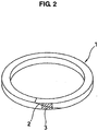
- a seal ring 1 that is provided with a cut portion 2, as shown in Figure 2 , it is possible to identify the cut portion 2 by applying a marking 3 with a white-based color to the cut portion 2 before hand. Such marking 3 can be used to position the cut portion 2.
- the cut portion 2 is utilized as a fitting part when assembling.
- the cut portion 2 is formed into a straight cut or a stepped cut as well as a bias cut shown in Figure 2 .
- the seal ring 1 is made of PTFE including a filler in a dark color
- a PTFE portion is fluffed, as shown in Figure 1 , thereby applying to the cut portion 2 the marking 3 that has a primary white-based color of PTFE.
- the seal ring it is possible in the seal ring to easily identify the cut portion 2 that serves as a fitting part, to identify similar seal rings, or to identify orientation of the seal ring. Also, in the case of applying a marking with a white-based color to an intermediate product for the seal ring 1, a marking work can be done simultaneously to a plurality of them.
- the irradiated and fluffed portion with a white base color is returned to the original color by means of friction, because a fluffed state of the PTFE is returned to the original dense state color. Accordingly, when a marking is applied to a sliding portion, the marking serves as a signal on a product but the marking is abraded away by the above reaction after the product is transformed into a finished article and the finished article is assembled in a sliding portion. In other words, the marking will be good enough to remain effective (not to be abraded away) from a producing step to a assembling step. Even if the marking is worn after assembling, this will not affect a primary function of the finished article.
- a marking is applied to a non-sliding portion of a product, various kinds of characters, signs, figures or the like such as a name of a company, an article code, or the like can be applied to the portion. If the marking is applied to a non-sliding portion of a product, since the marking is not abraded away, it is possible to identify a finished article and not to affect a function of the article.
- the present invention has the following advantages.
- a marking method according to Claim 1 and a product according to Claim 2 it is possible to readily apply a marking with a white-based color to a cut portion of a seal ring, which is made of PTFE. Accordingly, when it is necessary to identify a cut portion of a seal ring, it is possible to easily perform an identifying work.
- the marking method of the present invention it is possible to directly apply a marking to a cut portion of a seal ring without working a surface of PTFE. Consequently, it is possible to form a uniform and distinct marking.
- the marking method of the present invention since the marked portion is not peeled and foreign substances due to peeling are not caused, the marking does not affect a primary function of the marked product. Accordingly, a marking of the present invention can be applied to a sliding portion.
- the marking method of the present invention since it is not required to add a special additive for the purpose of marking, which is unnecessary for a primary function of a product or a finished article, it is possible to omit a work of selecting an additive for every seal ring to be marked or adding an additive to the seal ring. Also, it is possible to avoid generation of contaminants from a product or a finished article.
- the present invention can further obtain the following effects.
Landscapes
- Physics & Mathematics (AREA)
- Optics & Photonics (AREA)
- Thermal Transfer Or Thermal Recording In General (AREA)
- Laser Beam Processing (AREA)
Description
- This invention relates to a marking method and a product marked by the marking method, and more particularly relates to a method for applying a marking to a cut portion of a seal ring by irradiating a laser beam onto the cut portion and a seal ring obtained by the method. Also, the present invention is utilized when identification is required in a technical field for using or producing PTFE (polytetrafluoroethylene).
- Heretofore, it has been required for a marking to be applied to a surface of a resin-molded product in order to identify the product by means of a type or a lot number of an article.
- There are known conventional marking methods for a resin material, such as a method for forming a marking by irradiating a laser beam onto a thermoplastic resin material to make a foamed bulge (Japanese Patent Laid Open No.
62-13287 9-175025 4-42122 2001-113830 61-11771 8-142510 2001-294758 - On the other hand, some conventional methods for applying a marking to PTFE employ a technique of paint coating or stamping. However, the marking method employing the technique of using paint has following problems.
- (1) Since PTFE has repellency against water and oil on its surface due to its material characteristics, it has a poor wet property for paint and thus paint cannot be applied uniformly to PTFE. This results in an uneven or unclear marking.
- (2) Since PTFE has a poor adhesive property on other materials, marking paint will be easily stripped from PTFE. The product thus cannot be identified and the stripped paint will cause foreign substances. Consequently, such marked product will not satisfy a requirement for an essential property of an article.
- (3) In the case of coating PTFE with paint, since a paint layer increases partially a thickness of the PTFE, such marked product will not satisfy a requirement for an essential property of an article.
- (4) It is required for a long period in time to dry a dispersion medium such as water or organic solvent used in paint.
- (5) In the case where a marking surface is not flat (for example, a curved surface, or a polygonal surface), it is impossible to apply printing with paint on that surface.
- (6) Although it is necessary to add a special additive for the purpose of marking, the additive is not necessary for a product in view of an essential property of the product. Accordingly, it is necessary to suitably select an additive to be used in accordance with an application and a function of a product or a finished article. This will require a lot of man-hours for steps of selection and addition. Moreover, as stated above, since the additive is not necessary for a product in view of an essential property of the product, the additive may cause contaminants.
-
US 5 320 789 A discloses a method of irradiating laser light on a surface of a fluorine resin to improve adhesion and wetting properties thereof.JP-H06 228325 - Still other aims and advantages of the invention will in part be obvious and will in part be apparent from the specification.
- To achieve the above aims, the present invention is directed to a method according to
Claim 1. - The invention of
Claim 2 is directed to a product obtained by said method. - The features of the present invention are as follows.
- (1) It is possible in the present invention to apply a marking to PTFE that contains no filler. When the marking method of the present invention is applied to the PTFE, an irradiated portion of the PTFE is altered (to cause fluffing) while a non-irradiated portion of the PTFE is not altered (not to cause fluffing). Although both portions exhibit the same white colors, which are slightly short of identification, the irradiated portion can be distinguished from the non-irradiated portion on account of different degrees of reflection in light between them.
- (2) It is possible in the present invention to apply a marking to PTFE that contains any filler.
- a) In the case where a filler has a color other than a white-based color:
If the marking method of the present invention is applied to PTFE that contains a filler which has a color other than a white-based color, a marking is excellent at identification, since the irradiated portion of the PTFE is altered (to be fluffed) while exhibiting its own white color and exhibits a distinct contrast. - b) In the case where a filler has a white-based color:
The marking method of the present invention can be applied to a filler that has a white-based color. If the marking method of the present invention is applied to PTFE that contains a filler which has a white-based color, a difference between the irradiated portion and the non-irradiated portion is present on account of different degrees of reflection in light,
although the irradiated portion is slightly poor in identification.
- a) In the case where a filler has a color other than a white-based color:
- It is preferable to select a filler from materials such as glass fiber, carbon fiber, glass bead, carbon powder, potassium titanate fiber, alumina powder, bronze powder, silica powder, boron nitride powder, molybdenum disulfide powder, silicon nitride powder, aromatic polyester powder, polyetheretherketone powder, polyimide powder. It should be noted that the filler is not limited to the above materials.
- In the case where a cut portion of a seal ring is made of PTFE, when the cut portion is irradiated by a laser beam, PTFE is fluffed and a surface of the cut portion is covered with PTFE to exhibit its own white-based color. Thus the function of a marking is achieved. It is preferable to set an amount of PTFE that covers the surface of the object in accordance with a hue of a base material (a hue of an object to be marked) to identify the marking.
- The marking method of the present invention does not employ a conventional technique of peeling a paint material, peeling a surface layer, discoloring or color-developing a composition such as a special filler, or foaming a blowing agent but employs marking with a white-based color by means of fluffing. PTFE can be selected in accordance with fluffing regardless of a kind and an amount of a filler. Accordingly, it is possible to select a mixture of PTFE and other resin material or elastomer within a range of composition that the PTFE is fluffed. Also, the marking method of the present invention is advantageous, since no foreign substances are caused during irradiation of a laser beam.
- Principles in conventional marking methods are explained by the following three patterns in
Figures 3A, 3B and 3C . - (1) Peeling of a printed surface (a contrast between an upper layer 52 and a
lower layer 53 is present by peeling an ink or apaint 51 on the upper surface 52 (seeFigure 3A ). - (2) Peeling of a surface layer (a
surface layer 54 is peeled by a laser beam (seeFigure 3B ). - (3) Color development due to chemical change (a
surface 55 is brought into color development by causing a chemical change by means of irradiation of a laser beam (seeFigure 3C ). - The features of the present invention believed to be novel and the elements characteristic of the present invention are set forth with particularity in the appended claims. The figures are for illustration purposes only and are not drawn to scale. The invention itself, however, both as to organization and method of operation, may best be understood by reference to the detailed description which follows taken in conjunction with the accompanying drawings in which:
-
Figure 1 is an enlarged photographical view of a surface of a PTFE composition, which is marked by a marking method similar to that
of the present invention; -
Figure 2 is a perspective view of a seal ring, which is marked by a marking method according to an embodiment of the present invention; and -
Figures 3A, 3B, and 3C are explanatory views, each illustrating a principle of a conventional laser marking method. - Referring to the drawings, embodiments of the present invention will be now explained below.
- A laser beam source to be used in a marking method of the present invention may be, for example, a gas laser such as a CO2 laser, a semiconductor laser, a solid body laser such as a YAG laser, or the like. An amount of a thermal irradiation for marking depends on a degree of identification, although there are some differences among kinds of laser. The marking
will be described below in more detail in connection with a condition of irradiation using a CO2 laser. - A PTFE product, which is used as an object to be marked, is a sheet (20 mm x 20 mm x 2 mm) obtained by pressing and baking a mixture in which 17 parts by weight of carbon fiber having a length of 100 µ m are dispersed in 100 parts by weight of PTFE. The sheet has a black-based color.
-
Figure 1 shows an electron micrograph of a marking applied under a condition of 3.6 W in power and 300 mm/s in marking speed. InFigure 1 , an upper layer shows a portion irradiated by a laser beam while a lower layer shows a non-irradiated portion. The words "to alter PTFE by irradiating a laser beam (to cause fluffing)" described herein means the state of the upper layer shown inFigure 1 . - Next, conditions and results in examples of a marking are shown in Table 1.
Table 1 Marking speed (mm/s) 150 300 400 Power (W) Marking state Surface state of article Marking state Surface state of article Marking state Surface state of article 0.6 × ⊚ × ⊚ × ⊚ 1.2 ○ ○ × ⊚ × ⊚ 2.4 ○ × Δ ○ Δ ○ 3.6 ○ × ○ ○ Δ ○ 4.8 ○ × ○ ○ ○ ○ 6 ○ × ○ ○ ○ ○ 7.2 ○ × ○ Δ ○ ○ 8.4 ○ × ○ × ○ ○ 9.6 ○ × ○ × ○ Δ *Marking state:
○: A marking is as white as can be easily identified.
Δ: A marking can be identified.
× : A marking is difficult to be identified.
*SurFace state of article, i.e.
a degree in which change in surface roughness and thickness of an irradiated portion exerts an influence upon a function of an article in comparison with a non-irradiated portion:
⊚: Excellent (because it is nearly equal to a non-irradiated state).
○ : No influence was exerted.
Δ : There is possibility of any influence.
× : Influence was exerted. - As shown in Table 1, when a marking speed is fixed at 150 (mm/s), a marking exhibits a distinct white-based color at 1.2 W or more of power.
- Further, when a marking speed is fixed at 300 (mm/s), a marking exhibits a distinguishable white-based color with fluffing at about 2 W of power and exhibits a distinct white-based color at 3.6 W or more of power.
- Still further, when a marking speed is fixed at 400 (mm/s), a marking exhibits a distinguishable white-based color with fluffing at about 2 W of power and exhibits a distinct white-based color at 4.8 W or more of power.
- However, since an irradiated portion is subject to change in surface roughness and thickness in comparison with a non-irradiated portion, a surface state of the irradiated portion may exert an influence upon a function of an article. For example, when a CO2 laser, in which a diameter of a laser beam is 14 mm, is used to apply a marking to a seal ring, the seal ring is subject to the following effects.
- (1) Deformation, for example, deterioration of circularity, change of thickness;
- (2) Concave and undulation of surface
- (3) Deterioration of physical properties in a surface layer (mechanical strength, elongation, energy of rupture, abrasion resistance and the like)
- (4) Abnormality in frictional phenomenon upon sliding.
- The above effects may cause a possibility of deterioration of a leak-proof performance. Accordingly, even if a marking is in a distinguishable state, it may be not suitable to an article.
- In view of the above evaluation on Table 1, it will be preferable to apply a marking to an object to be marked by increasing a power of laser and a marking speed in order to obtain an excellent marking without affecting a primary function of an article.
- Accordingly, it will be preferable from Table 1 that a marking condition
is 1.2 W of power at 150 mm/s of a marking speed, 3.6 to 6 W of power at 300 mm/s of a marking speed, and 4.8 to 8.4 W of power at 400 mm/s of a marking speed. - It is possible to control a marking state (contrast) by regulating a power of an irradiating laser beam and a marking speed. That is, if the power is lowered and the marking speed is increased, the marking state (contrast) is attenuated while if the power is raised and the marking speed is decreased, the marking state (contrast) is deepened.
- In the case of applying a laser beam to an object to be marked which is made of PTFE, a surface temperature on the object upon irradiation of the laser beam will be estimated by the following equation:

- Tp: surface temperature (°C)
- β: absorption factor of laser
- F: power density (W/cm2)
- λ: coefficient of thermal conductivity (cal/cm °C s)
- c: specific heat (cal/°C g)
- ρ: density (g/cm3)
- t: irradiating period in time (s)
- A product, which is made of PTFE,
- A marking method of the present invention can be applied to an intermediate product or an end product of the above seal ring. For example, an intermediate product for the seal ring is a product before being cut while an end product for the seal ring is a product after being cut.
- In a
seal ring 1 that is provided with acut portion 2, as shown inFigure 2 , it is possible to identify thecut portion 2 by applying amarking 3 with a white-based color to thecut portion 2 before hand.Such marking 3 can be used to position thecut portion 2. Thecut portion 2 is utilized as a fitting part when assembling. Thecut portion 2 is formed into a straight cut or a stepped cut as well as a bias cut shown inFigure 2 . - In the case where the
seal ring 1 is made of PTFE including a filler in a dark color, when an outer peripheral position on thecut portion 2 is irradiated by a laser beam in accordance with the marking method of the present invention, a PTFE portion is fluffed, as shown inFigure 1 , thereby applying to thecut portion 2 themarking 3 that has a primary white-based color of PTFE. - Accordingly, it is possible in the seal ring to easily identify the
cut portion 2 that serves as a fitting part, to identify similar seal rings, or to identify orientation of the seal ring. Also, in the case of applying a marking with a white-based color to an intermediate product for theseal ring 1, a marking work can be done simultaneously to a plurality of them. - Although the
marking 3 is depicted in a simple band-like pattern inFigure 2 , various kinds of characters, signs, figures or the like such as a name of a company, an article code, or the like can be marked. - The irradiated and fluffed portion with a white base color is returned to the original color by means of friction, because a fluffed state of the PTFE is returned to the original dense state color. Accordingly, when a marking is applied to a sliding portion, the marking serves as a signal on a product but the marking is abraded away by the above reaction after the product is transformed into a finished article and the finished article is assembled in a sliding portion. In other words,
the marking will be good enough to remain effective (not to be abraded away) from a producing step to a assembling step. Even if the marking is worn after assembling, this will not affect a primary function of the finished article. If a marking is applied to a non-sliding portion of a product, various kinds of characters, signs, figures or the like such as a name of a company, an article code, or the like can be applied to the portion. If the marking is applied to a non-sliding portion of a product, since the marking is not abraded away, it is possible to identify a finished article and not to affect a function of the article. - The present invention has the following advantages.
- In a marking method according to
Claim 1 and a product according toClaim 2, it is possible to readily apply a marking with a white-based color to a cut portion of a seal ring, which is made of PTFE. Accordingly, when it is necessary to identify a cut portion of a seal ring, it is possible to easily perform an identifying work. - According to the marking method of the present invention, it is possible to directly apply a marking to a cut portion of a seal ring without working a surface of PTFE.
Consequently, it is possible to form a uniform and distinct marking. - According to the marking method of the present invention, since the marked portion is not peeled and foreign substances due to peeling are not caused, the marking does not affect a primary function of the marked product. Accordingly, a marking of the present invention can be applied to a sliding portion.
- Since it is not necessary to dry a marked portion in the present invention, a period in time required for marking can be shortened.
- In the present invention, when a cut portion of a seal ring is irradiated by a laser beam, since an irradiated portion of PTFE is altered (fluffed) and the cut portion exhibits a white-based color that is a primary color of PTFE, thereby the function of a marking being achieved, it is possible to apply a marking to any surface on the cut portion that is not flat.
- In the marking method of the present invention, since it is not required to add a special additive for the purpose of marking, which is unnecessary for a primary function of a product or a finished article, it is possible to omit a work of selecting an additive for every seal ring to be marked or adding an additive to the seal ring. Also, it is possible to avoid generation of contaminants from a product or a finished article.
- The present invention can further obtain the following effects.
- (1) It is possible to easily control a contrast with a white-based color by regulating a power and an irradiating speed of a laser apparatus.
- (2) It is possible to apply a marking with small characters, since it is possible to readily carry out a control of a marking size.
- (3) In comparison with a conventional technique, the present invention is not subject to limitation of peeling of paint, peeling of a surface layer, discolor or color development of a composition such as a special filler or the like, and mixing of a special forming agent, PTFE is not subject to limitation of composition.
- While the present invention has been particularly described, in conjunction with a specific preferred embodiment, it is evident that many alternatives, modifications, and variations will be apparent to those skilled in the art in light of the foregoing description.
Claims (2)
- A method for applying a marking (3) to a cut portion (2) of a seal ring (1) by irradiating a laser beam onto said cut portion (2), comprising the steps of:preparing a seal ring (1) that is made of a material of PTFE and is provided with a cut portion (2);irradiating a laser beam onto said cut portion (2) to alter the state of only an irradiated surface of the PTFE; andforming a marking (3) with a white-based color on the irradiated surface of the PTFE so that the irradiated surface exhibits a color tone different from that of a non-irradiated surface of the PTFE.
- A seal ring (2) that is made of a material of PTFE and is provided with a cut portion (2), wherein said cut portion (2) is marked by the method according to claim 1, thereby forming a marking (3) with a white-based color on the irradiated surface of the PTFE so that the irradiated surface exhibits a color tone different from that of a non-irradiated surface of the PTFE.
Applications Claiming Priority (3)
| Application Number | Priority Date | Filing Date | Title |
|---|---|---|---|
| JP2002288230 | 2002-10-01 | ||
| JP2002288230 | 2002-10-01 | ||
| PCT/JP2003/012617 WO2004030920A1 (en) | 2002-10-01 | 2003-10-01 | Marking method and marked molding |
Publications (3)
| Publication Number | Publication Date |
|---|---|
| EP1475238A1 EP1475238A1 (en) | 2004-11-10 |
| EP1475238A4 EP1475238A4 (en) | 2005-03-09 |
| EP1475238B1 true EP1475238B1 (en) | 2018-07-25 |
Family
ID=32063650
Family Applications (1)
| Application Number | Title | Priority Date | Filing Date |
|---|---|---|---|
| EP03758704.5A Expired - Lifetime EP1475238B1 (en) | 2002-10-01 | 2003-10-01 | Marking method and marked molding |
Country Status (6)
| Country | Link |
|---|---|
| US (1) | US20050145131A1 (en) |
| EP (1) | EP1475238B1 (en) |
| JP (1) | JP3915930B2 (en) |
| CN (1) | CN100343075C (en) |
| AU (1) | AU2003275538A1 (en) |
| WO (1) | WO2004030920A1 (en) |
Families Citing this family (7)
| Publication number | Priority date | Publication date | Assignee | Title |
|---|---|---|---|---|
| JP2007306944A (en) * | 2005-01-21 | 2007-11-29 | Olympus Corp | Endoscope, medical appliance for endoscope, and method for display thereof |
| JP4715396B2 (en) * | 2005-08-30 | 2011-07-06 | 株式会社デンソー | Fluid control valve |
| US7963502B2 (en) * | 2006-08-25 | 2011-06-21 | Fisher Controls International Llc | Low friction live-loaded packing |
| EP2096580B1 (en) * | 2008-02-29 | 2011-12-21 | Carl Freudenberg KG | Product marking |
| EP2128802A1 (en) | 2008-05-29 | 2009-12-02 | Carl Freudenberg KG | Component provided with machine readable identification |
| EP2792499A1 (en) * | 2013-04-19 | 2014-10-22 | Siemens Aktiengesellschaft | Method for labelling a component |
| CN103745784A (en) * | 2014-01-09 | 2014-04-23 | 深圳琦富瑞电子有限公司 | Manufacturing and character printing method for Teflon electric wires |
Citations (2)
| Publication number | Priority date | Publication date | Assignee | Title |
|---|---|---|---|---|
| US4645215A (en) * | 1985-01-15 | 1987-02-24 | Firma Carl Freudenberg | Shaft and radially sealing ring with cold flexed seal disk and a method of its use for sealing the crankshaft of a two-cycle engine |
| JPH06228325A (en) * | 1993-02-03 | 1994-08-16 | Sakagami Seisakusho:Kk | Coloration of tetrafluoroethylene resin molding |
Family Cites Families (15)
| Publication number | Priority date | Publication date | Assignee | Title |
|---|---|---|---|---|
| DE3044722C2 (en) * | 1980-11-27 | 1982-11-25 | Siemens AG, 1000 Berlin und 8000 München | Process for the production of identical plastic parts provided with different symbols, in particular plastic device buttons, by injection molding |
| AU597240B2 (en) * | 1985-02-05 | 1990-05-31 | Ciba-Geigy Ag | Laser marking of pigmented systems |
| CA2046881A1 (en) * | 1989-01-25 | 1990-07-26 | Hans E. Lunk | Fluoropolymer compositions |
| EP0413664B1 (en) * | 1989-08-18 | 1995-03-22 | Ciba-Geigy Ag | Laser-marking of plastic objects in any form by means of special effects |
| US5320789A (en) * | 1991-11-06 | 1994-06-14 | Japan Atomic Energy Research Institute | Surface modification of fluorine resin with laser light |
| JPH07196880A (en) * | 1993-12-28 | 1995-08-01 | Akishima Kagaku Kogyo Kk | Fluorine-containing resin composition with improved processability |
| US5560845A (en) * | 1994-02-28 | 1996-10-01 | E. I. Du Pont De Nemours And Company | Laser marking of fluoropolymer composition |
| JP3024495B2 (en) * | 1994-10-21 | 2000-03-21 | ジェイエスアール株式会社 | Resin composition for laser marking |
| JPH08215865A (en) * | 1995-02-16 | 1996-08-27 | Sumitomo Electric Ind Ltd | Fluororesin coating and method for producing the same |
| FR2732030B1 (en) * | 1995-03-20 | 1997-04-30 | Plastic Omnium Cie | COATING METAL BASED ON POLYTETRAFLUOROETHYLENE SUITABLE FOR LASER MARKING. |
| NL1001784C2 (en) * | 1995-11-30 | 1997-06-04 | Dsm Nv | Method of manufacturing an object with colored marking. |
| US6075223A (en) * | 1997-09-08 | 2000-06-13 | Thermark, Llc | High contrast surface marking |
| US6852948B1 (en) * | 1997-09-08 | 2005-02-08 | Thermark, Llc | High contrast surface marking using irradiation of electrostatically applied marking materials |
| JPH11180099A (en) * | 1997-12-18 | 1999-07-06 | Matsushita Electric Ind Co Ltd | Marking method and resin molding with mark |
| JP2000289128A (en) * | 1999-04-09 | 2000-10-17 | Nissei Electric Co Ltd | Marking tube molded article and method for producing the same |
-
2003
- 2003-10-01 EP EP03758704.5A patent/EP1475238B1/en not_active Expired - Lifetime
- 2003-10-01 WO PCT/JP2003/012617 patent/WO2004030920A1/en not_active Ceased
- 2003-10-01 CN CNB038012758A patent/CN100343075C/en not_active Expired - Lifetime
- 2003-10-01 AU AU2003275538A patent/AU2003275538A1/en not_active Abandoned
- 2003-10-01 JP JP2004541267A patent/JP3915930B2/en not_active Expired - Lifetime
- 2003-10-01 US US10/502,098 patent/US20050145131A1/en not_active Abandoned
Patent Citations (2)
| Publication number | Priority date | Publication date | Assignee | Title |
|---|---|---|---|---|
| US4645215A (en) * | 1985-01-15 | 1987-02-24 | Firma Carl Freudenberg | Shaft and radially sealing ring with cold flexed seal disk and a method of its use for sealing the crankshaft of a two-cycle engine |
| JPH06228325A (en) * | 1993-02-03 | 1994-08-16 | Sakagami Seisakusho:Kk | Coloration of tetrafluoroethylene resin molding |
Also Published As
| Publication number | Publication date |
|---|---|
| JPWO2004030920A1 (en) | 2006-02-02 |
| JP3915930B2 (en) | 2007-05-16 |
| WO2004030920A1 (en) | 2004-04-15 |
| CN100343075C (en) | 2007-10-17 |
| AU2003275538A1 (en) | 2004-04-23 |
| EP1475238A4 (en) | 2005-03-09 |
| US20050145131A1 (en) | 2005-07-07 |
| EP1475238A1 (en) | 2004-11-10 |
| CN1568263A (en) | 2005-01-19 |
Similar Documents
| Publication | Publication Date | Title |
|---|---|---|
| EP3749527B1 (en) | Direct thermal recording media based on selective change of state | |
| US6964226B2 (en) | Method of transferring a membrane image to an article in a membrane image transfer printing process | |
| CA1295462C (en) | Method of making a gasket or seal | |
| EP0909655B1 (en) | Method for forming pad character in push button switch and method for manufacturing cover member for push button switch | |
| JPH0968924A (en) | How to use labels to mark rubber components, especially tires | |
| JPH10312726A (en) | Pressing member for illuminated push button switch, method for manufacturing the same, and illuminated push button switch | |
| CN101142089A (en) | Two-color molded article for laser marking and laser marking method | |
| EP1475238A1 (en) | Marking method and marked molding | |
| KR20030031862A (en) | Non-contacting type rewrite thermal label and its using method | |
| AU9309398A (en) | Laser marking method | |
| KR20120055606A (en) | Method for manufacturing an injection-molded object | |
| RU2235647C2 (en) | Thermal mass transfer printing methods | |
| US20220145135A1 (en) | Method for Ablating a Label With a Laser | |
| US10513139B2 (en) | Flexographic printing plate, method for manufacturing flexographic printing plate, and flexographic printing plate precursor | |
| EP0732358B1 (en) | Light-coloured urea resin-based thermosetting moulding powder or mass and relative laser-markable products | |
| TWI907870B (en) | Keycap structure and manufacturing method thereof | |
| US20020123002A1 (en) | Method for decorating molding | |
| JP2008281618A (en) | Planarizing sheet and color filter manufacturing method using the same | |
| JP3593657B2 (en) | Belt with mark and method for forming mark on belt | |
| JP4483017B2 (en) | Wiring equipment switch member | |
| CN115179619A (en) | Composite material pressing pad and marking operation process and application thereof | |
| JP2807684B2 (en) | Cover member for illuminated pushbutton switch | |
| CN223167381U (en) | Character display structure and key structure with the same | |
| JPH032667B2 (en) | ||
| GB2388817A (en) | A porous resin stamp containing phthalocyanine pigments, and a method of manufacturing the same |
Legal Events
| Date | Code | Title | Description |
|---|---|---|---|
| PUAI | Public reference made under article 153(3) epc to a published international application that has entered the european phase |
Free format text: ORIGINAL CODE: 0009012 |
|
| 17P | Request for examination filed |
Effective date: 20040914 |
|
| AK | Designated contracting states |
Kind code of ref document: A1 Designated state(s): AT BE BG CH CY CZ DE DK EE ES FI FR GB GR HU IE IT LI LU MC NL PT RO SE SI SK TR |
|
| AX | Request for extension of the european patent |
Extension state: AL LT LV MK |
|
| A4 | Supplementary search report drawn up and despatched |
Effective date: 20050126 |
|
| DAX | Request for extension of the european patent (deleted) | ||
| RBV | Designated contracting states (corrected) |
Designated state(s): DE FR GB |
|
| 17Q | First examination report despatched |
Effective date: 20170731 |
|
| R17C | First examination report despatched (corrected) |
Effective date: 20170731 |
|
| GRAP | Despatch of communication of intention to grant a patent |
Free format text: ORIGINAL CODE: EPIDOSNIGR1 |
|
| INTG | Intention to grant announced |
Effective date: 20180206 |
|
| GRAS | Grant fee paid |
Free format text: ORIGINAL CODE: EPIDOSNIGR3 |
|
| GRAA | (expected) grant |
Free format text: ORIGINAL CODE: 0009210 |
|
| AK | Designated contracting states |
Kind code of ref document: B1 Designated state(s): DE FR GB |
|
| REG | Reference to a national code |
Ref country code: GB Ref legal event code: FG4D |
|
| REG | Reference to a national code |
Ref country code: DE Ref legal event code: R096 Ref document number: 60351351 Country of ref document: DE |
|
| REG | Reference to a national code |
Ref country code: FR Ref legal event code: PLFP Year of fee payment: 16 |
|
| RIC2 | Information provided on ipc code assigned after grant |
Ipc: B23K 26/00 20140101ALI20040420BHEP Ipc: B41M 5/26 20060101AFI20040420BHEP Ipc: F02F 5/00 20060101ALI20040420BHEP |
|
| REG | Reference to a national code |
Ref country code: DE Ref legal event code: R097 Ref document number: 60351351 Country of ref document: DE |
|
| PLBE | No opposition filed within time limit |
Free format text: ORIGINAL CODE: 0009261 |
|
| STAA | Information on the status of an ep patent application or granted ep patent |
Free format text: STATUS: NO OPPOSITION FILED WITHIN TIME LIMIT |
|
| 26N | No opposition filed |
Effective date: 20190426 |
|
| PGFP | Annual fee paid to national office [announced via postgrant information from national office to epo] |
Ref country code: GB Payment date: 20220901 Year of fee payment: 20 |
|
| PGFP | Annual fee paid to national office [announced via postgrant information from national office to epo] |
Ref country code: FR Payment date: 20220908 Year of fee payment: 20 |
|
| PGFP | Annual fee paid to national office [announced via postgrant information from national office to epo] |
Ref country code: DE Payment date: 20220621 Year of fee payment: 20 |
|
| REG | Reference to a national code |
Ref country code: DE Ref legal event code: R071 Ref document number: 60351351 Country of ref document: DE |
|
| REG | Reference to a national code |
Ref country code: GB Ref legal event code: PE20 Expiry date: 20230930 |
|
| PG25 | Lapsed in a contracting state [announced via postgrant information from national office to epo] |
Ref country code: GB Free format text: LAPSE BECAUSE OF EXPIRATION OF PROTECTION Effective date: 20230930 |