EP1474594B1 - Gegenkolben verwendender verbrennungsmotor - Google Patents
Gegenkolben verwendender verbrennungsmotor Download PDFInfo
- Publication number
- EP1474594B1 EP1474594B1 EP02768951A EP02768951A EP1474594B1 EP 1474594 B1 EP1474594 B1 EP 1474594B1 EP 02768951 A EP02768951 A EP 02768951A EP 02768951 A EP02768951 A EP 02768951A EP 1474594 B1 EP1474594 B1 EP 1474594B1
- Authority
- EP
- European Patent Office
- Prior art keywords
- combustion
- piston
- cylinder
- combustion chamber
- pistons
- Prior art date
- Legal status (The legal status is an assumption and is not a legal conclusion. Google has not performed a legal analysis and makes no representation as to the accuracy of the status listed.)
- Expired - Lifetime
Links
- 238000002485 combustion reaction Methods 0.000 title claims description 103
- 239000000446 fuel Substances 0.000 claims description 15
- RYGMFSIKBFXOCR-UHFFFAOYSA-N Copper Chemical compound [Cu] RYGMFSIKBFXOCR-UHFFFAOYSA-N 0.000 claims description 5
- 229910052802 copper Inorganic materials 0.000 claims description 5
- 239000010949 copper Substances 0.000 claims description 5
- 229910001220 stainless steel Inorganic materials 0.000 claims description 3
- 239000010935 stainless steel Substances 0.000 claims description 3
- 239000000203 mixture Substances 0.000 claims description 2
- 230000013011 mating Effects 0.000 claims 1
- 239000003570 air Substances 0.000 description 73
- 238000007906 compression Methods 0.000 description 24
- 230000006835 compression Effects 0.000 description 24
- 239000000463 material Substances 0.000 description 14
- 239000007789 gas Substances 0.000 description 7
- 230000002706 hydrostatic effect Effects 0.000 description 7
- 230000000712 assembly Effects 0.000 description 5
- 238000000429 assembly Methods 0.000 description 5
- 230000000694 effects Effects 0.000 description 5
- 238000007789 sealing Methods 0.000 description 5
- 239000012080 ambient air Substances 0.000 description 4
- 238000004891 communication Methods 0.000 description 4
- 229910000831 Steel Inorganic materials 0.000 description 3
- 230000001133 acceleration Effects 0.000 description 3
- 238000010276 construction Methods 0.000 description 3
- 238000001816 cooling Methods 0.000 description 3
- 238000011068 loading method Methods 0.000 description 3
- 239000000314 lubricant Substances 0.000 description 3
- 238000005461 lubrication Methods 0.000 description 3
- 229910052751 metal Inorganic materials 0.000 description 3
- 239000002184 metal Substances 0.000 description 3
- 238000000034 method Methods 0.000 description 3
- 230000036316 preload Effects 0.000 description 3
- 238000010926 purge Methods 0.000 description 3
- 239000010959 steel Substances 0.000 description 3
- XEEYBQQBJWHFJM-UHFFFAOYSA-N Iron Chemical compound [Fe] XEEYBQQBJWHFJM-UHFFFAOYSA-N 0.000 description 2
- 229910052782 aluminium Inorganic materials 0.000 description 2
- XAGFODPZIPBFFR-UHFFFAOYSA-N aluminium Chemical compound [Al] XAGFODPZIPBFFR-UHFFFAOYSA-N 0.000 description 2
- 238000005452 bending Methods 0.000 description 2
- 230000007423 decrease Effects 0.000 description 2
- 230000003247 decreasing effect Effects 0.000 description 2
- 239000012530 fluid Substances 0.000 description 2
- 238000005339 levitation Methods 0.000 description 2
- 238000004519 manufacturing process Methods 0.000 description 2
- 230000035882 stress Effects 0.000 description 2
- 238000011144 upstream manufacturing Methods 0.000 description 2
- 235000014676 Phragmites communis Nutrition 0.000 description 1
- 208000034809 Product contamination Diseases 0.000 description 1
- 230000009471 action Effects 0.000 description 1
- 239000004411 aluminium Substances 0.000 description 1
- 238000005219 brazing Methods 0.000 description 1
- 230000015556 catabolic process Effects 0.000 description 1
- 230000008859 change Effects 0.000 description 1
- 238000006243 chemical reaction Methods 0.000 description 1
- 239000011248 coating agent Substances 0.000 description 1
- 238000000576 coating method Methods 0.000 description 1
- 230000000052 comparative effect Effects 0.000 description 1
- 239000002131 composite material Substances 0.000 description 1
- 239000002826 coolant Substances 0.000 description 1
- 230000000994 depressogenic effect Effects 0.000 description 1
- 230000009977 dual effect Effects 0.000 description 1
- 238000004880 explosion Methods 0.000 description 1
- 230000009969 flowable effect Effects 0.000 description 1
- 238000010438 heat treatment Methods 0.000 description 1
- 238000002347 injection Methods 0.000 description 1
- 239000007924 injection Substances 0.000 description 1
- 238000009434 installation Methods 0.000 description 1
- 230000003993 interaction Effects 0.000 description 1
- 229910052742 iron Inorganic materials 0.000 description 1
- 239000007788 liquid Substances 0.000 description 1
- 230000014759 maintenance of location Effects 0.000 description 1
- 230000003071 parasitic effect Effects 0.000 description 1
- 230000008569 process Effects 0.000 description 1
- 239000012858 resilient material Substances 0.000 description 1
- 230000004044 response Effects 0.000 description 1
- 238000005096 rolling process Methods 0.000 description 1
- 238000010008 shearing Methods 0.000 description 1
- 229910000679 solder Inorganic materials 0.000 description 1
- 239000007787 solid Substances 0.000 description 1
- 230000008646 thermal stress Effects 0.000 description 1
- 230000007704 transition Effects 0.000 description 1
- XLYOFNOQVPJJNP-UHFFFAOYSA-N water Substances O XLYOFNOQVPJJNP-UHFFFAOYSA-N 0.000 description 1
- 230000003313 weakening effect Effects 0.000 description 1
Images


Classifications
-
- F—MECHANICAL ENGINEERING; LIGHTING; HEATING; WEAPONS; BLASTING
- F01—MACHINES OR ENGINES IN GENERAL; ENGINE PLANTS IN GENERAL; STEAM ENGINES
- F01B—MACHINES OR ENGINES, IN GENERAL OR OF POSITIVE-DISPLACEMENT TYPE, e.g. STEAM ENGINES
- F01B3/00—Reciprocating-piston machines or engines with cylinder axes coaxial with, or parallel or inclined to, main shaft axis
- F01B3/0002—Reciprocating-piston machines or engines with cylinder axes coaxial with, or parallel or inclined to, main shaft axis having stationary cylinders
- F01B3/0017—Component parts, details, e.g. sealings, lubrication
- F01B3/002—Cylinders
-
- F—MECHANICAL ENGINEERING; LIGHTING; HEATING; WEAPONS; BLASTING
- F02—COMBUSTION ENGINES; HOT-GAS OR COMBUSTION-PRODUCT ENGINE PLANTS
- F02B—INTERNAL-COMBUSTION PISTON ENGINES; COMBUSTION ENGINES IN GENERAL
- F02B75/00—Other engines
- F02B75/26—Engines with cylinder axes coaxial with, or parallel or inclined to, main-shaft axis; Engines with cylinder axes arranged substantially tangentially to a circle centred on main-shaft axis
-
- F—MECHANICAL ENGINEERING; LIGHTING; HEATING; WEAPONS; BLASTING
- F02—COMBUSTION ENGINES; HOT-GAS OR COMBUSTION-PRODUCT ENGINE PLANTS
- F02B—INTERNAL-COMBUSTION PISTON ENGINES; COMBUSTION ENGINES IN GENERAL
- F02B75/00—Other engines
- F02B75/28—Engines with two or more pistons reciprocating within same cylinder or within essentially coaxial cylinders
-
- F—MECHANICAL ENGINEERING; LIGHTING; HEATING; WEAPONS; BLASTING
- F02—COMBUSTION ENGINES; HOT-GAS OR COMBUSTION-PRODUCT ENGINE PLANTS
- F02F—CYLINDERS, PISTONS OR CASINGS, FOR COMBUSTION ENGINES; ARRANGEMENTS OF SEALINGS IN COMBUSTION ENGINES
- F02F1/00—Cylinders; Cylinder heads
-
- F—MECHANICAL ENGINEERING; LIGHTING; HEATING; WEAPONS; BLASTING
- F05—INDEXING SCHEMES RELATING TO ENGINES OR PUMPS IN VARIOUS SUBCLASSES OF CLASSES F01-F04
- F05C—INDEXING SCHEME RELATING TO MATERIALS, MATERIAL PROPERTIES OR MATERIAL CHARACTERISTICS FOR MACHINES, ENGINES OR PUMPS OTHER THAN NON-POSITIVE-DISPLACEMENT MACHINES OR ENGINES
- F05C2251/00—Material properties
- F05C2251/04—Thermal properties
- F05C2251/042—Expansivity
- F05C2251/046—Expansivity dissimilar
-
- F—MECHANICAL ENGINEERING; LIGHTING; HEATING; WEAPONS; BLASTING
- F05—INDEXING SCHEMES RELATING TO ENGINES OR PUMPS IN VARIOUS SUBCLASSES OF CLASSES F01-F04
- F05C—INDEXING SCHEME RELATING TO MATERIALS, MATERIAL PROPERTIES OR MATERIAL CHARACTERISTICS FOR MACHINES, ENGINES OR PUMPS OTHER THAN NON-POSITIVE-DISPLACEMENT MACHINES OR ENGINES
- F05C2251/00—Material properties
- F05C2251/04—Thermal properties
- F05C2251/048—Heat transfer
Definitions
- This invention relates to reciprocating internal combustion engines, and particularly to a combustion cylinder for an internal combustion engine.
- Disclosed herein is an advanced version of an engine that eliminates side loadings, utilizes thermally controlled power cylinders, opposed intake and exhaust pistons, piston rings that are cooled and hydrostatically lubricated by air, and incorporates a high temperature cylinder wall which reduces engine emissions and increases engine performance.
- diesel, gas and steam engines of the reciprocating type typically convert the linear piston motion into rotary motion by utilizing piston (s), connecting rod, and crankshaft.
- This conversion process obviously creates a substantial piston side load which requires oil lubrication to control friction and wear of the piston skirt and cylinder and a substantial and heavy engine case.
- the cylinder wall and piston side walls and rings generally are maintained at a temperature that is below a maximum of 177°C (350 degrees Fahrenheit).
- these engines must incorporate a cooling system that serves to reject at least 25 percent of the total heat energy which is dissipated into the ambient air which energy would otherwise provide shaft horsepower.
- an engine which, unlike what is shown in the prior art, floats the piston in the cylinder with a cushion of air by absorbing the side loads that would otherwise load the pistons at locations remote from the piston.
- Unique to the engine is the use of air feed tubes made from a compliant material that keep the piston ring concentric to the piston and supply air to the integral piston ring depressions to hydrostatically compress the piston ring relative to the cylinder and continuously float the piston and piston ring on pockets of pressurized air.
- the engine also uses a unique bearing pack connected to a four bar linkage arrangement and cam to transmit power and reduce side loads to the piston.
- the engine also uses a unique jumper system for the purpose of storing base compression air which is pressurized for use in purging the combustion chamber of combusted materials and supply preheated air to the combustion chamber prior to combustion.
- an engine is provided that has a unique power cylinder that distributes heat of combustion along the length of the cylinder to allow higher operating temperatures in the power cylinder.
- One of the inventors of the present invention is the inventor of United States Patent Number 5,551,383 .
- This patent discloses the use of an air bearing system that relies upon pressurized air provided by a base compression cylinder that is co-annular to the power cylinder.
- the 383 patent also employs a four bar linkage system, but the disclosed system is rather complex to replicate in a working engine and doesn't provide the benefits of the unique four bar system disclosed herein.
- the '383 patent also doesn't employ a power cylinder that manages heat to allow higher temperatures to be used in the combustion chamber and power cylinder as does the engine of embodiments of the present invention.
- Other improvements are disclosed and claimed in the present application that are not taught or suggested in the '383 patent.
- U.S. Pat. No. 5,375,567 granted to A. Lowi, Jr. on Dec. 27, 1994 discloses a two-stroke-cycle engine that requires no cooling and utilizes twin double-harmonic cams that claim to balance reciprocating and rotary motion at all loads and speeds so as to obviate all side loads.
- the present invention makes no claim to the ability of operating without lubrication, although the engine disclosed herein does not require oil as a lubricant for the pistons as is the case for most piston engines it does use air as a lubricant. It also utilizes a four bar linkage system to reduce side loads. Still further, the engine may employ unique seals to seal and absorb the slight side loads that may be encountered by the pistons of the engine.
- the present invention provides a combustion cylinder in accordance with claim 1.
- the present invention extends to an internal combustion engine in accordance with claim 11.
- the present invention may provide an improved internal combustion engine that has a low weight to power ratio, low emissions and low fuel consumption.
- the engine provides numerous improvements over known internal combustion engines.
- an internal combustion engine having a housing enclosing at least one cylinder with opposed pistons mounted for reciprocation within the cylinder.
- Opposed power cams are mounted upon a power output shaft. Each of the power cams are operatively connected to a respective one of the opposed pistons.
- End plates are mounted to the housing and divide the housing into a center section and end sections. At least one cylinder with opposed pistons mounted for reciprocation within the cylinder is mounted within the center section and one each of the opposed power cams is mounted within a respective one of the end sections.
- the opposed pistons have connecting rods operatively interconnecting the pistons to the cams.
- the end plates have openings for reciprocal receipt of the connection rods.
- the power cylinder of the present invention is uniquely designed to distribute heat along the length of the power cylinder to avoid tapering of the cylinder.
- the power cylinder has a first member defined by a first hollow tube having a predetermined length.
- the first hollow tube is adapted to receive at least one piston for reciprocal movement within the first hollow tube.
- the first hollow tube defines a combustion chamber wherein a fuel and air mixture can be introduced compressed and ignited.
- This first hollow tube has a high thermal expansion coefficient and low conductivity.
- a second member is mounted adjacent the first member.
- the second member has a high thermal expansion coefficient and high conductivity.
- a third member is positioned about the first hollow tube adjacent the combustion chamber of the first hollow tube.
- the third member has a low thermal expansion coefficient and low conductivity.
- the first, second and third members interact to reduce tapering of the first member by initially containing through the third member heat within the combustion chamber and reducing expansion of the combustion chamber and thereafter distributing heat developed in the combustion chamber along the first member by directing the heat along the second member to maintain a generally uniform temperature along the length of the first member.
- the present invention provides an engine that uses a bearing pack that transfers the power generated by the combustion process to a pair of power cams.
- the bearing pack has a housing, the housing has a top surface and opposed legs extending from the top surface. The legs have facing inner surfaces and outer surfaces.
- a pair of axles extend out of the facing inner surfaces and a pair of pins extending out of the outer surfaces, the axles and pins are coaxial.
- a four bar linkage assembly is connect to the pins and guide wheels are connected to the axles.
- the guide wheels have a first wheel and a second wheel, the first wheel having a larger diameter than the second wheel.
- the opposed cams have opposed spaced apart tracks. The first wheel engages one of the tracks and the second wheel engages the other of the tracks.
- the pistons may be uniquely designed to include facing combustion surfaces with outer perimeters, the outer perimeters of the combustion surfaces each having a profiled surface, the profiled surfaces mate to form a combustion chamber between the piston combustion surfaces. This allows the combustion surface to be generally closed to reduce heat loss from the combustion chamber during combustion.
- an engine incorporating a combustion cylinder of the present invention as described herein is configured with four (4) cylinders and eight (8) pistons and each paired diametrically opposed piston sets are compressing and expanding axi-symmetrically, so as to minimize or eliminate unbalance or out of plane loads at any time during the engines operating envelope for providing a relatively vibration free engine. Since each piston set "fires" twice per output shaft revolution, it produces twice the torque at half the shaft RPM. While this invention is described in the preferred embodiment to include specific parameters, it will be appreciated by one skilled in this art that other parameters including the number of pistons and attendant cylinders could be used without departing from the scope of this invention. It will be appreciated that two opposing pistons in a single cylinder will constitute the minimum number of pistons and cylinders, it will also be appreciated that more or less than four (4) cylinders and eight (8) pistons could be used.
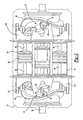
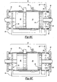
- FIG. 1 is a perspective view of the engine generally indicated by reference numeral 10 which is comprised of a modular cylindrical engine outer case assembly2 surrounding the rotary shaft 14 for rotation about the engine's axis A.
- Shaft 14 extends outwardly from the fore end 16 and the aft end 18.
- an inlet manifold 20 and exhaust pipes 22 which are in communication with the intake pistons and exhaust pistons.
- Inlet conduits 24 connect the intake pistons with the manifold 20.
- the exhaust pipes are directly connected to ports adjacent the exhaust pistons.
- the inlets port 80 disposed in the inlet manifold 20, which may include a suitable filter, leads fresh ambient air into the piston cylinders.
- the exhaust ports disposed adjacent the exhaust pipes 22 discharge the spent combusted products to ambient.
- Fuel is admitted to the cylinders through the fuel nozzle injectors 30 which is fed fuel under pressure through a fuel line, which is not shown.
- Fuel from a fuel reservoir is pressurized in a well known manner from suitable injector pump (s).
- the accessories would be powered by the portion of rotary shaft 14 that extends from the fore end 16 and the power for driving the load would be extracted from the shaft extending from the aft end 18. This is, of course, optional as the power for either the accessories or load may be extracted at either end of rotary shaft 14.
- the load that the engine drives would include without limitation, passenger cars, land vehicles, aircraft and water vehicle propellers, auxiliary power units, generators, earth moving vehicles and the like.
- the power cylinder assembly 36 supports (8) pistons, namely four (4) intake pistons 38 opposing (4) exhaust pistons 40.
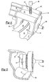
- Rotary shaft 14 connects to and is rotated by the opposing power cams 46 and 48 ( FIGS. 2, 3 ).
- the cams are made of steel and aluminum, but other materials could also be used.
- the cams 46 and 48 are located concentrically and axially within the engine case 12. Power cams 48 and 46 respectively are driven by the intake pistons 38 and exhaust pistons 40 respectively via the connecting rods 58 and 56, that are operatively connected to respective bearing packs 60.
- the bearing pack 60 includes a housing 62 which is generally U-shaped having side walls 64 and 66, legs 65 and a top 68. In the disclosed embodiment, the top 68 and legs 65 are one piece.
- the connecting rods 56 and 58 are connected to a respective bearing pack 60 by a machine bolt 67 passing through the top 68 into a threaded nut 69 in rods 56 and 58.
- the spring factor would be determined by the ratio of the spring rate of the stack of the bolt as follows: K S K B > 4 A S ⁇ E S L S A B ⁇ E B L B > 4 1
- the side walls 64 and 66 each receive dual roller bearings 70 and 72 ( FIG 5 ).
- Bearing 70 is a power bearing and bearing 72 is a retractor bearing.
- Bearings 70 and 72 are mounted coaxially on coaxial pins 73 protruding from the inside of each side wall 64 and 66.
- Pins 176 protrude from the outside of each wall 64 and 66 for connection to the bars of a four bar linkage which will be discussed in greater detail below.
- the pins 176 are coaxial with pins 73. In this way, a minimal bending moment is created in the operation of bearing pack 60.
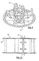
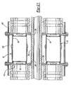
- Each of the bearing packs 60 are operatively mounted to the power cams 46 and 48 as shown in figures 5 and 20 .
- the power cams 46 and 48 have opposed facing tracks 75 and 77 upon which bearings 70 and 72 ride.
- the walls 64 or 66 are removably attached to the legs 65 and top 68 by bolts 79. In this way, the side walls with bearings 70 and 72 attached can be assembled with the bearing 70 and 72 between and engaging tracks 75 and 77.
- the bearings are preloaded by a retractor preload spring assembly 81 shown in Figure 6 .
- the power bearing 70 is mounted upon pin 73 and retractor bearing 72 is mounted upon pin 73 through preload spring 81 and retractor carrier 82. Due to the slots 87 in spring 81, the bearing 72 is biased with respect to pin 73 and bearing 70. The distance between facing tracks 75 and 77 is slightly less than the combined radii of bearings 70 and 72 ( FIG 5 ). In this way, when installed, the bearings are slightly pre-loaded. This insures contact at all times and insures tolerance take-up. Additionally, the spring 81 permits movement between bearings 70 and 72 without binding the bearings 70 and 72 with respect to tracks 75 and 77.
- roller bearings 70 are forced against and roll on tracks 77 of power cams 46 and 48 to cause them to rotate around axis A when the combustion in the power cylinder pushes the intake piston 38 and exhaust piston 40 apart ( FIGS 1 and 2 ).
- the roller bearings 72 act as idlers to maintain bearing contact with tracks 75 and 77, and the roller bearings 72 also assist in rotating the power cams around axis A when the momentum vector of each piston assembly is larger (and towards the top of the piston) than the force of acceleration being imparted to the piston assembly by the power cam. Obviously, the opposite may occur under other special circumstances. Roller bearings 70 drive the cams 46 and 48 during the power stroke of pistons 38 and 40.
- the small roller bearings or retraction bearings 72 roll on the tracks 75 of the power cams 46 and 48 respectively to actuate the intake piston 38 and exhaust piston 40 to assist in pulling the intake piston 38 and exhaust piston 40 to the end of the bottom dead center of the stroke.
- the intake piston 38 and exhaust piston 40 are then pushed together by the large bearings or roller bearings 70 rolling on the tracks 77. (i. e. when the acceleration force vector towards the piston top is larger than the momentum vector which is opposite in direction).
- the large roller bearings 70 may have sufficient energy to position the intake piston 38 and the exhaust piston 40 the full travel of the stroke.
- the small roller bearings 72 may have to assist to position the intake and exhaust pistons to bottom dead center.
- the track 77 of the power cams 46 and 48 are suitably contoured to a slightly larger radius than the large bearings 70 so that the bearing outer race will hydroplane on the cam surface, minimize the contact footprint, minimize the differential velocity of individual segments within the contact footprint as the bearing follows the radially aligned tracks, provide a built in cushioning, and prevent metal to metal contact.
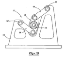
- the bearing packs are operatively supported by a four bar linkage assembly 172 ( Fig. 2 ).
- the assembly 172 has four bars connected between the mounting bars 174 on plate 170 and a bearing 178 ( FIG. 2 ), mounted to pin 176 ( FIG. 4 ).
- the bearing 178 is coaxial with pin 73 ( FIG. 4 ) and bearings 70 and 72 ( FIG. 4 ). In this way, there is no bending moment in the pistons 38 and 40.
- the four bar linkage 172 allows the linear movement of pistons 38 and 40 to be translated into rotational movement of the cams 46 and 48 with none of the reactive forces caused by the pistons driving the cams being translated through the pistons 38 and 40 to the cylinder wall 98.
- the four bar linkage assembly 172 is further illustrated in figures 19 and 20 .
- the four bar linkage assembly 172 guides the pistons 38 and 40 and reacts the side load of the cams 46 and 48 to the link mount points I at 180 and II at 182. Since the center coupler link or bearing 178 has a revolute center, none of the cams 46 and 48 side load is transmitted to the piston 38 and 40 and piston ring 130. There is a precise relationship between the geometry of the links 184 to give the desired straight line motion of the piston ring 130 and pistons 38 and 40. The relationship is the combination of the lengths of the four bar linkage assembly 172 components and the location of the mounting points 180 and 182.
- the pistons 38 and 40 have a stroke of 5.08 cm (2.0 inches).
- an additional 2.54 mm (0.1 inches) was added to each end of the stroke.
- the lengths of the components were selected for a stroke of 5.59 cm (2.2 inches).
- Coupler link 178 Stroke 5.59 cm (2.20 inches)
- Link Length 184 5.05 cm (1.990 inches)
- FIGS. 8A-8F The engine's operating cycle is best illustrated by the schematic drawings of FIGS. 8A-8F where FIG. 8A illustrates top dead center.
- FIG. 8B illustrates the power stroke cycle
- FIG. 8C is exhausting the power cylinder
- 8D-8E is charging the base compression and purging the power cylinder
- 8F illustrates the compression stroke cycle.
- the intake 38 and exhaust 40 pistons are located at the top dead center of their strokes and intake piston 38 and exhaust piston 40 are at the end of the compression stroke and in the power stroke and positioned as close to each other for correct compression ratio.
- the air in the working portion or compression chamber 29 of the power cylinder (the volume between intake and exhaust pistons) is fully compressed and fuel is timely introduced through the fuel nozzle injector 30 to cause an explosion forcing the pistons to separate.
- the inlet check valve 85 is open since the air on the upstream and downstream sides of the check valve 85 is basically at the same pressure or the pressure upstream is still slightly greater than the intermediate inlets 86 and 88 and the transfer tube intake or jumper 84.
- an o-ring seal 83 is used. This seal also accommodates the thermal differentials between the cylinder 36 and the plate 170. Also the pressures on the back sides of intake piston 38 and exhaust piston 40 are similar since they are in fluid communication with inlet port 80 via the intake jumpers 84 and the inlet passages 86 and 88. The exhaust port 90 is closed off by exhaust piston 40.
- the power cylinder 36 is supported radially by a low spring rate o-ring seal 83 and is constrained in the engine by features on the endplate. These features maintain concentricity with the connecting rods 56 and 58 and rod seal hole 190 in the endplate 170.
- the axial location of the cylinder can be adjusted by a shim 251 to account for the tolerance of the machined components.
- the intake and exhaust endplates 170 are identical so the shim 251 is also used to fill the area on the intake side in the location where the spring 250 resides on the exhaust endplate 170.
- the power cylinder 36 is loaded against the intake endplate 170 by the spring 250 that reacts on the other end to the exhaust endplate 170.
- the spring 250 (currently a wave spring) has sufficient spring force to overcome an inadvertant rub of the piston ring 130 or piston skirt on the power cylinder inner wall 98.
- the pistons are still moving apart and travelling toward bottom dead center and the exhaust ports 90 are opening and inlet passages 86 are blocked from communicating with the compression chamber 29 and are closed off by the check valve 85 so that air cannot flow towards the inlet 80. Consequently, pressure of the intake air continues to build under the piston. The exhaust gases are leaving the compression chamber. At this point of the cycle the pressure of fluid in the assembly compression chamber 29 of the power cylinder assembly 36 is quickly reducing towards its lowest value.
- the exhaust ports 90 are fully opened and the inlet passages 86 and 88 are in full communication with the compression chamber.
- This scavenges or purges the compression chamber 29 of power cylinder assembly 36 by allowing air trapped in the intake jumper 84 under a pressure higher than the compression chamber 29 to fill the power cylinder.
- the air captured in jumper 84 is preheated by being in indirect heat exchange with the combustion products during the combustion process with a consequential increase in engine efficiency, because this allows the piston top to run at higher temperatures which allows high power density levels, and the thermal tapering of the cylinder is decreased. However, this percentage must be managed, too much is a detriment to overall engine efficiency.
- FIGS. 8B and 8C the air trapped behind the intake piston 38 and exhaust piston 40 is blocked from the compression chamber 29 by the intake piston 38 and that the intake jumpers 84 are only in communication with the volumes behind the intake and exhaust pistons 38 and 40. This air is completely trapped while the pistons are still in their power stroke. Hence, the power stoke further compresses this air. Since the pistons are close to the end of their stroke during the remaining portion of the power stroke as is viewed in the schematics depicted in FIGS. 8B and 8C and 8D the movement of the intake and exhaust pistons creates a very high pressure of remaining base compression air.
- FIGS. 8E and 8F depict the compression cycle where the pistons are actuated by the power cams 46 and 48 toward top dead center which is the transition point of the power stroke ( FIG. 8A ).
- the intake piston 38 and exhaust piston 40 move toward each other and pass over the inlets 86 and 88 and exhaust ports 90, the air trapped in the compression chamber 29 of the power cylinder compresses which causes the pressure to increase until it reaches the maximum value at the end of the stroke (top dead center) FIG. 8A .
- the engine's characteristics can be changed. For example, by adjusting the length of the flats in the power cams 46 and 48, the acceleration, velocity, emissions, power, etc., can be altered.
- engine 10 does not require valving, such as the poppet type valves used for opening and closing the intake and exhaust ports inasmuch as these ports in this engine are opened and closed by virtue of the intake and exhaust pistons.
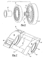
- the base compression cylinder assembly is generally shown at 95 as partially surrounding cylinder 36 and includes a base compression cylinder manifold 92 which is mounted through tie bolts 93 and nuts 91 to an air intake manifold 89.
- the tie bolts 93 extend through the intake jumpers 84.
- the power cylinder assembly 36 is mounted within the manifold openings 94.
- the power cylinder assembly 36 is shown in figure 7a and will be discussed in greater detail below.
- the intake check valves 85 FIGS. 8A, 8B , 8C, 8D ; 8E ) are reed valves which mount in inlets 80 of the air intake manifold 89.
- the tie bolts 93 and nuts 91 connect the power cylinder assembly 36 and the base compression assembly 95 together into a single package. Each of these packages are then mounted between the plates 170 ( FIG. 9 ). The plates 170 are then bolted to the outer case 12.
- the openings 94 of the manifolds 89 and 92 have slots 106 and 108 for receipt of O-rings 110.
- spring 112 is preferably a straight spring and spring 114 is preferably a V-shaped spring.
- the V-shaped spring 114 is shown in more detail in Figure 7d .
- Spring 114 is preferably made from an annular inner sleeve 115 brazed to an annular outer sleeve 117 at one end 119 thereof.
- Both springs 112 and 114 are preferably made of low thermal conductivity material.
- the springs 112 and 114 are pinned by pins 116 to the cylinder assembly 36 and more particularly to second tube 102.
- the pins 116 are preferably press fit into openings in the power cylinder assembly 36 and more particularly second tube 102.
- an opening is also provided in the manifold for receipt of pin 116.
- the use of springs 112 and 114 in conjunction with O-rings 110 provides a proper seal, but also allows for balancing of the spring rates between the coupled elements.
- a further O-ring 110 is mounted between plate 170 and power cylinder assembly 36 to complete the seal. A shim is shown in this figure.
- power cylinder assembly 36 in accordance with the invention will be discussed.
- the power cylinder assembly 36 is constructed of three different materials to both block and facilitate heat transfer and in particular to maintain the cylinder at a fairly consistent and average temperature along its entire length. It is critical that the power cylinder temperature be maintained as close to uniform as possible to prevent distortion of the power cylinder assembly 36.
- the diameter of the cylinder 36 could vary, creating difficulties with wear, piston gas bypass, loss of efficiency; and in the present engine, difficulties with the air bearings which will be described in greater detail below.
- Typical internal combustion engine cylinders expand in hotter regions creating a coning or tapering effect. By maintaining the cylinder temperature within a narrower range along its length, there is no appreciable coning or tapering effect.
- the temperature of the cylinder 36 is going to be higher than that found in typical internal combustion engines. This does not create a problem for this engine for several reasons.
- the cylinder 36 doesn't contain oil as a lubricant, air is used, the thermal mass and thermal conductivity are lower, and the frictional heating created by piston side loads and oil shearing is not an issue with this engine. Therefore, higher temperatures are acceptable.
- the key is to apportion the heat generated by combustion along the length of the cylinder 36 in a generally uniform manner. Heat apportionment is achieved by using three separate materials in cylinder 36.
- the first material is steel, preferably A286.
- a steel tube 100 is used. As illustrated in Fig 7A , inlets 86 are formed in tube 100. This material has a high alpha (thermal expansion coefficient) and low conductivity.
- Mounted about tube 100 is a second tube 102 of material made from copper.
- tube 102 does not have to be a tube but could be strips of material etc.
- Tube 102 is in two parts and is mounted adjacent the combustion chamber forming a gap between the two parts at the combustion chamber. Copper has a high alpha and high conductivity.
- the third material is a stainless steel sleeve 104 mounted about the combustion chamber and partially covering tube 102. This sleeve 104 has a low alpha and very low conductivity.
- the comparative alphas are critical so that the sleeve to sleeve mechanical contact is maintained at various temperatures and thermal gradients.
- the mechanical contact is primarily the result of thermal assembly with a minor role played by brazing. Obvious, to one skilled in the art this same result could be obtained using other mechanically constrained interfaces or braze/solders.
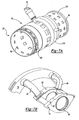
- the piston assemblies 120 include a piston top 122, a ring pack top 124, ring pack bottom 126, a piston base 128, and a piston ring 130.
- the various components which make up the piston assemblies 120 are bolted together by bolts (not shown) that are inserted into protrusions 132 extending from piston top 122 through protrusions 134 extending from piston base 128.
- the protrusions 132 extend through openings 136 on ring pack top 124 and bottom 126.
- the protrusions 132 and 134 and the bolts once again allow the spring rates to be managed.
- the piston tops 122 are specially constructed to reduce the radiant heat effect against the cylinder walls 98.
- the face 42 of the exhaust piston 40 and the face 44 of the intake piston 36 have overlapping surfaces 142 and 144 about the outer perimeter of the faces. These overlapping surfaces 142 and 144 shield the cylinder wall from radiant heat generated during combustion and traps the radiant heat in the combustion chamber. It should be appreciated that the overlapping surfaces could have a different shape.
- the protruding portion 142 could be on intake piston 38 and portion 144 could be on piston 40.
- a fuel injection cavity 164 is provided in the piston top.
- the cavity 164 is longer than it is wide to direct fuel along the path for complete combustion and to insure that no liquid fuel contacts a solid surface prior to combustion.
- the piston ring 130 is preferably a split piston ring with hydrostatic lift pockets 244. Pressurized air flows to the circumferentially spaced pockets 244 formed in each of the split rings via small diameter flex tubes 148.
- the flex tubes 148 are generally U-shaped to allow for a defined spring rate curve. Flex tubes 148 are plugged into a central air manifold 150 which receives pressurized air which is piped from the piston base 128. The pressurized air flows from the connecting rods 56 and 58 and into the openings in manifold 150. See figure 13 .
- a retaining wall 154 receives the free ends of flex tubes 148 which are in turn fed through the seal 158, and then plugged into ring 130. See figures 11 , 12 and 13 .
- the retaining wall 154 has a plurality of slots 156 for receipt of tubes 148 and seals 158.
- the slots 156 allow for lateral movement of tubes 148.
- the seals 158 have a face plate 160 and relatively long body 162.
- the body 162 receives the tube 148 and fits in slot 156 and face plate 160 engages wall 154.
- the long body 162 acts as an effective seal within slot 156 and against the tube 148.
- the face plate seals the opening in slot 156. This combination of sealing methods seals combustion gasses out of the cavity in pistons 38 and 40.
- the air supplied by the tubes 148 flows into the lift pockets 244 in the ring 130 to lift the pistons 38 and 40 off the cylinder wall.
- the pockets 244 are equally spaced or arranged for optimum positioning around the circumference of the piston rings so that the air admitted compresses the piston ring relative to the cylinder and additionally locates the piston.
- Each of the tubes 148 are bent in a generally U-shaped configuration and since one end is affixed to the piston and the other end is affixed to the piston ring, the pressure in the tubes and the stress in the tube walls will create a force that together with the hydrostatic lifting forces will space and float the piston and piston rings relative to the walls of the power cylinders.
- Tubes 148 are made from a suitable flexible and resilient material (either metal or a composite material) that exhibit good compliant characteristics so as to have a sufficient spring rate to properly load the piston rings as was described immediately above.
- air for the hydrostatic bearings lubricates and cools the piston rings and provides additional combustion air albeit a small amount.
- the hydrostatic bearings float the piston and piston rings which serve to minimize the side loadings and friction. The side loadings are further eliminated by use of the four bar linkage system. The centering action of the hydrostatic bearings also serves to minimize blowby between the ring and the cylinder.
- the air bearing piston ring 130 is a low mass airflow device but, more importantly, only requires 689 kPa - 1379 kPa (100 to 200 psig) to operate. These lower actuation pressures result in several benefits.
- One is a very low parasitic power loss (e. g. the power required to supply this air would run from 0.6 to 3.2hp, respectively for a 50 hp cylinder).
- pressurizing ambient air to 689 kPa or 1379 kPa (100 or 200psig) results in less heat added to the air. Therefore its temperature is not increased substantially. Consequently, the value of the pressurized air as a coolant for the piston ring 130 is enhanced.
- Lower actuation pressure is achieved by depressed trenches 242 that surround the support pockets 244. These trenches 242 communicate with the low pressure side of the pistons 38 and 40 (e. g. opposite the combustion side). Trenches 242 consist of circumferential grooves 246 and by-pass slots 248. Slots 248 are typically at a lower pressure, therefore the air bearing effect works. To maximize the amount of lift for the provided actuation pressure, the flowable area of the pockets 244 is maximized for the circumference.
- this ABPR operating in a 50hp cylinder could provide a ring to cylinder clearance of 0.229 mm (.00090") with 0psig above the ring 130 and a low 0.00254 mm (.00010”) or even .00000mm (.00000”) at combustion at top dead center with supply pressures of 689 kPa to 1379 kPa (100psig to 200psig), if the designer should desire.
- any high pressure combustion leakage (blowby) is quickly short circuited by the trenches 242 and prevents backfeeding into the inclusions.
- This short circuiting maintains the cooling effect of the supply air at the ABPR, prevents combustion product contamination of the pads/inclusions, and insures high frequency response of the ABPR levitation system to changes in its force equilibrium.
- This wear would be minimal for several reasons: no piston side loads, seat-out 0 mm (0"clearance) occurs at very low piston velocities and wear is a function of frictional force and velocity differentials.
- the air bearing piston ring 130 is lubricated with air rather oil.
- the purpose of the piston ring 130 is to minimize the leakage of the combustion pressure and this requires a very small radial clearance between the ring 130 and cylinder wall 98.
- the clearance between the piston ring 130 and the wall 98 is small and is just large enough to levitate the load, i. e. , the piston 38 and 40.
- the unique feature of the piston ring 130 is that is self equalizing. For example, if too much air is leaking out around the edges of the lift pocket or support pockets 244, the clearance decreases to reduce the airflow rate to equal the air supply rate. Conversely, if the air leakage out of the edges of the lift pockets 244 is too small, the air pressure increases and lifts the load to attain the correct airflow.
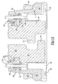
- the piston rod seal pack 188 seals the piston rods or connecting rods 56 and 58 with respect to the openings 190 in plate 170.
- the connecting rods 56 and 58 reciprocate within seal packs 188 mounted in openings 190.
- the seal packs 188 are constructed to seal the rods 56 and 58 with respect to openings 190 and to allow for slight lateral movement of the rods 56 and 58 and the seal pack 188 relative to the plate 170.
- the seal packs 188 have an outer casing 192 and two inner casings 194 and 196. The casings are held together with a snap ring 198. It should be appreciated that a single housing could be used, but for ease of manufacture, three separate casings were used. To use the high grade seals in a one piece installation would have contorted the seals beyond their elastic limits and decreased their sealing effectiveness and durability.
- the casings contain seals 199 which seal against the connecting rod.
- An 0-ring 202 is mounted between casings 194 and 196 and shares a groove in casings 192 and 196.
- a second O-ring 200 is mounted between plate 170 and casing 192.
- the second 0-ring 200 shares a groove formed partly in each of these parts. Having shared grooves for supporting the 0-rings allows for better sealing and for some movement with respect to the sealed components, and provides for high strength retention to oppose the oscillating movements of the rods 56 and 58 since the O-ring is practically in pure shear.
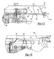
- the air supply line 204 for feeding pressurized air to the ring 130 will be described.
- the air supply line 204 connects to the bearing pack 60.
- the pack 60 has internal channels which direct air to the connecting rods 56 and 58 which have a channel 206 for routing air to manifold 150.
- the line 204 has a connector 208 for connecting the bearing pack line 210 to the outer casing line 212.
- Outer casing line 212 is connected to casing 12 and to a supply of pressurized air.
- a standard connector 211 is used to connect line 212 to casing 12.
- the connector 208 has a long body with an O-ring cavity 216. The long body facilitates sealing because a long tube in a long hole minimizes leakage. The use of an O-ring further reduces leakage. As a result, the connector 208 seals against leakage while simultaneously allowing tube 210 to move or reciprocate with respect to tube 212 as a result of movement in the bearing pack 60.
- connection between the cams 46 and 48 and the output or rotary shaft 14 is illustrated at 220.
- the connection at 220 is through gear teeth 222 on both the cam and shaft.
- the oil slinger 230 is illustrated in figure 18 .
- the oil slinger 230 is preferably part of the cams 46 and 48.
- Slinger 230 extends along the rotary shaft 14.
- slinger 230 is a hollow tube with a plurality of openings which allow it to be slung out to lubricate the bearing packs 60. The holes face the bearing packs 60. Oil is fed to the slingers 230 through feed line 232. Tube 232 is connected to an oil reservoir and pump to direct oil to slinger 230.
- Shaft seal tube 234 is concentric with and receives the rotary shaft 14.
- the shaft seal tube 234 is connected between the end plates 170.
- the seal tube 234 is a cylinder with a flange 236 on both ends.
- the tube 234 is sealed with an 0-ring 236 to each of the end plates 170.
- Tube 234 eliminates the need for a seal from the stationary endplate to the rotating rotary shaft 14.
- the seal tube 234 also provides support to the endplate 170 and adds stiffness.
- the end plates 170 are supported on the outside diameter by the center case 238 and the bearing case 240.
- the center case 238 and the bearing case 240 define the outer case assembly 12.
- the endplate 170 is supported on the inside diameter by the shaft seal tube 234. The loads from the pistons 38 and 40 are transmitted to the end plates 170. With the end plates 170 supported at the inside and outside diameters, the link mount points 180 and 182 deflections are minimized. The minimized deflection of the link mount points 180 and 182 is important to maintain the straight line motion of the bearing packs 60 attached to the pistons 38 and 40.
Landscapes
- Engineering & Computer Science (AREA)
- Mechanical Engineering (AREA)
- General Engineering & Computer Science (AREA)
- Chemical & Material Sciences (AREA)
- Combustion & Propulsion (AREA)
- Cylinder Crankcases Of Internal Combustion Engines (AREA)
- Combustion Methods Of Internal-Combustion Engines (AREA)
Claims (11)
- Verbrennungszylinder (36) für einen Verbrennungsmotor, welcher Folgendes aufweist:ein erstes Element (100), das durch ein erstes Hohlrohr mit einer vorbestimmten Länge definiert ist, wobei das erste Hohlrohr dazu eingerichtet ist, mindestens einen Kolben für eine hin- und hergehende Bewegung innerhalb des ersten Hohlrohres aufzunehmen, wobei das erste Hohlrohr einen Brennraum definiert und wobei ein Kraftstoff-Luft-Gemisch eingeführt, verdichtet und gezündet werden kann, wobei das erste Hohlrohr einen hohen Wärmeausdehnungskoeffizienten und eine niedrige Leitfähigkeit aufweist;ein zweites Element (102), das dem ersten Element benachbart ist, wobei das zweite Element einen hohen Wärmeausdehnungskoeffizienten und eine hohe Leitfähigkeit aufweist;ein drittes Element (104), das um das erste Hohlrohr herum dem Brennraum des ersten Hohlrohres benachbart positioniert ist, wobei das dritte Element einen niedrigen Wärmeausdehnungskoeffizienten und eine niedrige Leitfähigkeit aufweist;wobei das erste, zweite und dritte Element (100, 102, 104) interagieren, um die Verjüngung des ersten Elements (100) entlang der vorbestimmten Länge zu verringern, indem zunächst durch das dritte Element Wärme innerhalb des Brennraums zurückgehalten wird und die Ausdehnung des Brennraums verringert wird und danach in dem Brennraum entwickelte Wärme entlang des ersten Elements verteilt wird, indem die Wärme durch das zweite Element geleitet wird, um eine im Allgemeinen gleichförmige Temperatur entlang der Länge des ersten Elements (100) aufrechtzuerhalten.
- Verbrennungszylinder nach Anspruch 1, wobei sich das zweite Element (102) bis zu einer Position ausdehnt, die dem Brennraum benachbart ist.
- Verbrennungszylinder nach Anspruch 1, wobei das zweite Element (102) durch ein zweites Hohlrohr definiert ist, das koaxial um das erste hohle Element herum positioniert ist.
- Verbrennungszylinder nach Anspruch 1, wobei das zweite Element (102) aus Kupfer hergestellt ist.
- Verbrennungszylinder nach Anspruch 1, wobei das dritte Element (104) aus Edelstahl hergestellt ist.
- Verbrennungszylinder nach Anspruch 1, wobei das erste Element (100) eine vorbestimmte Länge aufweist, welche dazu eingerichtet ist, zwei gegenüberliegende Kolben aufzunehmen, wobei das erste Element zwei Enden und einen Mittelabschnitt aufweist, wobei der Brennraum im Allgemeinen an dem Mittelabschnitt des ersten Elements angeordnet ist, wobei das zweite Element an dem Brennraum offen ist und sich entlang des ersten Elements bis zu den Enden des ersten Elements erstreckt.
- Verbrennungszylinder nach Anspruch 6, wobei das zweite Element (102) mindestens zwei separate Teile aufweist, wobei jeder Teil sich von einem dem Brennraum benachbarten Bereich bis zu einem jeweiligen Ende des ersten Elements erstreckt.
- Verbrennungszylinder nach Anspruch 6, wobei das dritte Element (104) das erste Element an dem Brennraum umgibt.
- Verbrennungszylinder nach Anspruch 1, wobei das dritte Element (104) eine Hülse ist.
- Verbrennungszylinder nach Anspruch 1, wobei das dritte Element (104) das zweite Element (102) teilweise bedeckt.
- Verbrennungsmotor, welcher Folgendes aufweist:mindestens zwei Verbrennungszylinder (36) nach Anspruch 1 oder 6, die jeweils gegenüberliegende Enden mit zwei gegenüberliegenden Kolben in jedem der zwei Verbrennungszylinder aufweisen, wobei jeder der Kolben eine Kolbenstange (56, 58) aufweist, die sich von dem Kolben aus erstreckt und mit einem Lagersatz (60) verbunden ist, gegenüberliegende Nockenbahnen (46, 48), die mit den Lagersätzen in Wirkverbindung stehen, ein Gelenkviereck (72), das mit einem Paar Befestigungsplatten verbunden ist, wobei der Lagersatz mit dem Gelenkviereck verbunden ist, Befestigungsplatten, die den gegenüberliegenden Enden der mindestens zwei Verbrennungszylinder benachbart angebracht sind, wobei die Befestigungsplatten Öffnungen zur Aufnahme der Kolbenstangen (56, 58) aufweisen, derart, dass die Kolbenstangen eine hin- und hergehende Bewegung innerhalb der Öffnungen ausführen, wobei die Öffnungen eine Dichtung aufweisen, wobei die Kolben einander zugewandte Verbrennungsflächen mit Außenumfängen aufweisen, wobei die Außenumfänge der Verbrennungsflächen jeweils eine profilierte Fläche aufweisen, wobei die profilierten Flächen aneinanderpassend sind, um einen Brennraum zwischen den Verbrennungsflächen der Kolben zu bilden, welcher im Allgemeinen geschlossen ist, um den Wärmeverlust aus dem Brennraum während der Verbrennung zu verringern.
Applications Claiming Priority (4)
| Application Number | Priority Date | Filing Date | Title |
|---|---|---|---|
| US34178101P | 2001-12-18 | 2001-12-18 | |
| US341781P | 2001-12-18 | ||
| PCT/US2002/031438 WO2003106827A1 (en) | 2001-12-18 | 2002-10-02 | Internal combustion engine using opposed pistons |
| PCT/US2003/018902 WO2005008038A2 (en) | 2001-12-18 | 2003-06-17 | Internal combustion engine using opposed pistons |
Publications (3)
| Publication Number | Publication Date |
|---|---|
| EP1474594A1 EP1474594A1 (de) | 2004-11-10 |
| EP1474594A4 EP1474594A4 (de) | 2008-12-10 |
| EP1474594B1 true EP1474594B1 (de) | 2012-08-15 |
Family
ID=34315859
Family Applications (1)
| Application Number | Title | Priority Date | Filing Date |
|---|---|---|---|
| EP02768951A Expired - Lifetime EP1474594B1 (de) | 2001-12-18 | 2002-10-02 | Gegenkolben verwendender verbrennungsmotor |
Country Status (3)
| Country | Link |
|---|---|
| EP (1) | EP1474594B1 (de) |
| AU (1) | AU2002332015A1 (de) |
| WO (1) | WO2003106827A1 (de) |
Cited By (2)
| Publication number | Priority date | Publication date | Assignee | Title |
|---|---|---|---|---|
| CN104675517A (zh) * | 2015-02-13 | 2015-06-03 | 李晓可 | 系列化模块化水平正对置h型四联发动机 |
| US9771861B2 (en) | 2014-09-09 | 2017-09-26 | Avl Powertrain Engineering, Inc. | Opposed piston two-stroke engine with thermal barrier |
Families Citing this family (8)
| Publication number | Priority date | Publication date | Assignee | Title |
|---|---|---|---|---|
| CN100429431C (zh) * | 2004-11-24 | 2008-10-29 | 赵荃 | 直线运动与旋转运动转换的功率传输机构 |
| US9004038B2 (en) | 2011-12-29 | 2015-04-14 | Etagen, Inc. | Methods and systems for managing a clearance gap in a piston engine |
| US9169797B2 (en) | 2011-12-29 | 2015-10-27 | Etagen, Inc. | Methods and systems for managing a clearance gap in a piston engine |
| US9097203B2 (en) | 2011-12-29 | 2015-08-04 | Etagen, Inc. | Methods and systems for managing a clearance gap in a piston engine |
| US10215229B2 (en) | 2013-03-14 | 2019-02-26 | Etagen, Inc. | Mechanism for maintaining a clearance gap |
| CN113169654B (zh) | 2018-07-24 | 2024-11-15 | 曼斯普林能源股份有限公司 | 线性电磁机 |
| MX2021007476A (es) | 2018-12-18 | 2021-09-28 | Mainspring Energy Inc | Sistema de generador lineal integrado. |
| US12255514B2 (en) | 2021-07-30 | 2025-03-18 | Mainspring Energy, Inc. | Systems and methods for flexure-based bearing mounting |
Family Cites Families (11)
| Publication number | Priority date | Publication date | Assignee | Title |
|---|---|---|---|---|
| US1788140A (en) | 1928-04-19 | 1931-01-06 | Packard Motor Car Co | Internal-combustion engine |
| US2076334A (en) | 1934-04-16 | 1937-04-06 | Earl A Burns | Diesel engine |
| DE1945924A1 (de) | 1969-09-11 | 1971-03-18 | Lenger Karl Werner | Freikolbenmaschine |
| US4111104A (en) | 1977-03-30 | 1978-09-05 | General Motors Corporation | Engine with low friction piston |
| US4455974A (en) | 1981-01-08 | 1984-06-26 | Cummins Engine Company, Inc. | Gas bearing piston assembly |
| JPS6213758A (ja) * | 1985-02-28 | 1987-01-22 | Toyota Motor Corp | 断熱エンジン用シリンダブロツク |
| US4681326A (en) | 1985-06-10 | 1987-07-21 | Cummins Engine Company, Inc. | Gas lubricated piston ring assembly |
| JPH0776541B2 (ja) * | 1986-05-07 | 1995-08-16 | 本田技研工業株式会社 | 繊維強化シリンダブロツク |
| US5375567A (en) | 1993-08-27 | 1994-12-27 | Lowi, Jr.; Alvin | Adiabatic, two-stroke cycle engine |
| US5551383A (en) | 1995-07-20 | 1996-09-03 | Novotny; Rudolph J. | Internal combustion engine utilizing pistons |
| US6138630A (en) * | 1999-10-28 | 2000-10-31 | Metalicos De Tecnologia Avanzada, S.A. De C.V. | Cylinder liners for aluminum motor blocks and methods of production |
-
2002
- 2002-10-02 EP EP02768951A patent/EP1474594B1/de not_active Expired - Lifetime
- 2002-10-02 AU AU2002332015A patent/AU2002332015A1/en not_active Abandoned
- 2002-10-02 WO PCT/US2002/031438 patent/WO2003106827A1/en not_active Ceased
Cited By (3)
| Publication number | Priority date | Publication date | Assignee | Title |
|---|---|---|---|---|
| US9771861B2 (en) | 2014-09-09 | 2017-09-26 | Avl Powertrain Engineering, Inc. | Opposed piston two-stroke engine with thermal barrier |
| CN104675517A (zh) * | 2015-02-13 | 2015-06-03 | 李晓可 | 系列化模块化水平正对置h型四联发动机 |
| CN104675517B (zh) * | 2015-02-13 | 2017-04-12 | 李晓可 | 系列化模块化水平正对置h型四联发动机 |
Also Published As
| Publication number | Publication date |
|---|---|
| WO2003106827A1 (en) | 2003-12-24 |
| EP1474594A1 (de) | 2004-11-10 |
| AU2002332015A1 (en) | 2003-12-31 |
| EP1474594A4 (de) | 2008-12-10 |
Similar Documents
| Publication | Publication Date | Title |
|---|---|---|
| US7124716B2 (en) | Internal combustion engine using opposed pistons | |
| KR100922024B1 (ko) | 왕복동 피스톤엔진 | |
| AU2010213844B8 (en) | Piston assembly for a Stirling engine | |
| AU728568C (en) | Stirling engine | |
| JP3429764B2 (ja) | 連接棒のないピストンを備える流体作動機械 | |
| US5551383A (en) | Internal combustion engine utilizing pistons | |
| WO1997027391A1 (en) | Crosshead system for stirling engine | |
| US6282895B1 (en) | Heat engine heater head assembly | |
| EP1474594B1 (de) | Gegenkolben verwendender verbrennungsmotor | |
| US5865091A (en) | Piston assembly for stirling engine | |
| US5813229A (en) | Pressure relief system for stirling engine | |
| FI66239C (fi) | Maskin utfoerande en raetlinjig roerelse | |
| US11927128B2 (en) | Rotary machine with hub driven transmission articulating a four bar linkage | |
| US6846163B2 (en) | Rotary fluid machine having rotor segments on the outer periphery of a rotor core | |
| US6186098B1 (en) | Coaxial oscillating axisymmetric engine | |
| WO2005008038A2 (en) | Internal combustion engine using opposed pistons | |
| WO1998001657A1 (en) | Rotary engine | |
| US20230073004A1 (en) | Rotary machine with hub driven transmission articulating a four bar linkage | |
| US8464685B2 (en) | High performance continuous internal combustion engine | |
| KR100292987B1 (ko) | 동축형 왕복엔진의 밸브기구 | |
| US3914075A (en) | Sliding partition rotary engine with rectilinear seals | |
| AU760360B2 (en) | Stirling engine | |
| AU2014279374B2 (en) | Stirling engine | |
| KR100282064B1 (ko) | 동축형 왕복엔진 | |
| Shaw et al. | The Shaw Type Compressor a New Concept in Compressor Design |
Legal Events
| Date | Code | Title | Description |
|---|---|---|---|
| PUAI | Public reference made under article 153(3) epc to a published international application that has entered the european phase |
Free format text: ORIGINAL CODE: 0009012 |
|
| 17P | Request for examination filed |
Effective date: 20040719 |
|
| AK | Designated contracting states |
Kind code of ref document: A1 Designated state(s): AT BE BG CH CY CZ DE DK EE ES FI FR GB GR IE IT LI LU MC NL PT SE SK TR |
|
| AX | Request for extension of the european patent |
Extension state: AL LT LV MK RO SI |
|
| A4 | Supplementary search report drawn up and despatched |
Effective date: 20081112 |
|
| RIC1 | Information provided on ipc code assigned before grant |
Ipc: F02B 75/28 20060101AFI20040108BHEP Ipc: F01B 3/00 20060101ALI20081106BHEP |
|
| 17Q | First examination report despatched |
Effective date: 20090209 |
|
| GRAP | Despatch of communication of intention to grant a patent |
Free format text: ORIGINAL CODE: EPIDOSNIGR1 |
|
| GRAS | Grant fee paid |
Free format text: ORIGINAL CODE: EPIDOSNIGR3 |
|
| GRAA | (expected) grant |
Free format text: ORIGINAL CODE: 0009210 |
|
| AK | Designated contracting states |
Kind code of ref document: B1 Designated state(s): AT BE BG CH CY CZ DE DK EE ES FI FR GB GR IE IT LI LU MC NL PT SE SK TR |
|
| REG | Reference to a national code |
Ref country code: GB Ref legal event code: FG4D Ref country code: CH Ref legal event code: EP Ref country code: AT Ref legal event code: REF Ref document number: 570972 Country of ref document: AT Kind code of ref document: T Effective date: 20120815 |
|
| REG | Reference to a national code |
Ref country code: IE Ref legal event code: FG4D |
|
| REG | Reference to a national code |
Ref country code: DE Ref legal event code: R096 Ref document number: 60243531 Country of ref document: DE Effective date: 20121011 |
|
| REG | Reference to a national code |
Ref country code: NL Ref legal event code: VDEP Effective date: 20120815 |
|
| REG | Reference to a national code |
Ref country code: AT Ref legal event code: MK05 Ref document number: 570972 Country of ref document: AT Kind code of ref document: T Effective date: 20120815 |
|
| PG25 | Lapsed in a contracting state [announced via postgrant information from national office to epo] |
Ref country code: AT Free format text: LAPSE BECAUSE OF FAILURE TO SUBMIT A TRANSLATION OF THE DESCRIPTION OR TO PAY THE FEE WITHIN THE PRESCRIBED TIME-LIMIT Effective date: 20120815 Ref country code: FI Free format text: LAPSE BECAUSE OF FAILURE TO SUBMIT A TRANSLATION OF THE DESCRIPTION OR TO PAY THE FEE WITHIN THE PRESCRIBED TIME-LIMIT Effective date: 20120815 Ref country code: CY Free format text: LAPSE BECAUSE OF FAILURE TO SUBMIT A TRANSLATION OF THE DESCRIPTION OR TO PAY THE FEE WITHIN THE PRESCRIBED TIME-LIMIT Effective date: 20120815 |
|
| PG25 | Lapsed in a contracting state [announced via postgrant information from national office to epo] |
Ref country code: SE Free format text: LAPSE BECAUSE OF FAILURE TO SUBMIT A TRANSLATION OF THE DESCRIPTION OR TO PAY THE FEE WITHIN THE PRESCRIBED TIME-LIMIT Effective date: 20120815 Ref country code: BE Free format text: LAPSE BECAUSE OF FAILURE TO SUBMIT A TRANSLATION OF THE DESCRIPTION OR TO PAY THE FEE WITHIN THE PRESCRIBED TIME-LIMIT Effective date: 20120815 Ref country code: PT Free format text: LAPSE BECAUSE OF FAILURE TO SUBMIT A TRANSLATION OF THE DESCRIPTION OR TO PAY THE FEE WITHIN THE PRESCRIBED TIME-LIMIT Effective date: 20121217 Ref country code: GR Free format text: LAPSE BECAUSE OF FAILURE TO SUBMIT A TRANSLATION OF THE DESCRIPTION OR TO PAY THE FEE WITHIN THE PRESCRIBED TIME-LIMIT Effective date: 20121116 |
|
| PG25 | Lapsed in a contracting state [announced via postgrant information from national office to epo] |
Ref country code: NL Free format text: LAPSE BECAUSE OF FAILURE TO SUBMIT A TRANSLATION OF THE DESCRIPTION OR TO PAY THE FEE WITHIN THE PRESCRIBED TIME-LIMIT Effective date: 20120815 |
|
| PG25 | Lapsed in a contracting state [announced via postgrant information from national office to epo] |
Ref country code: DK Free format text: LAPSE BECAUSE OF FAILURE TO SUBMIT A TRANSLATION OF THE DESCRIPTION OR TO PAY THE FEE WITHIN THE PRESCRIBED TIME-LIMIT Effective date: 20120815 Ref country code: ES Free format text: LAPSE BECAUSE OF FAILURE TO SUBMIT A TRANSLATION OF THE DESCRIPTION OR TO PAY THE FEE WITHIN THE PRESCRIBED TIME-LIMIT Effective date: 20121126 Ref country code: EE Free format text: LAPSE BECAUSE OF FAILURE TO SUBMIT A TRANSLATION OF THE DESCRIPTION OR TO PAY THE FEE WITHIN THE PRESCRIBED TIME-LIMIT Effective date: 20120815 Ref country code: CZ Free format text: LAPSE BECAUSE OF FAILURE TO SUBMIT A TRANSLATION OF THE DESCRIPTION OR TO PAY THE FEE WITHIN THE PRESCRIBED TIME-LIMIT Effective date: 20120815 |
|
| PG25 | Lapsed in a contracting state [announced via postgrant information from national office to epo] |
Ref country code: SK Free format text: LAPSE BECAUSE OF FAILURE TO SUBMIT A TRANSLATION OF THE DESCRIPTION OR TO PAY THE FEE WITHIN THE PRESCRIBED TIME-LIMIT Effective date: 20120815 Ref country code: MC Free format text: LAPSE BECAUSE OF NON-PAYMENT OF DUE FEES Effective date: 20121031 Ref country code: IT Free format text: LAPSE BECAUSE OF FAILURE TO SUBMIT A TRANSLATION OF THE DESCRIPTION OR TO PAY THE FEE WITHIN THE PRESCRIBED TIME-LIMIT Effective date: 20120815 |
|
| REG | Reference to a national code |
Ref country code: CH Ref legal event code: PL |
|
| PLBE | No opposition filed within time limit |
Free format text: ORIGINAL CODE: 0009261 |
|
| STAA | Information on the status of an ep patent application or granted ep patent |
Free format text: STATUS: NO OPPOSITION FILED WITHIN TIME LIMIT |
|
| REG | Reference to a national code |
Ref country code: IE Ref legal event code: MM4A |
|
| 26N | No opposition filed |
Effective date: 20130516 |
|
| GBPC | Gb: european patent ceased through non-payment of renewal fee |
Effective date: 20121115 |
|
| REG | Reference to a national code |
Ref country code: FR Ref legal event code: ST Effective date: 20130628 |
|
| PG25 | Lapsed in a contracting state [announced via postgrant information from national office to epo] |
Ref country code: CH Free format text: LAPSE BECAUSE OF NON-PAYMENT OF DUE FEES Effective date: 20121031 Ref country code: IE Free format text: LAPSE BECAUSE OF NON-PAYMENT OF DUE FEES Effective date: 20121002 Ref country code: BG Free format text: LAPSE BECAUSE OF FAILURE TO SUBMIT A TRANSLATION OF THE DESCRIPTION OR TO PAY THE FEE WITHIN THE PRESCRIBED TIME-LIMIT Effective date: 20121115 Ref country code: LI Free format text: LAPSE BECAUSE OF NON-PAYMENT OF DUE FEES Effective date: 20121031 |
|
| PGFP | Annual fee paid to national office [announced via postgrant information from national office to epo] |
Ref country code: DE Payment date: 20130426 Year of fee payment: 11 |
|
| PG25 | Lapsed in a contracting state [announced via postgrant information from national office to epo] |
Ref country code: FR Free format text: LAPSE BECAUSE OF NON-PAYMENT OF DUE FEES Effective date: 20121031 |
|
| REG | Reference to a national code |
Ref country code: DE Ref legal event code: R097 Ref document number: 60243531 Country of ref document: DE Effective date: 20130516 |
|
| PG25 | Lapsed in a contracting state [announced via postgrant information from national office to epo] |
Ref country code: GB Free format text: LAPSE BECAUSE OF NON-PAYMENT OF DUE FEES Effective date: 20121115 |
|
| PG25 | Lapsed in a contracting state [announced via postgrant information from national office to epo] |
Ref country code: TR Free format text: LAPSE BECAUSE OF FAILURE TO SUBMIT A TRANSLATION OF THE DESCRIPTION OR TO PAY THE FEE WITHIN THE PRESCRIBED TIME-LIMIT Effective date: 20120815 |
|
| PG25 | Lapsed in a contracting state [announced via postgrant information from national office to epo] |
Ref country code: LU Free format text: LAPSE BECAUSE OF NON-PAYMENT OF DUE FEES Effective date: 20121002 |
|
| REG | Reference to a national code |
Ref country code: DE Ref legal event code: R119 Ref document number: 60243531 Country of ref document: DE Effective date: 20140501 |
|
| PG25 | Lapsed in a contracting state [announced via postgrant information from national office to epo] |
Ref country code: DE Free format text: LAPSE BECAUSE OF NON-PAYMENT OF DUE FEES Effective date: 20140501 |