EP1474324B1 - Seat for cyclist - Google Patents
Seat for cyclist Download PDFInfo
- Publication number
- EP1474324B1 EP1474324B1 EP02704981A EP02704981A EP1474324B1 EP 1474324 B1 EP1474324 B1 EP 1474324B1 EP 02704981 A EP02704981 A EP 02704981A EP 02704981 A EP02704981 A EP 02704981A EP 1474324 B1 EP1474324 B1 EP 1474324B1
- Authority
- EP
- European Patent Office
- Prior art keywords
- seat
- support members
- support
- elements
- rail
- Prior art date
- Legal status (The legal status is an assumption and is not a legal conclusion. Google has not performed a legal analysis and makes no representation as to the accuracy of the status listed.)
- Expired - Lifetime
Links
Images
Classifications
-
- B—PERFORMING OPERATIONS; TRANSPORTING
- B62—LAND VEHICLES FOR TRAVELLING OTHERWISE THAN ON RAILS
- B62J—CYCLE SADDLES OR SEATS; AUXILIARY DEVICES OR ACCESSORIES SPECIALLY ADAPTED TO CYCLES AND NOT OTHERWISE PROVIDED FOR, e.g. ARTICLE CARRIERS OR CYCLE PROTECTORS
- B62J1/00—Saddles or other seats for cycles; Arrangement thereof; Component parts
- B62J1/005—Saddles having a seating area with multiple separate weight bearing surfaces
-
- B—PERFORMING OPERATIONS; TRANSPORTING
- B62—LAND VEHICLES FOR TRAVELLING OTHERWISE THAN ON RAILS
- B62J—CYCLE SADDLES OR SEATS; AUXILIARY DEVICES OR ACCESSORIES SPECIALLY ADAPTED TO CYCLES AND NOT OTHERWISE PROVIDED FOR, e.g. ARTICLE CARRIERS OR CYCLE PROTECTORS
- B62J1/00—Saddles or other seats for cycles; Arrangement thereof; Component parts
- B62J1/007—Saddles with specific anatomical adaptations
Definitions
- the present invention relates to a seat for a cyclist, for example a bicycle seat.
- An object of the present invention is to provide a seat which allows a rider's legs and the buttocks to move freely whilst providing a relatively large area of support over the thighs and buttocks.
- EP A 0816214 proposes a saddle having saddle displacement members which, when no external force acts on them, are imparted a restoring force which keeps them in a horizontal position.
- US 6152524 proposes a hornless saddle capable of limited lateral pivotal movement about a fore and aft axis.
- WO 00/51877 proposes a saddle which rocks from side to side as a rider pedals.
- a first aspect of the present invention provides a seat for a cyclist according to claim 1.
- the seat may be suitable for fitting to a bicycle, a tricycle, a stationary cycling exercise apparatus, a pedal-powered boat, or any other apparatus or device powered or operated by cycling motion of a user's legs.
- the seat spreads the weight of the cyclist over a larger area, helping to increase rider comfort but without significantly restricting leg mobility.
- the leg support members may be adapted so that at least the upper quarter (and preferably the upper third or half) of each of the cyclist's thighs is supportable.
- the leg support members may be adapted to provide, in use, substantially continuous support for the cyclist's legs.
- the support members at one side rise and fall out of phase with the opposing support members at the other side.
- Opposing left and right side support members are coupled so that, in use, downward movement of the support members at one side drives the opposing support members at the other side upward. In this way the downward movement of one leg assists the upward movement of the other leg. This promotes a smooth cycling action and further helps to provide continuous support for each leg.
- the seat further has a central body from which each of the left and right side support members laterally extends, each support member being pivotally attached to the central body.
- the seat has at least five (and more preferably at least ten) spaced support members at each of the left and right sides of the saddle.
- the seat can adapt better to the varying angles and positions which the legs undergo during cycling.
- support members which support the leg e.g. at mid-thigh can undergo greater amounts of movement than support members which support the leg e.g. close to the buttocks.
- Gaps can be provided between adjacent support members to promote air flow to the legs and thereby improve ventilation.
- the seat may further have restoring means to restore the support members of each side to a predetermined position relative to each other after use.
- the support members may be adopted so that they are remountably detachable from the seat, e.g. in case of an accident to reduce the risk of the members inflicting injury on the rider.
- the seat may be made of metals, plastics or wood or a combination of these materials.
- the seat may have a detachable rail to enable the elements to be changed.
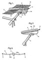
- the seat comprises a plurality of elements 5 that are supported on and are pivotable around a central body which takes the form of pivot-rail 2.
- the pivot-rail is held by bolts 14 (the front end bolt is not shown, and the rear end bolt is shown partly withdrawn for clarity) to the ends of support rails 2a that are clamped to a conventional bicycle seat post 9.
- each element 5 has two elongate support arms 20a, 20b which extend radially from opposite sides of central tubular portion 21.
- the bore 6 of tubular portion 21 of each of the elements receives pivot-rail 2 and forms a bearing surface.
- Optional low friction washers 10 are positioned between neighbouring tubular portions on the pivot-rail.
- the pivot-rail provides an axis about which the support arms can rotate substantially independently of each other, with support arms 20a, 20b extending laterally from the pivot-rail at left and right sides of the seat.
- the washers can be omitted if the axially outer faces of the tubular portions are of sufficiently low friction material or sufficiently lubricated to allow the substantially independent rotation.
- Elements 5a and 5b are non-pivotably fixed to the pivot-rail.
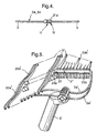
- Fig. 4 shows an under side view of one of these elements. Recessed pinch bolts 12 in tubular portion 21a clamp the element to the pivot-rail so that the respective support arms cannot rotate. These non-rotating arms provide lateral stability for the rider.
- the elements 5 provide a seating area which includes moveable support for the rider's upper thighs and posterior.
- the rider's posterior i.e. buttocks
- the rider's posterior is supported by the support arms rearwards of elements 5a and 5b, and the upper thighs (down to about mid-thigh) are supported by the support arms forward of these elements.
- the lateral extents of the arms can vary to correspond to the seating area of the rider.
- Opposing arms on the same element are coupled via the respective central tubular portion, so that as one arm is driven down it assists the upward movement of the opposing arm.
- the support arms at one side rise and fall out of phase with the opposing support arms and provide continuous support for the cyclist's legs.
- the movement of each arm is substantially independent of the movement of neighbouring arms so that the arms can adapt and conform to the instantaneous position of the rider's legs.
- each support arm 20a, 20b has a through-hole 3 through which an elastic cable 13 is threaded.
- an elastic cable 13 connects the outer ends of the left side support arms and another connects the outer ends of the right side support arms to define respectively the left and right hand edges of the seating area.
- the elastic cables form restoring means which do not substantially interfere with the rotation of elements 5, but act to restore the support members of each side to an in-line position after use.
- Fig. 5 shows a perspective view, with a cut away section, of a seat according to a second embodiment.
- the seat comprises a plurality of elements 5' that are supported on pivot-rail 2'.
- the pivot-rail is attached to the ends of support rails 2a' that are clamped to a conventional bicycle seat post 9'.
- the pivot-rail has front 23a and rear 23b portions joined by a knuckle joint 22.
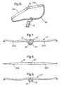
- Fig. 6 is a side view of the pivot-rail of Fig. 5 .
- the front portion carries elements intended to support the thighs of a rider
- the rear portions carries elements intended to support the posterior of the rider.
- the knuckle joint allows the angle between the two portions to be varied thereby providing a degree of customisability to further enhance rider comfort.
- the varying angle changes the overall length of the pivot-rail, but this (small) length change can be accommodated by the flexibility of the support rails and/or be taken up by the pivot-rail/support rail coupling.
- the support arms 20a', 20b' of the elements carried by the rear portion of the pivot-rail have progressively narrower spans towards the rear of the seat.
- Fig. 7 and 8 show respectively end and top views of an element 5' of the seat of Fig. 5 .
- the element 5' is formed as a one-piece plastics mouldings, such that the support arms 20a', 20b' are unitary with central tubular portion 21'.
- the plastics material has a sufficiently low friction coefficient such that spacing washers are not required between neighbouring elements.
- Through-holes 3' for receiving a respective elastic restoring cable are at the inner ends of support arms 20a', 20b'.
- the elements 5' carried by the front portion of the pivot-rail are pivotably attached to the rail such that they can rotate substantially independently of each other to provide continuous support for the rider's legs.
- the elements carried by the rear portion of the pivot rail are non-pivotably fixed to the rail to provide lateral support for the rider.
- the fixing can be by means of pinch-bolts through apertures 23 in the central tubular portions 21' of elements 5'. Other means of providing a non-pivotable fixing are known to the skilled person.
- Fig. 9 shows an end view of an alternative element 5" for the seat of Fig. 5 .
- the element or at least central tabula portion 21" is made of a sufficiently resilient material such that the element can be snap-fitted onto pivot-rail by means of the opening 24 in bore 6". In case of an accident, this allows the element to detach from the pivot-rail, reducing the danger of injury to the rider.
- the seat may incorporate both elements 5' and elements 5", the former e.g. providing non-pivotable lateral support where needed, and the latter being used at other positions.
- the rear portion of the pivot-rail and associated elements 5' and/or elements 5" can be substituted by a stationary platform (that is, stationary relative to the up and down motion of the rider's legs) e.g. approximating in shape to the rear half of a conventional saddle.
- the articulation provides a moveable support platform that acts in accordance with the movement of the legs. This is achieved by having multiple rods/elements, independently pivoted in their centres and running from left to right in relation to the rider.
- the elements pivot around a central pivot-rail that describes the axis of movement for all the moveable parts, the rail being in line with the top tube of the bicycle.
- a variable amount of springing can also be built in by using a mix of materials and material dimensions over an area of support, allowing a high degree of cushioning and tuning of the suspended areas according to the choice of elements. Spreading the rider's weight over a much larger area, with gaps in between for airflow, provides ventilation.
- the seat elements can be made of light and flexible material such as (moulded) carbon fibre.
- the central bearing area can also serve the purpose of providing a raised centre of the seat to position the rider, in itself inhabiting the approximate area that a very slender bicycle seat - such as used in racing seats - would provide.
- the uppermost part of the bearing area may be surfaced with a resilient elastic material such as a soft rubber or closed cell synthetic foam or gel.
- the moveable parts or elements of the supports may consist of rods of a flexible material passing through a central strengthened bearing area, although these could be moulded as one.
- the number of elements can be tuned to provide the required support and compliance along with the elements, materials and material dimensions.
- the pivot-rail which takes the elements, can be made of a light and rigid material such as a titanium tube. This may itself be supported by flexible titanium rails, that are the same dimensions as commonly used seat rails, in order that the seat can be a direct replacement onto seat posts of known design and hence uses the same range of adjustments fore and aft, up and down, and for the angle to the horizontal.
- the rider positioned by the central axis-bearings but the shape of the elements themselves may have a curve to accommodate the thigh and buttock.
- the elements' movement may be restricted, to an extent, by an elastic cable running through the end of each element that describes the sides of the seat.
- One or more further seat elements positioned to the rear of the seat may be fixed in relation to the seat pivot in order to promote lateral stability of the bike and rider.
Landscapes
- Engineering & Computer Science (AREA)
- Mechanical Engineering (AREA)
- Seats For Vehicles (AREA)
- Automatic Cycles, And Cycles In General (AREA)
- Motorcycle And Bicycle Frame (AREA)
- Steering Devices For Bicycles And Motorcycles (AREA)
- Pharmaceuticals Containing Other Organic And Inorganic Compounds (AREA)
- Toilet Supplies (AREA)
- Float Valves (AREA)
Applications Claiming Priority (3)
| Application Number | Priority Date | Filing Date | Title |
|---|---|---|---|
| GBGB0110369.6A GB0110369D0 (en) | 2001-04-27 | 2001-04-27 | Articulated bicycle seat |
| GB0110369 | 2001-04-27 | ||
| PCT/GB2002/001175 WO2002087954A2 (en) | 2001-04-27 | 2002-03-26 | Seat for cyclist |
Publications (2)
| Publication Number | Publication Date |
|---|---|
| EP1474324A2 EP1474324A2 (en) | 2004-11-10 |
| EP1474324B1 true EP1474324B1 (en) | 2009-10-21 |
Family
ID=9913593
Family Applications (1)
| Application Number | Title | Priority Date | Filing Date |
|---|---|---|---|
| EP02704981A Expired - Lifetime EP1474324B1 (en) | 2001-04-27 | 2002-03-26 | Seat for cyclist |
Country Status (8)
| Country | Link |
|---|---|
| US (1) | US7004540B2 (enExample) |
| EP (1) | EP1474324B1 (enExample) |
| JP (1) | JP4160405B2 (enExample) |
| AT (1) | ATE446238T1 (enExample) |
| AU (1) | AU2002238779A1 (enExample) |
| DE (1) | DE60234130D1 (enExample) |
| GB (1) | GB0110369D0 (enExample) |
| WO (1) | WO2002087954A2 (enExample) |
Families Citing this family (8)
| Publication number | Priority date | Publication date | Assignee | Title |
|---|---|---|---|---|
| ITPI20020039A1 (it) * | 2002-07-16 | 2004-01-16 | Pietro Bertelloni | Sella snodabile oscillante |
| USD609480S1 (en) | 2009-07-01 | 2010-02-09 | Ascher Steven G | Seat |
| GB2487547A (en) * | 2011-01-26 | 2012-08-01 | David Tudor Heyes | Cycle seat moveable with rider's legs |
| USD778079S1 (en) | 2015-09-11 | 2017-02-07 | David R. Porter | Bicycle saddle |
| US11124255B2 (en) * | 2016-12-01 | 2021-09-21 | Wenjun Li | Saddle system and bicycle |
| US10486760B1 (en) | 2018-09-20 | 2019-11-26 | AB Inventions, LLC | Seat with downwardly-slanted bump-less nose |
| USD1057603S1 (en) | 2023-02-16 | 2025-01-14 | Cy-Op Inc. | Bicycle frame |
| USD1079297S1 (en) | 2023-02-16 | 2025-06-17 | Cy-Op Inc. | Seat |
Family Cites Families (6)
| Publication number | Priority date | Publication date | Assignee | Title |
|---|---|---|---|---|
| US4089559A (en) * | 1976-09-13 | 1978-05-16 | Prange Bernard H | Vehicle seat |
| US4541668A (en) * | 1984-06-08 | 1985-09-17 | William Rouw | Cycle seat |
| JP3729563B2 (ja) * | 1996-06-24 | 2005-12-21 | 陽一 遠藤 | 自転車用サドル |
| GB9623817D0 (en) * | 1996-11-16 | 1997-01-08 | Cox Brian A | Improved saddle for pedal-driven machines |
| ITVI980034A1 (it) * | 1998-02-19 | 1999-08-19 | Did Italia Srl | Sella per biciclette |
| GB9904728D0 (en) * | 1999-03-03 | 1999-04-21 | Cox Brian A | Saddles for pedal-operated machines |
-
2001
- 2001-04-27 GB GBGB0110369.6A patent/GB0110369D0/en not_active Ceased
-
2002
- 2002-03-26 DE DE60234130T patent/DE60234130D1/de not_active Expired - Fee Related
- 2002-03-26 JP JP2002585266A patent/JP4160405B2/ja not_active Expired - Fee Related
- 2002-03-26 WO PCT/GB2002/001175 patent/WO2002087954A2/en not_active Ceased
- 2002-03-26 AT AT02704981T patent/ATE446238T1/de not_active IP Right Cessation
- 2002-03-26 EP EP02704981A patent/EP1474324B1/en not_active Expired - Lifetime
- 2002-03-26 US US10/475,893 patent/US7004540B2/en not_active Expired - Fee Related
- 2002-03-26 AU AU2002238779A patent/AU2002238779A1/en not_active Abandoned
Also Published As
| Publication number | Publication date |
|---|---|
| GB0110369D0 (en) | 2001-06-20 |
| DE60234130D1 (de) | 2009-12-03 |
| US7004540B2 (en) | 2006-02-28 |
| WO2002087954A2 (en) | 2002-11-07 |
| WO2002087954A3 (en) | 2004-05-21 |
| JP4160405B2 (ja) | 2008-10-01 |
| JP2004533954A (ja) | 2004-11-11 |
| US20040239157A1 (en) | 2004-12-02 |
| ATE446238T1 (de) | 2009-11-15 |
| EP1474324A2 (en) | 2004-11-10 |
| AU2002238779A1 (en) | 2002-11-11 |
Similar Documents
| Publication | Publication Date | Title |
|---|---|---|
| US5725274A (en) | Bicycle seat | |
| US7121622B1 (en) | Suspension bicycle seat | |
| US5823618A (en) | Anatomically compensating size varying and adjustable shock absorbing split bicycle seat | |
| US5387025A (en) | Bicycle seat | |
| US7104600B2 (en) | Saddle | |
| US6139098A (en) | Bicycle seat | |
| US9045186B2 (en) | Adjustable nose width bicyle seat assembly | |
| CN102781393B (zh) | 整体运输工具 | |
| US4978167A (en) | Bicycle saddle with body support | |
| JPH107046A (ja) | 自転車用サドル | |
| KR20040029963A (ko) | 운동기구 | |
| US6079774A (en) | Ergonomic bicycle saddle | |
| EP1474324B1 (en) | Seat for cyclist | |
| EP0091016A2 (en) | A bicycle saddle | |
| CA2289246C (en) | Bicycle saddle | |
| US20240043081A1 (en) | Pivot bridge unit for connecting a bicycle saddle to a saddle support | |
| EP1156957B1 (en) | Saddles for pedal-operated machines | |
| CA2095055A1 (en) | T-flex mtb | |
| CN106809305B (zh) | 一种托腹式两半座面可交叉转动自行车座的制造与使用方法 | |
| JP2015533728A (ja) | 自転車用シート | |
| KR20050040352A (ko) | 자전거 안장 | |
| US20120017548A1 (en) | Suspension saddle | |
| US6609751B1 (en) | Bicycle seat | |
| GB2524471A (en) | A bicycle saddle | |
| JPH05112269A (ja) | ペダル操作装置用のシート |
Legal Events
| Date | Code | Title | Description |
|---|---|---|---|
| PUAI | Public reference made under article 153(3) epc to a published international application that has entered the european phase |
Free format text: ORIGINAL CODE: 0009012 |
|
| 17P | Request for examination filed |
Effective date: 20031107 |
|
| AK | Designated contracting states |
Kind code of ref document: A2 Designated state(s): AT BE CH CY DE DK ES FI FR GB GR IE IT LI LU MC NL PT SE TR |
|
| AX | Request for extension of the european patent |
Extension state: AL LT LV MK RO SI |
|
| 17Q | First examination report despatched |
Effective date: 20070808 |
|
| GRAP | Despatch of communication of intention to grant a patent |
Free format text: ORIGINAL CODE: EPIDOSNIGR1 |
|
| GRAS | Grant fee paid |
Free format text: ORIGINAL CODE: EPIDOSNIGR3 |
|
| GRAA | (expected) grant |
Free format text: ORIGINAL CODE: 0009210 |
|
| DAX | Request for extension of the european patent (deleted) | ||
| AK | Designated contracting states |
Kind code of ref document: B1 Designated state(s): AT BE CH CY DE DK ES FI FR GB GR IE IT LI LU MC NL PT SE TR |
|
| REG | Reference to a national code |
Ref country code: GB Ref legal event code: FG4D |
|
| REG | Reference to a national code |
Ref country code: CH Ref legal event code: EP |
|
| REG | Reference to a national code |
Ref country code: IE Ref legal event code: FG4D |
|
| REF | Corresponds to: |
Ref document number: 60234130 Country of ref document: DE Date of ref document: 20091203 Kind code of ref document: P |
|
| NLV1 | Nl: lapsed or annulled due to failure to fulfill the requirements of art. 29p and 29m of the patents act | ||
| PG25 | Lapsed in a contracting state [announced via postgrant information from national office to epo] |
Ref country code: ES Free format text: LAPSE BECAUSE OF FAILURE TO SUBMIT A TRANSLATION OF THE DESCRIPTION OR TO PAY THE FEE WITHIN THE PRESCRIBED TIME-LIMIT Effective date: 20100201 Ref country code: PT Free format text: LAPSE BECAUSE OF FAILURE TO SUBMIT A TRANSLATION OF THE DESCRIPTION OR TO PAY THE FEE WITHIN THE PRESCRIBED TIME-LIMIT Effective date: 20100222 Ref country code: SE Free format text: LAPSE BECAUSE OF FAILURE TO SUBMIT A TRANSLATION OF THE DESCRIPTION OR TO PAY THE FEE WITHIN THE PRESCRIBED TIME-LIMIT Effective date: 20091021 Ref country code: FI Free format text: LAPSE BECAUSE OF FAILURE TO SUBMIT A TRANSLATION OF THE DESCRIPTION OR TO PAY THE FEE WITHIN THE PRESCRIBED TIME-LIMIT Effective date: 20091021 |
|
| PG25 | Lapsed in a contracting state [announced via postgrant information from national office to epo] |
Ref country code: BE Free format text: LAPSE BECAUSE OF FAILURE TO SUBMIT A TRANSLATION OF THE DESCRIPTION OR TO PAY THE FEE WITHIN THE PRESCRIBED TIME-LIMIT Effective date: 20091021 Ref country code: AT Free format text: LAPSE BECAUSE OF FAILURE TO SUBMIT A TRANSLATION OF THE DESCRIPTION OR TO PAY THE FEE WITHIN THE PRESCRIBED TIME-LIMIT Effective date: 20091021 |
|
| PG25 | Lapsed in a contracting state [announced via postgrant information from national office to epo] |
Ref country code: DK Free format text: LAPSE BECAUSE OF FAILURE TO SUBMIT A TRANSLATION OF THE DESCRIPTION OR TO PAY THE FEE WITHIN THE PRESCRIBED TIME-LIMIT Effective date: 20091021 |
|
| PLBE | No opposition filed within time limit |
Free format text: ORIGINAL CODE: 0009261 |
|
| STAA | Information on the status of an ep patent application or granted ep patent |
Free format text: STATUS: NO OPPOSITION FILED WITHIN TIME LIMIT |
|
| 26N | No opposition filed |
Effective date: 20100722 |
|
| PG25 | Lapsed in a contracting state [announced via postgrant information from national office to epo] |
Ref country code: GR Free format text: LAPSE BECAUSE OF FAILURE TO SUBMIT A TRANSLATION OF THE DESCRIPTION OR TO PAY THE FEE WITHIN THE PRESCRIBED TIME-LIMIT Effective date: 20100122 Ref country code: MC Free format text: LAPSE BECAUSE OF NON-PAYMENT OF DUE FEES Effective date: 20100331 |
|
| REG | Reference to a national code |
Ref country code: CH Ref legal event code: PL |
|
| GBPC | Gb: european patent ceased through non-payment of renewal fee |
Effective date: 20100326 |
|
| REG | Reference to a national code |
Ref country code: FR Ref legal event code: ST Effective date: 20101130 |
|
| PG25 | Lapsed in a contracting state [announced via postgrant information from national office to epo] |
Ref country code: FR Free format text: LAPSE BECAUSE OF NON-PAYMENT OF DUE FEES Effective date: 20100331 Ref country code: IE Free format text: LAPSE BECAUSE OF NON-PAYMENT OF DUE FEES Effective date: 20100326 |
|
| PG25 | Lapsed in a contracting state [announced via postgrant information from national office to epo] |
Ref country code: LI Free format text: LAPSE BECAUSE OF NON-PAYMENT OF DUE FEES Effective date: 20100331 Ref country code: CH Free format text: LAPSE BECAUSE OF NON-PAYMENT OF DUE FEES Effective date: 20100331 Ref country code: DE Free format text: LAPSE BECAUSE OF NON-PAYMENT OF DUE FEES Effective date: 20101001 |
|
| PG25 | Lapsed in a contracting state [announced via postgrant information from national office to epo] |
Ref country code: GB Free format text: LAPSE BECAUSE OF NON-PAYMENT OF DUE FEES Effective date: 20100326 Ref country code: IT Free format text: LAPSE BECAUSE OF FAILURE TO SUBMIT A TRANSLATION OF THE DESCRIPTION OR TO PAY THE FEE WITHIN THE PRESCRIBED TIME-LIMIT Effective date: 20091021 |
|
| PG25 | Lapsed in a contracting state [announced via postgrant information from national office to epo] |
Ref country code: CY Free format text: LAPSE BECAUSE OF FAILURE TO SUBMIT A TRANSLATION OF THE DESCRIPTION OR TO PAY THE FEE WITHIN THE PRESCRIBED TIME-LIMIT Effective date: 20091021 |
|
| PG25 | Lapsed in a contracting state [announced via postgrant information from national office to epo] |
Ref country code: LU Free format text: LAPSE BECAUSE OF NON-PAYMENT OF DUE FEES Effective date: 20100326 Ref country code: NL Free format text: LAPSE BECAUSE OF FAILURE TO SUBMIT A TRANSLATION OF THE DESCRIPTION OR TO PAY THE FEE WITHIN THE PRESCRIBED TIME-LIMIT Effective date: 20091021 |
|
| PG25 | Lapsed in a contracting state [announced via postgrant information from national office to epo] |
Ref country code: TR Free format text: LAPSE BECAUSE OF FAILURE TO SUBMIT A TRANSLATION OF THE DESCRIPTION OR TO PAY THE FEE WITHIN THE PRESCRIBED TIME-LIMIT Effective date: 20091021 |