EP1473983B1 - Kreiselkultivator - Google Patents
Kreiselkultivator Download PDFInfo
- Publication number
- EP1473983B1 EP1473983B1 EP03704784A EP03704784A EP1473983B1 EP 1473983 B1 EP1473983 B1 EP 1473983B1 EP 03704784 A EP03704784 A EP 03704784A EP 03704784 A EP03704784 A EP 03704784A EP 1473983 B1 EP1473983 B1 EP 1473983B1
- Authority
- EP
- European Patent Office
- Prior art keywords
- soil
- rotary cultivator
- particles
- grading
- grading means
- Prior art date
- Legal status (The legal status is an assumption and is not a legal conclusion. Google has not performed a legal analysis and makes no representation as to the accuracy of the status listed.)
- Expired - Lifetime
Links
- 239000002689 soil Substances 0.000 claims abstract description 181
- 239000002245 particle Substances 0.000 claims abstract description 81
- 239000000463 material Substances 0.000 claims description 13
- 239000011230 binding agent Substances 0.000 claims description 5
- 238000000034 method Methods 0.000 claims description 2
- 239000004575 stone Substances 0.000 description 25
- 229910000831 Steel Inorganic materials 0.000 description 6
- 239000010959 steel Substances 0.000 description 6
- 238000000926 separation method Methods 0.000 description 4
- 230000000694 effects Effects 0.000 description 3
- 239000000203 mixture Substances 0.000 description 3
- 244000061456 Solanum tuberosum Species 0.000 description 2
- 235000002595 Solanum tuberosum Nutrition 0.000 description 2
- 238000003306 harvesting Methods 0.000 description 2
- 235000012015 potatoes Nutrition 0.000 description 2
- 238000005096 rolling process Methods 0.000 description 2
- 244000000626 Daucus carota Species 0.000 description 1
- 235000002767 Daucus carota Nutrition 0.000 description 1
- 241000196324 Embryophyta Species 0.000 description 1
- 239000004568 cement Substances 0.000 description 1
- 235000013339 cereals Nutrition 0.000 description 1
- 230000001419 dependent effect Effects 0.000 description 1
- -1 for example Substances 0.000 description 1
- 230000035784 germination Effects 0.000 description 1
- 239000004576 sand Substances 0.000 description 1
- 238000009331 sowing Methods 0.000 description 1
- 239000007921 spray Substances 0.000 description 1
- 230000032258 transport Effects 0.000 description 1
Images



Classifications
-
- A—HUMAN NECESSITIES
- A01—AGRICULTURE; FORESTRY; ANIMAL HUSBANDRY; HUNTING; TRAPPING; FISHING
- A01B—SOIL WORKING IN AGRICULTURE OR FORESTRY; PARTS, DETAILS, OR ACCESSORIES OF AGRICULTURAL MACHINES OR IMPLEMENTS, IN GENERAL
- A01B33/00—Tilling implements with rotary driven tools, e.g. in combination with fertiliser distributors or seeders, with grubbing chains, with sloping axles, with driven discs
- A01B33/16—Tilling implements with rotary driven tools, e.g. in combination with fertiliser distributors or seeders, with grubbing chains, with sloping axles, with driven discs with special additional arrangements
-
- A—HUMAN NECESSITIES
- A01—AGRICULTURE; FORESTRY; ANIMAL HUSBANDRY; HUNTING; TRAPPING; FISHING
- A01B—SOIL WORKING IN AGRICULTURE OR FORESTRY; PARTS, DETAILS, OR ACCESSORIES OF AGRICULTURAL MACHINES OR IMPLEMENTS, IN GENERAL
- A01B77/00—Machines for lifting and treating soil
Definitions
- the present invention relates to rotary cultivators for the preparation of agricultural land, beaches and stone/ earth roadway and tracks (eg. see FR-A-2204101 ).
- Rotary cultivators used in agriculture are usually pulled by a tractor with the rotor driven from the tractor power take-off shaft. They usually consist of a frame holding a rotatable shaft. The shaft has tines or spikes fitted at intervals around it, which cut into and break up the soil into smaller particles suitable for sowing with crop seeds. They can be used on land already loosened or directly on land after the pervious crop has been harvested.
- One drawback with rotary cultivators is that on most soil types they prepare a seedbed with a surface that consists of a mixture of small and large soil particles plus (if the soil is stony) stones. This is not ideal for germination of the seeds nor for easy harvesting of the subsequent crop.
- an adjustable hood or shield is fitted behind the rotor. When adjusted down to the soil surface this hood produces a more finely broken soil, firstly by the shattering effect as the clods hit the hood, and secondly the hood draws some soil ahead of it, forcing it back into the rotor for re-circulation.
- a hood consisting of steel bars with gaps in-between is used to allow small particles through and hold large particles back. However, this clogs in wet conditions, is difficult to adjust and can only cope with relatively small volumes of soil, therefore needing a slow forward speed.
- Specific embodiments of the present invention aim to provide a rotary cultivation machine that removes large clods and stones from the upper layer of the soil and/or produce a seed bed with few clods or stones larger than a required size and/or works at faster forward speeds than conventional machines.
- a rotary cultivator comprising soil disruption means for disrupting a layer of soil and soil grading means for separating the soil into differing particle sizes, as claimed.
- the soil disruption means excavates a hole or cavity in a ground surface.
- the soil grading means is inclined such that soil particles greater than a predetermined size fall into the cavity.
- the soil grading means may be inclined such that the majority of large particles are moved away from the cavity.
- the soil disruption means and preferably, the soil grading means are mounted on a frame, which is movable over the ground surface.
- the grading means is downstream of the soil disruption means.
- the soil disruption means is adapted to provide the soil grading means with a supply of soil preferably, of different particle sizes.
- the soil disruption means comprises a rotary shaft and a plurality of soil engaging members extending radially therefrom.
- the rotary shaft may rotate either in a clockwise or anti-clockwise direction.
- a clockwise rotation of the shaft allows the disrupted material to be thrown higher up the soil grading means thereby improving separation.
- cover means extends partially around the rotary shaft, said cover means adapted to maintain the soil in the vicinity of the soil engaging members.
- the cover means may extend substantially around a front section of the soil disruption means preferably, when the rotary shaft rotates in a clockwise direction.
- the cover means ensures the soil is adequately broken up before being thrown onto the soil grading means.
- the soil disruption means comprises aiming means adapted to aim soil disrupted by the soil engaging members onto the soil grading means.
- the aiming means comprises a shield attached to the cover means by a hinge.
- the aiming means is adjustable about the hinge.
- the aiming means may comprise a plate attached to the rear of the cultivator, preferably a side panel thereof.
- the aiming means is attached to the side panel by at least one adjustable bracket, preferably a bracket at either end thereof.
- the plate extends substantially across the width of the cultivator.
- the plate may comprise a plurality of tines attached thereto, preferably extending downwardly therefrom.
- the angle of the plate may be varied.
- the plate may be inclined at an angle in the range of about 0.1° to 90°, with respect to a horizontal plane, i.e. with reference to the direction of the gravitational force of the earth.
- the plate may be inclined at an angle in the range of about 1° to 89°, more preferably, about 25°to 75° and most preferably, about 40° to 60°, with respect to a horizontal plane, i.e. with reference to the direction of the gravitational force of the earth.
- the plate is angled towards the soil grading means.
- the aiming means is adapted to pull loose soil and clods back into the soil disruption means thereby leaving a clear cavity for larger particles to fall into.
- the soil grading means is inclined at an angle in the range of 0.1°-90°, with respect to a horizontal plane, i.e. with reference to the direction of the gravitational force of the earth.
- the soil grading means may be set at 90°, for example, when burying stones on sandy land.
- the soil grading means is inclined at an angle in the range of 1°-89°, more preferably, 25°-75° and most preferably, 40°-60°, with respect to a horizontal plane, i.e. with reference to the direction of the gravitational force of the earth.
- the soil grading means is angled towards the soil disruption means.
- the angle of inclination of the soil grading means is adjustable.
- the angle of inclination is dependent on the size and therefore weight of the soil particles to be graded by the soil grading means.
- soil includes clods, dirt and stones etc.
- the soil grading means comprises a web or grader.
- the soil grading means comprises a plurality of bars supported by webbing material.
- the soil grading means comprises a plurality of bars supported by at least two flexible strips of webbing material.
- soil may fall through gaps in between the bars. The width of gaps between the bars may be adjustable so that particle sizes, which may fit therethrough, may be varied.
- the soil grading means may comprise a plurality of interchangeable webs, wherein each web preferably comprises bars at substantially fixed positions such that the appropriate web may be used depending on the particle size to be graded.
- the webbing material is mounted over at least two shafts preferably, an upper shaft and a lower shaft.
- the webbing material may be mounted on a further shaft adapted to maintain tension in the webbing material.
- at least one of the shafts is rotatable such that the soil is conveyed upwards and preferably, towards the rear of the rotary cultivator.
- the rotating shaft is driven by a power-take from a drive vehicle.
- the soil grading means is adapted to rotate at variable speeds.
- the soil grading means may comprise control means adapted to vary the speed of the soil grading means. For example, for a given gap between the bars of the web, varying the speed of the web results in different sizes of soil particles being separated. For example, a fast speed creates an almost impenetrable wall, while a slower speed allows more soil to pass through the gaps between the bars.
- varying the speed of the soil grading means depending on the type of soil separation requirement is far better than having to stop the machine to put on a different web on for every different requirement, i.e. when soil conditions change or a different form of cultivation is required.
- the soil grading means comprises shaking means adapted to shake the soil particles through the gaps in between the bars.
- the shaking means comprises at least one agitator. The smaller soil particles may fall through the soil grading means on to cultivated soil surface.
- the rotary cultivator comprises soil re-circulation means adapted to prevent particles greater than a pre-determined size from reaching the top of the soil grading means.
- the soil re-circulation means comprises at least one scrubber adapted to urge larger soil particles back down the soil grading means to the soil disruption means where the larger particles are broken into smaller particles. Some of the large soil particles may fall into the cavity excavated by the soil disruption means. Some of the large soil particles may be returned to the soil disruption means.
- the soil grading means is adjustable in terms of its position in relation to the soil disruption means.
- the distance of the soil grading means from the soil disruption means may be adjustable.
- this allows an operator to determine the size and proportion of larger soil particles, which may be graded by the grading means.
- the soil grading means is adjustable in terms of its position in relation to the ground.
- the distance of the soil grading means, preferably the lower shaft thereof, from the ground, may be adjustable.
- this allows an operator to determine the size and proportion of larger soil particles, which may fall directly onto the cavity.
- the rotary cultivator may comprise seed planting apparatus for planting crop seeds onto the cultivated soil.
- the rotary cultivator may comprise conveying means adapted to transfer particles at the top of the soil grading means laterally away to the side of the rotary cultivator.
- the conveying means comprises a conveyer belt arranged in use so that soil and stones are transferred substantially away from the cultivated land on which crops may grow.
- the conveying means transfers the soil and stones etc into tractor wheeling cavities where crops do not grow.
- the rotary cultivator may comprise means to provide binding agent to the cultivated soil, for example, cement.
- the rotary cultivator may comprise rolling means for consolidating the cultivated soil or ground.
- the rotary cultivator in a first embodiment, may be used to bury larger soil particles and stones etc underneath a layer of smaller soil particles, preferably where seeds, for example, cereals would be planted.
- the position of the soil grading means is adjusted so that a gap is left between the ground surface and the soil grading means, and a gap is left between the soil disruption means and the soil grading means.
- larger soil particles and stones roll down the soil grading means and through the gap between the grading means and the ground surface and into the cavity. Smaller soil particles pass through the soil grading means and onto the larger soil particles.
- the gap between the soil disruption means and the soil grading means results in fewer larger soil particles from being ground down further by the soil disruption means.
- the rotary cultivator may be used to cultivate land for crops such as potatoes, where a deep seed bed (cavity) with only a few large soil particles is required.
- the position of the soil grading means is adjusted so that it is close to the ground and to the soil disruption means. Hence, the soil is returned back to the soil disruption means where larger soil particles are ground down further. Also, large particles are able to fit through the small gap between the ground and the soil grading means.
- large soil particles may be removed from the cultivation area by the conveying means.
- prior art cultivators cannot be adjusted so that larger clods of soil are returned back to the soil disruption means for further breaking up. Hence, such prior art cultivators are unable to make a seedbed consisting only of particles which are sufficiently small to pass through the gaps between the web bars throughout the cultivated depth.
- the soil disruption means is adapted to at least partially break up the soil before it hits the soil grading means, thereby providing improved separation of small and larger soil particles, and additionally, a faster work rate.
- the grading means comprises a plate or share at the lower end thereof.
- the angle of the plate is adjustable and operable to direct such particles either on to the grading means or push them forward into the soil disruption means.
- the position of the plate allows the soil grading means to be adjusted further away from the disruption means and preferably slightly further above the cavity.
- the plate may or may not be used with the conveying means but is, preferably removed when the first embodiment of the cultivator is used, i.e. when larger soil particles need to be buried under smaller ones.
- the plate may be removed.
- the re-circulation means is fitted to the cultivator to prevent particles greater than a pre-determined size from reaching the top of the soil grading means.
- a method of cultivating ground comprising use of a rotary cultivator defined by the first aspect.
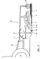
- a rotary cultivator 30 machine comprising a wheeled frame 1, in which a horizontally disposed shaft 2 is rotatably mounted.
- Figure 5 shows the shaft 2 being rotatably mounted with bearings 74 into side panels 72 of the wheeled frame 1.
- the cultivator 30 is towed by a conventional tractor 32 unit and powered from a power-take-off shaft 34 or hydraulic system of the tractor 32.
- the shaft 2 is provided with a plurality of soil-working members 3 that are spaced apart form one another both along the length of the shaft 2 and around the longitudinal axis of that shaft 2.
- a sifting means 4 which comprises a multiplicity of steel bars (not shown) fastened to strips of flexible material (not shown).
- the sifting means 4 travels in an upwardly direction and towards the rear of the machine 30 as shown by arrow B around revolving rollers 5, 6 and 7 of which at least one is driven.
- the sifting means 4 has agitators 8 to shake it and breaking means or scrubbers 9. Above the shaft 2 there is provided an extendable cover 10 and an adjustable shield 11 at attached to the cover 10 by a hinge 11a.
- the sifting means 4 is adjustable in terms of its speed of travel over the rollers 5, 6 and 7, its angle of inclination with respect to the ground surface, and in terms of its position in relation to shaft 2. It can also be adjusted such that the gaps in between the steel bars are either wider or narrower.
- the rotor 2 revolves in the direction of arrow C.
- the soil-working members 3 cut into the soil forming a cavity 36, thereby breaking it into a mixture of small particles 12, large particles 13 and stones 14. This mixture is thrown by the soil-working members 3 on to the sifting means 4, which moves in the direction of arrow B. Because larger particles 13 and stones 14 roll easily, they roll down the face of sifting means 4 into the cavity 36 excavated by the soil-working members 3. Some large soil particles 13 fall back on to the soil-working members 3 and are re-circulated around the shaft 2, and are broken up even further.
- the small soil particles 12 pass through the gaps on the sifting means 4 aided by the shaking action of the agitators 8, and fall on to the cavity 36 on top of the larger soil particles 13 and stones 14.
- a seeder unit 22, levelling means 21, packer roller 19 or other extra units (not shown) can be attached to the frame 1 in order to carry out a complete job in one pass.
- Beaches can be improved by laying the stones below the sand and producing a level surface.
- FIG. 2 there is shown a second embodiment of the cultivator 30 towed by a conventional tractor unit 32.
- FIG. 2 shows a machine substantially similar to that shown in Figure 1 and the same reference numbers are used to describe like parts.
- a share or removable plate 38 is provided at the lower end of the sifting means 4 which either directs soil particles 14 onto the sifting means 4 or back into the soil working members 3 where they are ground down further.
- a cross conveyor 16 consisting of a rubber conveyer belt 16b supported by rollers 16a.
- the sifting means 4 is shown having been adjusted so that the bottom roller 7 is almost touching the bottom of the cavity 36 excavated by the soil-working members 3.
- the small soil particles 12, large soil particles 13 and stones 14 are all thrown onto the sifting means 4.
- the small soil particles 12 pass through the gaps in the soil sifting means 4 and fall to the bottom of the cavity 36.
- a levelling means 21 levels the surface and a roller 19 consolidates the surface and helps support the machine or support wheels (not shown) run in the tractor wheelings.
- FIG. 3 there is shown a third embodiment of the cultivator 30 towed by a conventional tractor unit 32.
- FIG. 3 shows a machine substantially similar to that shown in Figure 1 .
- the same reference numbers are used to describe the parts.
- the third embodiment there are a series of ripper tines 20 arranged across the front of the machine 30 to loosen the existing track or surface material before the soil-working members 3 throw the small particles 12, large particles 13 and stones 14 onto the sifting means 4.
- the large particles 13 and stones 14 roll down the surface of the sifting means 4 into the cavity 36 excavated by the soil-working members 3.
- the small particles 12 pass through the gaps on the sifting means 4, either directly or with help from agitators 8 and the soil breaking means or scrubbers 9.
- a tank 17 containing binding agent 50, a pump 40, a sprayer 18 and a roller 19.
- the pump 40 pumps the binding agent 50 to the sprayer means 18 which then sprays the binding agent 21 on to the small particles 12 as they fall onto the cavity 36 on top of the large particles 13 and stones 14.
- a levelling bar 52 levels the surface and the roller 19 consolidates the surface as well as helping to support the machine.
- FIG. 4 there is shown a fourth embodiment of the cultivator 30 towed by a conventional tractor unit 32.
- the cultivator 38 is shown having a steel plate 62 located close to the bottom of the shaft 2 and soil working member 3.
- the steel plate 62 extends across the entire width of the cultivator 30 and is aimed upwardly away from the ground such that large particles 13, stones 14 and small particles 12 are all thrown onto the sifting means 4 thereby reducing the amount of particles 12,13,14 thrown thereunder.
- the position of the plate 62 makes it a suitable mounting point for short tines 60, which break up any hardpan, caused by the action of the rotating shaft 2 and soil working members 3.
- the plate 60 is adjustable for position with respect to the soil working members 3 and angle.
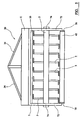
- FIG. 5 there is shown a rear view of the fourth embodiment of the cultivator 30 shown in Figure 4 .
- the steel plate 62 is shown attached by adjustable brackets 70, to two side panels 72 of the frame 1.
- FIG. 6 there is shown a fifth embodiment of the cultivator 30, towed by conventional tractor unit 32.
- the rotatable shaft 2 and soil working members 3 are shown rotating in the opposite direction to normal, ie. in the direction of arrow E shown in figure 5 instead of the direction of arrow C as shown in the other figures.
- the extendable cover 10 extends further downwards at the front of the cultivator 30 but not so far at the top of the cultivator 30.
- the adjustable shield 11 attached to the cover 10 by hinge 11a is arranged to allow the discharge of the material to a much higher level therefore striking the sifting means 4 for the top thereof, thereby allowing far improved separation. This is particularly useful when conditions dictate that the material is not easily separated otherwise.
- the rotary cultivator 30 reside in the effect manner in which the soils surface can be cultivated.
- the sifting means 4 is provided at an angle, which is adjustable so that larger particles, which do not pass through therethrough, are urged back to be recycled by the soil-working members.
- the scrubbers 9 also prevent particles, which are too large from bypassing the sifting means.
- the conveyer 16 transports larger stones which have bypassed the sifting means away from the cultivated soil patch where crops may be grown and into the tractor wheelings.
Landscapes
- Life Sciences & Earth Sciences (AREA)
- Engineering & Computer Science (AREA)
- Mechanical Engineering (AREA)
- Soil Sciences (AREA)
- Environmental Sciences (AREA)
- Soil Working Implements (AREA)
Claims (10)
- Drehkultivator, umfassend eine Erdreich-Aufbrecheinrichtung (2,3) zum Aufbrechen einer Lage von Erdreich, und eine bewegliche Erdreich-Sortiereinrichtung (4) zum Trennen des Erdreichs in unterschiedliche Partikelgrößen, wobei die Erdreich-Sortiereinrichtung (4) geneigt und in der geneigten Richtung aufwärts bewegbar oder in der geneigten Richtung abwärts bewegbar ist, und eine Lücke zwischen der Erdreich-Aufbrecheinrichtung (2,3) und der Erdreich-Sortiereinrichtung (4) verbleibt, derart, dass im Gebrauch Erdreichpartikel, die größer sind als eine vorbestimmte Größe, in einen Hohlraum zurückgeführt werden, der durch die Erdreich-Aufbrecheinrichtung (2,3) ausgehoben ist.
- Drehkultivator nach Anspruch 1, wobei der Neigungswinkel der Erdreich-Sortiereinrichtung (4) einstellbar ist.
- Drehkultivator nach Anspruch 1 oder 2, wobei die Erdreich-Sortiereinrichtung (4) eine Mehrzahl von Stangen umfasst, die von Gewebematerial getragen werden.
- Drehkultivator nach Anspruch 3, wobei die Breite von Lücken zwischen den Stangen einstellbar ist, derart, dass Partikelgrößen, die hindurchpassen, variiert werden können.
- Drehkultivator nach einem der vorhergehenden Ansprüche, wobei die Erdreich-Sortiereinrichtung (4) dazu ausgelegt ist, sich mit variablen Geschwindigkeiten zu drehen.
- Drehkultivator nach einem der Ansprüche 3 bis 5, wobei die Erdreich-Sortiereinrichtung (4) eine Schütteleinrichtung umfasst, die dazu ausgelegt ist, die Erdreich-Partikel durch die Lücken zwischen den Stangen zu schütteln.
- Drehkultivator nach einem der vorhergehenden Ansprüche, wobei der Drehkultivator eine Fördereinrichtung (16) umfasst, die dazu ausgelegt ist, Partikel an der Spitze der Erdreich-Sortiereinrichtung (4) seitlich weg zur Seite des Drehkultivators zu transferieren.
- Drehkultivator nach einem der vorhergehenden Ansprüche, wobei der Drehkultivator eine Einrichtung (17, 18) zur Bereitstellung eines Bindemittels für das kultivierte Erdreich umfasst.
- Drehkultivator nach einem der vorhergehenden Ansprüche, wobei die Position der Erdreich-Sortiereinrichtung (4) derart eingestellt ist, dass eine Lücke zwischen der Bodenoberfläche und der Erdreich-Sortiereinrichtung (4) verbleibt.
- Verfahren zum Kultivieren von Boden, umfassend die Verwendung eines Drehkultivators, der durch einen der Ansprüche 1 bis 9 definiert ist.
Applications Claiming Priority (5)
| Application Number | Priority Date | Filing Date | Title |
|---|---|---|---|
| GB0203374 | 2002-02-13 | ||
| GB0203374A GB0203374D0 (en) | 2002-02-13 | 2002-02-13 | Rotary cultivator |
| GB0215909 | 2002-07-09 | ||
| GB0215909A GB0215909D0 (en) | 2002-02-13 | 2002-07-09 | Rotary cultivator |
| PCT/GB2003/000639 WO2003067957A1 (en) | 2002-02-13 | 2003-02-13 | Rotary cultivator |
Publications (2)
| Publication Number | Publication Date |
|---|---|
| EP1473983A1 EP1473983A1 (de) | 2004-11-10 |
| EP1473983B1 true EP1473983B1 (de) | 2011-03-23 |
Family
ID=27736207
Family Applications (1)
| Application Number | Title | Priority Date | Filing Date |
|---|---|---|---|
| EP03704784A Expired - Lifetime EP1473983B1 (de) | 2002-02-13 | 2003-02-13 | Kreiselkultivator |
Country Status (3)
| Country | Link |
|---|---|
| EP (1) | EP1473983B1 (de) |
| AU (1) | AU2003207312A1 (de) |
| WO (1) | WO2003067957A1 (de) |
Cited By (1)
| Publication number | Priority date | Publication date | Assignee | Title |
|---|---|---|---|---|
| EP2946645A1 (de) | 2014-05-22 | 2015-11-25 | Grimme Landmaschinenfabrik GmbH & Co. KG | Verfahren und einrichtung zum behandeln von steinigen ackerböden |
Families Citing this family (6)
| Publication number | Priority date | Publication date | Assignee | Title |
|---|---|---|---|---|
| NL1025658C2 (nl) * | 2004-03-08 | 2005-09-12 | Jacob Jacobus Rodenburg | Werkwijze en inrichting voor het verwerken van een, uit of van de bodem of een grasmat vrijgemaakt, materiaal. |
| NL1027246C2 (nl) * | 2004-10-14 | 2006-04-19 | Kraaijeveld B V Geb | Inrichting voor het bewerken van een bodemlaag. |
| IT201700013866A1 (it) * | 2017-02-08 | 2018-08-08 | Consiglio Per La Ricerca In Agricoltura E Lanalisi Delleconomia Agraria | Metodo per la bonifica del terreno e macchina per la sua realizzazione |
| CN110959441B (zh) * | 2019-12-31 | 2024-08-27 | 滨州市农业机械化科学研究所 | 一种便捷多用途棉花封土机 |
| CN117546647B (zh) * | 2023-12-15 | 2025-01-14 | 中国农业科学院农业环境与可持续发展研究所 | 一种用于构建旱地海绵田的土壤打散装置 |
| CN119183700B (zh) * | 2024-10-10 | 2026-04-21 | 江苏省黄海农场有限公司 | 一种水稻育秧营养土取筛一体机 |
Family Cites Families (6)
| Publication number | Priority date | Publication date | Assignee | Title |
|---|---|---|---|---|
| US1276843A (en) * | 1915-10-08 | 1918-08-27 | Jesse S Wentworth | Process and machine for soil-tillage. |
| FR2204101A5 (de) * | 1972-10-23 | 1974-05-17 | Matrot Louis | |
| FR2291693A1 (fr) * | 1974-11-25 | 1976-06-18 | Jullien Jean | Engin de preparation des terres, notamment de culture, et de chapes de sols stabilises |
| US4345531A (en) * | 1980-04-15 | 1982-08-24 | Redl Narciss A | Apparatus and method for cultivating land |
| US4458763A (en) * | 1981-10-14 | 1984-07-10 | Koehring Company | Soil stabilizer machine with recycler screen |
| DE3535775A1 (de) * | 1985-10-11 | 1987-04-09 | Willy Ag Maschf | Aufbereitungsgeraet |
-
2003
- 2003-02-13 AU AU2003207312A patent/AU2003207312A1/en not_active Abandoned
- 2003-02-13 EP EP03704784A patent/EP1473983B1/de not_active Expired - Lifetime
- 2003-02-13 WO PCT/GB2003/000639 patent/WO2003067957A1/en not_active Ceased
Cited By (2)
| Publication number | Priority date | Publication date | Assignee | Title |
|---|---|---|---|---|
| EP2946645A1 (de) | 2014-05-22 | 2015-11-25 | Grimme Landmaschinenfabrik GmbH & Co. KG | Verfahren und einrichtung zum behandeln von steinigen ackerböden |
| DE102014007605A1 (de) | 2014-05-22 | 2015-12-17 | Grimme Landmaschinenfabrik Gmbh & Co. Kg | Verfahren und Einrichtung zum Behandeln von steinigen Ackerböden |
Also Published As
| Publication number | Publication date |
|---|---|
| WO2003067957A1 (en) | 2003-08-21 |
| EP1473983A1 (de) | 2004-11-10 |
| AU2003207312A1 (en) | 2003-09-04 |
Similar Documents
| Publication | Publication Date | Title |
|---|---|---|
| CN103917081B (zh) | 耕耘设备 | |
| KR101811850B1 (ko) | 경운 및 두둑 성형, 파종, 비닐 타공, 피복 및 복토, 진압을 순차적으로 한 번에 수행하는 농업기계 | |
| US5460229A (en) | Field aerator apparatus | |
| US3247812A (en) | Apparatus for conditioning lawns | |
| US6425445B1 (en) | Enhanced minimum tillage planter/renovator system | |
| US4436040A (en) | Landscaping and seeding apparatus | |
| US6192992B1 (en) | Machine for soil preparation | |
| US20080141914A1 (en) | Combined Agricultural Machine | |
| US4345531A (en) | Apparatus and method for cultivating land | |
| EP2436250A1 (de) | Bodenbearbeitungsvorrichtung und -verfahren | |
| CN113348823B (zh) | 一种平地、垄面两用木薯种植机 | |
| CN109068584B (zh) | 甘蔗移植机 | |
| NZ543197A (en) | An apparatus and method for furrow opening using a disc | |
| WO2003067957A1 (en) | Rotary cultivator | |
| KR20010049555A (ko) | 건답직파장치 | |
| JPS6181705A (ja) | 撹土、播種ベツド仕立てなどのための作業方法及び作業用機械の組合せ | |
| US6216796B1 (en) | Tractor rake attachment for light and medium grade soil work | |
| US20230020374A1 (en) | Apparatus for seeding | |
| JP2930476B2 (ja) | 不耕起直播機 | |
| JP2930475B2 (ja) | 不耕起乾田直播機 | |
| KR200422839Y1 (ko) | 자갈 매몰형 로터리 작업기 | |
| JP2523128Y2 (ja) | 耕耘装置における作溝機の配置構造 | |
| JP2514498Y2 (ja) | 不耕起ロ―タリにおける溝掘装置 | |
| RU130189U1 (ru) | Почвообрабатывающая фрезерная машина | |
| JP2534331Y2 (ja) | 不耕起播種における覆土装置 |
Legal Events
| Date | Code | Title | Description |
|---|---|---|---|
| PUAI | Public reference made under article 153(3) epc to a published international application that has entered the european phase |
Free format text: ORIGINAL CODE: 0009012 |
|
| 17P | Request for examination filed |
Effective date: 20040907 |
|
| AK | Designated contracting states |
Kind code of ref document: A1 Designated state(s): AT BE BG CH CY CZ DE DK EE ES FI FR GB GR HU IE IT LI LU MC NL PT SE SI SK TR |
|
| AX | Request for extension of the european patent |
Extension state: AL LT LV MK RO |
|
| GRAP | Despatch of communication of intention to grant a patent |
Free format text: ORIGINAL CODE: EPIDOSNIGR1 |
|
| GRAS | Grant fee paid |
Free format text: ORIGINAL CODE: EPIDOSNIGR3 |
|
| GRAA | (expected) grant |
Free format text: ORIGINAL CODE: 0009210 |
|
| AK | Designated contracting states |
Kind code of ref document: B1 Designated state(s): AT BE BG CH CY CZ DE DK EE ES FI FR GB GR HU IE IT LI LU MC NL PT SE SI SK TR |
|
| REG | Reference to a national code |
Ref country code: GB Ref legal event code: FG4D |
|
| REG | Reference to a national code |
Ref country code: CH Ref legal event code: EP |
|
| REG | Reference to a national code |
Ref country code: IE Ref legal event code: FG4D |
|
| REF | Corresponds to: |
Ref document number: 60336454 Country of ref document: DE Date of ref document: 20110505 Kind code of ref document: P |
|
| REG | Reference to a national code |
Ref country code: DE Ref legal event code: R096 Ref document number: 60336454 Country of ref document: DE Effective date: 20110505 |
|
| REG | Reference to a national code |
Ref country code: NL Ref legal event code: VDEP Effective date: 20110323 |
|
| PG25 | Lapsed in a contracting state [announced via postgrant information from national office to epo] |
Ref country code: GR Free format text: LAPSE BECAUSE OF FAILURE TO SUBMIT A TRANSLATION OF THE DESCRIPTION OR TO PAY THE FEE WITHIN THE PRESCRIBED TIME-LIMIT Effective date: 20110624 Ref country code: SE Free format text: LAPSE BECAUSE OF FAILURE TO SUBMIT A TRANSLATION OF THE DESCRIPTION OR TO PAY THE FEE WITHIN THE PRESCRIBED TIME-LIMIT Effective date: 20110323 |
|
| PG25 | Lapsed in a contracting state [announced via postgrant information from national office to epo] |
Ref country code: BG Free format text: LAPSE BECAUSE OF FAILURE TO SUBMIT A TRANSLATION OF THE DESCRIPTION OR TO PAY THE FEE WITHIN THE PRESCRIBED TIME-LIMIT Effective date: 20110623 Ref country code: AT Free format text: LAPSE BECAUSE OF FAILURE TO SUBMIT A TRANSLATION OF THE DESCRIPTION OR TO PAY THE FEE WITHIN THE PRESCRIBED TIME-LIMIT Effective date: 20110323 Ref country code: FI Free format text: LAPSE BECAUSE OF FAILURE TO SUBMIT A TRANSLATION OF THE DESCRIPTION OR TO PAY THE FEE WITHIN THE PRESCRIBED TIME-LIMIT Effective date: 20110323 Ref country code: CY Free format text: LAPSE BECAUSE OF FAILURE TO SUBMIT A TRANSLATION OF THE DESCRIPTION OR TO PAY THE FEE WITHIN THE PRESCRIBED TIME-LIMIT Effective date: 20110323 Ref country code: SI Free format text: LAPSE BECAUSE OF FAILURE TO SUBMIT A TRANSLATION OF THE DESCRIPTION OR TO PAY THE FEE WITHIN THE PRESCRIBED TIME-LIMIT Effective date: 20110323 |
|
| PG25 | Lapsed in a contracting state [announced via postgrant information from national office to epo] |
Ref country code: BE Free format text: LAPSE BECAUSE OF FAILURE TO SUBMIT A TRANSLATION OF THE DESCRIPTION OR TO PAY THE FEE WITHIN THE PRESCRIBED TIME-LIMIT Effective date: 20110323 |
|
| PG25 | Lapsed in a contracting state [announced via postgrant information from national office to epo] |
Ref country code: EE Free format text: LAPSE BECAUSE OF FAILURE TO SUBMIT A TRANSLATION OF THE DESCRIPTION OR TO PAY THE FEE WITHIN THE PRESCRIBED TIME-LIMIT Effective date: 20110323 Ref country code: PT Free format text: LAPSE BECAUSE OF FAILURE TO SUBMIT A TRANSLATION OF THE DESCRIPTION OR TO PAY THE FEE WITHIN THE PRESCRIBED TIME-LIMIT Effective date: 20110725 |
|
| PG25 | Lapsed in a contracting state [announced via postgrant information from national office to epo] |
Ref country code: ES Free format text: LAPSE BECAUSE OF FAILURE TO SUBMIT A TRANSLATION OF THE DESCRIPTION OR TO PAY THE FEE WITHIN THE PRESCRIBED TIME-LIMIT Effective date: 20110704 Ref country code: SK Free format text: LAPSE BECAUSE OF FAILURE TO SUBMIT A TRANSLATION OF THE DESCRIPTION OR TO PAY THE FEE WITHIN THE PRESCRIBED TIME-LIMIT Effective date: 20110323 Ref country code: CZ Free format text: LAPSE BECAUSE OF FAILURE TO SUBMIT A TRANSLATION OF THE DESCRIPTION OR TO PAY THE FEE WITHIN THE PRESCRIBED TIME-LIMIT Effective date: 20110323 |
|
| PG25 | Lapsed in a contracting state [announced via postgrant information from national office to epo] |
Ref country code: NL Free format text: LAPSE BECAUSE OF FAILURE TO SUBMIT A TRANSLATION OF THE DESCRIPTION OR TO PAY THE FEE WITHIN THE PRESCRIBED TIME-LIMIT Effective date: 20110323 |
|
| PLBE | No opposition filed within time limit |
Free format text: ORIGINAL CODE: 0009261 |
|
| STAA | Information on the status of an ep patent application or granted ep patent |
Free format text: STATUS: NO OPPOSITION FILED WITHIN TIME LIMIT |
|
| REG | Reference to a national code |
Ref country code: GB Ref legal event code: 732E Free format text: REGISTERED BETWEEN 20120105 AND 20120111 |
|
| 26N | No opposition filed |
Effective date: 20111227 |
|
| PG25 | Lapsed in a contracting state [announced via postgrant information from national office to epo] |
Ref country code: DK Free format text: LAPSE BECAUSE OF FAILURE TO SUBMIT A TRANSLATION OF THE DESCRIPTION OR TO PAY THE FEE WITHIN THE PRESCRIBED TIME-LIMIT Effective date: 20110323 |
|
| REG | Reference to a national code |
Ref country code: DE Ref legal event code: R082 Ref document number: 60336454 Country of ref document: DE Representative=s name: BETTEN & RESCH, DE |
|
| REG | Reference to a national code |
Ref country code: DE Ref legal event code: R097 Ref document number: 60336454 Country of ref document: DE Effective date: 20111227 |
|
| REG | Reference to a national code |
Ref country code: DE Ref legal event code: R082 Ref document number: 60336454 Country of ref document: DE Representative=s name: BETTEN & RESCH PATENT- UND RECHTSANWAELTE PART, DE Effective date: 20120314 Ref country code: DE Ref legal event code: R081 Ref document number: 60336454 Country of ref document: DE Owner name: MOATE, GEORGE, CLAYTON, GB Free format text: FORMER OWNER: GOSSOP, JOHN BRISTOW, GOOLE, NORTH HUMBERSIDE, GB Effective date: 20110224 Ref country code: DE Ref legal event code: R081 Ref document number: 60336454 Country of ref document: DE Owner name: MOATE, GEORGE, CLAYTON, GB Free format text: FORMER OWNER: GOSSOP, JOHN, NEAR GOOLE, NORTH HUMBERSIDE, GB Effective date: 20120314 Ref country code: DE Ref legal event code: R081 Ref document number: 60336454 Country of ref document: DE Owner name: MOATE, GEORGE, GB Free format text: FORMER OWNER: GOSSOP, JOHN, NEAR GOOLE, GB Effective date: 20120314 Ref country code: DE Ref legal event code: R081 Ref document number: 60336454 Country of ref document: DE Owner name: MOATE, GEORGE, GB Free format text: FORMER OWNER: GOSSOP, JOHN BRISTOW, GOOLE, GB Effective date: 20110224 Ref country code: DE Ref legal event code: R082 Ref document number: 60336454 Country of ref document: DE Representative=s name: PATENTANWAELTE BETTEN & RESCH, DE Effective date: 20120314 |
|
| PG25 | Lapsed in a contracting state [announced via postgrant information from national office to epo] |
Ref country code: IT Free format text: LAPSE BECAUSE OF FAILURE TO SUBMIT A TRANSLATION OF THE DESCRIPTION OR TO PAY THE FEE WITHIN THE PRESCRIBED TIME-LIMIT Effective date: 20110323 |
|
| REG | Reference to a national code |
Ref country code: GB Ref legal event code: 732E Free format text: REGISTERED BETWEEN 20120705 AND 20120711 |
|
| PG25 | Lapsed in a contracting state [announced via postgrant information from national office to epo] |
Ref country code: MC Free format text: LAPSE BECAUSE OF NON-PAYMENT OF DUE FEES Effective date: 20120229 |
|
| REG | Reference to a national code |
Ref country code: CH Ref legal event code: PL |
|
| PG25 | Lapsed in a contracting state [announced via postgrant information from national office to epo] |
Ref country code: LI Free format text: LAPSE BECAUSE OF NON-PAYMENT OF DUE FEES Effective date: 20120229 Ref country code: CH Free format text: LAPSE BECAUSE OF NON-PAYMENT OF DUE FEES Effective date: 20120229 |
|
| REG | Reference to a national code |
Ref country code: IE Ref legal event code: MM4A |
|
| PG25 | Lapsed in a contracting state [announced via postgrant information from national office to epo] |
Ref country code: IE Free format text: LAPSE BECAUSE OF NON-PAYMENT OF DUE FEES Effective date: 20120213 |
|
| PG25 | Lapsed in a contracting state [announced via postgrant information from national office to epo] |
Ref country code: TR Free format text: LAPSE BECAUSE OF FAILURE TO SUBMIT A TRANSLATION OF THE DESCRIPTION OR TO PAY THE FEE WITHIN THE PRESCRIBED TIME-LIMIT Effective date: 20110323 |
|
| PG25 | Lapsed in a contracting state [announced via postgrant information from national office to epo] |
Ref country code: LU Free format text: LAPSE BECAUSE OF NON-PAYMENT OF DUE FEES Effective date: 20120213 |
|
| PG25 | Lapsed in a contracting state [announced via postgrant information from national office to epo] |
Ref country code: HU Free format text: LAPSE BECAUSE OF FAILURE TO SUBMIT A TRANSLATION OF THE DESCRIPTION OR TO PAY THE FEE WITHIN THE PRESCRIBED TIME-LIMIT Effective date: 20030213 |
|
| REG | Reference to a national code |
Ref country code: FR Ref legal event code: PLFP Year of fee payment: 13 |
|
| REG | Reference to a national code |
Ref country code: FR Ref legal event code: PLFP Year of fee payment: 14 |
|
| REG | Reference to a national code |
Ref country code: FR Ref legal event code: PLFP Year of fee payment: 15 |
|
| PGFP | Annual fee paid to national office [announced via postgrant information from national office to epo] |
Ref country code: DE Payment date: 20170727 Year of fee payment: 15 Ref country code: GB Payment date: 20170711 Year of fee payment: 15 Ref country code: FR Payment date: 20170714 Year of fee payment: 15 |
|
| REG | Reference to a national code |
Ref country code: DE Ref legal event code: R119 Ref document number: 60336454 Country of ref document: DE |
|
| GBPC | Gb: european patent ceased through non-payment of renewal fee |
Effective date: 20180213 |
|
| REG | Reference to a national code |
Ref country code: FR Ref legal event code: ST Effective date: 20181031 |
|
| PG25 | Lapsed in a contracting state [announced via postgrant information from national office to epo] |
Ref country code: DE Free format text: LAPSE BECAUSE OF NON-PAYMENT OF DUE FEES Effective date: 20180901 |
|
| PG25 | Lapsed in a contracting state [announced via postgrant information from national office to epo] |
Ref country code: FR Free format text: LAPSE BECAUSE OF NON-PAYMENT OF DUE FEES Effective date: 20180228 Ref country code: GB Free format text: LAPSE BECAUSE OF NON-PAYMENT OF DUE FEES Effective date: 20180213 |