EP1473163A1 - Ink-jet printhead package - Google Patents
Ink-jet printhead package Download PDFInfo
- Publication number
- EP1473163A1 EP1473163A1 EP04251413A EP04251413A EP1473163A1 EP 1473163 A1 EP1473163 A1 EP 1473163A1 EP 04251413 A EP04251413 A EP 04251413A EP 04251413 A EP04251413 A EP 04251413A EP 1473163 A1 EP1473163 A1 EP 1473163A1
- Authority
- EP
- European Patent Office
- Prior art keywords
- ink
- package
- frame
- ink supply
- printhead chip
- Prior art date
- Legal status (The legal status is an assumption and is not a legal conclusion. Google has not performed a legal analysis and makes no representation as to the accuracy of the status listed.)
- Granted
Links
Images



Classifications
-
- B—PERFORMING OPERATIONS; TRANSPORTING
- B41—PRINTING; LINING MACHINES; TYPEWRITERS; STAMPS
- B41J—TYPEWRITERS; SELECTIVE PRINTING MECHANISMS, i.e. MECHANISMS PRINTING OTHERWISE THAN FROM A FORME; CORRECTION OF TYPOGRAPHICAL ERRORS
- B41J2/00—Typewriters or selective printing mechanisms characterised by the printing or marking process for which they are designed
- B41J2/22—Typewriters or selective printing mechanisms characterised by the printing or marking process for which they are designed characterised by selective application of impact or pressure on a printing material or impression-transfer material
- B41J2/23—Typewriters or selective printing mechanisms characterised by the printing or marking process for which they are designed characterised by selective application of impact or pressure on a printing material or impression-transfer material using print wires
- B41J2/235—Print head assemblies
-
- B—PERFORMING OPERATIONS; TRANSPORTING
- B41—PRINTING; LINING MACHINES; TYPEWRITERS; STAMPS
- B41J—TYPEWRITERS; SELECTIVE PRINTING MECHANISMS, i.e. MECHANISMS PRINTING OTHERWISE THAN FROM A FORME; CORRECTION OF TYPOGRAPHICAL ERRORS
- B41J2/00—Typewriters or selective printing mechanisms characterised by the printing or marking process for which they are designed
- B41J2/005—Typewriters or selective printing mechanisms characterised by the printing or marking process for which they are designed characterised by bringing liquid or particles selectively into contact with a printing material
- B41J2/01—Ink jet
- B41J2/135—Nozzles
- B41J2/145—Arrangement thereof
-
- B—PERFORMING OPERATIONS; TRANSPORTING
- B41—PRINTING; LINING MACHINES; TYPEWRITERS; STAMPS
- B41J—TYPEWRITERS; SELECTIVE PRINTING MECHANISMS, i.e. MECHANISMS PRINTING OTHERWISE THAN FROM A FORME; CORRECTION OF TYPOGRAPHICAL ERRORS
- B41J2/00—Typewriters or selective printing mechanisms characterised by the printing or marking process for which they are designed
- B41J2/005—Typewriters or selective printing mechanisms characterised by the printing or marking process for which they are designed characterised by bringing liquid or particles selectively into contact with a printing material
- B41J2/01—Ink jet
- B41J2/135—Nozzles
- B41J2/14—Structure thereof only for on-demand ink jet heads
- B41J2/14201—Structure of print heads with piezoelectric elements
- B41J2/14233—Structure of print heads with piezoelectric elements of film type, deformed by bending and disposed on a diaphragm
-
- B—PERFORMING OPERATIONS; TRANSPORTING
- B41—PRINTING; LINING MACHINES; TYPEWRITERS; STAMPS
- B41J—TYPEWRITERS; SELECTIVE PRINTING MECHANISMS, i.e. MECHANISMS PRINTING OTHERWISE THAN FROM A FORME; CORRECTION OF TYPOGRAPHICAL ERRORS
- B41J2/00—Typewriters or selective printing mechanisms characterised by the printing or marking process for which they are designed
- B41J2/005—Typewriters or selective printing mechanisms characterised by the printing or marking process for which they are designed characterised by bringing liquid or particles selectively into contact with a printing material
- B41J2/01—Ink jet
- B41J2/135—Nozzles
- B41J2/14—Structure thereof only for on-demand ink jet heads
- B41J2002/14362—Assembling elements of heads
-
- B—PERFORMING OPERATIONS; TRANSPORTING
- B41—PRINTING; LINING MACHINES; TYPEWRITERS; STAMPS
- B41J—TYPEWRITERS; SELECTIVE PRINTING MECHANISMS, i.e. MECHANISMS PRINTING OTHERWISE THAN FROM A FORME; CORRECTION OF TYPOGRAPHICAL ERRORS
- B41J2/00—Typewriters or selective printing mechanisms characterised by the printing or marking process for which they are designed
- B41J2/005—Typewriters or selective printing mechanisms characterised by the printing or marking process for which they are designed characterised by bringing liquid or particles selectively into contact with a printing material
- B41J2/01—Ink jet
- B41J2/135—Nozzles
- B41J2/14—Structure thereof only for on-demand ink jet heads
- B41J2002/14491—Electrical connection
Definitions
- the present invention thus provides an ink-jet printhead package having a simple structure in which, due to the absence of a head cover, a printhead is easily wiped.
- a support surface 132 that contacts and supports the printhead chip 300 is formed around inner edges of the groove 130, that is, around the perimeter of the hollow 110 and the perimeter of the ink supply hole 120.
- the support surface 132 protrudes from a bottom surface of the groove 130 to a predetermined height and forms a step S.
- the reservoir 321 that is connected to the ink induction hole 311 is formed along the length of the middle substrate 320 to a predetermined depth.
- a plurality of restrictors 322 that connect the reservoir 321 to one end of each of the ink chambers 312 are formed to be shallower than the reservoir 321.
- a plurality of dampers 323 that are vertically perforated in positions corresponding to the other end of the ink chambers 312 are formed on the middle substrate 320.
Landscapes
- Particle Formation And Scattering Control In Inkjet Printers (AREA)
- Ink Jet (AREA)
Abstract
Description
- The present invention relates to an ink-jet printhead package, and more particularly, to an ink-jet printhead package having a simple structure in which a printhead is easily wiped.
- Typically, ink-jet printheads are devices for printing a predetermined color image by ejecting a small volume of droplet of printing ink at a desired position on a recording sheet or textile etc. Ink-jet printheads are largely categorized into two types depending on ink droplet ejection mechanism: a thermally driven ink-jet printhead in which a heat source is employed to form and expand bubbles in ink causing ink droplets to be ejected, and a piezoelectrically driven ink-jet printhead in which a piezolectric crystal bends to exert pressure on ink causing ink droplets to be expelled.
- Ink-jet printheads are typically manufactured in a chip shape using various methods, including a semiconductor manufacturing process. And a packaging is required to mount the manufactured printhead chip in a printer.
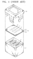
- FIG. 1 shows a conventional ink-jet printhead package. Referring to FIG. 1, the conventional ink-jet printhead package includes a
passage unit 16 comprising anozzle plate 13 on which a plurality ofnozzles 11 are arranged in rows, apassage formation plate 14 on which a plurality of pressure chambers corresponding to each of the plurality ofnozzles 11 are formed, and anelastic plate 15 which transfers vibration of apiezoelectric actuator 12 that is fixed in acasing 17 to change the volumes of the pressure chambers. Thepassage unit 16 is fixed in thecasing 17 by ahead cover 19 which has a window for exposing thenozzles 11. - In the conventional ink-jet printhead package, when some of the ink droplets ejected from through the
nozzles 11 remain on the surface of thenozzle plate 13, the ink droplets remaining on the surface of thenozzle plate 13 mix with ink of other colors, or an ejection direction of the ink droplets is changed, resulting in a lower printing quality. Thus, a wiping blade is usually used to remove the ink remaining on the surface of thenozzle plate 13. When the printhead package moves in a reciprocating motion, the wiping blade comes in contact with the surface of thenozzle plate 13 and wipes the ink which remains behind. - However, in the conventional ink-jet printhead package, the entire periphery of the surface of the
nozzle plate 13 is covered with thehead cover 19, and a wiping blade that can be somewhat elastically-transformed cannot be closely attached to a region that is near thehead cover 19. Thus, the ink remaining on thenozzle plate 13 cannot be sufficiently removed. - As such, ink-jet printhead packages which prevent the above problems have been developed. An example of such ink-jet printhead packages is shown in FIGS. 2 through 4. The printhead packages shown in FIGS. 2 through 4 are disclosed in U.S. Patent No. 6,206,499.
- The ink-jet printhead package shown in FIGS. 2 through 4 includes a
casing 32, apassage unit 34 comprising having anozzle plate 41 on which a plurality ofnozzles 43 are formed, and ahead cover 35 which fixes thepassage unit 34 in thecasing 32. - The
head cover 35 has foursidewalls 50, each of the foursidewalls 50 contacting sides of thecasing 32. Anoverlap portion 51, which covers part of the surface of thenozzle plate 41, is provided only on thesidewalls 50, which are perpendicular to a wiping direction (direction of arrow A). On the other hand, an overlap portion is not provided on thesidewalls 50 which are parallel to the wiping direction (direction of arrow A), so that a wipingspace 52 is formed. - In the conventional ink-jet printhead package having the above structure, as shown in FIGS. 3 and 4, when the surface of the
nozzle plate 41 is wiped with thewiping blade 56, thewiping blade 56 contacts the whole width of the surface of thenozzle plate 41, so that ink K remaining on the surface of thenozzle plate 41 can be easily removed. - However, in the aforementioned ink-jet printhead package, as shown in FIG. 4, the
overlap portion 51 is on thehead cover 35 in order to fix thepassage unit 34 in thecasing 32. Thus, ink can spread between thenozzle plate 41 and theoverlap portion 51 and may be scattered on an object to be printed on during a printing operation, resulting in a lower printing quality. In addition, a step is formed between the surface of thenozzle plate 41 and theoverlap portion 51. As a result, an unstable motion of thewiping blade 56 occurs. In addition, the ink left unremoved is stacked in a corner portion formed by the step. - According to an aspect of the present invention, there is provided an ink-jet printhead package, the ink-jet printhead package comprising: a frame, with a hollow therein that is vertically perforated, an ink supply hole therein, and a groove that surrounds the hollow and the ink supply hole is formed in a bottom surface of the frame; an adhesive coated inside the groove; and a printhead chip, which is adhered to the frame by the adhesive and ejects ink that is supplied through the ink supply hole through a plurality of nozzles.
- It is preferable that the adhesive is room temperature vulcanizing (RTV) silicon resin.
- Meanwhile, the adhesive includes RTV silicon resin that is coated inside the groove around the ink supply hole, and epoxy resin that is coated inside the groove around the hollow.
- It is also preferable that a support surface that contacts and supports the printhead chip may be formed around inner edges of the groove, and the support surface forms a step with the bottom surface of the frame.
- It is also preferable that the height of the step is not greater than a thickness of the printhead chip, and it is more preferable that the step is substantially the same as the thickness of the printhead chip so that a bottom surface of the printhead chip forms the same plane as the bottom surface of the frame.
- It is also preferable that the printhead chip includes a plurality of ink chambers which are filled by ink supplied through the ink supply hole, a plurality of nozzles which correspond to the plurality of ink chambers, and an actuator which provides a driving force by which ink inside the ink chambers is ejected through the nozzles.
- It is also preferable that a bracket, in which a printed circuit board is formed, is combined with an upper portion of the frame, and the printed circuit board and the printhead chip are electrically connected to each other by a flexible printed circuit, and an ink supply hose is connected to the ink supply hole. In this case, it is preferable that a nipple in which the ink supply hose is inserted, is installed in the ink supply hole.
- The above-described ink-jet printhead package according to the present invention need not include a head cover, such that the printhead chip is easily wiped and the structure of the ink-jet printhead package is simplified.
- The present invention thus provides an ink-jet printhead package having a simple structure in which, due to the absence of a head cover, a printhead is easily wiped.
- The above aspects and advantages of the present invention will become more apparent by describing in detail preferred embodiments thereof with reference to the attached drawings in which:
- FIG. 1 is an exploded perspective view of a conventional ink-jet printhead package;
- FIG. 2 is a perspective view of a conventional ink-jet printhead package;
- FIG. 3 is a cross-sectional view of a wiping blade from the front and a head cover shown in FIG. 2;
- FIG. 4 is a cross-sectional view of the wiping blade from the side and the head cover shown in FIG. 2;
- FIG. 5 is an exploded view of an ink-jet printhead package according to a preferred embodiment of the present invention;
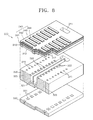
- FIG. 6 is an exploded view of a reverse side of the ink-jet printhead package according to the preferred embodiment of the present invention, shown in FIG. 5;
- FIG. 7 is a vertical cross-sectional view illustrating the ink-jet printhead package taken along line C-C' of FIG. 5;
- FIG. 8 is an exploded partial cross-sectional view of a printhead chip shown in FIG. 5; and
- FIG. 9 is a perspective view illustrating the ink-jet printhead package to which other elements are added.
-
- Hereinafter, the present invention will be described in detail by describing a preferred embodiment of the present invention with reference to the accompanying drawings. This invention may, however, be embodied in many different forms and should not be construed as being limited to the embodiments set forth herein. Same reference numerals denote elements having same functions, and the size and thickness of an element may be exaggerated for clarity.
- FIG. 5 is an exploded view of an ink-jet printhead package according to a preferred embodiment of the present invention, and FIG. 6 is an exploded view of a reverse side of the ink-jet printhead package according to the preferred embodiment of the present invention, shown in FIG. 5.
- Referring to FIGS. 5 and 6, the ink-jet printhead package according to the present invention includes a
frame 100 and aprinthead chip 300 that is adhered to theframe 100 by an adhesive 200. - The
frame 100 includes a hollow 110 that is vertically perforated and anink supply hole 120 that is adjacent to the hollow 110 and vertically perforated. Anipple 122 in which an ink supply hose (430 of FIG. 9) that will be described later is inserted, is installed in theink supply hole 120. Theframe 100 may be formed of plastics, and thenipple 122 may be formed of stainless steel. - A
groove 130 that surrounds the hollow 110 and theink supply hole 120 is formed to a predetermined depth on abottom surface 101 of theframe 100. The adhesive 200, by which theprinthead chip 300 is adhered to theframe 100, is coated inside thegroove 130. - A variety of kinds of adhesives that provide a high adhesion property and a high sealing characteristic may be used as the adhesive 200. In the preferred embodiment of the present invention, room temperature vulcanizing (RTV) silicon resin is used for the adhesive 200. The RTV silicon resin is highly adhesive and has a high sealing characteristic and an advantage of not needing a user to press or heat the adhesive 200 for vulcanization. In addition, the RTV silicon resin does not react to ink, does not deteriorate, and does not deteriorate ink.
- Also, both the RTV silicon resin and an epoxy resin may be used for the adhesive 200. The epoxy resin has a variety of vulcanizing mechanism which depend on its s type and is more adhesive than the RTV silicon resin. On the other hand, the epoxy resin reacts to ink. Thus, it is preferable that an RTV silicon resin that does not react to ink is coated on a peripheral region D of the
ink supply hole 120 that has a strong possibility of coming in contact with ink, that is, inside thegroove 130 around theink supply hole 120, and a more adhesive epoxy resin is coated inside thegroove 130 around the hollow 110 that has a lower possibility of coming in contact with ink. - FIG. 7 a vertical cross-sectional view illustrating the ink-jet printhead package taken along line C-C' of FIG. 5.
- Referring to FIG. 7, a
support surface 132 that contacts and supports theprinthead chip 300 is formed around inner edges of thegroove 130, that is, around the perimeter of the hollow 110 and the perimeter of theink supply hole 120. In this case, it is preferable that thesupport surface 132 protrudes from a bottom surface of thegroove 130 to a predetermined height and forms a step S. - Preferably, the height of the step S is not greater than a thickness T of the
printhead chip 300. In other words, the step S is formed to have a height which is less than or equal to the thickness T of theprinthead chip 300. In particular, when the step S has the same height as the thickness T of theprinthead chip 300, a bottom surface 301 (hereinafter, referred to as a nozzle surface) of theprinthead chip 300 lies in the same plane as abottom surface 101 of theframe 100. - The
printhead chip 300 ejects ink, which is supplied through anink induction hole 311 that is aligned with theink supply hole 120, through the plurality ofnozzles 331. As described above, theprinthead chip 300 is securely adhered to theframe 100 by the adhesive 200. - In this case, a process of adhering the
printhead chip 300 to theframe 100 is performed as follows. First, when theframe 100 is upside-down, that is, when thegroove 130 formed on thebottom surface 101 of theframe 100 faces upward, the adhesive 200, such as the RTV silicon resin or the epoxy resin, is coated inside thegroove 130. In this case, the adhesive 200 may be in a liquid state or paste state. Subsequently, theprinthead chip 300 is put on the adhesive 200 and is compressed in theframe 100 using a compression plate. In this case, it is preferable that theframe 100 is returned to its original position so that theprinthead chip 300 faces downward. This is because, even when the adhesive 200 does not sufficiently fill in thegroove 130, a contact surface between theprinthead chip 300 and theframe 100, on which the adhesive 200 in a liquid state or paste state is placed under thegroove 130, can be sealed more securely. After a predetermined time passes in this state, the adhesive 200 is vulcanized, and theprinthead chip 300 is securely adhered to theframe 100. When the compression plate is removed after the adhesive 200 is vulcanized, the process of adhering theprinthead chip 300 to theframe 100 is completed. - As described above, the ink-jet printhead package does not include a conventional head cover. In addition. the
nozzle surface 301 of theprinthead chip 300 is in the same plane as thebottom surface 101 of theframe 100. As such, a wiping blade contacts theentire nozzle surface 301 of theprinthead chip 300. Thus, thenozzle surface 301 is easily wiped such that foreign substances and ink that remain on thenozzle surface 301 are better removed. Further, elements of the printhead package are reduced, such that the ink-jet printhead package has a simplified structure, the size thereof is reduced and costs are reduced. - An exploded view of the
printhead chip 300 in FIG. 5 is shown in FIG. 8. Referring to FIG. 8, theprinthead chip 300 includes a plurality ofink chambers 312 which are filled by ink supplied through theink supply hole 120, a plurality ofnozzles 331 which correspond to the plurality ofink chambers 312, and anactuator 340 which provides a driving force by which ink inside theink chambers 312 is ejected through thenozzles 331. In a preferred embodiment of the present invention, a piezoelectric type actuator is used as theactuator 340. - Specifically, the
printhead chip 300 may be formed by stacking threesubstrates substrates piezoelectric actuator 340 is formed on theupper substrate 310. Theink induction hole 311 which aligns with theink supply hole 120, and the plurality ofink chambers 312 are formed on theupper substrate 310. Theink chambers 312 are arranged in two rows on both sides of areservoir 321 that is formed on themiddle substrate 320. - The
piezoelectric actuator 340 is formed on theupper substrate 310. Thepiezoelectric actuator 340 includes avibration plate 341 located on theink chambers 312, and apiezoelectric body 343 which is located on thevibration plate 341 and vibrates thevibration plate 341. Alower electrode 342, which serves as a common electrode, is located under thepiezoelectric body 343, and anupper electrode 344, which serves as a driving electrode for applying a voltage to thepiezoelectric body 343, is located on thepiezoelectric body 343. - The
reservoir 321 that is connected to theink induction hole 311 is formed along the length of themiddle substrate 320 to a predetermined depth. In addition, a plurality ofrestrictors 322 that connect thereservoir 321 to one end of each of theink chambers 312 are formed to be shallower than thereservoir 321. A plurality ofdampers 323 that are vertically perforated in positions corresponding to the other end of theink chambers 312 are formed on themiddle substrate 320. - The plurality of
nozzles 331 that are perforated in a position corresponding to thedampers 323 are formed on thelower substrate 330. - The three
substrates printhead chip 300. - The operation of the
printhead chip 300 having the above structure will be described as below. Ink flowing to thereservoir 321 through theink supply hole 120 and theink induction hole 311 from an ink cartridge (not shown) is supplied to theink chambers 312 through therestrictors 322. If theink chambers 312 are filled with ink when a voltage is applied to thepiezoelectric body 343 through theupper electrode 344 of thepiezoelectric actuator 340, thepiezoelectric body 343 is deformed. As such, thevibration plate 341 is bent downward. Due to the deformation of thevibration plate 341, the volumes of theink chambers 312 are reduced. Due to a pressure increase in theink chambers 312 caused by the reduction in the volumes of theink chambers 312, ink in theink chamber 312 passes through thedampers 323 and is ejected to the outside through thenozzles 331. Subsequently, when the voltage that has been applied to thepiezoelectric body 343 of thepiezoelectric actuator 340 is cut off, thepiezoelectric body 343 is returned to its original shape. As such, thevibration plate 341 is returned to its original shape, and the volumes of theink chambers 312 increase. Due to the reduction in the pressure inside theink chambers 312, ink that is stored in thereservoir 321 flows to theink chamber 312 through therestrictors 322, and theink chambers 312 are filled with ink. - An ink-jet printhead package to which other elements are added is shown in FIG. 9.
- Referring to FIG. 9, a
bracket 410 is combined with an upper portion of theframe 100 to which theprinthead chip 300 is adhered. Combination of theframe 100 and thebracket 410 may be performed using ascrew 401. A printed circuit board (PCB) 412 which drives theprinthead chip 300, is installed in thebracket 410. - The
PCB 412 and theprinthead chip 300 are electrically connected to each other by a flexible printed circuit (FPC) 420. TheFPC 420 may be connected to thePCB 412 and theprinthead chip 300 through the hollow 110 of theframe 100. A plurality ofconnectors 414 for connecting theFPC 420 are provided on thePCB 412. - One end of an
ink supply hose 430 is connected to theink supply hole 120 of theframe 110. The other end of theink supply hose 430 is connected to an ink container mounted in the printer. As described above, anipple 122 in which theink supply hose 430 is inserted, may be installed in theink supply hole 120. - Experimental results of testing the adhesive properties and the sealing characteristics of the printhead chip with respect to the ink-jet printhead package are as follows. When the printhead chip has been driven at a temperature of 70 °C for about one hour, it is ascertained that ink does not leak. When ink is supplied to the printhead chip under a pressure of 8 psi, it is ascertained that there is no abnormality in the sealing. It is also ascertained that there is no abnormality in the adhering condition of the printhead chip after the experiment is done. It is concluded from the experimental results that the components of the ink-jet printhead package are sufficiently adhesive, and the ink-jet printhead package is sufficiently sealed, even when the printhead chip is adhered to the frame using the adhesive without the head cover according to the preferred embodiment of the present invention.
- A
CCD camera 440 is used when characteristics of ink ejection are measured for theprinthead chip 300, as shown in FIG. 9. In a conventional ink-jet printhead package, since theCCD camera 440 is covered by the head cover, there is a difficulty in measuring an ink ejection speed immediately after the ink leaves the nozzles. However, since the printhead package according to the preferred embodiment of the present invention does not include a head cover and thenozzle surface 301 of theprinthead chip 300 lies in the same plane as thebottom surface 101 of theframe 100, it becomes easy to measure the ink ejection speed immediately after the ink leaves thenozzles 331 using theCCD camera 440. - As described above, in the ink-jet printhead package according to the preferred embodiment of the present invention, a conventional head cover is not provided, such that the nozzle surface of the printhead chip lies in the same plane as the bottom surface of the frame. As such, the nozzle surface of the printhead chip is easily wiped using the wiping blade, and foreign substances and ink that remain on the nozzle plate are better removed. Thus, the problem with conventional ink-jet printhead packages, that ink is spread between the head cover and the frame does not occur.
- In addition, the number of elements of the printhead package is reduced, such that the structure of the printhead package is simplified, the size thereof is reduced and costs are reduced.
- In addition, since there is no head cover and the nozzle surface of the printhead chip lies in the same plane as the bottom surface of the frame, the ejection characteristics of ink droplets through the nozzles are easily measured.
- While this invention has been particularly shown and described with reference to preferred embodiments thereof, it will be understood by those skilled in the art that various changes in form and details may be made therein without departing from the scope of the invention as defined by the appended claims. For example, although the present invention is shown and described in an ink-jet printhead package having a piezoelectric type printhead chip, the present invention is not limited to this, but may be used in a printhead package having an electro-thermal transducer type printhead chip. In addition, although the RTV silicon resin and the epoxy resin are used as the adhesive by which the printhead chip is adhered to the frame, different types of adhesives having an adhesion property and a sealing characteristic can be used. Accordingly, it is intended that the scope of the invention be defined by the claims appended hereto.
Claims (11)
- An ink-jet printhead package comprising:a frame, with a hollow therein that is vertically perforated, an ink supply hole therein, and a groove that surrounds the hollow and the ink supply hole is formed in a bottom surface of the frame;an adhesive coated inside the groove; anda printhead chip, which is adhered to the frame by the adhesive and arranged to eject ink that is supplied through the ink supply hole through a plurality of nozzles.
- The package of claim 1, wherein the adhesive is room temperature vulcanizing silicon resin.
- The package of claim 1, wherein the adhesive includes room temperature vulcanizing silicon resin that is coated inside the groove around the ink supply hole, and epoxy resin that is coated inside the groove around the hollow.
- The package of any one of the preceding claims, wherein a support surface that contacts and supports the printhead chip may be formed around inner edges of the groove, and the support surface forms a step with the bottom surface of the frame.
- The package of claim 4, wherein the height of the step is not greater than a thickness of the printhead chip.
- The package of claim 4 or 5, wherein the height of the step is substantially the same as the thickness of the printhead chip so that a bottom surface of the printhead chip forms the same plane as the bottom surface of the frame.
- The package of any one of the preceding claims, wherein the printhead chip includes a plurality of ink chambers which are filled by ink supplied through the ink supply hole, a plurality of nozzles which correspond to the plurality of ink chambers, and an actuator which provides a driving force by which ink inside the ink chambers is ejected through the nozzles.
- The package of claim 7, wherein the actuator is a piezoelectric actuator, which includes a vibration plate located on the ink chambers, and a piezoelectric body which is located on the vibration plate and vibrates the vibration plate.
- The package of claim 7 or 8, wherein the printhead chip comprises:an upper substrate in which the ink chambers are formed and an ink induction hole corresponding to the ink supply hole is formed;a middle substrate in which a reservoir that connects the ink induction hole to the ink chambers and dampers that connect the ink chambers to the nozzles are formed;a lower substrate in which the plurality of nozzles are formed; andthe piezoelectric actuator that is formed on the upper substrate.
- The package of any one of the preceding claims, wherein a bracket, in which a printed circuit board is formed, is combined with an upper portion of the frame, and the printed circuit board and the printhead chip are electrically connected to each other by a flexible printed circuit, and an ink supply hose is connected to the ink supply hole.
- The package of claim 10, wherein a nipple in which the ink supply hose is inserted, is installed in the ink supply hole.
Applications Claiming Priority (2)
| Application Number | Priority Date | Filing Date | Title |
|---|---|---|---|
| KR2003028002 | 2003-05-01 | ||
| KR10-2003-0028002A KR100506093B1 (en) | 2003-05-01 | 2003-05-01 | Ink-jet printhead package |
Publications (2)
| Publication Number | Publication Date |
|---|---|
| EP1473163A1 true EP1473163A1 (en) | 2004-11-03 |
| EP1473163B1 EP1473163B1 (en) | 2009-09-16 |
Family
ID=32985947
Family Applications (1)
| Application Number | Title | Priority Date | Filing Date |
|---|---|---|---|
| EP04251413A Expired - Lifetime EP1473163B1 (en) | 2003-05-01 | 2004-03-11 | Ink-jet printhead package |
Country Status (6)
| Country | Link |
|---|---|
| US (1) | US7185968B2 (en) |
| EP (1) | EP1473163B1 (en) |
| JP (1) | JP4353833B2 (en) |
| KR (1) | KR100506093B1 (en) |
| CN (1) | CN1313272C (en) |
| DE (1) | DE602004023150D1 (en) |
Cited By (3)
| Publication number | Priority date | Publication date | Assignee | Title |
|---|---|---|---|---|
| EP1827835A4 (en) * | 2004-12-03 | 2009-12-23 | Fujifilm Dimatix Inc | Printheads and systems using printheads |
| CN110494853A (en) * | 2017-01-26 | 2019-11-22 | 维纳米技术公司 | Chip-embedded printed circuit board and method of manufacture |
| TWI722868B (en) * | 2020-04-14 | 2021-03-21 | 元力智庫有限公司 | Quick release nozzle |
Families Citing this family (22)
| Publication number | Priority date | Publication date | Assignee | Title |
|---|---|---|---|---|
| JP2006341228A (en) * | 2005-06-10 | 2006-12-21 | Shibaura Mechatronics Corp | Coating device |
| US7559620B2 (en) * | 2006-09-27 | 2009-07-14 | Eastman Kodak Company | Printhead assembly having replaceable printhead |
| US8523323B2 (en) * | 2008-05-23 | 2013-09-03 | Fujifilm Corporation | Method and apparatus for mounting a fluid ejection module |
| JP2010162741A (en) * | 2009-01-14 | 2010-07-29 | Fujifilm Corp | Inkjet head, method for manufacturing the same, and inkjet recording apparatus |
| JP5148555B2 (en) * | 2009-05-11 | 2013-02-20 | 東芝テック株式会社 | Inkjet head |
| JP5532227B2 (en) * | 2010-03-25 | 2014-06-25 | セイコーエプソン株式会社 | Liquid ejecting head and liquid ejecting apparatus |
| CN102451798A (en) * | 2010-10-14 | 2012-05-16 | 研能科技股份有限公司 | Single-hole nozzle device |
| JP2012187717A (en) * | 2011-03-08 | 2012-10-04 | Toshiba Tec Corp | Inkjet head |
| KR20130039006A (en) * | 2011-10-11 | 2013-04-19 | 삼성전기주식회사 | Inkjet print head assembly |
| US8814328B2 (en) * | 2011-12-13 | 2014-08-26 | Xerox Corporation | Polymer film as an interstitial fill for PZT printhead fabrication |
| JP6061533B2 (en) * | 2012-07-27 | 2017-01-18 | キヤノン株式会社 | Liquid discharge head and manufacturing method thereof |
| US10632752B2 (en) | 2013-02-28 | 2020-04-28 | Hewlett-Packard Development Company, L.P. | Printed circuit board fluid flow structure and method for making a printed circuit board fluid flow structure |
| KR101827070B1 (en) | 2013-02-28 | 2018-02-07 | 휴렛-팩커드 디벨롭먼트 컴퍼니, 엘.피. | Molding a fluid flow structure |
| US10821729B2 (en) | 2013-02-28 | 2020-11-03 | Hewlett-Packard Development Company, L.P. | Transfer molded fluid flow structure |
| EP3296113B1 (en) | 2013-02-28 | 2019-08-28 | Hewlett-Packard Development Company, L.P. | Molded print bar |
| CN105377560B (en) * | 2013-02-28 | 2018-01-19 | 惠普发展公司,有限责任合伙企业 | molded fluid flow structure |
| US10029467B2 (en) * | 2013-02-28 | 2018-07-24 | Hewlett-Packard Development Company, L.P. | Molded printhead |
| US9724920B2 (en) | 2013-03-20 | 2017-08-08 | Hewlett-Packard Development Company, L.P. | Molded die slivers with exposed front and back surfaces |
| JP6350792B2 (en) * | 2013-12-09 | 2018-07-04 | セイコーエプソン株式会社 | Liquid ejecting apparatus and liquid ejecting head unit |
| JP5980268B2 (en) | 2014-05-30 | 2016-08-31 | キヤノン株式会社 | Liquid discharge head and method of manufacturing liquid discharge head |
| JP2017105026A (en) * | 2015-12-08 | 2017-06-15 | エスアイアイ・プリンテック株式会社 | Liquid jet head, liquid jet recording device and method for production of liquid jet head |
| CN109130169B (en) * | 2018-09-03 | 2020-07-17 | 西安增材制造国家研究院有限公司 | MEMS printing head package |
Citations (7)
| Publication number | Priority date | Publication date | Assignee | Title |
|---|---|---|---|---|
| US4680859A (en) * | 1985-12-06 | 1987-07-21 | Hewlett-Packard Company | Thermal ink jet print head method of manufacture |
| EP0666174A2 (en) * | 1994-02-04 | 1995-08-09 | Hewlett-Packard Company | Unit print head for ink jet printing |
| US5606352A (en) * | 1991-06-14 | 1997-02-25 | Canon Kabushiki Kaisha | Ink jet cartridge having a can filtered ink supply member and ink jet apparatus including the same |
| EP1034931A1 (en) * | 1995-11-10 | 2000-09-13 | Seiko Epson Corporation | Ink jet type recording head |
| US6206499B1 (en) | 1998-10-19 | 2001-03-27 | Seiko Epson Corporation | Ink-jet recording head |
| US6244696B1 (en) * | 1999-04-30 | 2001-06-12 | Hewlett-Packard Company | Inkjet print cartridge design for decreasing ink shorts by using an elevated substrate support surface to increase adhesive sealing of the printhead from ink penetration |
| US6322200B1 (en) * | 1999-10-29 | 2001-11-27 | Hewlett-Packard Company | Decoupled nozzle plate and electrical flexible circuit for an inkjet print cartridge |
Family Cites Families (6)
| Publication number | Priority date | Publication date | Assignee | Title |
|---|---|---|---|---|
| JP2980451B2 (en) * | 1992-04-22 | 1999-11-22 | キヤノン株式会社 | INK JET PRINT HEAD, METHOD FOR MANUFACTURING THE SAME, AND A RECORDING APPARATUS HAVING THE INK JET PRINT HEAD |
| JP3144949B2 (en) * | 1992-05-27 | 2001-03-12 | 日本碍子株式会社 | Piezoelectric / electrostrictive actuator |
| JP3327314B2 (en) * | 1995-04-05 | 2002-09-24 | セイコーエプソン株式会社 | Ink jet recording head |
| JP3215789B2 (en) | 1995-12-21 | 2001-10-09 | シチズン時計株式会社 | Inkjet recording head |
| US6257703B1 (en) * | 1996-07-31 | 2001-07-10 | Canon Kabushiki Kaisha | Ink jet recording head |
| US6679595B2 (en) * | 2001-02-08 | 2004-01-20 | Brother Kogyo Kabushiki Kaisha | Ink jet recording apparatus |
-
2003
- 2003-05-01 KR KR10-2003-0028002A patent/KR100506093B1/en not_active Expired - Fee Related
-
2004
- 2004-03-02 CN CNB2004100073795A patent/CN1313272C/en not_active Expired - Fee Related
- 2004-03-11 DE DE602004023150T patent/DE602004023150D1/en not_active Expired - Lifetime
- 2004-03-11 EP EP04251413A patent/EP1473163B1/en not_active Expired - Lifetime
- 2004-03-15 JP JP2004073540A patent/JP4353833B2/en not_active Expired - Fee Related
- 2004-04-28 US US10/833,039 patent/US7185968B2/en not_active Expired - Fee Related
Patent Citations (7)
| Publication number | Priority date | Publication date | Assignee | Title |
|---|---|---|---|---|
| US4680859A (en) * | 1985-12-06 | 1987-07-21 | Hewlett-Packard Company | Thermal ink jet print head method of manufacture |
| US5606352A (en) * | 1991-06-14 | 1997-02-25 | Canon Kabushiki Kaisha | Ink jet cartridge having a can filtered ink supply member and ink jet apparatus including the same |
| EP0666174A2 (en) * | 1994-02-04 | 1995-08-09 | Hewlett-Packard Company | Unit print head for ink jet printing |
| EP1034931A1 (en) * | 1995-11-10 | 2000-09-13 | Seiko Epson Corporation | Ink jet type recording head |
| US6206499B1 (en) | 1998-10-19 | 2001-03-27 | Seiko Epson Corporation | Ink-jet recording head |
| US6244696B1 (en) * | 1999-04-30 | 2001-06-12 | Hewlett-Packard Company | Inkjet print cartridge design for decreasing ink shorts by using an elevated substrate support surface to increase adhesive sealing of the printhead from ink penetration |
| US6322200B1 (en) * | 1999-10-29 | 2001-11-27 | Hewlett-Packard Company | Decoupled nozzle plate and electrical flexible circuit for an inkjet print cartridge |
Cited By (3)
| Publication number | Priority date | Publication date | Assignee | Title |
|---|---|---|---|---|
| EP1827835A4 (en) * | 2004-12-03 | 2009-12-23 | Fujifilm Dimatix Inc | Printheads and systems using printheads |
| CN110494853A (en) * | 2017-01-26 | 2019-11-22 | 维纳米技术公司 | Chip-embedded printed circuit board and method of manufacture |
| TWI722868B (en) * | 2020-04-14 | 2021-03-21 | 元力智庫有限公司 | Quick release nozzle |
Also Published As
| Publication number | Publication date |
|---|---|
| JP2004330774A (en) | 2004-11-25 |
| KR100506093B1 (en) | 2005-08-04 |
| CN1541839A (en) | 2004-11-03 |
| US20050012775A1 (en) | 2005-01-20 |
| JP4353833B2 (en) | 2009-10-28 |
| CN1313272C (en) | 2007-05-02 |
| EP1473163B1 (en) | 2009-09-16 |
| DE602004023150D1 (en) | 2009-10-29 |
| KR20040094067A (en) | 2004-11-09 |
| US7185968B2 (en) | 2007-03-06 |
Similar Documents
| Publication | Publication Date | Title |
|---|---|---|
| EP1473163B1 (en) | Ink-jet printhead package | |
| CN100478185C (en) | Container having liquid detecting function, and sensor unit | |
| EP3456541B1 (en) | Liquid ejecting apparatus and control method of liquid ejecting apparatus | |
| CN104842663B (en) | Liquid discharge device and discharge abnormality detection method | |
| US7771006B2 (en) | Liquid ejecting apparatus and capping member used in the same | |
| EP3375612A1 (en) | Liquid ejection head and liquid ejection apparatus | |
| JP6375641B2 (en) | Liquid ejecting head and liquid ejecting apparatus | |
| CN101152786B (en) | Inkjet head | |
| CN107683208B (en) | Liquid ejection head and recording device | |
| JP5532227B2 (en) | Liquid ejecting head and liquid ejecting apparatus | |
| JP6578871B2 (en) | Liquid discharge head, liquid discharge unit, and apparatus for discharging liquid | |
| KR20070104677A (en) | A container with a liquid detection function, and a sensor unit | |
| US8820905B2 (en) | Liquid ejecting head and liquid ejecting apparatus | |
| JP4985302B2 (en) | Liquid detection device and liquid container using the same | |
| JP2004209655A (en) | Liquid jet head | |
| JP5286759B2 (en) | Liquid detection device and liquid container using the same | |
| JP6992270B2 (en) | Capping method of liquid discharge head, manufacturing method of liquid discharge device, liquid discharge device | |
| JP5328380B2 (en) | Liquid ejection head and recording apparatus | |
| JP4984429B2 (en) | Container with liquid detection function | |
| JP2009066976A (en) | Method of manufacturing fluid ejecting head and method of manufacturing fluid ejecting apparatus | |
| JP6601152B2 (en) | Liquid discharge head, liquid discharge unit, and apparatus for discharging liquid | |
| JP5251683B2 (en) | Liquid ejector | |
| JP4997764B2 (en) | Container with liquid detection function | |
| JP4066625B2 (en) | Inkjet recording device | |
| JP2012213974A (en) | Liquid ejection head and liquid ejection device |
Legal Events
| Date | Code | Title | Description |
|---|---|---|---|
| PUAI | Public reference made under article 153(3) epc to a published international application that has entered the european phase |
Free format text: ORIGINAL CODE: 0009012 |
|
| AK | Designated contracting states |
Kind code of ref document: A1 Designated state(s): AT BE BG CH CY CZ DE DK EE ES FI FR GB GR HU IE IT LI LU MC NL PL PT RO SE SI SK TR |
|
| AX | Request for extension of the european patent |
Extension state: AL HR LT LV MK |
|
| 17P | Request for examination filed |
Effective date: 20050202 |
|
| AKX | Designation fees paid |
Designated state(s): DE FR GB NL |
|
| 17Q | First examination report despatched |
Effective date: 20070704 |
|
| GRAP | Despatch of communication of intention to grant a patent |
Free format text: ORIGINAL CODE: EPIDOSNIGR1 |
|
| GRAS | Grant fee paid |
Free format text: ORIGINAL CODE: EPIDOSNIGR3 |
|
| GRAA | (expected) grant |
Free format text: ORIGINAL CODE: 0009210 |
|
| AK | Designated contracting states |
Kind code of ref document: B1 Designated state(s): DE FR GB NL |
|
| REG | Reference to a national code |
Ref country code: GB Ref legal event code: FG4D |
|
| REF | Corresponds to: |
Ref document number: 602004023150 Country of ref document: DE Date of ref document: 20091029 Kind code of ref document: P |
|
| RAP2 | Party data changed (patent owner data changed or rights of a patent transferred) |
Owner name: SAMSUNG ELECTRO-MECHANICS CO., LTD. |
|
| REG | Reference to a national code |
Ref country code: GB Ref legal event code: 732E Free format text: REGISTERED BETWEEN 20100506 AND 20100512 |
|
| PLBE | No opposition filed within time limit |
Free format text: ORIGINAL CODE: 0009261 |
|
| STAA | Information on the status of an ep patent application or granted ep patent |
Free format text: STATUS: NO OPPOSITION FILED WITHIN TIME LIMIT |
|
| 26N | No opposition filed |
Effective date: 20100617 |
|
| REG | Reference to a national code |
Ref country code: FR Ref legal event code: PLFP Year of fee payment: 13 |
|
| PGFP | Annual fee paid to national office [announced via postgrant information from national office to epo] |
Ref country code: NL Payment date: 20160121 Year of fee payment: 13 |
|
| PGFP | Annual fee paid to national office [announced via postgrant information from national office to epo] |
Ref country code: DE Payment date: 20160120 Year of fee payment: 13 |
|
| PGFP | Annual fee paid to national office [announced via postgrant information from national office to epo] |
Ref country code: GB Payment date: 20160121 Year of fee payment: 13 Ref country code: FR Payment date: 20160126 Year of fee payment: 13 |
|
| REG | Reference to a national code |
Ref country code: DE Ref legal event code: R119 Ref document number: 602004023150 Country of ref document: DE |
|
| REG | Reference to a national code |
Ref country code: NL Ref legal event code: MM Effective date: 20170401 |
|
| GBPC | Gb: european patent ceased through non-payment of renewal fee |
Effective date: 20170311 |
|
| REG | Reference to a national code |
Ref country code: FR Ref legal event code: ST Effective date: 20171130 |
|
| PG25 | Lapsed in a contracting state [announced via postgrant information from national office to epo] |
Ref country code: NL Free format text: LAPSE BECAUSE OF NON-PAYMENT OF DUE FEES Effective date: 20170401 Ref country code: DE Free format text: LAPSE BECAUSE OF NON-PAYMENT OF DUE FEES Effective date: 20171003 Ref country code: FR Free format text: LAPSE BECAUSE OF NON-PAYMENT OF DUE FEES Effective date: 20170331 |
|
| PG25 | Lapsed in a contracting state [announced via postgrant information from national office to epo] |
Ref country code: GB Free format text: LAPSE BECAUSE OF NON-PAYMENT OF DUE FEES Effective date: 20170311 |