JP5286759B2 - Liquid detection device and liquid container using the same - Google Patents
Liquid detection device and liquid container using the same Download PDFInfo
- Publication number
- JP5286759B2 JP5286759B2 JP2007311195A JP2007311195A JP5286759B2 JP 5286759 B2 JP5286759 B2 JP 5286759B2 JP 2007311195 A JP2007311195 A JP 2007311195A JP 2007311195 A JP2007311195 A JP 2007311195A JP 5286759 B2 JP5286759 B2 JP 5286759B2
- Authority
- JP
- Japan
- Prior art keywords
- liquid
- sensor base
- sensor
- ink
- buffer chamber
- Prior art date
- Legal status (The legal status is an assumption and is not a legal conclusion. Google has not performed a legal analysis and makes no representation as to the accuracy of the status listed.)
- Expired - Fee Related
Links
- 239000007788 liquid Substances 0.000 title claims description 138
- 238000001514 detection method Methods 0.000 title claims description 62
- 238000005192 partition Methods 0.000 claims description 76
- 238000011144 upstream manufacturing Methods 0.000 claims description 76
- 238000007789 sealing Methods 0.000 claims description 10
- 238000005520 cutting process Methods 0.000 claims description 6
- 239000002585 base Substances 0.000 description 131
- 230000009471 action Effects 0.000 description 13
- 238000000034 method Methods 0.000 description 10
- 238000004519 manufacturing process Methods 0.000 description 9
- 238000003860 storage Methods 0.000 description 9
- 239000000463 material Substances 0.000 description 8
- 230000004048 modification Effects 0.000 description 8
- 238000012986 modification Methods 0.000 description 8
- 230000015572 biosynthetic process Effects 0.000 description 5
- 230000000694 effects Effects 0.000 description 5
- 229920001971 elastomer Polymers 0.000 description 5
- 239000012530 fluid Substances 0.000 description 5
- 230000000630 rising effect Effects 0.000 description 5
- 238000003466 welding Methods 0.000 description 5
- 229910052751 metal Inorganic materials 0.000 description 4
- 239000002184 metal Substances 0.000 description 4
- 230000008569 process Effects 0.000 description 4
- 238000000018 DNA microarray Methods 0.000 description 3
- 238000004891 communication Methods 0.000 description 3
- 238000013461 design Methods 0.000 description 3
- 239000007772 electrode material Substances 0.000 description 3
- 230000005484 gravity Effects 0.000 description 3
- 239000010410 layer Substances 0.000 description 3
- 239000004973 liquid crystal related substance Substances 0.000 description 3
- 239000011347 resin Substances 0.000 description 3
- 229920005989 resin Polymers 0.000 description 3
- 239000004065 semiconductor Substances 0.000 description 3
- 238000000638 solvent extraction Methods 0.000 description 3
- 238000009825 accumulation Methods 0.000 description 2
- 239000012790 adhesive layer Substances 0.000 description 2
- 230000002411 adverse Effects 0.000 description 2
- 238000004458 analytical method Methods 0.000 description 2
- 238000010586 diagram Methods 0.000 description 2
- 229910052451 lead zirconate titanate Inorganic materials 0.000 description 2
- 239000011344 liquid material Substances 0.000 description 2
- 230000003287 optical effect Effects 0.000 description 2
- 239000005416 organic matter Substances 0.000 description 2
- 238000003825 pressing Methods 0.000 description 2
- 239000000243 solution Substances 0.000 description 2
- 239000000758 substrate Substances 0.000 description 2
- 240000001973 Ficus microcarpa Species 0.000 description 1
- RTAQQCXQSZGOHL-UHFFFAOYSA-N Titanium Chemical compound [Ti] RTAQQCXQSZGOHL-UHFFFAOYSA-N 0.000 description 1
- 238000010521 absorption reaction Methods 0.000 description 1
- 239000002253 acid Substances 0.000 description 1
- 239000003513 alkali Substances 0.000 description 1
- 230000001174 ascending effect Effects 0.000 description 1
- 230000002238 attenuated effect Effects 0.000 description 1
- 230000008859 change Effects 0.000 description 1
- 238000004140 cleaning Methods 0.000 description 1
- 239000004020 conductor Substances 0.000 description 1
- 238000005260 corrosion Methods 0.000 description 1
- 230000007797 corrosion Effects 0.000 description 1
- 230000007423 decrease Effects 0.000 description 1
- 239000013013 elastic material Substances 0.000 description 1
- 239000000806 elastomer Substances 0.000 description 1
- 238000005401 electroluminescence Methods 0.000 description 1
- 238000005530 etching Methods 0.000 description 1
- 238000002347 injection Methods 0.000 description 1
- 239000007924 injection Substances 0.000 description 1
- 239000003049 inorganic solvent Substances 0.000 description 1
- 229910001867 inorganic solvent Inorganic materials 0.000 description 1
- 238000010030 laminating Methods 0.000 description 1
- 229910052746 lanthanum Inorganic materials 0.000 description 1
- FZLIPJUXYLNCLC-UHFFFAOYSA-N lanthanum atom Chemical compound [La] FZLIPJUXYLNCLC-UHFFFAOYSA-N 0.000 description 1
- HFGPZNIAWCZYJU-UHFFFAOYSA-N lead zirconate titanate Chemical compound [O-2].[O-2].[O-2].[O-2].[O-2].[Ti+4].[Zr+4].[Pb+2] HFGPZNIAWCZYJU-UHFFFAOYSA-N 0.000 description 1
- 229910001338 liquidmetal Inorganic materials 0.000 description 1
- 239000000314 lubricant Substances 0.000 description 1
- 238000012423 maintenance Methods 0.000 description 1
- 238000007726 management method Methods 0.000 description 1
- 239000000155 melt Substances 0.000 description 1
- 230000005499 meniscus Effects 0.000 description 1
- 229910000510 noble metal Inorganic materials 0.000 description 1
- 239000003960 organic solvent Substances 0.000 description 1
- 239000002245 particle Substances 0.000 description 1
- 230000000149 penetrating effect Effects 0.000 description 1
- 230000000717 retained effect Effects 0.000 description 1
- 239000004753 textile Substances 0.000 description 1
Images


Classifications
-
- B—PERFORMING OPERATIONS; TRANSPORTING
- B41—PRINTING; LINING MACHINES; TYPEWRITERS; STAMPS
- B41J—TYPEWRITERS; SELECTIVE PRINTING MECHANISMS, i.e. MECHANISMS PRINTING OTHERWISE THAN FROM A FORME; CORRECTION OF TYPOGRAPHICAL ERRORS
- B41J2/00—Typewriters or selective printing mechanisms characterised by the printing or marking process for which they are designed
- B41J2/005—Typewriters or selective printing mechanisms characterised by the printing or marking process for which they are designed characterised by bringing liquid or particles selectively into contact with a printing material
- B41J2/01—Ink jet
- B41J2/17—Ink jet characterised by ink handling
- B41J2/175—Ink supply systems ; Circuit parts therefor
- B41J2/17566—Ink level or ink residue control
- B41J2002/17579—Measuring electrical impedance for ink level indication
Description
本発明は、特にインクジェット式記録装置等の液体消費装置における液体(インク)残量等の検出に適した液体検出装置、及び同装置を備えた液体収容容器に関する。 The present invention relates to a liquid detection apparatus particularly suitable for detecting a remaining amount of liquid (ink) in a liquid consumption apparatus such as an ink jet recording apparatus, and a liquid container including the same.
従来の液体消費装置の代表例としては、画像記録用のインクジェット式記録ヘッドを備えたインクジェット式記録装置がある。その他の液体噴射装置としては、例えば液晶ディスプレイ等のカラーフィルタ製造に用いられる色材噴射ヘッドを備えた装置、有機ELディスプレイ、面発光ディスプレイ(FED)等の電極形成に用いられる電極材(導電ペースト)噴射ヘッドを備えた装置、バイオチップ製造に用いられる生体有機物噴射ヘッドを備えた装置、精密ピペットとしての試料噴射ヘッドを備えた装置等が挙げられる。 A typical example of a conventional liquid consuming apparatus is an ink jet recording apparatus provided with an ink jet recording head for image recording. Other liquid ejecting apparatuses include, for example, an electrode material (conductive paste) used for electrode formation such as an apparatus provided with a color material ejecting head used for manufacturing a color filter such as a liquid crystal display, an organic EL display, and a surface emitting display (FED). ) An apparatus equipped with an ejection head, an apparatus equipped with a bioorganic matter ejection head used for biochip production, an apparatus equipped with a sample ejection head as a precision pipette, and the like.
液体消費装置の代表例であるインクジェット式記録装置においては、圧力発生室を加圧する圧力発生手段と加圧されたインクをインク滴として射出するノズル開口とを有するインクジェット記録ヘッドが、キャリッジに搭載されている。インク収容容器内のインクが流路を介して記録ヘッドに供給され続けることにより、印刷を継続可能に構成されている。インク収容容器は、例えばインクが消費された時点でユーザーが簡単に交換できる、着脱可能なカートリッジとして構成されている。 In an ink jet recording apparatus, which is a typical example of a liquid consuming apparatus, an ink jet recording head having pressure generating means for pressurizing a pressure generating chamber and a nozzle opening for ejecting pressurized ink as ink droplets is mounted on a carriage. ing. By continuing to supply the ink in the ink container to the recording head via the flow path, the printing can be continued. The ink container is configured as a detachable cartridge that can be easily replaced by a user when ink is consumed, for example.
従来、インクカートリッジのインク消費の管理方法としては、記録ヘッドでのインク滴の射出数やメンテナンスにより吸引されたインク量をソフトウェアにより積算してインク消費を計算により管理する方法や、インクカートリッジに液面検出用の電極を取付けることにより実際にインクが所定量消費された時点を管理する方法などがある。 Conventionally, the ink consumption management method of the ink cartridge includes a method of managing the ink consumption by calculating the number of ink droplets ejected from the recording head and the amount of ink sucked by maintenance, and calculating the ink consumption in the ink cartridge. There is a method of managing a point in time when a predetermined amount of ink is actually consumed by attaching a surface detection electrode.
しかしながら、ソフトウェアによりインク滴の吐出数やインク量を積算してインク消費を計算上管理する方法には、次のような問題がある。ヘッドの中には吐出インク滴に重量バラツキを有するものがある。このインク滴の重量バラツキは画質には影響を与えないが、バラツキによるインク消費量の誤差が累積した場合を考慮して、マージンを持たせた量のインクをインクカートリッジに充填してある。従って、個体によってはマージン分だけインクが余るという問題が生ずる。 However, the method of managing the ink consumption by calculating the number of ink droplet ejections and the amount of ink by software has the following problems. Some heads have variations in weight of ejected ink droplets. Although the weight variation of the ink droplets does not affect the image quality, the ink cartridge is filled with an amount of ink with a margin in consideration of the accumulation of errors in the ink consumption due to the variation. Therefore, depending on the individual, there is a problem that ink is left by the margin.
一方、電極によりインクが消費された時点を管理する方法は、インクの実量を検出できるので、インク残量を高い信頼性で管理できる。しかしながら、インクの液面の検出をインクの導電性に頼ることになるので、検出可能なインクの種類が限定され、電極のシール構造が複雑化してしまうという欠点がある。また、電極の材料としては、通常は導電性が良く耐腐食性も高い貴金属が使用されるので、インクカートリッジの製造コストがかさむ。さらに、2本の電極を装着する必要があるため、製造工程が多くなり、結果として製造コストがかさんでしまう。 On the other hand, the method for managing the point in time when ink is consumed by the electrode can detect the actual amount of ink, so that the remaining amount of ink can be managed with high reliability. However, since the detection of the ink liquid level depends on the conductivity of the ink, there are disadvantages that the types of ink that can be detected are limited and the electrode sealing structure is complicated. In addition, as a material for the electrode, a noble metal having high conductivity and high corrosion resistance is usually used, which increases the manufacturing cost of the ink cartridge. Furthermore, since it is necessary to mount two electrodes, the number of manufacturing steps increases, resulting in an increase in manufacturing cost.
そこで、上記の課題を解決すべく開発された装置が、特許文献1に圧電装置(ここでは、センサユニットと言う)として開示されている。このセンサユニットは、圧電素子が積層された振動板に対向するセンサキャビティの内部に、インクが存在する場合とインクが存在しない場合とで、強制振動後の振動板の残留振動(自由振動)に起因する残留振動信号の共振周波数が変化することを利用して、インクカートリッジ内のインク残量を監視するというものである。 Therefore, an apparatus developed to solve the above problem is disclosed in Patent Document 1 as a piezoelectric device (herein referred to as a sensor unit). This sensor unit is designed to reduce the residual vibration (free vibration) of the diaphragm after forced vibration, depending on whether ink is present or not in the sensor cavity facing the diaphragm on which the piezoelectric elements are stacked. The remaining amount of ink in the ink cartridge is monitored by utilizing the change in the resonance frequency of the resulting residual vibration signal.
また、特許文献2には、ユニットベースの凹所内に、圧電素子を含むセンサチップを搭載した金属製センサベースをフィルムによって封止して配置してアッセンブリー化した技術が開示されている。このユニットベースのセンサベースが、インク収容容器のインク送出流路に臨むように配置される。 Patent Document 2 discloses a technique in which a metal sensor base on which a sensor chip including a piezoelectric element is mounted is placed in a recess of a unit base, and is assembled by being sealed with a film. The unit-based sensor base is disposed so as to face the ink delivery channel of the ink container.
ここで、特許文献2に示す液体検出装置では、インクの流路途中にセンサキャビティが設けられるが、センサキャビティに流れるインクの流路抵抗が大きい。そこで、特許文献3では、センサキャビティの流路以外に、隔壁で仕切られた上流側バッファ室と下流側バッファ室とを連通するバイパス通路を設けている。
特許文献3では、左右に各一つの孔が形成されたセンサベースが水平に配置され、センサキャビティが両バッファ室の上部にて下向きとなる例が示されており、上流側バッファ室と下流がバッファ室とが隔壁を隔てて左右に水平に並べられ、かつ、上流側バッファ室と下流がバッファ室の下部にバイパス流路が設けられている(特許文献3の請求項2及び図6参照)。これにより、上流側バッファ室に残ったインクを、バイパス通路によって下流側バッファ室に全て排出することができる。 Patent Document 3 shows an example in which a sensor base having one hole on each of the left and right sides is horizontally arranged, and the sensor cavity is directed downward at the upper part of both buffer chambers. The buffer chamber is horizontally arranged on the left and right sides with a partition wall, and the upstream buffer chamber and the downstream are provided with a bypass channel in the lower portion of the buffer chamber (see claim 2 and FIG. 6 of Patent Document 3). . Thereby, all the ink remaining in the upstream buffer chamber can be discharged to the downstream buffer chamber by the bypass passage.
特許文献2,3の構造では、上流側バッファ室のインクは、上流側バッファ室の上部にて開口するセンサベースの孔を介して、センサベースの上方のセンサキャビティに向かう。よって、もし上流側バッファ室に気泡が混入していると、比重の軽い気泡は鉛直上方に向う。よって、特許文献2,3の構造では、上流側バッファ室がインクで満たされた「インク有り」の時でも、そのインク中に気泡が混入していると、その気泡がセンサキャビティに移動して「インク無し」を誤検出する虞がある。 In the structures of Patent Documents 2 and 3, the ink in the upstream buffer chamber is directed to the sensor cavity above the sensor base through the hole in the sensor base that opens at the top of the upstream buffer chamber. Therefore, if bubbles are mixed in the upstream buffer chamber, the bubbles with a low specific gravity are directed vertically upward. Therefore, in the structures of Patent Documents 2 and 3, even when the upstream buffer chamber is filled with ink, if bubbles are mixed in the ink, the bubbles move to the sensor cavity. There is a risk of erroneous detection of “no ink”.
このため、本発明者は、特許文献2,3の構造とは異なり、センサベースを垂直または傾けて使用する設計を検討した。特許文献2,3のインク検出構造をそのまま垂直にして使用すると、隔壁の上方の上流側バッファ室と隔壁の下方の下流側バッファ室とが垂直なバイパス通路で連通され、U字状の流路の一部をなすセンサキャビティへのインクの流れを主体的にすることが困難となる。 For this reason, unlike the structures of Patent Documents 2 and 3, the inventor studied a design in which the sensor base is used vertically or tilted. When the ink detection structures of Patent Documents 2 and 3 are used as they are as they are, the upstream buffer chamber above the partition wall and the downstream buffer chamber below the partition wall are communicated with each other by a vertical bypass passage. It becomes difficult to make the ink flow to the sensor cavity that forms a part of the sensor cavity.
また、特許文献2,3の構造では、センサベースは、隔壁や周囲の壁によっても支持されているので、センサベースとの間に僅かな隙間を生じさせる領域にて、毛細管現象によるインクの溜りが発生する。これにより、例えばインクヘッド移動途中の印字中で実際にはインク無しの状態(キャビティに空気が入る)になったのに、その後にインクヘッドが例えばホームポジションに戻った時には、隙間から出たインクがセンサキャビティに到達してインク有りを誤検出してしまうことがある。こうなると、いわゆる空打ちとなって、インクヘッドの寿命が縮まる。 Further, in the structures of Patent Documents 2 and 3, since the sensor base is also supported by a partition wall and a surrounding wall, ink accumulation due to capillary action occurs in a region where a slight gap is generated between the sensor base and the sensor base. Occurs. As a result, for example, when printing is in progress while the ink head is moving, the ink is actually out of ink (air enters the cavity). May reach the sensor cavity and erroneously detect the presence of ink. In this case, so-called idle driving is performed, and the life of the ink head is shortened.
そこで、本発明の目的は、より誤検出しにくい構造の液体検出装置及びそれを用いた液体収容容器を提供することにある。 Accordingly, an object of the present invention is to provide a liquid detection device having a structure that is less likely to be erroneously detected, and a liquid storage container using the same.
本発明の他の目的は、誤検出しにくい構造であり、かつ、上流側バッファ室の残存液体を下流側に排出しやすい構造の液体検出装置及びそれを用いた液体収容容器を提供することにある。 Another object of the present invention is to provide a liquid detection device having a structure that is less likely to be erroneously detected and having a structure in which the remaining liquid in the upstream buffer chamber can be easily discharged downstream, and a liquid storage container using the same. is there.
本発明の一態様に係る液体検出装置は、
開口部を介して流路が露出形成されたケースと、
前記開口部より前記流路に臨んで配置されるセンサベースと、
前記センサベースが前記流路に臨む面とは逆側の面に搭載されたセンサチップと、
前記センサベースを前記開口部に保持し、かつ、前記開口部を封止するフィルムと、
前記ケース内にて前記流路の一部を上流側バッファ室と下流側バッファ室とに仕切る隔壁と、
を備え、
前記センサチップは、検出対象の液体を受け入れるセンサキャビティを有し、
前記センサベースは、前記上流側バッファ室より前記センサキャビティに前記液体を導く第1の孔と、前記センサキャビティより前記下流側バッファ室に前記液体を導く第2の孔と、を含み、
液体検出する使用時に、前記第1,第2の孔は、鉛直方向にて同一高さ位置に並んで配置され、前記第1,第2の孔の間に位置して鉛直方向にて前記センサベースに沿って延びるように前記隔壁を配置し、かつ、前記上流側及び下流側バッファ室内での鉛直方向の最下方位置にて開口して、前記上流側及び下流側バッファ室同士を連通させる底部バイパスを設けたことを特徴とする。
A liquid detection apparatus according to an aspect of the present invention includes:
A case in which the flow path is exposed through the opening;
A sensor base disposed facing the flow path from the opening;
A sensor chip mounted on a surface opposite to the surface where the sensor base faces the flow path;
A film for holding the sensor base in the opening and sealing the opening;
A partition that partitions a part of the flow path into an upstream buffer chamber and a downstream buffer chamber in the case;
With
The sensor chip has a sensor cavity for receiving a liquid to be detected;
The sensor base includes a first hole that guides the liquid from the upstream buffer chamber to the sensor cavity, and a second hole that guides the liquid from the sensor cavity to the downstream buffer chamber;
When the liquid is used for detection, the first and second holes are arranged at the same height in the vertical direction, and are positioned between the first and second holes and the sensor in the vertical direction. The bottom part which arrange | positions the said partition so that it may extend along a base, and opens in the lowest position of the perpendicular direction in the said upstream and downstream buffer chamber, and connects the said upstream and downstream buffer chambers A bypass is provided.
本発明の一態様では、上流側バッファ室内の液体は、上流側バッファ室の鉛直方向の最上部でなく中間部にて開口するセンサベースの第1の孔を介してセンサキャビティに向かう。よって、もし上流側バッファ室に気泡が混入していても、比重の軽い気泡は鉛直上方に向うので、その気泡がセンサキャビティに移動しにくい。従って、特許文献2,3の構造よりも、液体中の気泡による誤検出は生じにくい。さらに、上流側及び下流側バッファ室内での鉛直方向の最下方位置にて開口を有し、上流側及び下流側バッファ室同士を連通させる底部バイパス400を有するので、上流側バッファ室内の液体はほぼ全て下流側バッファ室に排出できる。これらの効果は、センサベースを必ずしも垂直に設置して使用する場合に限らず、センサベースが鉛直方向に対して傾いた状態でも奏することができる。
In one aspect of the present invention, the liquid in the upstream buffer chamber is directed to the sensor cavity through the first hole of the sensor base that opens at the middle portion instead of the uppermost portion in the vertical direction of the upstream buffer chamber. Therefore, even if bubbles are mixed in the upstream buffer chamber, the bubbles having a low specific gravity are directed vertically upward, so that the bubbles are difficult to move to the sensor cavity. Therefore, erroneous detection due to bubbles in the liquid is less likely to occur than in the structures of Patent Documents 2 and 3. Furthermore, since the
本発明の一態様ではさらに、前記底部バイパスを流れる液体の流路抵抗を、前記第1の孔から前記センサキャビティを経て前記第2の孔に流れる液体の流路抵抗と同等以上とすることができる。 In one aspect of the present invention, the flow path resistance of the liquid flowing through the bottom bypass may be equal to or greater than the flow path resistance of the liquid flowing from the first hole through the sensor cavity to the second hole. it can.
これにより、上流側バッファ室から下流側バッファ室に向う液体のトータル流路抵抗を下げて流れ易くしながら、センサキャビティでの液体検出動作を担保することができる。 Thus, the liquid detection operation in the sensor cavity can be ensured while the total flow resistance of the liquid from the upstream buffer chamber toward the downstream buffer chamber is lowered to facilitate the flow.
本発明の一態様ではさらに、前記底部バイパスは、前記使用時にて前記隔壁が鉛直方向の最下端部となる位置の下方に形成することができる。 Further, according to an aspect of the present invention, the bottom bypass may be formed below a position where the partition wall is the lowest end in the vertical direction during the use.
こうすると、隔壁を切り欠かなくても底部バイパスを形成できるので、センサベースを隔壁により安定して支持できる。 In this case, the bottom bypass can be formed without cutting out the partition wall, so that the sensor base can be stably supported by the partition wall.
本発明の一態様では、前記底部バイパスを、前記使用時にて前記センサベースが鉛直方向の最下端部となる位置よりも下方に形成してもよい。 In one aspect of the present invention, the bottom bypass may be formed below the position where the sensor base is the lowest end in the vertical direction during the use.
こうすると、センサベースの下方領域を底部バイパスの形成に利用できる。 In this way, the lower area of the sensor base can be used to form the bottom bypass.
この場合、前記底部バイパスの流路の一面を、前記フィルムによって形成することができる。これにより、センサベースを保持するフィルムを、底部バイパスの形成に兼用できる。 In this case, one surface of the channel of the bottom bypass can be formed by the film. Thereby, the film holding the sensor base can also be used for forming the bottom bypass.
本発明の一態様では、前記センサベースは切り欠き部を含み、前記底部バイパスを、前記センサベースの前記切り欠き部と前記フィルムとによって区画形成することができる。つまり、底部バイパスの全部または一部を、センサベースの板厚分の切り欠きによって形成することができる。 In one aspect of the present invention, the sensor base may include a notch, and the bottom bypass may be defined by the notch and the film of the sensor base. That is, all or a part of the bottom bypass can be formed by a notch corresponding to the thickness of the sensor base.
本発明の一態様では、前記隔壁が前記センサベースと対面する位置にて、前記隔壁の一部が前記上流側及び下流側バッファ室と連通するように切り欠かれて形成された少なくとも一つの中間バイパスをさらに有することができる。 In one aspect of the present invention, at least one intermediate portion formed by cutting out a part of the partition wall so as to communicate with the upstream and downstream buffer chambers at a position where the partition wall faces the sensor base. It may further have a bypass.
センサベースの一面と隔壁の対向面との間に僅かな隙間があり、その隙間に沿って毛細管現象により液体が移動する。少なくとも一つの中間バイパスをその隙間に沿った液体の移動途中に設けると、中間バイパスにて液体をトラップすることができる。これにより、毛細管現象により隙間を移動する液体がセンサキャビティに進入して液体検出制度を低下させることを防止できる。 There is a slight gap between one surface of the sensor base and the facing surface of the partition wall, and the liquid moves along the gap by capillary action. If at least one intermediate bypass is provided during the movement of the liquid along the gap, the liquid can be trapped in the intermediate bypass. Thereby, it can prevent that the liquid which moves through a clearance gap by a capillary phenomenon enters into a sensor cavity, and falls a liquid detection system.
本発明の一態様では、前記少なくとも一つの中間バイパスは、前記使用時の鉛直方向での前記第1及び第2の孔と前記底部バイパスとの間の位置にて、前記隔壁を切り欠くことで形成することができる。 In one aspect of the present invention, the at least one intermediate bypass is formed by notching the partition wall at a position between the first and second holes and the bottom bypass in the vertical direction during use. Can be formed.
こうすると、底部バイパスにより上流側バッファ室に残留した液体を下流側バッファ室に導くことができる上に、その残留した液体がセンサベースの一面と隔壁136の対向面との間に僅かな隙間に沿って上昇しても、その上昇経路途中の中間バイパスによって液体をトラップすることができる。
In this way, the liquid remaining in the upstream buffer chamber can be guided to the downstream buffer chamber by the bottom bypass, and the remaining liquid can be formed in a slight gap between one surface of the sensor base and the facing surface of the
本発明の一態様では、前記少なくとも一つの中間バイパスを流れる液体の流路抵抗は、前記底部バイパスを流れる液体の流路抵抗よりも大きくすることが好ましい。 In one aspect of the present invention, it is preferable that the flow resistance of the liquid flowing through the at least one intermediate bypass is larger than the flow resistance of the liquid flowing through the bottom bypass.
中間バイパスの本来的機能は液体トラップであるが、トラップ前に液体で満たされていては液体をトラップできないので、常時は上流側バッファ室から下流側バッファ室に液体を導くバイパスとしても機能する。ただし、中間バイパスの本来的機能であるトラップ機能を担保すれば良いため、その流路抵抗は底部バイパスよりも充分大きくしてよい。中間バイパスを複数個も受ける時には、複数の中間バイパスのトータルの流路抵抗が、底部バイパスの流路抵抗よりも充分に大きい。 The primary function of the intermediate bypass is a liquid trap. However, since the liquid cannot be trapped if it is filled with the liquid before the trap, it always functions as a bypass for guiding the liquid from the upstream buffer chamber to the downstream buffer chamber. However, since it is only necessary to ensure the trap function that is the original function of the intermediate bypass, the flow path resistance may be sufficiently larger than that of the bottom bypass. When receiving a plurality of intermediate bypasses, the total flow resistance of the plurality of intermediate bypasses is sufficiently larger than the flow resistance of the bottom bypass.
本発明の他の態様に係る液体検出装置は、
開口部を介して流路が露出形成されたケースと、
前記開口部より前記流路に臨んで配置されるセンサベースと、
前記センサベースが前記流路に臨む面とは逆側の面に搭載されたセンサチップと、
前記センサベースを前記開口部に保持し、かつ、前記開口部を封止するフィルムと、
前記ケース内にて前記流路の一部を上流側バッファ室と下流側バッファ室とに仕切る隔壁と、
を備え、
前記センサチップは、検出対象の液体を受け入れるセンサキャビティを有し、
前記センサベースは、前記上流側バッファ室より前記センサキャビティに前記液体を導く第1の孔と、前記センサキャビティより前記下流側バッファ室に前記液体を導く第2の孔と、を含み、
液体検出する使用時に、前記第1,第2の孔は、鉛直方向にて同一高さ位置に並んで配置され、前記第1,第2の孔の間に位置して鉛直方向にて前記センサベースに沿って延びるように前記隔壁を配置し、かつ、前記隔壁の前記センサベースと対面する位置にて、前記隔壁の一部が前記上流側及び下流側バッファ室と連通するように切り欠かれて形成された少なくとも一つの中間バイパスを設けたことを特徴とする。
A liquid detection device according to another aspect of the present invention includes:
A case in which the flow path is exposed through the opening;
A sensor base disposed facing the flow path from the opening;
A sensor chip mounted on a surface opposite to the surface where the sensor base faces the flow path;
A film for holding the sensor base in the opening and sealing the opening;
A partition that partitions a part of the flow path into an upstream buffer chamber and a downstream buffer chamber in the case;
With
The sensor chip has a sensor cavity for receiving a liquid to be detected;
The sensor base includes a first hole that guides the liquid from the upstream buffer chamber to the sensor cavity, and a second hole that guides the liquid from the sensor cavity to the downstream buffer chamber;
When the liquid is used for detection, the first and second holes are arranged at the same height in the vertical direction, and are positioned between the first and second holes and the sensor in the vertical direction. The partition is disposed so as to extend along the base, and at a position facing the sensor base of the partition, a part of the partition is cut out so as to communicate with the upstream and downstream buffer chambers. And at least one intermediate bypass formed.
本発明の他の態様は、底部バイパスを設けない液体検出装置に、上述した中間バイパスを設けた発明を定義している。センサベースの一面と隔壁の対向面との間に僅かな隙間に沿って毛細管現象により液体が移動することは、底部バイパスの有無に直接関係はない。むしろ、底部バイパスが存在しないと、上流側バッファ室に液体が残留し易く、その残留した液体が毛細管現象によってセンサキャビティに移動することを、中間バイパスによって防止できる効果がある。 Another aspect of the present invention defines an invention in which the above-described intermediate bypass is provided in a liquid detection device that is not provided with a bottom bypass. The movement of the liquid by capillary action along a slight gap between one surface of the sensor base and the opposing surface of the partition wall is not directly related to the presence or absence of the bottom bypass. Rather, if there is no bottom bypass, the liquid can easily remain in the upstream buffer chamber, and the intermediate bypass can prevent the remaining liquid from moving to the sensor cavity by capillary action.
この場合には、前記少なくとも一つの中間バイパスを流れる液体の流路抵抗を、前記第1の孔から前記センサキャビティを経て前記第2の孔に流れる液体の流路抵抗よりも大きくすればよい。 In this case, the flow path resistance of the liquid flowing through the at least one intermediate bypass may be made larger than the flow path resistance of the liquid flowing from the first hole to the second hole through the sensor cavity.
本発明の一態様及び他の態様において、前記センサチップは圧電素子を含み、前記センサベースは、前記開口部の奥行き方向では、前記センサベースの前記第1,第2の孔の間に位置して、前記隔壁のみを介して前記ケースと接触可能とすることができる。 In one aspect and another aspect of the present invention, the sensor chip includes a piezoelectric element, and the sensor base is positioned between the first and second holes of the sensor base in the depth direction of the opening. Thus, it is possible to make contact with the case only through the partition wall.
圧電素子が振動すると、圧電素子を含むセンサチップが搭載されているセンサベースも振動する。このセンサベースとケースとの接触面積が大きいと、センサベースの振動はケースに吸収されてしまう。この場合、圧電素子にて検出される例えば残留振動波形の振幅は、圧電素子にて検出できる程度の充分な大きさが得られなくなる。本発明の一態様では、実施形態では、センサベースは、開口部の奥行き方向では隔壁のみを介してケースと接触可能である。従って、ケースに吸収される振動は最小限となり、圧電素子にて検出可能な充分な振幅を確保できる。また、センサベースを開口部に取り付ける際に、隔壁によってセンサベースを支持でき、センサベースが開口部の奥方に落下することを防止できる。 When the piezoelectric element vibrates, the sensor base on which the sensor chip including the piezoelectric element is mounted also vibrates. If the contact area between the sensor base and the case is large, the vibration of the sensor base is absorbed by the case. In this case, for example, the amplitude of the residual vibration waveform detected by the piezoelectric element cannot be sufficiently large to be detected by the piezoelectric element. In one aspect of the present invention, in the embodiment, the sensor base can be in contact with the case via only the partition wall in the depth direction of the opening. Therefore, the vibration absorbed by the case is minimized, and a sufficient amplitude that can be detected by the piezoelectric element can be secured. Moreover, when attaching a sensor base to an opening part, a sensor base can be supported by a partition, and it can prevent that a sensor base falls to the back of an opening part.
本発明の一態様及び他の態様では、前記センサベースは、直交する二軸方向にてそれぞれ二辺が対向する四辺を有する形状を有し、前記ケースの少なくとも前記開口部には、前記センサベースの四辺と対向する位置に、前記センサベースの前記四辺に向けて突出する少なくとも四つの位置決め部が設けられ、前記少なくとも四つの位置決め部を除いた領域にて、前記開口部を形成する壁部と前記センサベースの四辺との間の隙間が、前記上流側バッファ室または前記下流側バッファ室での前記流路の一部を形成してもよい。 In one aspect and another aspect of the present invention, the sensor base has a shape having four sides that are opposed to each other in two orthogonal directions, and at least the opening of the case includes the sensor base. At least four positioning portions projecting toward the four sides of the sensor base are provided at positions opposed to the four sides, and a wall portion that forms the opening in a region excluding the at least four positioning portions; A gap between the four sides of the sensor base may form a part of the flow path in the upstream buffer chamber or the downstream buffer chamber.
センサベースは、少なくとも四つの位置決め部によって少なくとも四辺が位置決めされて開口部内に配置されると共に、少なくとも四つの位置決め部を除いた領域に形成される隙間が液体流路となる。これにより、センサベースの周囲に気泡が残留し、それに起因して液体検出を誤検出することを低減できる。四つの位置決め部によっても隙間は形成されるが、従来技術に比べればその形成領域は充分に少なく、気泡が成長するスペースとはならない。 The sensor base is positioned in the opening with at least four sides positioned by at least four positioning portions, and a gap formed in a region excluding at least four positioning portions serves as a liquid flow path. Thereby, bubbles remaining around the sensor base and erroneous detection of liquid detection due to the bubbles can be reduced. Although the gap is formed by the four positioning portions, the formation area is sufficiently small as compared with the prior art, and it does not become a space in which bubbles grow.
本発明の一態様及び他の態様では、前記ケースは、前記液体を収容する容器の一部であることを特徴とする液体検出装置。 In one aspect and another aspect of the present invention, the case is a liquid detection apparatus, wherein the case is a part of a container that stores the liquid.
本発明の一態様及び他の態様では、前記ケースが、前記液体を収容する容器の一部とすることができ、本発明のさらに他の態様では、液体収容容器のケース本体を液体検出装置のケース本体と兼用した液体収容容器が定義されている。 In one aspect and another aspect of the present invention, the case may be a part of a container that stores the liquid. In still another aspect of the present invention, the case body of the liquid storage container is used as a liquid detection device. A liquid container that is also used as a case body is defined.
つまり、液体検出装置は、ケースを独自に有する単体ユニットとしてもよいが、液体検出装置のケースが液体収容容器と一体であってもよい。特に、後者の場合には、センサベースの振動が液体収容容器に吸収されてしまうので、特に隔壁のみによってセンサベースを支持する実施形態では意義が大きい。また、後者の場合には、液体検出装置と液体収容容器との間でシールの必要がなく、シーリングゴムやスプリングを排除して部品点数が減少し、組立性も良好となる。 That is, the liquid detection device may be a single unit having a case uniquely, but the case of the liquid detection device may be integrated with the liquid container. In particular, in the latter case, the vibration of the sensor base is absorbed by the liquid container, so that the embodiment is particularly significant in an embodiment in which the sensor base is supported only by the partition walls. In the latter case, there is no need for sealing between the liquid detection device and the liquid storage container, and the number of parts is reduced by eliminating the sealing rubber and spring, and the assemblability is improved.
以下、本発明の好適な実施の形態について詳細に説明する。なお以下に説明する本実施形態は特許請求の範囲に記載された本発明の内容を不当に限定するものではなく、本実施形態で説明される構成の全てが本発明の解決手段として必須であるとは限らない。 Hereinafter, preferred embodiments of the present invention will be described in detail. The present embodiment described below does not unduly limit the contents of the present invention described in the claims, and all the configurations described in the present embodiment are indispensable as means for solving the present invention. Not necessarily.
(インクカートリッジの概要)
本発明の実施形態の液体検出装置付きのインクカートリッジ(液体収容容器)について、図面を参照して説明する。
(Outline of ink cartridge)
An ink cartridge (liquid container) with a liquid detection device according to an embodiment of the present invention will be described with reference to the drawings.
図1は、本実施形態のインクカートリッジが使用されるインクジェット式記録装置(液体消費装置)の概略構成を示す。キャリッジ1は、キャリッジモータ2により駆動されるタイミングベルト3を介して、ガイド部材4に案内されてプラテン5の軸方向に往復移動されるように構成されている。 FIG. 1 shows a schematic configuration of an ink jet recording apparatus (liquid consuming apparatus) in which the ink cartridge of this embodiment is used. The carriage 1 is configured to be reciprocated in the axial direction of the platen 5 by being guided by a guide member 4 via a timing belt 3 driven by a carriage motor 2.
キャリッジ1の記録用紙6に対向する側にはインクジェット式記録ヘッド12が搭載されている。キャリッジ1の上部に設けられたホルダ(図示せず)には記録ヘッド12にインクを供給するインクカートリッジ100が着脱可能に装着されている。
An ink
この記録装置の非印字領域であるホームポジション(図1中、右側)にはキャップ部材13が配置されている。キャップ部材13は、キャリッジ1に搭載された記録ヘッド12がホームポジションに移動した時に、記録ヘッド12のノズル形成面に押し当てられてノズル形成面との間に密閉空間を形成する。キャップ部材13の下方には、キャップ部材13により形成された密閉空間に負圧を与えて、クリーニング等を実施するためのポンプユニット10が配置されている。
A
キャップ部材13における印字領域側の近傍には、ゴムなどの弾性板を備えたワイピング手段11が、記録ヘッド12の移動軌跡に対して例えば水平方向に進退できるように配置されている。ワイピング手段11は、キャリッジ1がキャップ部材13側に往復移動するに際して、必要に応じて記録ヘッド12のノズル形成面を払拭する。
In the vicinity of the print area side of the
図2は、インクカートリッジ100の概略構成を示す分解斜視図である。なお、図1はインクカートリッジ100がキャリッジ1に装着された状態での上下方向と一致した状態で図示されている。よって、以下の説明で用いる上下の用語とは、インクカートリッジ100をキャリッジ1に搭載した状態での上下方向を意味する。
FIG. 2 is an exploded perspective view showing a schematic configuration of the
インクカートリッジ100は、本体ケース102と、本体ケース102の裏面を覆うフィルム104と、フィルム104及び本体ケース102の底面を覆う蓋体106と、本体ケース102の表面及び上面を覆うフィルム108と、を有する。
The
本体ケース102は、リブや壁によって複雑に区画されている。本体ケース102には、インク収容領域及びインク送出流路からなるインク流路部と、インク収容領域を大気に連通させるインク側通路と、大気弁収容室及び大気側通路からなる大気連通部とを備えているが、その詳細な説明は省略する(例えば、特開2007−15408参照)。
The
インク流路部のインク送出流路は、最終的にはインク供給部110に連通され、このインク供給部110からインクカートリッジ100内のインクが負圧によって吸い上げられて供給される。
The ink delivery channel of the ink channel is finally connected to the
インク供給部110には、キャリッジ1に設けられたホルダのインク供給針(図示せず)が嵌入される。インク供給部110には、インク供給針に押圧されて摺動、開弁する供給弁112と、インク供給針の周囲に嵌合するエラストマ等の弾性材料からなるシール部材114と、供給弁112をシール部材114に向けて付勢するコイルバネからなる付勢部材116とを有する。これらは、付勢部材116を装填し、次いでシール部材114をインク供給部110に嵌合させ、最後に供給弁112を押し込むことにより組み立てられている。
An ink supply needle (not shown) of a holder provided in the carriage 1 is fitted into the
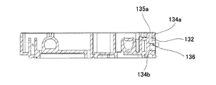
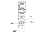
本体ケース102の一側面には、キャリッジ1に設けられたホルダ側に係合されるレバー120が設けられている。本体ケース102の一側面であって、例えばレバー120の下方位置には、インク供給部110の上流側であって、インク送出流路の終端位置が開口する開口部130が形成されている。開口部130の周縁には溶着用リブ132が形成されている。この開口部130に臨むインク送出流路134を上流バッファ室134a及び下流バッファ室134b(図2では符号を省略、後述の図3、図6及び図7を参照)に仕切る隔壁リブ136が形成されている。
On one side surface of the
(インク検出装置)
次に、本体ケース102、インク送出流路134及び隔壁リブ136を用いて構成される本発明に係る液体検出装置に係るインク検出装置200の概要について、図2及び図3を参照して説明する。図3は、図2に示すインクカートリッジ100のうち、インク検出装置200を拡大して示している。
(Ink detection device)
Next, an outline of the
図2及び図3において、インク検出装置200は、インク送出流路134が形成された樹脂製の本体ケース102と、本体ケース102の開口部130よりインク送出流路134に臨んで配置される金属製のセンサベース210と、センサベース210がインク送出流路134に臨む面とは逆側の面に搭載されたセンサチップ220と、センサベース210を開口部130に保持し、かつ、開口部130を封止するフィルム202と、本体ケース102内にてインク送出流路134を上流側バッファ室134aと下流側バッファ室134bとに仕切る隔壁136とを含んでいる。フィルム202は、センサベース210の上面に接着されると共に、開口部130の周囲の溶着用リブ132に溶着される。
2 and 3, the
なお、図3には底部バイパス400と中間バイパス500とが示されているが、これらの詳細については後述する。
3 shows a
図2及び図3では、インク検出装置200はさらに、センサベース210、センサチップ220及びフィルム202の上側に配置される押さえカバー230と、押さえカバー230に収容され、フィルム202に形成された孔202aを介してセンサチップ220と電気的に接触する端子242を備えた中継端子240と、押さえカバー230に収容され、かつ、中継端子240の端子244と電気的に接続される回路基板250とを有することができる。なお、本発明に係る液体検出装置200としては、押さえカバー230、中継端子240及び回路基板250は不可欠な構成要素ではない。
In FIG. 2 and FIG. 3, the
インク検出装置200の詳細について、図4〜図17を参照して説明する。図4は本体ケース102の正面図である。図4のA1−A1断面図である図5に示すように、インク送出流路134は、図1に示すインク供給部110に至る前の終端側の位置にて、開口部130によって露出されている。
Details of the
図4のB1−B1断面図である図6と、インクカートリッジ100の右側面図である図7に示すように、開口部130により露出されたインク送出流路134は、隔壁136により、上流バッファ室134aと下流バッファ室134bとに仕切られている。なお、図6に示すように、上流バッファ室134aに臨んで供給口135aが配置され、図4に示すように、下流バッファ室134bに臨んで排出口135bが配置されている。
As shown in FIG. 6 which is a B1-B1 sectional view of FIG. 4 and FIG. 7 which is a right side view of the
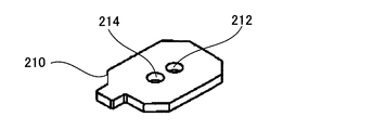
図8は、センサベース210を下方から見た斜視図である。図9に示すように、センサベース210には、厚さ方向で貫通する第1の孔(供給路)212と第2の孔(排出路)214とが設けられている。
FIG. 8 is a perspective view of the
図9は、センサチップ220が搭載されたセンサベース210を上方から見た斜視図である。また、図10は、図2及び図3に示すインク検出装置200のうち、開口部にセンサベース210とセンサチッブ220を配置した組み立てた状態を模式的に示す平面図である。また、図11は図10のC1−C1断面図、図12は図10のD1−D1断面図、図13は図10のE1−E1断面図、図14はセンサチップの断面図である。
FIG. 9 is a perspective view of the
図11、図12及び図14において、センサチップ220は検出対象のインク(液体)を受け入れるセンサキャビティ222を有しており、センサキャビティ222の裏面をインクの受け入れを可能とするために開放している。センサキャビティ222の表面は、図9及び図14に示すように振動板224で塞がれている。さらに、振動板224の表面に圧電素子226が配置されている。
11, 12, and 14, the
具体的に述べると、図14に示すように、センサチップ220は、キャビティ板300に振動板224を積層して構成されて、互いに対向する第1面300aおよび第2面300bを有した振動キャビティ形成基部300を有する。センサチップ220はさらに、キャビティ形成基部300の第2面300b側に積層された圧電素子226を備える。
More specifically, as shown in FIG. 14, the
振動キャビティ形成基部300には、検出対象の媒体(インク)を受け入れるための円筒形の空間形状を呈するキャビティ222が、第1面300a側に開口するようにして形成されており、キャビティ222の底面部222aが振動板224にて振動可能に形成されている。換言すれば、振動板224全体のうちの実際に振動する部分は、キャビティ222によってその輪郭が規定されている。振動キャビティ形成基部300の第2面300b側の両端には、電極端子228,228が形成されている。
In the vibration
振動キャビティ形成基部300の第2面300bには下部電極310が形成されており、この下部電極310は一方の電極端子228に接続されている。
A
下部電極310の上には圧電層312が積層されており、この圧電層312には、上部電極314が積層されている。上部電極314は、下部電極310と絶縁された補助電極320に接続されている。この補助電極320に他方の電極端子228が接続されている。
A
圧電素子226は、例えば、センサキャビティ222内のインクの有無による電気特性(例えば周波数)の違いでインクエンドを判断する機能を果たす。圧電層の材料としては、ジルコン酸チタン酸鉛(PZT)、ジルコン酸チタン酸鉛ランタン(PLZT)、または、鉛を使用しない鉛レス圧電膜、等を用いることができる。
The
センサチップ220は、チップ本体の下面をセンサベース210の上面中央部に載せることにより、接着層216によってセンサベース210に一体に固着されており、その接着層216によって同時に、センサベース210とセンサチップ220間がシールされている。
The
(インク残量検出)
図11に示すように、インク送出流路134の供給口135aから導入されたインクは、隔壁136で仕切られた一方の部屋である上流バッファ室134aに停留する。
(Remaining ink level detection)
As shown in FIG. 11, the ink introduced from the
この上流バッファ室134aは、センサベース210の第1の孔212を介して、センサチップ220のセンサキャビティ222と連通している。このため、上流バッファ室134a内のインクは、インク導出に伴って第1の孔212を介してセンサキャビティ222に導かれる。ここで、圧電素子226により振動される振動板224からの振動がインクに伝達され、その残留振動波形の周波数によって、インクの有無が検出される。センサキャビティ222に、インク以外に空気が混入するエンドポイトでは、残留振動波形の減衰が大きく、インクが充満状態のときと比べて高周波数となる。これを検出することで、インクエンド検出が可能となる。
The
具体的には、圧電素子226に電圧を印加すると、圧電素子226の変形に伴い振動板224が変形する。圧電素子226を強制的に変形させた後、電圧の印加を解除すると、しばらくは、たわみ振動が振動板224に残留する。この残留振動は、振動板224とセンサキャビティ222内の媒体との自由振動である。従って、圧電素子226に印加する電圧をパルス波形あるいは矩形波とすることで、電圧を印加した後の振動板224と媒体との共振状態を容易に得ることができる。
Specifically, when a voltage is applied to the
この残留振動は、振動板224の振動であり、圧電素子226の変形を伴う。このため、残留振動に伴って圧電素子226は逆起電力を発生する。
This residual vibration is vibration of the
回路基板250は、表裏面に貫通するスルーホール252に接続された電極を表裏面に有する。センサチップ220と接触する中継端子240からの信号は、スルーホール及び電極を介して、プリンタ本体に搭載される解析回路(図示せず)で処理され、その結果を回路基板250に搭載された半導体記憶装置(図示せず)に伝送される。つまり、圧電素子226の逆起電力は、中継端子240を介して解析回路に伝達され、その結果を半導体記憶装置に記憶される。
The
このようにして検出された逆起電力によって共振周波数が特定できるので、この共振周波数に基づいてインクカートリッジ100内のインクの有無を検出することができる。なお、半導体記憶装置には、インクカートリッジ100の種類等の識別情報と、インクカートリッジ100が保持するインクの色の情報ならびにインクの現存量等の情報が格納される。
Since the resonance frequency can be specified by the back electromotive force detected in this way, the presence or absence of ink in the
センサキャビティ222内に停留したインクは、さらなるインクの導出に伴って、図12に示すセンサベース210の第2の孔214を介して下流バッファ室134bに導かれる。さらには、インク排出口135bを介してインク送出流路134に沿って導出され、最終的にはインク供給部110(図2参照)を介してインクカートリッジ100より排出される。
The ink remaining in the
(センサベースの支持方法及び支持構造)
開口部130にセンサベース210、センサチップ220及びフィルム202を装着するには、次の二工程が必要である。つまり、センサチップ220が搭載された金属製センサベース210を、流路134が形成された本体ケース102の開口部130より流路134に臨んで配置する第1工程と、開口部130の周囲のリブ132にフィルム202を溶着して、フィルム202を介してセンサベース210を本体ケース102に支持する第2工程とが必要である。なお、第1工程及び第2の工程によって、センサチップ220に形成されたセンサキャビティ222が、センサベース210に形成された第1の孔212を介して上流バッファ室134aと連通され、かつ、センサベース210に形成された第2の孔214を介して下流バッファ室134bと連通されて、液体の検出経路を形成することは上述の通りである。
(Sensor base support method and support structure)
In order to attach the
本実施形態では、フィルム202の溶着前の第1工程にあっては、隔壁136によってのみセンサベース210が支持されている(隔壁による支持機能)。フィルム202が開口部130の周囲の溶着用リブ132に溶着される前にあっては、センサベース210が開口部130の所定の位置に仮位置決めされなければならないからである。また、第2工程にてフィルム202によってセンサベース210が支持された後は、開口部130の奥行き方向では、センサベース210は隔壁136のみと接触可能である(隔壁による上流・下流の仕切り機能)。なお、センサベース210はフィルム202によって支持されるので、センサベース210が常時隔壁136と接触していることは要求されないが、隔壁136の上流・下流仕切り機能は常時求められる。
In the present embodiment, in the first step before the
(センサベースの位置決め)
図10に示すように、センサベース210は、直交二軸でそれぞれ2辺が対向する計四辺を有する。センサベース210は、位置決めの必要から四辺を有するが、この各辺を結ぶ形状は問わない。本体ケース102の開口部130には、センサベース210の四辺と対向する位置に、センサベース210の四辺に向けて突出する四つの位置決め部150,151,152,153が設けられている。このうち、位置決め部150は、センサベース210の一辺、特に長辺に沿って長手状に形成され、底部バイパス400により2つに分離されている。他の位置決め部151〜153は、センサベース210の残りの三辺に対して局所的に設けられている。
(Sensor base positioning)
As shown in FIG. 10, the
センサベース210が有する、直交二軸でそれぞれ2辺が対向する計四辺と、それらと向かい合う4つの位置決め部150〜153との間の隙間F1に設計上で公差を設定することで、センサベース210が開口部130内に位置決めされることになる。また、4つの位置決め部のうちの少なくとも一つの位置決め部150が、センサベース210の一辺、特に長辺に沿って長手状に形成されることで、センサベース210の回転方向の位置決めに効果的である。ただし、隙間F1の領域を多く設定することは、気泡の発生から好ましくなく、回転規制の関係からは、長手状に形成される位置決め部は一辺に沿ってのみ形成すれば良い。
The
そして、四つの位置決め部150,151,152,153を除いた領域にて、開口部130を形成する壁部とセンサベース210の四辺との間には、上述した設計公差による隙間F1よりも充分に大きい隙間F2が形成されている。この隙間F2は、隔壁136にて仕切られた上流バッファ室134aまたは下流バッファ室134bにて形成される流路134の一部を形成している。
In the area excluding the four
本体ケース102内を真空に近い状態として、インクが充填される。このとき、上流バッファ室134aまたは下流バッファ室134bに連通している隙間F2も、インクの流路となり得るので、上流バッファ室134aおよび下流バッファ室134bにインクが充満されると、隙間F2にもインクが充満され、気泡が残留しない。これにより、インクエンドの誤検出を防止できる。
The
(インク検出時のインク流路と底部バイパス)
図15は、インク検出が実施されるインクカートリッジ使用時にて、上流側バッファ室134aから下流側バッファ室134bに向かうインクの流路を模式的に示している。インクカートリッジ使用時には、図15に示すように、センサベース210の第1,第2の孔212,214は、鉛直方向にて同一高さ位置に並んで配置される。そして、第1,第2の孔212,214の間に位置して鉛直方向にてセンサベース210に沿って延びる隔壁136の両側の一方が上流側バッファ室134aとり、他方が下流側バッファ室134bとなる。インク検出時には、図15に示すように、上流側バッファ室134a内のインクは、センサベース210の第1の孔212を通過してセンサキャビティ222に移動し、センサベース210の第2の孔214を介して下流側バッファ室134bに移動する。これが第1の流路FR1である。もし、上流側及び下流側バッファ室134a,134b内の液位が下がり、第1の孔212を介して空気がセンサキャビティ222内に移動すると、上述した通りインク無しが検出される。
(Ink flow path and bottom bypass when detecting ink)
FIG. 15 schematically shows an ink flow path from the
ここで、図15に示すように、上流側バッファ室134a内のインクは、上流側バッファ室134aの鉛直方向の最上部でなく中間部にて開口するセンサベース210の第1の孔212を介してセンサキャビティ222に向かう。よって、もし上流側バッファ室134aに気泡が混入していても、比重の軽い気泡は鉛直上方に向うので、その気泡がセンサキャビティ222に移動しにくい。よって、特許文献2,3の構造よりも、インク中の気泡による誤検出は生じにくい。
Here, as shown in FIG. 15, the ink in the
次に、本実施形態では、図15に示すように、上流側及び下流側バッファ室134a,134b内での鉛直方向の最下方位置にて開口401,402を有し、隔壁136の下方を経由して、上流側及び下流側バッファ室134a,134b同士を連通させる底部バイパス400を有する。この底部バイパス400によるインク流路を第2の流路FR2とする。この底部バイパス400は、図3及び図10〜図12にも示されている。図10〜図12及び図15に示すように、底部バイパス400は、インクカートリッジ使用時にてセンサベース210の最下端部210aよりも下方に形成されている。換言すれば、図15に示すように、底部バイパス400は、インクカートリッジ使用時にて隔壁136の最下端部136aよりも下方に形成されている。このため、このセンサベース210を支持する隔壁136を切り欠かなくても、底部バイパス400を形成することができる。
Next, in this embodiment, as shown in FIG. 15,
なお、底部バイパス400は、図11に示すように、センサベース210の最下端部210aよりも下方の本体ケース102を切り欠くと共に、その開口部側がフィルム202により封止されることで形成されている。ただし、必ずしもフィルム202で封止するものに限らず、本体ケース202に形成される溝だけで形成しても良い。
As shown in FIG. 11, the
ここで、センサベース210を支持する隔壁136を切り欠かなくても、底部バイパス400を形成することは、センサベース210の傾きを防止できる点で好ましい。ここで、センサベース210は、図3に示すようにセンサベース210に搭載されるセンサチッブ220が、中継端子240の端子242と接触することで押圧される。このため、底部バイパス400を形成するために隔壁136に切り欠きを設けると、センサベース210を支持する隔壁136の接触面積が少なくなり、端子242からの押圧力で傾きやすくなる。結果として、端子242とセンサチッブ220との接触不良が生じやすくなるが、本実施形態ではそのような弊害はない。
Here, even if the
また、底部バイパス400を流れるインクの流路(第2の流路RF2)の流路抵抗R2は、第1の孔212からセンサキャビティ222を経て第2の孔214に流れるインクの流路(第1の流路FR1)の流路抵抗R1と同等以上である(R2≧R1)。つまり、第2の流路RF2では、第1の流路RF1と同等に流れやすいか、あるいは第1の流路RF1よりも流れにくくなっている。これにより、インク検出時には第1の流路RF1を主体的に使用することを担保しながら、上流側及び下流側バッファ室134a,134b間でのトータルの流路抵抗を下げてインクを流れやすくすることが可能となる。
Further, the flow path resistance R2 of the ink flow path (second flow path RF2) flowing through the
図15において、同一高さにある第1,第2の孔212,214よりも液位が低くなった時には、もはや第1の流路RF1にインクは流れない。しかし、上流側バッファ室134aに残存したインクは、底部バイパス400を用いた第2の流路RF2を介して下流側バッファ室134bに移動させることができる。よって、上流側バッファ室134a内のインクを最後まで有効利用することができる。
In FIG. 15, when the liquid level becomes lower than the first and
(底部バイパスの変形例)
図16は、底部バイパスの変形例を示している。図16において、隔壁136の下方には本体ケース102を切り欠いたバイパス410が設けられている。一方、センサベース210は隔壁136よりも下方に長い延長部216を有し、その延長部216の一部に切り欠き部216aが設けられている。この切り欠き部216aは、隔壁136の厚さよりも広いスペースで切り欠かれている。この切り欠き部216aを含むセンサベース210の表面側はフィルム202で封止され、切り欠き部216aの裏面側はバイパス410と対面している。底部バイパス420は、バイパス410、それに連通する切り欠き部216a及び切り欠き部216aの表面側を封止するフィルム202とで形成されている。
(Modification of bottom bypass)
FIG. 16 shows a modification of the bottom bypass. In FIG. 16, a
この構造では、センサベース210に切り欠き部216aを設けているが、切り欠き部216aは、隔壁136と接触しない延長部216に設けられている。よって、この場合も、センサベース210を支持する隔壁136の接触面積は確保でき、端子242からの押圧力でセンサベース210が傾くことはない。
In this structure, the
なお、センサベース210の切り欠き部216aだけで底部バイパスを構成しても良く、この場合は、図17に示すように、上流側及び下流側バッファ室134a,134bの最下端部にて開口し、かつ、隔壁136と対向する位置にて、隔壁136の厚さよりも広いスペースに亘って切り欠かれた切り欠き部218を、センサベース210の最下段部に形成すれば良い。
Note that the bottom portion bypass may be configured only by the
(中間バイパス)
本実施形態では、図3、図11及び図12に示すように、隔壁136がセンサベース210と対面する位置にて、隔壁の一部が上流側及び下流側バッファ室134a,134bと連通するように切り欠かれて形成された一つの中間バイパス500をさらに有する。
(Intermediate bypass)
In this embodiment, as shown in FIGS. 3, 11, and 12, a part of the partition wall is in communication with the upstream and
図3、図11及び図12の例では、中間バイパス500は、インクカートリッジ使用時の鉛直方向での第1及び第2の孔212,214と底部バイパス400との間の位置にて、隔壁136を切り欠くことで形成されている。
In the example of FIGS. 3, 11, and 12, the
この中間バイパス500の作用について図18を参照して説明する。図18は、上流側バッファ室134a内のインクが無くなった状態を想定した図である。従って、図18の状態になる以前に、センサキャビティ222には空気が取り込まれるので、「インク無し」が検出されている。
The operation of the
図18では、センサベース210の一面212bと隔壁136の対向面136bとの間に僅かな隙間があり、その隙間に毛細管現象にてインク600が下方より上方に向けて上昇した状態を示している。
FIG. 18 shows a state in which there is a slight gap between one surface 212b of the
本実施形態では、底部バイパス400が存在するので、インク無し検出後でも上流側バッファ室134a内のインクはほぼ全て下流側バッファ室134bに排出できる。ただし、その排出過程や、下流側バッファ室134bにインクが残留している時点で、センサベース210の一面212bと隔壁136の対向面136bとの間に僅かな隙間にて、強い毛細管現象が作用する。このため、残留インクはその隙間に沿って上昇する。
In the present embodiment, since the
本実施形態では、その上昇経路の途中に中間バイパス500が存在する。この中間バイパス500の位置で強い毛細管現象は弱められ、上昇したインクを中間バイパス500にてトラップできる。従って、インクがさらに上昇を続けて、第1の孔212を介してセンサキャビティ222に入り込み、「インク有り」を誤検出することは防止できる。
In the present embodiment, an
インク検出は、図1に示すキャリッジ1が印字領域以外のポジション例えばホームポジションに来た位置で実施している。例えば、最後の印字で「インク無し」を検出し、その数日後にプリンタを駆動した時に、毛細管現象によってセンサキャビティ222がインクで満たされ、「インク有り」と誤検出してしまうことがある。あるいは、印字途中で上流バッファ室134bが空となったのに、キャリッジ1がホームポジションに到達した段階で、毛細管現象による素早いインクの移動によってセンサキャビティ222がインクで満たされ、「インク有り」と誤検出してしまうことがある。
Ink detection is performed at a position where the carriage 1 shown in FIG. 1 comes to a position other than the print area, for example, a home position. For example, when “no ink” is detected in the last printing and the printer is driven several days later, the
本実施形態では、毛細管現象によるインクの上昇経路途中に中間バイパス500を設けることにより、上述の弊害を防止することができる。
In the present embodiment, the above-described adverse effects can be prevented by providing the
ここで、中間バイパス500は毛細管現象により移動するインクをトラップすることが本来的機能であるが、上流側及び下流側バッファ室134a,134b間を連通させてインク流路を形成するバイパスの役目も有する。このバイパスの役目は、毛細管現象が始まる前には中間バイパス500にインクが停留していないことを担保するために必要である。毛細管現象が始まる前から中間バイパス500にインクがトラップされていると、毛細管現象後のインクトラップ機能を果たせないからである。
Here, the
ただし、中間バイパス500を流れるインクの流路抵抗R3は、底部バイパス400を流れるインクの流路抵抗R2よりも充分に大きい(R3≫R2)。つまり、上流側バッファ室134aから下流側バッファ室134bに向うインクは、図15に示す第1の流路FR1で最も流れやすく、次に流れやすいのが第2の流路FR2であり、中間バイパス500で最も流れにくい。よって、上流側バッファ室134aから下流側バッファ室134bに向うインクのトータルの流路抵抗は低下して流れやすくなるが、センサキャビティ222にて確実にインク検出することが担保される。
However, the flow path resistance R3 of the ink flowing through the
(中間バイパスの変形例)
図19は中間バイパスの変形例を示している。図19は、底部バイパス400を有していないインク検出装置に中間バイパスを設けている。図19では、インクカートリッジ使用時に、第1,第2の孔212,214の高さ位置よりも下方に複数例えば2つの中間バイパス510,512を設けている。図19ではさらに、第1,第2の孔212,2214の高さ位置よりも上方に複数例えば2つの中間バイパス514,516を設けている。
(Modified example of intermediate bypass)
FIG. 19 shows a modification of the intermediate bypass. In FIG. 19, an intermediate bypass is provided in an ink detection device that does not have a
図19の例では、底部バイパス400が存在しないので、上流側バッファ314aにもインク600が残留しやすい。このため、上流側バッファ314aに残留したインク600が、センサベース210の一面212bと隔壁136の対向面136bとの間に僅かな隙間に沿って、毛細管現象により上昇する。しかし、その上昇経路に設けた複数の中間バイパス510,512により、インク600がトラップされて、センサキャビティ222まで到達することを防止できる。
In the example of FIG. 19, since the
この毛細管現象は第1,第2の孔212,214の上方でも生ずることはある。なぜなら、センサベース210と隔壁136とが交わるエッジには強いメニスカスが形成され、そこに残留したインク600が毛細管現象によってセンサベース210の一面212bと隔壁136の対向面136bとの間に僅かな隙間に沿って移動するからである。この場合、隙間に沿ってインク600が下降するが、その下降経路に設けた複数の中間バイパス514,516により、インク600がトラップされて、センサキャビティ222まで到達することを防止できる。
This capillary action may also occur above the first and
なお、図19に示すインク600の上昇及び下降経路の各々に中間バイパスを一つ設けるものでも良い。また、図18に示すように、底部バイパス400を有するインク検出装置であっても、インク600の上昇経路に中間バスパスを複数も受けることができ、あいるは、インク下降経路に中間バイパスを少なくとも一つ設けても良い。
Note that one intermediate bypass may be provided for each of the upward and downward paths of the
なお、上記のように本実施形態について詳細に説明したが、本発明の新規事項および効果から実体的に逸脱しない多くの変形が可能であることは当業者には容易に理解できるものである。従って、このような変形例はすべて本発明の範囲に含まれるものとする。例えば、明細書又は図面において、少なくとも一度、より広義または同義な異なる用語と共に記載された用語は、明細書又は図面のいかなる箇所においても、その異なる用語に置き換えることができる。 Although the present embodiment has been described in detail as described above, those skilled in the art can easily understand that many modifications can be made without departing from the novel matters and effects of the present invention. Accordingly, all such modifications are intended to be included in the scope of the present invention. For example, a term described at least once together with a different term having a broader meaning or the same meaning in the specification or the drawings can be replaced with the different term in any part of the specification or the drawings.
例えば、上述した実施形態では、インクカートリッジ使用時にセンサベース210が垂直に立てられた使用状態を示した。しかし、これに限らず、センサベース210を鉛直方向に対して傾けて使用しても良い。図20及び図21は、鉛直線Lに対して、インクカートリッジ200を所定角度だけ左または右に回転させて、センサベース210の傾斜状態を示している。何れの場合も、底部バイパス400は上流側バッファ室134aの最下方位置にて開口しており、しかもその高さ位置はセンサキャビティ222への入り口位置よりも低い。このため、上流側バッファ室134aに残留したインクを、底部バイパス400を経由させて下流側バッファ室134bに移動させることができる。
For example, in the above-described embodiment, the use state in which the
本発明の液体収容容器の用途は、インクジェット記録装置のインクカートリッジに限らない。微小量の液滴を吐出させる液体噴射ヘッド等を備える各種の液体消費装置に流用可能である。 The use of the liquid container of the present invention is not limited to the ink cartridge of the ink jet recording apparatus. The present invention can be used for various liquid consuming devices including a liquid ejecting head that discharges a minute amount of liquid droplets.
液体消費装置の具体例としては、例えば液晶ディスプレイ等のカラーフィルタ製造に用いられる色材噴射ヘッドを備えた装置、有機ELディスプレイ、面発光ディスプレイ(FED)等の電極形成に用いられる電極材(導電ペースト)噴射ヘッドを備えた装置、バイオチップ製造に用いられる生体有機物噴射ヘッドを備えた装置、精密ピペットとしての試料噴射ヘッドを備えた装置、捺染装置やマイクロデスペンサ等が挙げられる。 Specific examples of the liquid consuming device include, for example, an electrode material (conducting material) used for forming an electrode such as a device having a color material ejecting head used for manufacturing a color filter such as a liquid crystal display, an organic EL display, and a surface emitting display (FED) Examples thereof include an apparatus having a paste) ejection head, an apparatus having a bio-organic matter ejection head used for biochip manufacturing, an apparatus having a sample ejection head as a precision pipette, a textile printing apparatus, and a micro dispenser.
また、本発明の液体検出装置は、オンキャリッジタイプのインクカートリッジに組み込まれるものに限らず、キャリジに搭載されないサブタンクや、オフキャリジタイプのインクカートリッジ等に組み込まれても良い。 The liquid detection device of the present invention is not limited to being incorporated in an on-carriage type ink cartridge, but may be incorporated in a sub-tank not mounted on a carriage, an off-carriage type ink cartridge, or the like.
さらには、上述した実施形態では、液体検出装置のケースを液体収容容器の本体ケースの一部として、特許文献2のようなシーリングゴムやスプリングを排除したが、これに限定されない。液体収容容器のケース本体とは別個のユニットとして液体検出装置を構成しても良い。この場合のケースとはユニットケースを意味する。この場合、シーリングゴムやスプリングを排除できないかもしれないが、ユニットケースが大型化したとしても、そのユニットケースでの振動吸収を最小限に抑えて検出波形の振幅を大きく確保することに寄与できる。 Furthermore, in the above-described embodiment, the case of the liquid detection device is used as a part of the main body case of the liquid container, and the sealing rubber and the spring as in Patent Document 2 are excluded, but the present invention is not limited to this. The liquid detection device may be configured as a unit separate from the case main body of the liquid container. The case in this case means a unit case. In this case, the sealing rubber and the spring may not be excluded, but even if the unit case is enlarged, it is possible to contribute to ensuring a large amplitude of the detected waveform by minimizing vibration absorption in the unit case.
上記実施形態において、液体噴射装置を、記録用紙(図示略)の搬送方向(前後方向)と交差する方向において記録ヘッド19が記録用紙(図示略)の幅方向(左右方向)の長さに対応した全体形状をなす、いわゆるフルラインタイプ(ラインヘッド方式)のプリンタに具体化してもよい。 In the above embodiment, the liquid ejecting apparatus corresponds to the length of the recording paper (not shown) in the width direction (left and right direction) in the direction intersecting the conveyance direction (front and back direction) of the recording paper (not shown). The present invention may be embodied in a so-called full line type (line head type) printer.
上記実施形態では、液体噴射装置をインクジェット式プリンタ11に具体化したが、この限りではなく、インク以外の他の液体(機能材料の粒子が液体に分散又は混合されてなる液状体、ゲルのような流状体を含む)を噴射したり吐出したりする液体噴射装置に具体化することもできる。例えば、液晶ディスプレイ、EL(エレクトロルミネッセンス)ディスプレイ及び面発光ディスプレイの製造などに用いられる電極材や色材(画素材料)などの材料を分散または溶解のかたちで含む液状体を噴射する液状体噴射装置、バイオチップ製造に用いられる生体有機物を噴射する液体噴射装置、精密ピペットとして用いられ試料となる液体を噴射する液体噴射装置であってもよい。さらに、時計やカメラ等の精密機械にピンポイントで潤滑油を噴射する液体噴射装置、光通信素子等に用いられる微小半球レンズ(光学レンズ)などを形成するために紫外線硬化樹脂等の透明樹脂液を基板上に噴射する液体噴射装置、基板などをエッチングするために酸又はアルカリ等のエッチング液を噴射する液体噴射装置、ゲル(例えば物理ゲル)などの流状体を噴射する流状体噴射装置であってもよい。そして、これらのうちいずれか一種の液体噴射装置に本発明を適用することができる。なお、本明細書において「液体」とは、気体のみからなる液体を含まない概念であり、液体には、例えば無機溶剤、有機溶剤、溶液、液状樹脂、液状金属(金属融液)等のほかに、液状体、流状体などが含まれる。
In the above embodiment, the liquid ejecting apparatus is embodied in the
100 液体収容容器(インクカートリッジ)、102 ケース、
102a 流路壁、110 液体供給部、130 開口部、132 溶着用リブ、
134 流路(送出流路)、134a 上流バッファ室、134a1 間仕切壁、
134b 下流バッファ室、134b1 間仕切壁、135a 供給口、
135b 排出口、136 隔壁、136a 最下端部、136b 対向端部、
138、補助支持部、150〜153 位置決め部、200 液体検出装置、
202 フィルム、210 センサベース、212 第1の孔(供給路)、
214 第2の孔(排出路)、216 延長部、216a,218 切り欠き部、
220 センサチップ、222 センサキャビティ、224 振動板、
226 圧電素子、228 電極、230 押さえカバー、240 中継端子、
250 回路基板、300 キャビティ形成基部、300a 第1面、
300b 第2面、 400,420 底部バイパス、500〜516 中間バイパス、
600 インク、F1 公差上の隙間、F2 隙間
100 liquid container (ink cartridge), 102 case,
102a channel wall, 110 liquid supply part, 130 opening part, 132 welding rib,
134 channel (delivery channel), 134a upstream buffer chamber, 134a1 partition wall,
134b Downstream buffer chamber, 134b1 partition wall, 135a supply port,
135b outlet, 136 partition, 136a bottom end, 136b opposite end,
138, auxiliary support part, 150 to 153 positioning part, 200 liquid detection device,
202 film, 210 sensor base, 212 first hole (supply path),
214 second hole (discharge channel), 216 extension, 216a, 218 notch,
220 sensor chip, 222 sensor cavity, 224 diaphragm,
226 piezoelectric element, 228 electrode, 230 holding cover, 240 relay terminal,
250 circuit board, 300 cavity forming base, 300a first surface,
300b second side, 400, 420 bottom bypass, 500-516 intermediate bypass,
600 ink, F1 clearance, F2 clearance
Claims (13)
前記開口部より前記流路に臨んで配置されるセンサベースと、
前記センサベースが前記流路に臨む面とは逆側の面に搭載されたセンサチップと、
前記センサベースを前記開口部に保持し、かつ、前記開口部を封止するフィルムと、
前記ケース内にて前記流路の一部を上流側バッファ室と下流側バッファ室とに仕切る隔壁と、
を備え、
前記センサチップは、検出対象の液体を受け入れるセンサキャビティを有し、
前記センサベースは、前記上流側バッファ室より前記センサキャビティに前記液体を導く第1の孔と、前記センサキャビティより前記下流側バッファ室に前記液体を導く第2の孔と、を含み、
液体検出する使用時に、前記第1,第2の孔が鉛直方向にて同一高さ位置に並んで配置されるように前記センサベースを垂直に配置し、前記第1,第2の孔の間に位置して鉛直方向にて前記センサベースに沿って延びるように前記隔壁を配置し、かつ、前記センサベースの下端部よりも下方位置にて開口して、前記上流側及び下流側バッファ室同士を連通させる底部バイパスを設けたことを特徴とする液体検出装置。 A case in which the flow path is exposed through the opening;
A sensor base disposed facing the flow path from the opening;
A sensor chip mounted on a surface opposite to the surface where the sensor base faces the flow path;
A film for holding the sensor base in the opening and sealing the opening;
A partition that partitions a part of the flow path into an upstream buffer chamber and a downstream buffer chamber in the case;
With
The sensor chip has a sensor cavity for receiving a liquid to be detected;
The sensor base includes a first hole that guides the liquid from the upstream buffer chamber to the sensor cavity, and a second hole that guides the liquid from the sensor cavity to the downstream buffer chamber;
In use of detecting liquid, the first, the sensor base is disposed vertically so that are arranged side by side at the same height position at the second hole vertically, between the first and second holes The partition wall is disposed so as to extend along the sensor base in the vertical direction, and is opened at a position lower than the lower end portion of the sensor base, so that the upstream and downstream buffer chambers are A liquid detection device comprising a bottom bypass for communicating with each other.
前記底部バイパスを流れる液体の流路抵抗は、前記第1の孔から前記センサキャビティを経て前記第2の孔に流れる液体の流路抵抗と同等以上であることを特徴とする液体検出装置。 In claim 1,
The liquid flow resistance of the liquid flowing through the bottom bypass is equal to or higher than the flow resistance of the liquid flowing from the first hole to the second hole through the sensor cavity.
前記底部バイパスは、前記使用時にて前記隔壁が鉛直方向の最下端部となる位置の下方に形成されていることを特徴とする液体検出装置。 In claim 1 or 2,
The liquid detection device according to claim 1, wherein the bottom bypass is formed below a position where the partition wall is the lowest end in the vertical direction during the use.
前記底部バイパスは、前記使用時にて前記センサベースが鉛直方向の最下端部となる位置よりも下方に形成されていることを特徴とする液体検出装置。 In any one of Claims 1 thru | or 3,
The liquid detection device according to claim 1, wherein the bottom bypass is formed below a position where the sensor base is the lowest end in the vertical direction during the use.
前記底部バイパスの流路の一面は、前記フィルムによって形成されていることを特徴とする液体検出装置。 In claim 4,
One surface of the bottom bypass flow path is formed by the film.
前記センサベースは切り欠き部を含み、
前記底部バイパスは、前記センサベースの前記切り欠き部と前記フィルムとによって区画形成されていることを特徴とする液体検出装置。 In claim 1 or 2,
The sensor base includes a notch,
The liquid detection apparatus according to claim 1, wherein the bottom bypass is defined by the cutout portion of the sensor base and the film.
前記隔壁が前記センサベースと対面する位置にて、前記隔壁の一部が前記上流側及び下流側バッファ室と連通するように切り欠かれて形成された少なくとも一つの中間バイパスをさらに有することを特徴とする液体検出装置。 In any one of Claims 1 thru | or 6.
The partition further includes at least one intermediate bypass formed by notching so that a part of the partition communicates with the upstream and downstream buffer chambers at a position where the partition faces the sensor base. A liquid detection device.
前記少なくとも一つの中間バイパスは、前記使用時の鉛直方向での前記第1及び第2の孔と前記底部バイパスとの間の位置にて、前記隔壁を切り欠くことで形成されていることを特徴とする液体検出装置。 In claim 7,
The at least one intermediate bypass is formed by cutting out the partition wall at a position between the first and second holes and the bottom bypass in the vertical direction during use. A liquid detection device.
前記少なくとも一つの中間バイパスを流れる液体の流路抵抗は、前記底部バイパスを流れる液体の流路抵抗よりも大きいことを特徴とする液体検出装置。 In claim 7 or 8,
The liquid detection apparatus according to claim 1, wherein a flow path resistance of the liquid flowing through the at least one intermediate bypass is larger than a flow path resistance of the liquid flowing through the bottom bypass.
前記センサチップは圧電素子を含み、
前記センサベースは、前記開口部の奥行き方向では、前記センサベースの前記第1,第2の孔の間に位置して、前記隔壁のみを介して前記ケースと接触可能であることを特徴とする液体検出装置。 In any one of Claims 1 thru | or 9,
The sensor chip includes a piezoelectric element;
The sensor base is positioned between the first and second holes of the sensor base in the depth direction of the opening, and can contact the case only through the partition wall. Liquid detection device.
前記センサベースは、直交する二軸方向にてそれぞれ二辺が対向する四辺を有する形状を有し、
前記ケースの少なくとも前記開口部には、前記センサベースの四辺と対向する位置に、前記センサベースの前記四辺に向けて突出する少なくとも四つの位置決め部が設けられ、
前記少なくとも四つの位置決め部を除いた領域にて、前記開口部を形成する壁部と前記センサベースの四辺との間の隙間が、前記上流側バッファ室または前記下流側バッファ室での前記流路の一部を形成することを特徴とする液体検出装置。 In any one of Claims 1 thru | or 10.
The sensor base has a shape having four sides opposite to each other in two orthogonal axial directions,
At least the four positioning portions that protrude toward the four sides of the sensor base are provided at positions that face the four sides of the sensor base at least in the opening of the case.
In the region excluding the at least four positioning portions, the gap between the wall portion forming the opening and the four sides of the sensor base is the flow path in the upstream buffer chamber or the downstream buffer chamber. Forming a part of the liquid detection device.
前記ケースは、前記液体を収容する容器の一部であることを特徴とする液体検出装置。 In any one of Claims 1 thru | or 11,
The liquid detection apparatus according to claim 1, wherein the case is a part of a container that stores the liquid.
前記開口部より前記送出流路に臨んで配置されるセンサベースと、
前記センサベースが前記送出流路に臨む面とは逆側の面に搭載されたセンサチップと、
前記センサベースを前記開口部に保持し、かつ、前記開口部を封止するフィルムと、
前記ケース内にて前記送出流路の一部を上流側バッファ室と下流側バッファ室とに仕切る隔壁と、を備え、
前記センサチップは、検出対象の液体を受け入れるセンサキャビティを有し、
前記センサベースは、前記上流側バッファ室より前記センサキャビティに前記液体を導く第1の孔と、前記センサキャビティより前記下流側バッファ室に前記液体を導く第2の孔と、を含み、
液体検出する使用時に、前記第1,第2の孔が鉛直方向にて同一高さ位置に並んで配置されるように前記センサベースを垂直に配置し、前記第1,第2の孔の間に位置して鉛直方向にて前記センサベースに沿って延びるように前記隔壁を配置し、かつ、前記センサベースの下端部よりも下方位置にて開口して、前記上流側及び下流側バッファ室同士を連通させる底部バイパスを設けたことを特徴とする液体収容容器。
A case in which a liquid container, a delivery channel communicating with the liquid container, and an opening exposing the delivery channel are formed;
A sensor base disposed facing the delivery channel from the opening;
A sensor chip mounted on a surface opposite to the surface where the sensor base faces the delivery flow path;
A film for holding the sensor base in the opening and sealing the opening;
A partition that partitions a part of the delivery channel into an upstream buffer chamber and a downstream buffer chamber in the case, and
The sensor chip has a sensor cavity for receiving a liquid to be detected;
The sensor base includes a first hole that guides the liquid from the upstream buffer chamber to the sensor cavity, and a second hole that guides the liquid from the sensor cavity to the downstream buffer chamber;
In use of detecting liquid, the first, the sensor base is disposed vertically so that are arranged side by side at the same height position at the second hole vertically, between the first and second holes The partition wall is disposed so as to extend along the sensor base in the vertical direction, and is opened at a position lower than the lower end portion of the sensor base, so that the upstream and downstream buffer chambers are A liquid container having a bottom bypass for communicating with each other.
Priority Applications (2)
| Application Number | Priority Date | Filing Date | Title |
|---|---|---|---|
| JP2007311195A JP5286759B2 (en) | 2007-11-30 | 2007-11-30 | Liquid detection device and liquid container using the same |
| US12/325,796 US7802861B2 (en) | 2007-11-30 | 2008-12-01 | Liquid detector and liquid container having the same |
Applications Claiming Priority (1)
| Application Number | Priority Date | Filing Date | Title |
|---|---|---|---|
| JP2007311195A JP5286759B2 (en) | 2007-11-30 | 2007-11-30 | Liquid detection device and liquid container using the same |
Publications (3)
| Publication Number | Publication Date |
|---|---|
| JP2009132085A JP2009132085A (en) | 2009-06-18 |
| JP2009132085A5 JP2009132085A5 (en) | 2011-01-13 |
| JP5286759B2 true JP5286759B2 (en) | 2013-09-11 |
Family
ID=40844233
Family Applications (1)
| Application Number | Title | Priority Date | Filing Date |
|---|---|---|---|
| JP2007311195A Expired - Fee Related JP5286759B2 (en) | 2007-11-30 | 2007-11-30 | Liquid detection device and liquid container using the same |
Country Status (2)
| Country | Link |
|---|---|
| US (1) | US7802861B2 (en) |
| JP (1) | JP5286759B2 (en) |
Families Citing this family (5)
| Publication number | Priority date | Publication date | Assignee | Title |
|---|---|---|---|---|
| EP1974925B1 (en) * | 2007-03-30 | 2011-06-15 | Seiko Epson Corporation | Liquid detection device, liquid container using the same, and method of producing liquid detection device |
| JP5506452B2 (en) * | 2010-02-25 | 2014-05-28 | エスアイアイ・プリンテック株式会社 | Pressure buffer, liquid ejecting head, and liquid ejecting apparatus |
| JP2011173398A (en) * | 2010-02-25 | 2011-09-08 | Sii Printek Inc | Pressure damper, liquid jet head, liquid jet apparatus, and pressure damping method |
| JP5454398B2 (en) * | 2010-07-15 | 2014-03-26 | セイコーエプソン株式会社 | Liquid container, tank unit, and liquid ejection system |
| JP6586754B2 (en) * | 2015-03-20 | 2019-10-09 | セイコーエプソン株式会社 | Liquid consumption device |
Family Cites Families (8)
| Publication number | Priority date | Publication date | Assignee | Title |
|---|---|---|---|---|
| US6799820B1 (en) * | 1999-05-20 | 2004-10-05 | Seiko Epson Corporation | Liquid container having a liquid detecting device |
| JP3818018B2 (en) * | 1999-05-20 | 2006-09-06 | セイコーエプソン株式会社 | Liquid container |
| JP2007015408A (en) | 2003-01-21 | 2007-01-25 | Seiko Epson Corp | Liquid cartridge |
| JP2005343036A (en) * | 2004-06-03 | 2005-12-15 | Canon Inc | Ink residual quantity detection module for inkjet recording, ink tank with the ink residual quantity detection module, and inkjet recorder |
| JP4784087B2 (en) * | 2004-12-13 | 2011-09-28 | セイコーエプソン株式会社 | Mounting structure of liquid detection device and liquid container |
| EP1863644A1 (en) * | 2005-03-31 | 2007-12-12 | Seiko Epson Corporation | Container having liquid detecting function, and sensor unit |
| JP4613667B2 (en) * | 2005-03-31 | 2011-01-19 | セイコーエプソン株式会社 | Liquid detection device, liquid container, and manufacturing method of liquid detection device |
| JP4821429B2 (en) * | 2005-05-12 | 2011-11-24 | セイコーエプソン株式会社 | Container with liquid detection function |
-
2007
- 2007-11-30 JP JP2007311195A patent/JP5286759B2/en not_active Expired - Fee Related
-
2008
- 2008-12-01 US US12/325,796 patent/US7802861B2/en active Active
Also Published As
| Publication number | Publication date |
|---|---|
| US7802861B2 (en) | 2010-09-28 |
| JP2009132085A (en) | 2009-06-18 |
| US20090174734A1 (en) | 2009-07-09 |
Similar Documents
| Publication | Publication Date | Title |
|---|---|---|
| JP5088193B2 (en) | Liquid container | |
| JP5272540B2 (en) | Liquid container manufacturing method and liquid container | |
| KR101096845B1 (en) | Liquid delivery system and manufacturing method thereof | |
| JP5088694B2 (en) | Liquid container and manufacturing method thereof | |
| JP4985500B2 (en) | Liquid supply system and manufacturing method therefor | |
| KR20090101108A (en) | Liquid delivery system and manufacturing method for the same | |
| JP5286759B2 (en) | Liquid detection device and liquid container using the same | |
| JP5082723B2 (en) | Liquid detection device, liquid container using the same, and method for manufacturing liquid detection device | |
| US20090102897A1 (en) | Liquid Contanier | |
| JP4985302B2 (en) | Liquid detection device and liquid container using the same | |
| JP4984429B2 (en) | Container with liquid detection function | |
| EP1974925B1 (en) | Liquid detection device, liquid container using the same, and method of producing liquid detection device | |
| JP5487744B2 (en) | Method for manufacturing liquid container | |
| JP4894233B2 (en) | Container with liquid detection function | |
| JP4301306B2 (en) | Liquid ejecting head and liquid ejecting apparatus | |
| JP5326618B2 (en) | Liquid detection device and liquid container using the same | |
| US20090102903A1 (en) | Liquid Jetting Apparatus | |
| US8857957B2 (en) | Liquid container and method of manufacturing liquid container | |
| RU2414355C2 (en) | Container for liquid | |
| JP2010167691A (en) | Sensor unit and liquid container |
Legal Events
| Date | Code | Title | Description |
|---|---|---|---|
| A521 | Request for written amendment filed |
Free format text: JAPANESE INTERMEDIATE CODE: A523 Effective date: 20101118 |
|
| A621 | Written request for application examination |
Free format text: JAPANESE INTERMEDIATE CODE: A621 Effective date: 20101118 |
|
| A977 | Report on retrieval |
Free format text: JAPANESE INTERMEDIATE CODE: A971007 Effective date: 20120815 |
|
| A131 | Notification of reasons for refusal |
Free format text: JAPANESE INTERMEDIATE CODE: A131 Effective date: 20120828 |
|
| A521 | Request for written amendment filed |
Free format text: JAPANESE INTERMEDIATE CODE: A523 Effective date: 20121025 |
|
| TRDD | Decision of grant or rejection written | ||
| A01 | Written decision to grant a patent or to grant a registration (utility model) |
Free format text: JAPANESE INTERMEDIATE CODE: A01 Effective date: 20130507 |
|
| A61 | First payment of annual fees (during grant procedure) |
Free format text: JAPANESE INTERMEDIATE CODE: A61 Effective date: 20130520 |
|
| R150 | Certificate of patent or registration of utility model |
Ref document number: 5286759 Country of ref document: JP Free format text: JAPANESE INTERMEDIATE CODE: R150 |
|
| S531 | Written request for registration of change of domicile |
Free format text: JAPANESE INTERMEDIATE CODE: R313531 |
|
| R350 | Written notification of registration of transfer |
Free format text: JAPANESE INTERMEDIATE CODE: R350 |
|
| LAPS | Cancellation because of no payment of annual fees |