EP1471416A1 - STORAGE SYSTEM, STORAGE CONTROL PROGRAM, STORAGE CONTROL METHOD - Google Patents
STORAGE SYSTEM, STORAGE CONTROL PROGRAM, STORAGE CONTROL METHOD Download PDFInfo
- Publication number
- EP1471416A1 EP1471416A1 EP02716413A EP02716413A EP1471416A1 EP 1471416 A1 EP1471416 A1 EP 1471416A1 EP 02716413 A EP02716413 A EP 02716413A EP 02716413 A EP02716413 A EP 02716413A EP 1471416 A1 EP1471416 A1 EP 1471416A1
- Authority
- EP
- European Patent Office
- Prior art keywords
- data
- cache
- disk
- storage
- controlling device
- Prior art date
- Legal status (The legal status is an assumption and is not a legal conclusion. Google has not performed a legal analysis and makes no representation as to the accuracy of the status listed.)
- Withdrawn
Links
Images


Classifications
-
- G—PHYSICS
- G06—COMPUTING; CALCULATING OR COUNTING
- G06F—ELECTRIC DIGITAL DATA PROCESSING
- G06F12/00—Accessing, addressing or allocating within memory systems or architectures
- G06F12/02—Addressing or allocation; Relocation
- G06F12/08—Addressing or allocation; Relocation in hierarchically structured memory systems, e.g. virtual memory systems
- G06F12/0802—Addressing of a memory level in which the access to the desired data or data block requires associative addressing means, e.g. caches
- G06F12/0866—Addressing of a memory level in which the access to the desired data or data block requires associative addressing means, e.g. caches for peripheral storage systems, e.g. disk cache
-
- G—PHYSICS
- G06—COMPUTING; CALCULATING OR COUNTING
- G06F—ELECTRIC DIGITAL DATA PROCESSING
- G06F12/00—Accessing, addressing or allocating within memory systems or architectures
- G06F12/02—Addressing or allocation; Relocation
- G06F12/08—Addressing or allocation; Relocation in hierarchically structured memory systems, e.g. virtual memory systems
- G06F12/0802—Addressing of a memory level in which the access to the desired data or data block requires associative addressing means, e.g. caches
- G06F12/0806—Multiuser, multiprocessor or multiprocessing cache systems
- G06F12/0813—Multiuser, multiprocessor or multiprocessing cache systems with a network or matrix configuration
-
- G—PHYSICS
- G06—COMPUTING; CALCULATING OR COUNTING
- G06F—ELECTRIC DIGITAL DATA PROCESSING
- G06F3/00—Input arrangements for transferring data to be processed into a form capable of being handled by the computer; Output arrangements for transferring data from processing unit to output unit, e.g. interface arrangements
- G06F3/06—Digital input from, or digital output to, record carriers, e.g. RAID, emulated record carriers or networked record carriers
- G06F3/0601—Interfaces specially adapted for storage systems
- G06F3/0668—Interfaces specially adapted for storage systems adopting a particular infrastructure
- G06F3/0671—In-line storage system
- G06F3/0673—Single storage device
Definitions
- the present invention relates to a storage system, a storage control program, and a method of controlling the storage to store a data on a network, and relates more specifically, to a storage system, a storage control program, and a method of controlling the storage having improved access speed to the data.
- Fig. 16 is a block diagram of a configuration of a conventional storage device.
- Each of client devices 10 1 to 10 n shown in the figure is a computer terminal that has an access, via a network 20, to a storage device 30, and performs processes such as reading of a data from the storage device 30 and writing of a data to the storage device 30.
- the storage device 30 is a device that includes a disk 34 and a cache memory 37 as storage media, and stores large volumes of data.
- a network interface card 31 in the storage device 30 controls a communication with the client devices 10 1 to 10 n in accordance with a predetermined communication protocol.
- a network driver 32 controls the network interface card 31.
- the disk 34 is a storage medium that has characteristics of having a higher capacity and of being slower in terms of an access time in comparison to the cache memory 37.
- a disk driver 35 controls the disk 34.
- a disk controlling unit 36 executes read/write control of a data at the disk 34, and RAID (Redundant Array of Independent Disks) control of the disk 34.
- the RAID control means a control to enhance reliability and process speed by using more than one disk 34 simultaneously as one disk.
- the cache memory 37 is, for example, an SRAM (Static Random Access Memory), and has characteristics of taking shorter access time but of having a smaller capacity than the disk 34.
- SRAM Static Random Access Memory
- the cache memory 37 stores a part of a data that is stored in the disk 34.
- a cache controlling unit 38 controls an access to the cache memory 37.
- a protocol processing unit 33 controls each part corresponding to a read/write request from the client devices 10 1 to 10 n .
- the cache controlling unit 38 determines whether the data that is requested to be read is stored in the cache memory 37. If the data is present in the cache memory 37 (a cache hit), the cache controlling unit 38 reads the data from the cache memory 37 and passes the data to the client device 10 1 .
- the disk controlling unit 36 reads the data from the disk 34 through the disk driver 35, and passes the data to the client device 10 1 .
- the access time is longer than a case when the data is read from the cache memory 37.
- the disk controlling unit 36 When a write request is received from, for example, the client device 10 1 , the disk controlling unit 36 writes the data requested to be written to the disk 34 through the disk driver 35 and also passes the data to the cache controlling unit 38.
- the cache controlling unit 38 writes the data to the cache memory 37 so that the same data is written to both the cache memory 37 and the disk 34.
- the cache controlling unit 38 When writing the data, if there is no sufficient memory area in the cache memory 37, the cache controlling unit 38 prepares an area by erasing some data in the cache memory 37, and then writes the data in the area prepared.
- the disk 34 has a characteristic of performance that a random access speed is slow. Consequently, performance of the conventional storage device 30 degrades unless there is a cache hit in the cache memory 37. On the other hand, the performance of the network 20 has been improving day-by-day; therefore, the performance of the storage device 30 has been a bottleneck of a whole system not only in the random access, but also in a sequential access.
- the performance of the disk 34 is about 50 megabyte (MB)/s to 80 MB/s in the sequential access, but is not even 10 MB/s in the random access.
- an average seek time of the disk 34 is about 4 milliseconds (ms).
- the network 20 can give a high performance such as a bandwidth of 120 MB/s and a response time of 100 microseconds ( ⁇ s) to 200 ⁇ s. If an accelerating technology such as a high-speed interconnect is applied, both the bandwidth and the response time can be improved by an order of magnitude. Thus, it is clear that the capability of the storage device 30 is lower than the capability of the network 20.
- the storage device 30 can give full performance only when a data to be accessed is present in the cache memory 37, in other words, when there is a cache hit.
- a cache hit rate depends heavily on a memory size of the cache memory 37. Therefore, the larger the memory size of the cache memory 37 is, the higher the cache hit rate and the better the performance of the storage device 30 becomes.
- the memory size of the cache memory 37 is limited, because, only one node bears all functions such as control of the disk 34 and the cache memory 37.
- memory area usable for the cache control obviously becomes limited, because, the conventional storage device 30 consumes memory area in the cache memory 37 for control other than the cache control.
- the present invention comprises a cache device that has a cache memory as a high-speed-access storage medium, a disk device that has a disk as a high-capacity storage medium, and a control device that accepts an access request from a client device and makes the cache device and the disk device execute a process corresponding to the access request, wherein the cache device, the disk device, and the control device are prepared decentrally on a network.
- a cache device, a disk. device, and a control device are prepared decentrally on a network to operate controls independently from each other, the cache memory can be used exclusively within the cache device. Therefore, it is possible to increase the memory area for use so that the cache hit rate increase and the access speed to a data improves.
- the present invention is a storage control program that is executed on a storage system comprising a cache device that has a cache memory as a high-speed-access storage medium, and a disk device that has a disk as a high-capacity storage medium that are prepared decentrally on a network to make a computer realize accepting an access request from a client device; creating a control data that makes the cache device and the disk device execute a process corresponding to the access request; and transmitting the control data to any one of the cache device and the disk device.
- the present invention is a storage control method that is performed on a storage system, the storage system comprising a cache device that has a cache memory as a high-speed-access storage medium, and a disk device that has a disk as a high-capacity storage medium that are prepared decentrally on a network, comprising accepting an access request from a client device; creating a control data that makes the cache device and the disk device execute a process corresponding to the access request; and transmitting the control data to any one of the cache device and the disk device.
- the cache device and the disk device are prepared decentrally on the network to operate controls independently from each other, the cache memory can be exclusively used within the cache device. Therefore, the memory area for use can be increased so that the cache hit rate increase and the access speed to a data improves.
- Fig. 1 is a block diagram of a configuration of an embodiment according to the present invention
- Fig. 2 is a block diagram of a configuration of a protocol processing device 100 shown in Fig. 1
- Fig. 3 is a block diagram of a configuration of a storage controlling device 200 shown in Fig. 1
- Fig. 4 is an example of contents of a cache/actual disk controlling table 206 used in the embodiment
- Fig. 5 is a block diagram of a configuration of a cache controlling device 300 shown in Fig. 1
- Fig. 6 is a block diagram of a configuration of an actual disk controlling device 400 shown in Fig. 1
- Fig. 7 is a diagram for explaining an operation of the protocol processing device 100 shown in Fig. 1; Fig.
- FIG. 8 is a diagram for explaining an operation of the storage controlling device 200 shown in Fig. 1;
- Fig. 9 is a diagram for explaining an operation of the cache controlling device 300 shown in Fig. 1;
- Fig. 10 is a diagram for explaining an operation of the actual disk controlling device 400;
- Fig. 11 is a flowchart for explaining an operation of the protocol processing device 100 shown in Fig. 1;
- Fig. 12 a flowchart for explaining an operation of the storage controlling device 200 shown in Fig. 1;
- Fig. 13 is a flowchart for explaining an operation of the cache controlling device 300 shown in Fig. 1;
- Fig. 14 is a flowchart that explains an operation of the actual disk controlling device 400;
- Fig. 15 is a block diagram of a configuration of a variation of the same embodiment; and
- Fig. 16 is a block diagram of a configuration of a conventional storage device 30.
- Fig. 1 is a block diagram of a configuration of the embodiment according to the present invention.
- identical reference numbers are given to parts that correspond to the parts shown in Fig. 16.
- a protocol processing device 100, a storage controlling device 200, a cache controlling device 300, and an actual disk controlling device 400 are connected to a network 20 instead of the storage device 30 shown in Fig. 16.
- the protocol processing device 100, the storage controlling device 200, the cache controlling device 300, and the actual disk controlling device 400 configure a storage system.
- the protocol processing device 100 has functions of receiving a read/write request from one of the client devices 10 1 to 10 n , and requesting the storage controlling device 200, which is at subsequent stage, to process the request.
- Fig. 2 is a detailed block diagram of the protocol processing device 100.
- the protocol processing device 100 includes a network interface card 101 that controls a communication with the client devices 10 1 to 10 n and the storage controlling unit 200 in accordance with a predetermined communication protocol, and a network driver 102 that drive controls the network interface card 101.
- the protocol processing device 100 includes an external protocol processing unit 103 that has a function of receiving a data 110 shown in Fig. 7(a) from one of the client devices 10 1 to 10 n.
- the data 110 includes a request header 111 and a request data 112.
- the request header 111 includes data relating to a command ID to identify a command (read command/write command) and a command type.
- the request data 112 includes data relating to a storage ID that indicates a data storage position.
- the request data 112 also includes data relating to an offset size of the read data.
- the request data 112 includes data relating to an offset size of the write data, and the write data itself.
- the external protocol processing unit 103 has functions of creating a data 120 shown in Fig. 7(b) and passing the data to an internal protocol processing unit 104.
- the data 120 includes a response header 121 and a request data 122.
- the response header 121 is a header format to respond to an origin of the read/write request (one of the client devices 10 1 to 10 n ) about an operating condition (succeeded or failed) of the command and the like.
- the response header 121 includes a command ID and data relating to the operating condition (succeeded or failed) of the command, and is stored in the cache controlling device 300 and the actual disk controlling device 400.
- the request data 122 includes data (a storage ID, and an offset size of the data (the data itself)) in a format that can be analyzed by a protocol analyzing unit 203 (refer to Fig. 3) in the storage controlling device 200.
- the internal protocol processing unit 104 has functions of receiving the data 120 (refer to Fig. 7(b)) from the external protocol processing unit 103 and creating a data 130 shown in Fig. 7(c), and transmitting the data 130 to the storage controlling device 200, which is in the subsequent stage.
- the data 130 includes an internal header 131, the response header 121 (refer to Fig. 7(b)), and the request data 122 (refer to Fig. 7(b)).
- the internal header 131 includes data relating to an address of an origin of the read/write request (one of the client devices 10 1 to 10 n ) and a command type (read/write command).
- the storage controlling device 200 has functions of receiving the data 130 (refer to Fig. 7(c)) from the protocol processing device 100, and searching a data position in the actual disk controlling device 400 based on the data 130 and a cache/actual disk controlling table 206 shown in Fig. 4.
- the cache/actual disk controlling table 206 shown in Fig. 4 is a table that indicates a relationship of a storage ID range, an actual disk range, and a cache range.
- the storage ID range is a range of the storage ID described previously.
- the actual disk range is a range of a data position in the actual disk controlling device 400 (refer to Fig. 6), and includes data of a node ID, a disk ID, and the disk range.
- the node ID is an identifier to identify the node in the actual disk controlling device 400.
- the disk ID is an identifier to identify the disk 404.
- the disk range is a range of the data position in the disk 404.
- the cache range is a range of a data position in the cache controlling device 300 shown in Fig. 5, and includes data of a node ID and a memory range.
- the node ID is an identifier to identify the node in the cache controlling device 300.
- the memory range is a range of the data position in a cache memory 304.
- Fig. 3 is a detailed block diagram of the storage controlling device 200.
- the storage controlling device 200 includes a network interface card 201 that controls a communication with the protocol processing device 100 and the cache controlling device 300 in accordance with a predetermined communication protocol, and a network driver 202 that drive controls the network interface card 201.
- the storage controlling device 200 includes the internal protocol analyzing unit 203 that has a function of receiving the data 130 shown in Fig. 7(c) from the protocol processing device 100.
- the internal protocol analyzing unit 203 has functions of analyzing the data 130 and creating a data 210 shown in Fig. 8(a).
- the data 210 includes a client address 211, the response header 121 (refer to Fig. 7(c)), and the request data (refer to Fig. 7(c)).
- the client address 211 is an address of the client device that is included in the internal header 131 (refer to Fig. 7(c)).
- the storage controlling device 200 includes a data position searching unit 204 that has a function of retrieving a data position in the actual disk controlling device 400 and the cache controlling device 300 from the cache/actual disk controlling table 206 (refer to Fig. 4) using the storage ID as a key.
- the data position searching unit 204 also has functions of creating a data 220 shown in Fig. 8(b), and transmitting the data 220 to an internal protocol transmitting unit 205.
- the data 220 includes the client address 211 (refer to Fig. 8(a)), the response header 121 (refer to Fig. 8(a)), and a data position 221.
- the data position 221 is a search result of the data position searching unit 204, and includes the actual disk range and the cache range shown in Fig. 4. If the data does not exist in the cache controlling device 300, only the actual disk range is included in the data position 221, i.e., the cache range is not included.
- the storage controlling device 200 includes the internal protocol transmitting unit 205 that has functions of creating a data 230 shown in Fig. 8(c) based on the data 220 (refer to Fig. 8(b)) from the position searching unit 204, and transmitting this data to the cache controlling device 300, which is at the subsequent stage, or the actual disk controlling device 400 (or only to the cache controlling device 300, or only to the actual disk controlling device 400).
- the data 230 includes the internal header 131 (a client address, and a command type: refer to Fig. 7(c)), the response header 121 (refer to Fig. 8(b)), and the data position 221 (refer to Fig. 8(b)).
- the internal header 131 includes data of a number of data transmission, a primary destination, a secondary destination, ... and a command type as shown in Fig. 8(d).
- the number of data transmission is the number of destination that the data should be sent to (the client device and the cache controlling device 300) when the actual disk controlling device 400 is accessed.
- the primary destination is an address of the client device (one of the client devices 10 1 to 10 n ).
- the secondary destination is an address of the cache controlling device 300.
- the cache controlling device 300 has functions of receiving the data 230 (refer to Fig. 8(c)) from the internal protocol transmitting unit 205, reading the data from the cache memory 304 (refer to Fig. 5), and writing the data to the cache memory 304 based on the data 230.
- Fig. 5 is a detailed block diagram of the cache controlling device 300.
- the cache controlling device 300 includes a network interface card 301 that controls a communication with the storage controlling device 200, the actual disk controlling device 400, and one of the client devices 10 1 to 10 n in accordance with a predetermined protocol, and a network driver 302 that drive controls the network interface card 301.
- the cache controlling device 300 includes an internal protocol analyzing unit 303 has a function of receiving the data 230 shown in Fig. 8(c) from the storage controlling device 200.
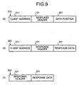
- the internal protocol analyzing unit 303 also has functions of analyzing the data 230, and creating a data 310 shown in Fig. 9(a).
- the data 310 includes the client address 211 (refer to Fig. 8(b)), the response header 121 (refer to Fig. 8(c)), and the data position 221 (refer to Fig. 8(c)).
- the cache controlling device 300 includes the cache memory 304 that is, for example, an SRAM, and has characteristics that the access time is shorter and the capacity is smaller than that of the disk 404 (refer to Fig. 6).
- a part of the data that is stored in the disk 404 is also stored in the cache memory 304.
- a storage condition of the cache memory 304 and the disk 404 are managed with the cache/actual disk controlling table 206 (refer to Fig. 4) described previously.
- the cache controlling unit 305 controls an access to the cache memory 304.
- the cache controlling device 300 includes a data adding unit 306 that adds, when the command is a read command, the data read from the cache memory 304 as a response data 321 to the client address 211 and the response header 121 to create a data 320 (see Fig. 9(b)), and transmits this data to a response data transmitting unit 307.
- the response data transmitting unit 307 has a function of transmitting a data 330 shown in Fig. 9(c) to the client address that is included in the internal header 131 (refer to Fig. 8(c)).
- the data 330 includes the response header 121 (refer to Fig. 9(b)) and a response data 321 (refer to Fig. 9(b)).
- the actual disk controlling device 400 has functions of receiving the data 230 (refer to Fig. 8(c) and 8(d)) from the storage controlling device 200, reading a data from the disk 404 (refer to Fig. 6), and writing a data to the disk 404 based on the data 230.
- Fig. 6 is a detailed block diagram of the actual disk controlling device 400.
- the actual disk controlling device 400 includes a network interface card 601 that controls a communication with the storage controlling device 200, the cache controlling device 300, one of the client devices 10 1 to 10 n, and the like in accordance with the predetermined protocol, and a network driver 402 that drive controls the network interface card 401.
- the actual disk controlling device 400 includes an internal protocol analyzing unit 403 that has a function of receiving the data 203 shown in Figs. 8(c) and 8(d) from the storage controlling device 200.
- the internal protocol analyzing unit 403 also has functions of analyzing the data 230 and creating a data 410 shown in Fig. 10(a).
- the data 410 includes the client address 211, the response header 121 (refer to Fig. 8(c)), and the data position 221 (refer to Fig. 8(c)).
- the client address 211 corresponds with the primary destination shown in Fig. 8(d).
- the actual disk controlling device 400 includes the disk 404 that is a storage medium that has characteristics of having a higher capacity and of being slower in terms of an access time than that of the cache memory 304 (refer to Fig. 5), a disk driver 405 that drive controls the disk 404, and a disk controlling unit 406 that executes read/write control of a data from and to the disk 404.
- the disk controlling unit 406 when reading data, the disk controlling unit 406 reads the data from the predetermined position in the disk 404 based on the data position 221 in the data 410 shown in Fig. 10 (a), and treat this data as a response data 420 shown in Fig. 10(b).
- the actual disk controlling device 400 includes a data adding unit 407 that adds the response data 420 (refer to Fig. 10(b)) to the client address 211 and the response header 121 shown in Fig. 10(a) to create a data 430 shown in Fig. 10(c).
- the data adding unit 407 also transmits the data 430 to a response data transmitting unit 408.
- the response data transmitting unit 408 transmits a data 440 (refer to Fig. 10(d)) to the client address that is included in the data 430 (refer to Fig. 10(c)) from the data adding unit 407.
- the response data transmitting unit 408 transmits the data 440 also to the secondary destination (the cache controlling device 300) shown in Fig. 8(d).
- Fig. 11 is a flowchart for explaining an operation of the protocol processing device 100 shown in Fig. 1.
- Fig. 12 is a flowchart for explaining an operation of the storage controlling device 200 shown in Fig. 1.
- Fig. 13 is a flowchart for explaining an operation of the cache controlling device 300 shown in Fig. 1.
- Fig. 14 is a flowchart for explaining an operation of the actual disk controlling device 400.
- step SA1 shown in Fig. 11 the external protocol processing unit 103 in the protocol processing device 100 shown in Fig. 2 determines whether the data 110 shown in Fig. 7(a) is received from one of the client devices 10 1 to 10 n (refer to Fig. 1). At this stage, the result of determination be shall be "No", and the step SA1 is repeated.
- step SB1 shown in Fig. 12 the internal protocol analyzing unit 203 in the storage controlling device 200 shown in Fig. 3 determines whether the data 130 shown in Fig. 7(c) is received from the protocol processing device 100. At this stage, the result of determination be shall be "No", and the step SB1 is repeated.
- step SC1 shown in Fig. 13 the internal protocol analyzing unit 303 in the cache controlling device 300 shown in Fig. 5 determines whether the data 230 shown in Fig. 8(c) is received from the storage controlling device 200. At this stage, the result of determination be shall be "No", and the step SC1 is repeated.
- step SD1 shown in Fig. 14 the protocol analyzing unit 403 in the actual disk controlling device 400 shown in Fig. 6 determines whether the data 230 shown in Fig. 8(c) is received from the storage controlling device 200. At this stage, the result of determination be shall be "No", and the step SD1 is repeated.
- the data 110 (refer to Fig. 7(a)) for a read operation is transmitted by, for example, the client device 10 1 to the protocol processing device 100, the data 110 is received, via the network 20, by the protocol processing device 100 shown in Fig. 2.
- the command type that is included in the request header 111 (refer to Fig. 7(a)) is a read command.
- the external protocol processing unit 103 analyzes the request header 111 in the data 110 shown in Fig. 7(a).
- the external protocol processing unit 103 creates the response header 121 shown in Fig. 7(b), and passes the data 120 to the internal protocol processing unit 104.
- the internal protocol processing unit 104 creates the internal header 131 shown in Fig. 7(c).
- the internal protocol processing unit 104 transmits the data 130 shown in Fig. 7(c), via the network 20, to the storage controlling device 200.
- the storage controlling device 200 shown in Fig. 3 receives the data 130, the result of the determination at step SB1 shown in Fig. 12 shall be "Yes”.
- the internal protocol analyzing unit 203 analyzes the internal header 131 shown in Fig. 7(c) and passes the data 210 shown in Fig. 8(a) to the data position searching unit 204.
- the data position searching unit 204 retrieves a cache range from the cache/actual disk controlling table 206 shown in Fig. 4 using the storage ID that is included in the request data 122 (refer to Fig. 8(a)) as a key. If the cache range is retrieved, the data position searching unit 204 creates the data 220 (refer to Fig. 8(b)) that includes the data position 211 (refer to Fig. 8(b)), which is a search result, and passes this data to the internal protocol transmitting unit 205.
- the internal protocol transmitting unit 205 creates the data 230 shown in Fig. 8(c).
- the internal protocol transmitting unit 205 transmits the data 230, via the network 20, to the cache controlling device 300.
- step SB6 the internal protocol transmitting unit 205 determines whether the transmission of the data 230 is completed. At this stage the result of the determination shall be "No", and the step SB6 is repeated.
- step SB6 the internal protocol transmitting unit 205 determines whether to write the data to the cache memory 304 (refer to Fig. 5). At this stage the result of the determination shall be "No", and the step SB7 is repeated.
- the internal protocol analyzing unit 303 analyzes the internal header 131 shown in Fig. 8(c), and creates the data 310 shown in Fig. 9(a).
- the internal protocol analyzing unit 303 determines the command type, i.e., whether the command is a read command or a write command, based on the result of the analysis at the step SC2. Because it is assumed here that the command is a read command, at step SC4, the internal protocol analyzing unit 303 passes the data 310 (refer to Fig. 9(a)) to the cache controlling unit 305, and directs to read the data from the cache memory 304.
- the cache controlling unit 305 reads data from the cache memory 304 based on the data position 221 (refer to Fig. 9(a)).
- the data adding unit 306 adds the response data 321 shown in Fig. 9(b) to the client address 211 and the response header 121 to create the data 320.
- the data adding unit 306 transmits the data 320 to the response data transmitting unit 307.
- the response data transmitting unit 307 creates the data 330 shown in Fig. 9(c), and transmits the created data to the client device 10 1 .
- the client 101 receives the data 330, the read operation of the data read by the cache controlling device 300 is completed.
- the data position searching unit 204 creates the data 220 (refer to Fig. 8(b)) that includes the data position 211 (refer to Fig. 8(b)), which is a search result, and passes this data to the internal protocol transmitting unit 205.
- the internal protocol transmitting unit 205 creates the data 230 shown in Fig. 8(c).
- the internal header 131 has the structure shown in Fig. 8(d).
- the internal protocol transmitting unit 205 transmits the data 230, via the network 20, to the actual disk controlling device 400.
- step SB6 the internal protocol transmitting unit 205 determines whether the transmission of the data 230 is completed. At this stage, the result of the determination shall be "No", and the step SB6 is repeated.
- the internal protocol transmitting unit 205 determines whether to write the data to the cache memory 304 (refer to Fig. 5). At this stage, the result of the determination shall be "Yes" because the internal header will be the internal header 131 shown in Fig. 8(d).
- the internal protocol transmitting unit 205 updates the cache/actual disk controlling table 206 (refer to Fig. 4) corresponding to the write operation because the data is written to the cache memory 304 as described below.
- the internal protocol analyzing unit 403 analyzes the internal header 131 shown in Fig. 8(d), and creates the data 410 shown in Fig. 10(a).
- the internal protocol analyzing unit 403 determines the command type, i.e., whether the command is a read command or a write command, based on the analysis result at the step SD2. Because the command is a read command, at step SD4, the internal protocol analyzing unit 403 passes the data 410 (refer to Fig. 10(a)) to the disk controlling unit 406, and directs to read the data from the disk 404.
- the disk controlling unit 406 reads data from the disk 404 based on the data position 221 (refer to Fig. 10(a)).
- the data adding unit 407 adds the response data 420 shown in Fig. 10(b) to the client address 211 and the response header 121 to create the data 430 shown in Fig. 10(c).
- the data adding unit 407 transmits the data 430 to the response data transmitting unit 408.
- the response data transmitting unit 408 after creating the data 440 shown in Fig. 10(d), transmits the data 440 to both the primary destination (i.e., the client 10 1 ) and the secondary destination (i.e., the cache controlling device 300) shown in Fig. 8(d).
- the client 10 1 receives the data 440, the read operation of the data by the actual disk controlling device 400 is completed.
- the cache controlling unit 305 writes the response data 420 to the cache memory 304. Consequently, because the same response data 420 exits both in the actual disk controlling device 400 and the cache controlling device 300, the data can be read from the cache controlling device 300 at the next reading.
- the data 110 (refer to Fig. 7(a)) for a write operation is transmitted to the protocol processing device 100 from, for example, the client device 10 1 , the data 110 is received, via the network 20, by the protocol processing device 100 shown in Fig. 2.
- the command type included in the request header 111 (refer to Fig. 7(a)) is a write command.
- step SA5 the internal protocol processing unit 104 transmits the data 130 shown in Fig. 7(c) to the storage controlling device 200.
- the internal protocol transmitting unit 205 transmits the data 230, via the network 20, to the actual disk controlling device 400.
- the internal header 131 in the data 230 has the structure shown in Fig. 8(d).
- the internal protocol transmitting unit 205 determines whether the transmission of the data 230 is completed. At this stage, the result of the determination shall be "No", and the step SB2 is repeated. When the transmission of the data 230 is completed, the result of the determination at the step SB6 shall be "Yes".
- the internal protocol transmitting unit 205 determines whether to write the data to the cache memory 304 (refer to Fig. 5). In this case, the result of the determination shall be "Yes" because the internal header is the internal header 131 shown in Fig. 8(d).
- the internal protocol transmitting unit 205 updates the cache/actual disk controlling table 206 (refer to Fig. 4) relating to the write because the data is written to the cache memory 304 as described below.
- the internal protocol analyzing unit 403 analyzes the internal header 131 shown in Fig. 8(d), and creates the data 410 shown in Fig. 10(a).
- the internal protocol analyzing unit 403 determines the command type, i.e., whether the command is a read command or a write command, from the result of the analysis at the step SD2. In this case, since the command is a write command, at the step SD7, the internal protocol analyzing unit 403 passes the data 410 (refer to Fig. 10(a)) to the disk controlling unit 406, and directs to write the data from the disk 404.
- the disk controlling unit 406 writes data in the disk 404 based on the data position 221 (refer to Fig. 10(a)).
- the data adding unit 407 adds the response data 420 shown in Fig. 10(b) to the client address 211 and the response header 121 to create the data 430 shown in Fig. 10(c). Then, the data adding unit 407 transmits the data 430 to the response data transmitting unit 408.
- the response data transmitting unit 408 after creating the data 440 shown in Fig. 10(c), transmits the data 440 to both the primary destination (i.e., the client 10 1 ) and the secondary destination (i.e., the cache controlling device 300) shown in Fig. 8(d).
- the client 10 1 receives the data 440, write operation of the data by the actual disk controlling device 400 is completed.
- the cache controlling unit 305 writes the response data 420 (the same data that is written into the disk 404) to the cache memory 304. Consequently, because the same response data 420 exits both in the actual disk controlling device 400 and the cache controlling device 300, the data can be read from the cache controlling device 300 at the next reading.
- the protocol processing device 100, the storage controlling device 200, the cache controlling device 300, and the actual disk controlling device 400 are prepared decentrally on the network 20 to operate controls independently from each other, the cache memory 304 shown in Fig. 5 can be used exclusively within the cache controlling device 300. Therefore, the memory area for use increases so that the cache hit rate can be increased and the access speed to a data can be improved.
- a program to realize each function of the protocol processing device 100, the storage controlling device 200, the cache controlling device 300, and the actual disk controlling device 400 my be prepared inside a storage medium 600 shown in Fig. 15 that can be read by a computer 500 shown in the same figure to achieve each function by executing the program.
- the computer 500 shown in the same figure includes a CPU (Central Processing Unit) 510, an input unit 520 such as a keyboard and a mouse, a ROM (Read Only Memory) 530 that stores various data, RAM (Random Access Memory) 540 that stores operation parameters and the like, a reading device 550 that reads a program from the storage medium 600, an output device 560 such as a display or a printer, and a bus 570 to connect each device.
- a CPU Central Processing Unit
- an input unit 520 such as a keyboard and a mouse
- ROM Read Only Memory
- RAM Random Access Memory
- a reading device 550 that reads a program from the storage medium 600
- an output device 560 such as a display or a printer
- a bus 570 to connect each device.
- the CPU 510 achieves each function described previously by executing the program after reading the program that is stored in the storage medium 600 through the reading device 550.
- the storage medium 600 includes a storage medium such as an optical disk, a flexible disk, and a hard disk.
- the same data can be transmitted to several devices with the internal header 131 from the cache controlling device 300.
- the cache memory can be used exclusively within the cache device. Therefore, the memory area for use can be increased so that the cache hit rate increase and the access speed to a data improves.
- the cache device or the disk device accesses, based on the control data, to the cache memory or the disk, and transmits an access result directly to a client device. This makes it possible to eliminate needless data transfers and to improve the access speed further.
- the disk device transmits the access result to several destinations based on a control data. This makes it possible to duplicate the data so that the system becomes more reliable.
- the cache device stores the access result in the cache memory. This makes it is possible to duplicate the data for high-speed access.
- the cache device transmits the access result to several destinations based on a control data. This makes it possible to duplicate the data so that the system becomes more reliable.
- the cache memory can be exclusively used within the cache device. Therefore, the memory area for use can be increased so that the cache hit rate increases and the access speed to a data improves.
- a storage system, a storage control program, and a method of storage control according to the present invention are useful for, for example, a storage of a data that a high access speed is required on a network.
Landscapes
- Engineering & Computer Science (AREA)
- Theoretical Computer Science (AREA)
- Physics & Mathematics (AREA)
- General Engineering & Computer Science (AREA)
- General Physics & Mathematics (AREA)
- Memory System Of A Hierarchy Structure (AREA)
- Information Retrieval, Db Structures And Fs Structures Therefor (AREA)
Abstract
Description
- The present invention relates to a storage system, a storage control program, and a method of controlling the storage to store a data on a network, and relates more specifically, to a storage system, a storage control program, and a method of controlling the storage having improved access speed to the data.
- Fig. 16 is a block diagram of a configuration of a conventional storage device. Each of client devices 101 to 10n shown in the figure is a computer terminal that has an access, via a
network 20, to astorage device 30, and performs processes such as reading of a data from thestorage device 30 and writing of a data to thestorage device 30. - The
storage device 30 is a device that includes adisk 34 and acache memory 37 as storage media, and stores large volumes of data. Anetwork interface card 31 in thestorage device 30 controls a communication with the client devices 101 to 10n in accordance with a predetermined communication protocol. Anetwork driver 32 controls thenetwork interface card 31. - The
disk 34 is a storage medium that has characteristics of having a higher capacity and of being slower in terms of an access time in comparison to thecache memory 37. Adisk driver 35 controls thedisk 34. Adisk controlling unit 36 executes read/write control of a data at thedisk 34, and RAID (Redundant Array of Independent Disks) control of thedisk 34. The RAID control means a control to enhance reliability and process speed by using more than onedisk 34 simultaneously as one disk. - The
cache memory 37 is, for example, an SRAM (Static Random Access Memory), and has characteristics of taking shorter access time but of having a smaller capacity than thedisk 34. - The
cache memory 37 stores a part of a data that is stored in thedisk 34. Acache controlling unit 38 controls an access to thecache memory 37. Aprotocol processing unit 33 controls each part corresponding to a read/write request from the client devices 101 to 10n. - When a read request is received from, for example, the client device 101, the
cache controlling unit 38 determines whether the data that is requested to be read is stored in thecache memory 37. If the data is present in the cache memory 37 (a cache hit), thecache controlling unit 38 reads the data from thecache memory 37 and passes the data to the client device 101. - On the other hand, if there is no cache hit, the
disk controlling unit 36 reads the data from thedisk 34 through thedisk driver 35, and passes the data to the client device 101. Thus, when the data is read from thedisk 34, the access time is longer than a case when the data is read from thecache memory 37. - When a write request is received from, for example, the client device 101, the
disk controlling unit 36 writes the data requested to be written to thedisk 34 through thedisk driver 35 and also passes the data to thecache controlling unit 38. Thecache controlling unit 38 writes the data to thecache memory 37 so that the same data is written to both thecache memory 37 and thedisk 34. - When writing the data, if there is no sufficient memory area in the
cache memory 37, thecache controlling unit 38 prepares an area by erasing some data in thecache memory 37, and then writes the data in the area prepared. - In the
conventional storage device 30, only one node bears all functions such as control of thedisk 34 and thecache memory 37. - The
disk 34 has a characteristic of performance that a random access speed is slow. Consequently, performance of theconventional storage device 30 degrades unless there is a cache hit in thecache memory 37. On the other hand, the performance of thenetwork 20 has been improving day-by-day; therefore, the performance of thestorage device 30 has been a bottleneck of a whole system not only in the random access, but also in a sequential access. - For example, the performance of the
disk 34 is about 50 megabyte (MB)/s to 80 MB/s in the sequential access, but is not even 10 MB/s in the random access. Moreover, an average seek time of thedisk 34 is about 4 milliseconds (ms). - Whereas, the
network 20 can give a high performance such as a bandwidth of 120 MB/s and a response time of 100 microseconds (µs) to 200 µs. If an accelerating technology such as a high-speed interconnect is applied, both the bandwidth and the response time can be improved by an order of magnitude. Thus, it is clear that the capability of thestorage device 30 is lower than the capability of thenetwork 20. - Moreover, the
storage device 30 can give full performance only when a data to be accessed is present in thecache memory 37, in other words, when there is a cache hit. A cache hit rate depends heavily on a memory size of thecache memory 37. Therefore, the larger the memory size of thecache memory 37 is, the higher the cache hit rate and the better the performance of thestorage device 30 becomes. - However, in the
conventional storage device 30 the memory size of thecache memory 37 is limited, because, only one node bears all functions such as control of thedisk 34 and thecache memory 37. Moreover, memory area usable for the cache control obviously becomes limited, because, theconventional storage device 30 consumes memory area in thecache memory 37 for control other than the cache control. - Consequently, there is a problem that the bottleneck (lowering of the access speed to a data) in a system exists because the memory area in the
cache memory 37 that is necessary for improvement of the performance is limited. - It is an object of the present invention to provide a storage device having improved access speed to a data in view of the above description.
- To achieve the above object, the present invention comprises a cache device that has a cache memory as a high-speed-access storage medium, a disk device that has a disk as a high-capacity storage medium, and a control device that accepts an access request from a client device and makes the cache device and the disk device execute a process corresponding to the access request, wherein the cache device, the disk device, and the control device are prepared decentrally on a network.
- According to the present invention, a cache device, a disk. device, and a control device are prepared decentrally on a network to operate controls independently from each other, the cache memory can be used exclusively within the cache device. Therefore, it is possible to increase the memory area for use so that the cache hit rate increase and the access speed to a data improves.
- Moreover, the present invention is a storage control program that is executed on a storage system comprising a cache device that has a cache memory as a high-speed-access storage medium, and a disk device that has a disk as a high-capacity storage medium that are prepared decentrally on a network to make a computer realize accepting an access request from a client device; creating a control data that makes the cache device and the disk device execute a process corresponding to the access request; and transmitting the control data to any one of the cache device and the disk device.
- Moreover, the present invention is a storage control method that is performed on a storage system, the storage system comprising a cache device that has a cache memory as a high-speed-access storage medium, and a disk device that has a disk as a high-capacity storage medium that are prepared decentrally on a network, comprising accepting an access request from a client device; creating a control data that makes the cache device and the disk device execute a process corresponding to the access request; and transmitting the control data to any one of the cache device and the disk device.
- According to the present invention, the cache device and the disk device are prepared decentrally on the network to operate controls independently from each other, the cache memory can be exclusively used within the cache device. Therefore, the memory area for use can be increased so that the cache hit rate increase and the access speed to a data improves.
- Fig. 1 is a block diagram of a configuration of an embodiment according to the present invention; Fig. 2 is a block diagram of a configuration of a protocol processing device 100 shown in Fig. 1; Fig. 3 is a block diagram of a configuration of a
storage controlling device 200 shown in Fig. 1; Fig. 4 is an example of contents of a cache/actual disk controlling table 206 used in the embodiment; Fig. 5 is a block diagram of a configuration of acache controlling device 300 shown in Fig. 1; Fig. 6 is a block diagram of a configuration of an actualdisk controlling device 400 shown in Fig. 1; Fig. 7 is a diagram for explaining an operation of the protocol processing device 100 shown in Fig. 1; Fig. 8 is a diagram for explaining an operation of thestorage controlling device 200 shown in Fig. 1; Fig. 9 is a diagram for explaining an operation of thecache controlling device 300 shown in Fig. 1; Fig. 10 is a diagram for explaining an operation of the actualdisk controlling device 400; Fig. 11 is a flowchart for explaining an operation of the protocol processing device 100 shown in Fig. 1; Fig. 12 a flowchart for explaining an operation of thestorage controlling device 200 shown in Fig. 1; Fig. 13 is a flowchart for explaining an operation of thecache controlling device 300 shown in Fig. 1; Fig. 14 is a flowchart that explains an operation of the actualdisk controlling device 400; Fig. 15 is a block diagram of a configuration of a variation of the same embodiment; and Fig. 16 is a block diagram of a configuration of aconventional storage device 30. - An embodiment according to the present invention is explained in detail below with reference to drawings. Fig. 1 is a block diagram of a configuration of the embodiment according to the present invention. In this diagram, identical reference numbers are given to parts that correspond to the parts shown in Fig. 16. As shown in the diagram, a protocol processing device 100, a storage controlling
device 200, acache controlling device 300, and an actualdisk controlling device 400 are connected to anetwork 20 instead of thestorage device 30 shown in Fig. 16. The protocol processing device 100, the storage controllingdevice 200, thecache controlling device 300, and the actualdisk controlling device 400 configure a storage system. - The protocol processing device 100 has functions of receiving a read/write request from one of the client devices 101 to 10n, and requesting the storage controlling
device 200, which is at subsequent stage, to process the request. - Fig. 2 is a detailed block diagram of the protocol processing device 100. The protocol processing device 100 includes a
network interface card 101 that controls a communication with the client devices 101 to 10n and thestorage controlling unit 200 in accordance with a predetermined communication protocol, and anetwork driver 102 that drive controls thenetwork interface card 101. - Moreover, the protocol processing device 100 includes an external protocol processing unit 103 that has a function of receiving a
data 110 shown in Fig. 7(a) from one of the client devices 101 to 10n. As shown in Fig. 7(a), thedata 110 includes arequest header 111 and arequest data 112. - The
request header 111 includes data relating to a command ID to identify a command (read command/write command) and a command type. On the other hand, therequest data 112 includes data relating to a storage ID that indicates a data storage position. When the command is a read command, therequest data 112 also includes data relating to an offset size of the read data. On the other hand, when the command is a write command, therequest data 112 includes data relating to an offset size of the write data, and the write data itself. - The external protocol processing unit 103 has functions of creating a
data 120 shown in Fig. 7(b) and passing the data to an internal protocol processing unit 104. Thedata 120 includes aresponse header 121 and arequest data 122. - The
response header 121 is a header format to respond to an origin of the read/write request (one of the client devices 101 to 10n) about an operating condition (succeeded or failed) of the command and the like. Theresponse header 121 includes a command ID and data relating to the operating condition (succeeded or failed) of the command, and is stored in thecache controlling device 300 and the actualdisk controlling device 400. - The
request data 122 includes data (a storage ID, and an offset size of the data (the data itself)) in a format that can be analyzed by a protocol analyzing unit 203 (refer to Fig. 3) in thestorage controlling device 200. - Referring to Fig. 2 again, the internal protocol processing unit 104 has functions of receiving the data 120 (refer to Fig. 7(b)) from the external protocol processing unit 103 and creating a
data 130 shown in Fig. 7(c), and transmitting thedata 130 to thestorage controlling device 200, which is in the subsequent stage. - The
data 130 includes aninternal header 131, the response header 121 (refer to Fig. 7(b)), and the request data 122 (refer to Fig. 7(b)). Theinternal header 131 includes data relating to an address of an origin of the read/write request (one of the client devices 101 to 10n) and a command type (read/write command). - Referring to Fig. 1, the
storage controlling device 200 has functions of receiving the data 130 (refer to Fig. 7(c)) from the protocol processing device 100, and searching a data position in the actualdisk controlling device 400 based on thedata 130 and a cache/actual disk controlling table 206 shown in Fig. 4. - The cache/actual disk controlling table 206 shown in Fig. 4 is a table that indicates a relationship of a storage ID range, an actual disk range, and a cache range. The storage ID range is a range of the storage ID described previously. The actual disk range is a range of a data position in the actual disk controlling device 400 (refer to Fig. 6), and includes data of a node ID, a disk ID, and the disk range.
- The node ID is an identifier to identify the node in the actual
disk controlling device 400. The disk ID is an identifier to identify thedisk 404. The disk range is a range of the data position in thedisk 404. - Referring to Fig. 4, the cache range is a range of a data position in the
cache controlling device 300 shown in Fig. 5, and includes data of a node ID and a memory range. The node ID is an identifier to identify the node in thecache controlling device 300. The memory range is a range of the data position in acache memory 304. - Fig. 3 is a detailed block diagram of the
storage controlling device 200. Thestorage controlling device 200 includes anetwork interface card 201 that controls a communication with the protocol processing device 100 and thecache controlling device 300 in accordance with a predetermined communication protocol, and anetwork driver 202 that drive controls thenetwork interface card 201. - Moreover, the
storage controlling device 200 includes the internalprotocol analyzing unit 203 that has a function of receiving thedata 130 shown in Fig. 7(c) from the protocol processing device 100. - In addition, the internal
protocol analyzing unit 203 has functions of analyzing thedata 130 and creating adata 210 shown in Fig. 8(a). - The
data 210 includes aclient address 211, the response header 121 (refer to Fig. 7(c)), and the request data (refer to Fig. 7(c)). Theclient address 211 is an address of the client device that is included in the internal header 131 (refer to Fig. 7(c)). - Moreover, the
storage controlling device 200 includes a dataposition searching unit 204 that has a function of retrieving a data position in the actualdisk controlling device 400 and thecache controlling device 300 from the cache/actual disk controlling table 206 (refer to Fig. 4) using the storage ID as a key. - The data position searching
unit 204 also has functions of creating adata 220 shown in Fig. 8(b), and transmitting thedata 220 to an internalprotocol transmitting unit 205. Thedata 220 includes the client address 211 (refer to Fig. 8(a)), the response header 121 (refer to Fig. 8(a)), and adata position 221. - The
data position 221 is a search result of the dataposition searching unit 204, and includes the actual disk range and the cache range shown in Fig. 4. If the data does not exist in thecache controlling device 300, only the actual disk range is included in thedata position 221, i.e., the cache range is not included. - Moreover, the
storage controlling device 200 includes the internalprotocol transmitting unit 205 that has functions of creating adata 230 shown in Fig. 8(c) based on the data 220 (refer to Fig. 8(b)) from theposition searching unit 204, and transmitting this data to thecache controlling device 300, which is at the subsequent stage, or the actual disk controlling device 400 (or only to thecache controlling device 300, or only to the actual disk controlling device 400). - The
data 230 includes the internal header 131 (a client address, and a command type: refer to Fig. 7(c)), the response header 121 (refer to Fig. 8(b)), and the data position 221 (refer to Fig. 8(b)). - If the
data 230 is to be transmitted to the actualdisk controlling device 400, theinternal header 131 includes data of a number of data transmission, a primary destination, a secondary destination, ... and a command type as shown in Fig. 8(d). - The number of data transmission is the number of destination that the data should be sent to (the client device and the cache controlling device 300) when the actual
disk controlling device 400 is accessed. The primary destination is an address of the client device (one of the client devices 101 to 10n). The secondary destination is an address of thecache controlling device 300. Thus, when the actualdisk controlling device 400 is accessed, the identical data is transmitted to both the client device and thecache controlling device 300 simultaneously. - Referring to Fig. 1 again, the
cache controlling device 300 has functions of receiving the data 230 (refer to Fig. 8(c)) from the internalprotocol transmitting unit 205, reading the data from the cache memory 304 (refer to Fig. 5), and writing the data to thecache memory 304 based on thedata 230. - Fig. 5 is a detailed block diagram of the
cache controlling device 300. Thecache controlling device 300 includes anetwork interface card 301 that controls a communication with thestorage controlling device 200, the actualdisk controlling device 400, and one of the client devices 101 to 10n in accordance with a predetermined protocol, and anetwork driver 302 that drive controls thenetwork interface card 301. - Moreover, the
cache controlling device 300 includes an internalprotocol analyzing unit 303 has a function of receiving thedata 230 shown in Fig. 8(c) from thestorage controlling device 200. The internalprotocol analyzing unit 303 also has functions of analyzing thedata 230, and creating adata 310 shown in Fig. 9(a). - The
data 310 includes the client address 211 (refer to Fig. 8(b)), the response header 121 (refer to Fig. 8(c)), and the data position 221 (refer to Fig. 8(c)). - Moreover, the
cache controlling device 300 includes thecache memory 304 that is, for example, an SRAM, and has characteristics that the access time is shorter and the capacity is smaller than that of the disk 404 (refer to Fig. 6). - A part of the data that is stored in the
disk 404 is also stored in thecache memory 304. A storage condition of thecache memory 304 and thedisk 404 are managed with the cache/actual disk controlling table 206 (refer to Fig. 4) described previously. Thecache controlling unit 305 controls an access to thecache memory 304. - Moreover, the
cache controlling device 300 includes adata adding unit 306 that adds, when the command is a read command, the data read from thecache memory 304 as aresponse data 321 to theclient address 211 and theresponse header 121 to create a data 320 (see Fig. 9(b)), and transmits this data to a response data transmitting unit 307. - The response data transmitting unit 307 has a function of transmitting a
data 330 shown in Fig. 9(c) to the client address that is included in the internal header 131 (refer to Fig. 8(c)). Thedata 330 includes the response header 121 (refer to Fig. 9(b)) and a response data 321 (refer to Fig. 9(b)). - Referring to Fig. 1, the actual
disk controlling device 400 has functions of receiving the data 230 (refer to Fig. 8(c) and 8(d)) from thestorage controlling device 200, reading a data from the disk 404 (refer to Fig. 6), and writing a data to thedisk 404 based on thedata 230. - Fig. 6 is a detailed block diagram of the actual
disk controlling device 400. The actualdisk controlling device 400 includes a network interface card 601 that controls a communication with thestorage controlling device 200, thecache controlling device 300, one of the client devices 101 to 10n, and the like in accordance with the predetermined protocol, and anetwork driver 402 that drive controls thenetwork interface card 401. - Moreover, the actual
disk controlling device 400 includes an internalprotocol analyzing unit 403 that has a function of receiving thedata 203 shown in Figs. 8(c) and 8(d) from thestorage controlling device 200. The internalprotocol analyzing unit 403 also has functions of analyzing thedata 230 and creating adata 410 shown in Fig. 10(a). - The
data 410 includes theclient address 211, the response header 121 (refer to Fig. 8(c)), and the data position 221 (refer to Fig. 8(c)). Theclient address 211 corresponds with the primary destination shown in Fig. 8(d). - Moreover, the actual
disk controlling device 400 includes thedisk 404 that is a storage medium that has characteristics of having a higher capacity and of being slower in terms of an access time than that of the cache memory 304 (refer to Fig. 5), adisk driver 405 that drive controls thedisk 404, and adisk controlling unit 406 that executes read/write control of a data from and to thedisk 404. - Specifically, when reading data, the
disk controlling unit 406 reads the data from the predetermined position in thedisk 404 based on thedata position 221 in thedata 410 shown in Fig. 10 (a), and treat this data as aresponse data 420 shown in Fig. 10(b). - Moreover, the actual
disk controlling device 400 includes adata adding unit 407 that adds the response data 420 (refer to Fig. 10(b)) to theclient address 211 and theresponse header 121 shown in Fig. 10(a) to create adata 430 shown in Fig. 10(c). Thedata adding unit 407 also transmits thedata 430 to a responsedata transmitting unit 408. - The response
data transmitting unit 408 transmits a data 440 (refer to Fig. 10(d)) to the client address that is included in the data 430 (refer to Fig. 10(c)) from thedata adding unit 407. - Moreover, the response
data transmitting unit 408 transmits thedata 440 also to the secondary destination (the cache controlling device 300) shown in Fig. 8(d). - An operation of an embodiment is explained below with reference to flowcharts shown in Figs. 11 to 14. Fig. 11 is a flowchart for explaining an operation of the protocol processing device 100 shown in Fig. 1. Fig. 12 is a flowchart for explaining an operation of the
storage controlling device 200 shown in Fig. 1. Fig. 13 is a flowchart for explaining an operation of thecache controlling device 300 shown in Fig. 1. Fig. 14 is a flowchart for explaining an operation of the actualdisk controlling device 400. - At step SA1 shown in Fig. 11, the external protocol processing unit 103 in the protocol processing device 100 shown in Fig. 2 determines whether the
data 110 shown in Fig. 7(a) is received from one of the client devices 101 to 10n (refer to Fig. 1). At this stage, the result of determination be shall be "No", and the step SA1 is repeated. - At step SB1 shown in Fig. 12, the internal
protocol analyzing unit 203 in thestorage controlling device 200 shown in Fig. 3 determines whether thedata 130 shown in Fig. 7(c) is received from the protocol processing device 100. At this stage, the result of determination be shall be "No", and the step SB1 is repeated. - At step SC1 shown in Fig. 13, the internal
protocol analyzing unit 303 in thecache controlling device 300 shown in Fig. 5 determines whether thedata 230 shown in Fig. 8(c) is received from thestorage controlling device 200. At this stage, the result of determination be shall be "No", and the step SC1 is repeated. - At step SD1 shown in Fig. 14, the
protocol analyzing unit 403 in the actualdisk controlling device 400 shown in Fig. 6 determines whether thedata 230 shown in Fig. 8(c) is received from thestorage controlling device 200. At this stage, the result of determination be shall be "No", and the step SD1 is repeated. - The data 110 (refer to Fig. 7(a)) for a read operation is transmitted by, for example, the client device 101 to the protocol processing device 100, the
data 110 is received, via thenetwork 20, by the protocol processing device 100 shown in Fig. 2. In this case, because the data is for the read operation, the command type that is included in the request header 111 (refer to Fig. 7(a)) is a read command. - When the
data 110 is received, the result of the determination at the step SA1 shown in Fig. 11 shall be "Yes". At step SA2, the external protocol processing unit 103 analyzes therequest header 111 in thedata 110 shown in Fig. 7(a). At step SA3, the external protocol processing unit 103 creates theresponse header 121 shown in Fig. 7(b), and passes thedata 120 to the internal protocol processing unit 104. - At step SA4, the internal protocol processing unit 104 creates the
internal header 131 shown in Fig. 7(c). At step SA5, the internal protocol processing unit 104 transmits thedata 130 shown in Fig. 7(c), via thenetwork 20, to thestorage controlling device 200. - When the
storage controlling device 200 shown in Fig. 3 receives thedata 130, the result of the determination at step SB1 shown in Fig. 12 shall be "Yes". At step SB2, the internalprotocol analyzing unit 203 analyzes theinternal header 131 shown in Fig. 7(c) and passes thedata 210 shown in Fig. 8(a) to the dataposition searching unit 204. - At step SB3, the data
position searching unit 204 retrieves a cache range from the cache/actual disk controlling table 206 shown in Fig. 4 using the storage ID that is included in the request data 122 (refer to Fig. 8(a)) as a key. If the cache range is retrieved, the dataposition searching unit 204 creates the data 220 (refer to Fig. 8(b)) that includes the data position 211 (refer to Fig. 8(b)), which is a search result, and passes this data to the internalprotocol transmitting unit 205. - At step SB4, the internal
protocol transmitting unit 205 creates thedata 230 shown in Fig. 8(c). At step SB5, the internalprotocol transmitting unit 205 transmits thedata 230, via thenetwork 20, to thecache controlling device 300. - At step SB6, the internal
protocol transmitting unit 205 determines whether the transmission of thedata 230 is completed. At this stage the result of the determination shall be "No", and the step SB6 is repeated. - If the transmission of the
data 230 is completed, the result of the determination at step SB6 shall be "Yes". At step SB7, the internalprotocol transmitting unit 205 determines whether to write the data to the cache memory 304 (refer to Fig. 5). At this stage the result of the determination shall be "No", and the step SB7 is repeated. - If the
cache controlling device 300 receives thedata 230, the internalprotocol analyzing unit 303 the result of the determination at step SC1 shown in Fig. 13 shall be "Yes". At step SC2, the internalprotocol analyzing unit 303 analyzes theinternal header 131 shown in Fig. 8(c), and creates thedata 310 shown in Fig. 9(a). - At step SC3, the internal
protocol analyzing unit 303 determines the command type, i.e., whether the command is a read command or a write command, based on the result of the analysis at the step SC2. Because it is assumed here that the command is a read command, at step SC4, the internalprotocol analyzing unit 303 passes the data 310 (refer to Fig. 9(a)) to thecache controlling unit 305, and directs to read the data from thecache memory 304. - Then, the
cache controlling unit 305 reads data from thecache memory 304 based on the data position 221 (refer to Fig. 9(a)). At step SC5, thedata adding unit 306 adds theresponse data 321 shown in Fig. 9(b) to theclient address 211 and theresponse header 121 to create thedata 320. Then, thedata adding unit 306 transmits thedata 320 to the response data transmitting unit 307. - At step SC6, the response data transmitting unit 307 creates the
data 330 shown in Fig. 9(c), and transmits the created data to the client device 101. When theclient 101 receives thedata 330, the read operation of the data read by thecache controlling device 300 is completed. - Moreover, when only the actual disk range is retrieved from the cache/actual disk controlling table 206 shown in Fig. 4 by the data
position searching unit 204 using the storage ID that is included in the request data 122 (refer to Fig. 7(c)) at the step SB3 shown in Fig. 12, the process described below is executed. That is, the dataposition searching unit 204 creates the data 220 (refer to Fig. 8(b)) that includes the data position 211 (refer to Fig. 8(b)), which is a search result, and passes this data to the internalprotocol transmitting unit 205. - At step SB4, the internal
protocol transmitting unit 205 creates thedata 230 shown in Fig. 8(c). Theinternal header 131 has the structure shown in Fig. 8(d). At step SB5, the internalprotocol transmitting unit 205 transmits thedata 230, via thenetwork 20, to the actualdisk controlling device 400. - At step SB6, the internal
protocol transmitting unit 205 determines whether the transmission of thedata 230 is completed. At this stage, the result of the determination shall be "No", and the step SB6 is repeated. - At step SB7, the internal
protocol transmitting unit 205 determines whether to write the data to the cache memory 304 (refer to Fig. 5). At this stage, the result of the determination shall be "Yes" because the internal header will be theinternal header 131 shown in Fig. 8(d). At step SB8, the internalprotocol transmitting unit 205 updates the cache/actual disk controlling table 206 (refer to Fig. 4) corresponding to the write operation because the data is written to thecache memory 304 as described below. - When the actual
disk controlling device 400 shown in Fig. 6 receives thedata 230, the result of the determination at step SD1 shown in Fig. 14 shall be "Yes". At step SD2, the internalprotocol analyzing unit 403 analyzes theinternal header 131 shown in Fig. 8(d), and creates thedata 410 shown in Fig. 10(a). - At step SD3, the internal
protocol analyzing unit 403 determines the command type, i.e., whether the command is a read command or a write command, based on the analysis result at the step SD2. Because the command is a read command, at step SD4, the internalprotocol analyzing unit 403 passes the data 410 (refer to Fig. 10(a)) to thedisk controlling unit 406, and directs to read the data from thedisk 404. - Then, the
disk controlling unit 406 reads data from thedisk 404 based on the data position 221 (refer to Fig. 10(a)). At step SD5, thedata adding unit 407 adds theresponse data 420 shown in Fig. 10(b) to theclient address 211 and theresponse header 121 to create thedata 430 shown in Fig. 10(c). Then, thedata adding unit 407 transmits thedata 430 to the responsedata transmitting unit 408. - At step SD6, the response
data transmitting unit 408, after creating thedata 440 shown in Fig. 10(d), transmits thedata 440 to both the primary destination (i.e., the client 101) and the secondary destination (i.e., the cache controlling device 300) shown in Fig. 8(d). When the client 101 receives thedata 440, the read operation of the data by the actualdisk controlling device 400 is completed. - Moreover, when the
cache controlling device 300 shown in Fig. 5 receives thedata 440, thecache controlling unit 305 writes theresponse data 420 to thecache memory 304. Consequently, because thesame response data 420 exits both in the actualdisk controlling device 400 and thecache controlling device 300, the data can be read from thecache controlling device 300 at the next reading. - When the data 110 (refer to Fig. 7(a)) for a write operation is transmitted to the protocol processing device 100 from, for example, the client device 101, the
data 110 is received, via thenetwork 20, by the protocol processing device 100 shown in Fig. 2. In this case, because the data is for the write operation, the command type included in the request header 111 (refer to Fig. 7(a)) is a write command. - Then, the result of the determination at the step SA1 shown in Fig. 11 shall be "Yes". Then, the processes at the steps SA2 to SA4 described previously are executed. At step SA5, the internal protocol processing unit 104 transmits the
data 130 shown in Fig. 7(c) to thestorage controlling device 200. - When the
storage controlling device 200 shown in Fig. 3 receives thedata 130, the result of the determination at step SB1 shown in Fig. 12 shall be "Yes". Then, the processes at the steps SB2 to SB4 described previously are executed. - At the step SB5, the internal
protocol transmitting unit 205 transmits thedata 230, via thenetwork 20, to the actualdisk controlling device 400. Theinternal header 131 in thedata 230 has the structure shown in Fig. 8(d). - At the step SB6, the internal
protocol transmitting unit 205 determines whether the transmission of thedata 230 is completed. At this stage, the result of the determination shall be "No", and the step SB2 is repeated. When the transmission of thedata 230 is completed, the result of the determination at the step SB6 shall be "Yes". - At the step SB7, the internal
protocol transmitting unit 205 determines whether to write the data to the cache memory 304 (refer to Fig. 5). In this case, the result of the determination shall be "Yes" because the internal header is theinternal header 131 shown in Fig. 8(d). At the step SB8, the internalprotocol transmitting unit 205, updates the cache/actual disk controlling table 206 (refer to Fig. 4) relating to the write because the data is written to thecache memory 304 as described below. - When the actual
disk controlling device 400 shown in Fig. 6 receives thedata 230, the result of the determination at the step SD1 shown in Fig. 14 shall be "Yes". At the step SD2, the internalprotocol analyzing unit 403 analyzes theinternal header 131 shown in Fig. 8(d), and creates thedata 410 shown in Fig. 10(a). - At the step SD3, the internal
protocol analyzing unit 403 determines the command type, i.e., whether the command is a read command or a write command, from the result of the analysis at the step SD2. In this case, since the command is a write command, at the step SD7, the internalprotocol analyzing unit 403 passes the data 410 (refer to Fig. 10(a)) to thedisk controlling unit 406, and directs to write the data from thedisk 404. - Then, the
disk controlling unit 406 writes data in thedisk 404 based on the data position 221 (refer to Fig. 10(a)). At the step SD5, thedata adding unit 407 adds theresponse data 420 shown in Fig. 10(b) to theclient address 211 and theresponse header 121 to create thedata 430 shown in Fig. 10(c). Then, thedata adding unit 407 transmits thedata 430 to the responsedata transmitting unit 408. - At the step SD6, the response
data transmitting unit 408, after creating thedata 440 shown in Fig. 10(c), transmits thedata 440 to both the primary destination (i.e., the client 101) and the secondary destination (i.e., the cache controlling device 300) shown in Fig. 8(d). When the client 101 receives thedata 440, write operation of the data by the actualdisk controlling device 400 is completed. - Moreover, when the
cache controlling device 300 shown in Fig. 5 receives thedata 440, thecache controlling unit 305 writes the response data 420 (the same data that is written into the disk 404) to thecache memory 304. Consequently, because thesame response data 420 exits both in the actualdisk controlling device 400 and thecache controlling device 300, the data can be read from thecache controlling device 300 at the next reading. - As explained above, according to the embodiment, the protocol processing device 100, the
storage controlling device 200, thecache controlling device 300, and the actualdisk controlling device 400 are prepared decentrally on thenetwork 20 to operate controls independently from each other, thecache memory 304 shown in Fig. 5 can be used exclusively within thecache controlling device 300. Therefore, the memory area for use increases so that the cache hit rate can be increased and the access speed to a data can be improved. - Although the embodiment according to the present invention has been explained in details with reference to the drawings, specific configuration examples are not limited to this one embodiment, and modifications in design and the like without departing from the scope of the invention can be included within the present invention.
- For example, in the embodiment described above, a program to realize each function of the protocol processing device 100, the
storage controlling device 200, thecache controlling device 300, and the actualdisk controlling device 400 my be prepared inside astorage medium 600 shown in Fig. 15 that can be read by acomputer 500 shown in the same figure to achieve each function by executing the program. - The
computer 500 shown in the same figure includes a CPU (Central Processing Unit) 510, aninput unit 520 such as a keyboard and a mouse, a ROM (Read Only Memory) 530 that stores various data, RAM (Random Access Memory) 540 that stores operation parameters and the like, areading device 550 that reads a program from thestorage medium 600, anoutput device 560 such as a display or a printer, and abus 570 to connect each device. - The
CPU 510 achieves each function described previously by executing the program after reading the program that is stored in thestorage medium 600 through thereading device 550. Thestorage medium 600 includes a storage medium such as an optical disk, a flexible disk, and a hard disk. - Furthermore, in the embodiment, a case that the same data is transmitted to several devices (for example, the client device, the
cache controlling device 300, and the like) with theinternal header 131 shown in Fig. 8(d) from the actualdisk controlling device 400 has been explained, the same data can be transmitted to several devices with theinternal header 131 from thecache controlling device 300. - As explained above, according to the present invention, because a cache device, a disk device, and a control device are prepared decentrally on a network to operate controls independently from each other, the cache memory can be used exclusively within the cache device. Therefore, the memory area for use can be increased so that the cache hit rate increase and the access speed to a data improves.
- Furthermore, according to the present invention, the cache device or the disk device accesses, based on the control data, to the cache memory or the disk, and transmits an access result directly to a client device. This makes it possible to eliminate needless data transfers and to improve the access speed further.
- Furthermore, according to the present invention, the disk device transmits the access result to several destinations based on a control data. This makes it possible to duplicate the data so that the system becomes more reliable.
- Furthermore, according to the present invention, the cache device stores the access result in the cache memory. This makes it is possible to duplicate the data for high-speed access.
- Furthermore, according to the present invention, the cache device transmits the access result to several destinations based on a control data. This makes it possible to duplicate the data so that the system becomes more reliable.
- Furthermore, according to the present invention, because the cache device and the disk device are prepared decentrally on the network to operate controls independently from each other, the cache memory can be exclusively used within the cache device. Therefore, the memory area for use can be increased so that the cache hit rate increases and the access speed to a data improves.
- As described above, a storage system, a storage control program, and a method of storage control according to the present invention are useful for, for example, a storage of a data that a high access speed is required on a network.
Claims (10)
- A storage system comprising:a cache device that has a cache memory as a high-speed-access storage medium;a disk device that has a disk as a high-capacity storage medium; anda control device that accepts an access request from a client device and makes the cache device and the disk device execute a process corresponding to the access request, wherein the cache device, the disk device, and the control device are prepared decentrally on a network.
- The storage system according to claim 1, wherein the control device transmits a control data to any one of the cache device and the disk device upon receiving the access request, and based on the control data, any one of the cache device and the disk device accesses to any one of the cache memory and the disk and transmits an access result directly to the client device.
- The storage system according to claim 1, wherein the control device transmits a control data to the disk device upon receiving the access request, and the disk device transmits an access result to a plurality of destinations based on the control data.
- The storage system according to claim 3, wherein the destinations are the client device and the cache device, and the cache device stores the access result in the cache memory.
- The storage system according to claim 1, wherein the control device transmits a control data to the cache device upon receiving the access request, and the cache device transmits an access result to a plurality of destinations based on the control data.
- A storage control program that is executed on a storage system, the storage system comprising a cache device that has a cache memory as a high-speed-access storage medium, and a disk device that has a disk as a high-capacity storage medium that are prepared decentrally on a network, the storage control program making a computer realize:accepting an access request from a client device;creating a control data that makes the cache device and the disk device execute a process corresponding to the access request; andtransmitting the control data to any one of the cache device and the disk device.
- The storage control program according to claim 6, wherein the control data is a data that directs any one of the cache device and the disk device to access any one of the cache memory and the disk, and to transmit an access result directly to the client device.
- The storage control program according to claim 6, wherein the control data is a data that directs the disk device to transmit the access result to a plurality of destinations.
- The storage control program according to claim 6, wherein the control data is a data that directs the cache device to transmit the access result to a plurality of destinations.
- A storage control method that is performed on a storage system, the storage system comprising a cache device that has a cache memory as a high-speed-access storage medium, and a disk device that has a disk as a high-capacity storage medium that are prepared decentrally on a network, comprising:accepting an access request from a client device;creating a control data that makes the cache device and the disk device execute a process corresponding to the access request; andtransmitting the control data to any one of the cache device and the disk device.
Applications Claiming Priority (1)
| Application Number | Priority Date | Filing Date | Title |
|---|---|---|---|
| PCT/JP2002/000595 WO2003065195A1 (en) | 2002-01-28 | 2002-01-28 | Storage system, storage control program, storage control method |
Publications (2)
| Publication Number | Publication Date |
|---|---|
| EP1471416A1 true EP1471416A1 (en) | 2004-10-27 |
| EP1471416A4 EP1471416A4 (en) | 2007-04-11 |
Family
ID=27639252
Family Applications (1)
| Application Number | Title | Priority Date | Filing Date |
|---|---|---|---|
| EP02716413A Withdrawn EP1471416A4 (en) | 2002-01-28 | 2002-01-28 | Storage system, storage control program, storage control method |
Country Status (4)
| Country | Link |
|---|---|
| US (1) | US7343448B2 (en) |
| EP (1) | EP1471416A4 (en) |
| JP (1) | JPWO2003065195A1 (en) |
| WO (1) | WO2003065195A1 (en) |
Families Citing this family (9)
| Publication number | Priority date | Publication date | Assignee | Title |
|---|---|---|---|---|
| EP1471416A4 (en) * | 2002-01-28 | 2007-04-11 | Fujitsu Ltd | Storage system, storage control program, storage control method |
| JP2008009829A (en) | 2006-06-30 | 2008-01-17 | Fujitsu Ltd | Storage control program, storage control device, and storage control method |
| US8341936B2 (en) | 2010-12-01 | 2013-01-01 | Ford Global Technologies, Llc | Advanced exhaust-gas sampler for exhaust sensor |
| US8769072B2 (en) | 2011-05-31 | 2014-07-01 | General Electric Company | Systems and methods for identifying foundation fieldbus linking devices |
| US8868732B2 (en) | 2011-05-31 | 2014-10-21 | General Electric Company | Systems and methods for facilitating communication with foundation fieldbus linking devices |
| US9130853B2 (en) | 2011-05-31 | 2015-09-08 | General Electric Company | Systems and methods for identifying foundation fieldbus linking devices |
| US8762528B2 (en) * | 2011-05-31 | 2014-06-24 | General Electric Company | Systems and methods for write protecting foundation fieldbus linking devices |
| US8713166B2 (en) | 2011-05-31 | 2014-04-29 | General Electric Company | Systems and methods for facilitating communication with foundation fieldbus linking devices |
| US10127236B1 (en) * | 2013-06-27 | 2018-11-13 | EMC IP Holding Company | Filesystem storing file data in larger units than used for metadata |
Citations (2)
| Publication number | Priority date | Publication date | Assignee | Title |
|---|---|---|---|---|
| WO2001095113A2 (en) * | 2000-06-06 | 2001-12-13 | Bhavsar Shyamkant R | Fabric cache |
| US20020004917A1 (en) * | 1998-06-08 | 2002-01-10 | Michael Malcolm | Network object cache engine |
Family Cites Families (11)
| Publication number | Priority date | Publication date | Assignee | Title |
|---|---|---|---|---|
| US4363095A (en) * | 1980-12-31 | 1982-12-07 | Honeywell Information Systems Inc. | Hit/miss logic for a cache memory |
| JPH05274210A (en) * | 1992-03-26 | 1993-10-22 | Nec Corp | Network file managing system |
| US6098128A (en) * | 1995-09-18 | 2000-08-01 | Cyberstorage Systems Corporation | Universal storage management system |
| JPH1173361A (en) * | 1997-08-29 | 1999-03-16 | Sharp Corp | Distributed file system, broadcasting server device for the system and client device |
| JP2000089996A (en) | 1998-09-16 | 2000-03-31 | Nec Corp | Information processor and data base system |
| US6748540B1 (en) * | 1999-06-17 | 2004-06-08 | International Business Machines Corporation | Method and apparatus for detection and notification of unauthorized access attempts in a distributed data processing system |
| JP2001005614A (en) * | 1999-06-25 | 2001-01-12 | Hitachi Ltd | Disk device and server device |
| JP2001290787A (en) | 2000-04-10 | 2001-10-19 | Ntt Communications Kk | Data distribution method and storage medium with data distribution program stored therein |
| JP2001356956A (en) * | 2000-06-15 | 2001-12-26 | Seiko Epson Corp | Cache server device and caching method |
| JP2002007304A (en) * | 2000-06-23 | 2002-01-11 | Hitachi Ltd | Computer system using storage area network and data handling method therefor |
| EP1471416A4 (en) * | 2002-01-28 | 2007-04-11 | Fujitsu Ltd | Storage system, storage control program, storage control method |
-
2002
- 2002-01-28 EP EP02716413A patent/EP1471416A4/en not_active Withdrawn
- 2002-01-28 WO PCT/JP2002/000595 patent/WO2003065195A1/en active Application Filing
- 2002-01-28 JP JP2003564722A patent/JPWO2003065195A1/en active Pending
-
2004
- 2004-06-21 US US10/871,002 patent/US7343448B2/en not_active Expired - Fee Related
Patent Citations (2)
| Publication number | Priority date | Publication date | Assignee | Title |
|---|---|---|---|---|
| US20020004917A1 (en) * | 1998-06-08 | 2002-01-10 | Michael Malcolm | Network object cache engine |
| WO2001095113A2 (en) * | 2000-06-06 | 2001-12-13 | Bhavsar Shyamkant R | Fabric cache |
Non-Patent Citations (1)
| Title |
|---|
| See also references of WO03065195A1 * |
Also Published As
| Publication number | Publication date |
|---|---|
| US20040225714A1 (en) | 2004-11-11 |
| US7343448B2 (en) | 2008-03-11 |
| JPWO2003065195A1 (en) | 2005-05-26 |
| EP1471416A4 (en) | 2007-04-11 |
| WO2003065195A1 (en) | 2003-08-07 |
Similar Documents
| Publication | Publication Date | Title |
|---|---|---|
| US7136963B2 (en) | Storage capable of cache assignment modification | |
| US6341332B2 (en) | Disk array controller with connection path formed on connection request queue basis | |
| EP1308833B1 (en) | Disk array controller | |
| CN101390060B (en) | Memory hub and method for memory sequencing | |
| US7318122B2 (en) | Disk array control device with an internal connection system for efficient data transfer | |
| US7380032B2 (en) | Storage system, and method for controlling the same | |
| US20060271590A1 (en) | Volume information analysis module and method thereof | |
| EP1471416A1 (en) | STORAGE SYSTEM, STORAGE CONTROL PROGRAM, STORAGE CONTROL METHOD | |
| US7600074B2 (en) | Controller of redundant arrays of independent disks and operation method thereof | |
| JPH076132A (en) | Interface controller | |
| US5996030A (en) | System for providing an interrogating host computer with group status information about disk devices including status information regarding disk devices not accessible to said host | |
| US6718426B2 (en) | Cache memory apparatus and central processor, hand-held device and arithmetic processor using the same | |
| JP2001344148A (en) | Boot block flash memory control circuit, ic memory card provided with it, semiconductor storage device, and boot block flash memory deleting method | |
| JP2918531B1 (en) | Cache memory controller | |
| JP2766216B2 (en) | Information processing device | |
| JP3684902B2 (en) | Disk array controller | |
| US20080140798A1 (en) | Storage adapter and method thereof | |
| KR100361657B1 (en) | Hard disk device of IDE type and controlling method thereof | |
| CN114356731A (en) | High-speed time trigger bus network data recording device | |
| KR100298287B1 (en) | Apparatus and Method of Managing Messages in a System Bus | |
| JP2006146949A (en) | Disk array control device | |
| JPH04324558A (en) | Terminal communication controller evaluating device | |
| JP2000010900A (en) | Disk array controller and disk array | |
| JPH0362264A (en) | Picture information processor | |
| JPH09198112A (en) | Controller |
Legal Events
| Date | Code | Title | Description |
|---|---|---|---|
| PUAI | Public reference made under article 153(3) epc to a published international application that has entered the european phase |
Free format text: ORIGINAL CODE: 0009012 |
|
| 17P | Request for examination filed |
Effective date: 20040721 |
|
| AK | Designated contracting states |
Kind code of ref document: A1 Designated state(s): DE FR GB |
|
| A4 | Supplementary search report drawn up and despatched |
Effective date: 20070312 |
|
| RIC1 | Information provided on ipc code assigned before grant |
Ipc: G06F 12/08 20060101AFI20070306BHEP |
|
| 17Q | First examination report despatched |
Effective date: 20070618 |
|
| RTI1 | Title (correction) |
Free format text: STORAGE SYSTEM, STORAGE CONTROL PROGRAM, STORAGE CONTROL METHOD |
|
| STAA | Information on the status of an ep patent application or granted ep patent |
Free format text: STATUS: THE APPLICATION HAS BEEN WITHDRAWN |
|
| 18W | Application withdrawn |
Effective date: 20080922 |