EP1471340B1 - Drucksensor des vibrationstyps - Google Patents
Drucksensor des vibrationstyps Download PDFInfo
- Publication number
- EP1471340B1 EP1471340B1 EP03701810A EP03701810A EP1471340B1 EP 1471340 B1 EP1471340 B1 EP 1471340B1 EP 03701810 A EP03701810 A EP 03701810A EP 03701810 A EP03701810 A EP 03701810A EP 1471340 B1 EP1471340 B1 EP 1471340B1
- Authority
- EP
- European Patent Office
- Prior art keywords
- oscillator
- pressure
- oscillatory
- sensing diaphragm
- pressure sensor
- Prior art date
- Legal status (The legal status is an assumption and is not a legal conclusion. Google has not performed a legal analysis and makes no representation as to the accuracy of the status listed.)
- Expired - Lifetime
Links
- 230000003534 oscillatory effect Effects 0.000 claims description 81
- 230000010355 oscillation Effects 0.000 claims description 34
- 239000012530 fluid Substances 0.000 claims description 28
- 230000003287 optical effect Effects 0.000 claims description 26
- 239000013307 optical fiber Substances 0.000 claims description 19
- 239000010935 stainless steel Substances 0.000 claims description 14
- 229910001220 stainless steel Inorganic materials 0.000 claims description 14
- 230000003068 static effect Effects 0.000 claims description 3
- 239000007789 gas Substances 0.000 description 25
- VYPSYNLAJGMNEJ-UHFFFAOYSA-N Silicium dioxide Chemical compound O=[Si]=O VYPSYNLAJGMNEJ-UHFFFAOYSA-N 0.000 description 24
- 238000000034 method Methods 0.000 description 23
- XUIMIQQOPSSXEZ-UHFFFAOYSA-N Silicon Chemical compound [Si] XUIMIQQOPSSXEZ-UHFFFAOYSA-N 0.000 description 16
- 229910052710 silicon Inorganic materials 0.000 description 16
- 239000010703 silicon Substances 0.000 description 16
- 229910052681 coesite Inorganic materials 0.000 description 12
- 229910052906 cristobalite Inorganic materials 0.000 description 12
- 238000005259 measurement Methods 0.000 description 12
- 239000000377 silicon dioxide Substances 0.000 description 12
- 229910052682 stishovite Inorganic materials 0.000 description 12
- 229910052905 tridymite Inorganic materials 0.000 description 12
- 239000000758 substrate Substances 0.000 description 10
- 239000011521 glass Substances 0.000 description 9
- PXHVJJICTQNCMI-UHFFFAOYSA-N nickel Substances [Ni] PXHVJJICTQNCMI-UHFFFAOYSA-N 0.000 description 9
- 239000003921 oil Substances 0.000 description 8
- 230000035945 sensitivity Effects 0.000 description 8
- 230000008859 change Effects 0.000 description 7
- 230000006698 induction Effects 0.000 description 7
- 239000004065 semiconductor Substances 0.000 description 7
- 230000000694 effects Effects 0.000 description 6
- 238000010276 construction Methods 0.000 description 5
- 239000000463 material Substances 0.000 description 5
- 230000008569 process Effects 0.000 description 5
- 230000009466 transformation Effects 0.000 description 5
- 238000004519 manufacturing process Methods 0.000 description 4
- 238000012986 modification Methods 0.000 description 4
- 230000004048 modification Effects 0.000 description 4
- 229910000986 non-evaporable getter Inorganic materials 0.000 description 4
- OKKJLVBELUTLKV-UHFFFAOYSA-N Methanol Chemical compound OC OKKJLVBELUTLKV-UHFFFAOYSA-N 0.000 description 3
- 239000002775 capsule Substances 0.000 description 3
- 238000005260 corrosion Methods 0.000 description 3
- 230000007797 corrosion Effects 0.000 description 3
- 238000002474 experimental method Methods 0.000 description 3
- 230000001939 inductive effect Effects 0.000 description 3
- 239000007788 liquid Substances 0.000 description 3
- 238000001228 spectrum Methods 0.000 description 3
- XLYOFNOQVPJJNP-UHFFFAOYSA-N water Substances O XLYOFNOQVPJJNP-UHFFFAOYSA-N 0.000 description 3
- RZVAJINKPMORJF-UHFFFAOYSA-N Acetaminophen Chemical compound CC(=O)NC1=CC=C(O)C=C1 RZVAJINKPMORJF-UHFFFAOYSA-N 0.000 description 2
- RTZKZFJDLAIYFH-UHFFFAOYSA-N Diethyl ether Chemical compound CCOCC RTZKZFJDLAIYFH-UHFFFAOYSA-N 0.000 description 2
- KRHYYFGTRYWZRS-UHFFFAOYSA-N Fluorane Chemical compound F KRHYYFGTRYWZRS-UHFFFAOYSA-N 0.000 description 2
- 230000002238 attenuated effect Effects 0.000 description 2
- 238000006243 chemical reaction Methods 0.000 description 2
- 239000004020 conductor Substances 0.000 description 2
- 230000005611 electricity Effects 0.000 description 2
- 238000009713 electroplating Methods 0.000 description 2
- 229960002050 hydrofluoric acid Drugs 0.000 description 2
- 238000002347 injection Methods 0.000 description 2
- 239000007924 injection Substances 0.000 description 2
- 238000003780 insertion Methods 0.000 description 2
- 230000037431 insertion Effects 0.000 description 2
- 230000009021 linear effect Effects 0.000 description 2
- RVZRBWKZFJCCIB-UHFFFAOYSA-N perfluorotributylamine Chemical compound FC(F)(F)C(F)(F)C(F)(F)C(F)(F)N(C(F)(F)C(F)(F)C(F)(F)C(F)(F)F)C(F)(F)C(F)(F)C(F)(F)C(F)(F)F RVZRBWKZFJCCIB-UHFFFAOYSA-N 0.000 description 2
- 238000005268 plasma chemical vapour deposition Methods 0.000 description 2
- 238000007747 plating Methods 0.000 description 2
- 239000005297 pyrex Substances 0.000 description 2
- 239000002994 raw material Substances 0.000 description 2
- 230000001105 regulatory effect Effects 0.000 description 2
- 230000002441 reversible effect Effects 0.000 description 2
- 239000000126 substance Substances 0.000 description 2
- 238000003466 welding Methods 0.000 description 2
- RYGMFSIKBFXOCR-UHFFFAOYSA-N Copper Chemical compound [Cu] RYGMFSIKBFXOCR-UHFFFAOYSA-N 0.000 description 1
- 229910000990 Ni alloy Inorganic materials 0.000 description 1
- 229910021586 Nickel(II) chloride Inorganic materials 0.000 description 1
- BOTDANWDWHJENH-UHFFFAOYSA-N Tetraethyl orthosilicate Chemical compound CCO[Si](OCC)(OCC)OCC BOTDANWDWHJENH-UHFFFAOYSA-N 0.000 description 1
- 230000009471 action Effects 0.000 description 1
- 238000009530 blood pressure measurement Methods 0.000 description 1
- KGBXLFKZBHKPEV-UHFFFAOYSA-N boric acid Chemical compound OB(O)O KGBXLFKZBHKPEV-UHFFFAOYSA-N 0.000 description 1
- 239000004327 boric acid Substances 0.000 description 1
- 238000005229 chemical vapour deposition Methods 0.000 description 1
- 239000011889 copper foil Substances 0.000 description 1
- 238000013461 design Methods 0.000 description 1
- 238000001514 detection method Methods 0.000 description 1
- 238000011161 development Methods 0.000 description 1
- 230000005674 electromagnetic induction Effects 0.000 description 1
- 238000010894 electron beam technology Methods 0.000 description 1
- 238000005530 etching Methods 0.000 description 1
- 230000005284 excitation Effects 0.000 description 1
- 239000012212 insulator Substances 0.000 description 1
- 239000002184 metal Substances 0.000 description 1
- 229910052751 metal Inorganic materials 0.000 description 1
- 239000007769 metal material Substances 0.000 description 1
- 150000002739 metals Chemical class 0.000 description 1
- 229910052759 nickel Inorganic materials 0.000 description 1
- QMMRZOWCJAIUJA-UHFFFAOYSA-L nickel dichloride Chemical compound Cl[Ni]Cl QMMRZOWCJAIUJA-UHFFFAOYSA-L 0.000 description 1
- LGQLOGILCSXPEA-UHFFFAOYSA-L nickel sulfate Chemical compound [Ni+2].[O-]S([O-])(=O)=O LGQLOGILCSXPEA-UHFFFAOYSA-L 0.000 description 1
- 229910000363 nickel(II) sulfate Inorganic materials 0.000 description 1
- 230000009972 noncorrosive effect Effects 0.000 description 1
- 229910021420 polycrystalline silicon Inorganic materials 0.000 description 1
- 229920005591 polysilicon Polymers 0.000 description 1
- 239000000376 reactant Substances 0.000 description 1
- 238000009877 rendering Methods 0.000 description 1
- 230000004044 response Effects 0.000 description 1
- 238000007789 sealing Methods 0.000 description 1
- 238000007740 vapor deposition Methods 0.000 description 1
- 238000001039 wet etching Methods 0.000 description 1
Images


Classifications
-
- G—PHYSICS
- G01—MEASURING; TESTING
- G01L—MEASURING FORCE, STRESS, TORQUE, WORK, MECHANICAL POWER, MECHANICAL EFFICIENCY, OR FLUID PRESSURE
- G01L9/00—Measuring steady of quasi-steady pressure of fluid or fluent solid material by electric or magnetic pressure-sensitive elements; Transmitting or indicating the displacement of mechanical pressure-sensitive elements, used to measure the steady or quasi-steady pressure of a fluid or fluent solid material, by electric or magnetic means
- G01L9/0001—Transmitting or indicating the displacement of elastically deformable gauges by electric, electro-mechanical, magnetic or electro-magnetic means
- G01L9/0008—Transmitting or indicating the displacement of elastically deformable gauges by electric, electro-mechanical, magnetic or electro-magnetic means using vibrations
- G01L9/0016—Transmitting or indicating the displacement of elastically deformable gauges by electric, electro-mechanical, magnetic or electro-magnetic means using vibrations of a diaphragm
- G01L9/0017—Optical excitation or measuring
Landscapes
- Physics & Mathematics (AREA)
- General Physics & Mathematics (AREA)
- Measuring Fluid Pressure (AREA)
Claims (6)
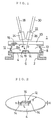
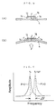
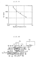
- Schwingungs-Drucksensor (1), umfassend eine druckaufnehmende Membran (4), an deren hintere Seitenfläche ein Fluiddruck angelegt wird, einen Oszillator (12), der an einer vorderen Seitenfläche der druckaufnehmenden Membran vorgesehen ist, einen Wandkörper (8), der so angeordnet ist, dass er den Oszillator umgibt, und einen lichtübertragenden Teil (20), der einen Öffnungsteil des Wandkörpers auf luftdichte Weise verschließt, so dass ein Innenraum, in dem der Oszillator installiert ist, eine Vakuumkammer (10) bildet, wobei der Schwingungs-Drucksensor ein optisches Messmittel (22) aufweist, in dem ein einfallender Lichtstrahl durch den lichtübertragenden Teil (20) gelangen kann, um in die Vakuumkammer (10) einzudringen, wobei der Lichtstrahl, der von einer Oszillationsplatte (16) reflektiert wird, die veranlasst wird, durch eine externe Vibrationskraft zu schwingen, die von außerhalb der Vakuumkammer angelegt wird, durch den lichtübertragenden Teil aus der Vakuumkammer austreten kann, und der reflektierte Lichtstrahl erfasst wird, um die Resonanzfrequenz des Oszillators (12) zu messen, so dass der Fluiddruck, der von der druckaufnehmenden Membran (4) erfasst wird, von der Resonanzfrequenz erhalten wird, dadurch gekennzeichnet, dass ein piezoelektrisches Betätigungselement (57) an einer Außenfläche der druckaufnehmenden Membran (4), dem Wandkörper (8) oder dem lichtübertragenen Teil (20) befestigt ist, so dass der Oszillator (12) der druckaufnehmenden Membran (4) veranlasst wird, mit der Oszillation des piezoelektrischen Betätigungselements zu schwingen, und wobei die druckaufnehmende Membran aus Edelstahl besteht.
- Schwingungs-Drucksensor (1), umfassend eine druckaufnehmende Membran (4), an deren hintere Seitenfläche ein Fluiddruck angelegt wird, einen Oszillator (12), der an einer vorderen Seitenfläche der druckaufnehmenden Membran vorgesehen ist, einen Wandkörper (8), der so angeordnet ist, dass er den Oszillator umgibt, und einen lichtübertragenden Teil (20), der einen Öffnungsteil des Wandkörpers auf luftdichte Weise verschließt, so dass ein Innenraum, in dem der Oszillator installiert ist, eine Vakuumkammer (10) bildet, wobei der Schwingungs-Drucksensor ein optisches Messmittel (22) aufweist, in dem ein einfallender Lichtstrahl durch den lichtübertragenden Teil (20) gelangen kann, um in die Vakuumkammer (10) einzudringen, wobei der Lichtstrahl, der von einer Oszillationsplatte (16) reflektiert wird, die veranlasst wird, durch eine externe Vibrationskraft zu schwingen, die von außerhalb der Vakuumkammer angelegt wird, durch den lichtübertragenden Teil aus der Vakuumkammer austreten kann, und der reflektierte Lichtstrahl erfasst wird, um die Resonanzfrequenz des Oszillators (12) zu messen, so dass der Fluiddruck, der von der druckaufnehmenden Membran (4) erfasst wird, von der Resonanzfrequenz erhalten wird, dadurch gekennzeichnet, dass eine Wechselstromspannung zwischen einem Elektrodenteil (76), das extern von dem lichtübertragenden Teil (20) angeordnet ist, und der druckaufnehmenden Membran (4) angelegt ist, und die Membran durch die statische elektrische Kraft einer erzwungenen Oszillation unterliegt, so dass der Oszillator (12) indirekt veranlasst wird, mitzuschwingen und wobei die druckaufnehmende Membran aus Edelstahl besteht.
- Schwingungs-Drucksensor (1) nach Anspruch 1 oder 2, wobei der Oszillator eine Brückenstruktur aufweist, in der der Oszillator ein Paar Basisstützen (14, 14) umfasst, die symmetrisch auf einer Fläche der druckaufnehmenden Membran und der Oszillationsplatte (16), die die Basisstützen überbrückt, platziert sind.
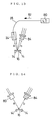
- Schwingungs-Drucksensor (1) nach Anspruch 1 oder 2, wobei das optische Messmittel (22) eine optische Faser (28) zum Einfallen des Lichtstrahls, eine Einfallslinse (24), die veranlasst, dass der einfallende Lichtstrahl auf der Fläche des Oszillators fokussiert wird, eine Reflektionslinse (26) zum Konvergieren des Strahls, der von dem Oszillator reflektiert worden ist, und eine optische Faser (30) für die Reflektion zum Leiten des reflektierten Strahls umfasst.
- Schwingungs-Drucksensor (1) nach Anspruch 1 oder 2, wobei das optische Messmittel (22) einen Laser-Doppler-Schwingungsmesser (24) umfasst, um den Strahl aufzunehmen, der vom Oszillator (12) reflektiert wird.
- Schwingungs-Drucksensor (1) nach Anspruch 1 oder 2, wobei das optische Messmittel (22) ein halbgeteiltes lichtaufnehmendes Element (84) umfasst, wobei Änderungen des reflektierten Strahls von einem Differenzausgang des halbgeteilten lichtaufnehmenden Elements erfasst werden, so dass die Resonanzfrequenz des Oszillators (12) erhalten wird.
Applications Claiming Priority (3)
| Application Number | Priority Date | Filing Date | Title |
|---|---|---|---|
| JP2002011528 | 2002-01-21 | ||
| JP2002011528A JP4082907B2 (ja) | 2002-01-21 | 2002-01-21 | 振動形圧力センサ |
| PCT/JP2003/000442 WO2003062778A1 (fr) | 2002-01-21 | 2003-01-20 | Capteur de pression de type vibrant |
Publications (3)
| Publication Number | Publication Date |
|---|---|
| EP1471340A1 EP1471340A1 (de) | 2004-10-27 |
| EP1471340A4 EP1471340A4 (de) | 2006-09-06 |
| EP1471340B1 true EP1471340B1 (de) | 2008-09-24 |
Family
ID=27606017
Family Applications (1)
| Application Number | Title | Priority Date | Filing Date |
|---|---|---|---|
| EP03701810A Expired - Lifetime EP1471340B1 (de) | 2002-01-21 | 2003-01-20 | Drucksensor des vibrationstyps |
Country Status (5)
| Country | Link |
|---|---|
| US (1) | US6938489B2 (de) |
| EP (1) | EP1471340B1 (de) |
| JP (1) | JP4082907B2 (de) |
| DE (1) | DE60323728D1 (de) |
| WO (1) | WO2003062778A1 (de) |
Cited By (2)
| Publication number | Priority date | Publication date | Assignee | Title |
|---|---|---|---|---|
| RU2470274C1 (ru) * | 2011-07-29 | 2012-12-20 | Государственное учреждение "Арктический и Антарктический научно-исследовательский Институт" (ГУ "ААНИИ") | Способ и устройство для измерения давления внутри трубопроводов |
| RU2521275C1 (ru) * | 2013-02-15 | 2014-06-27 | Федеральное государственное бюджетное учреждение науки Институт проблем управления им. В.А. Трапезникова Российской академии наук | Устройство для измерения давления |
Families Citing this family (19)
| Publication number | Priority date | Publication date | Assignee | Title |
|---|---|---|---|---|
| US7162918B2 (en) * | 2001-05-15 | 2007-01-16 | Baker Hughes Incorporated | Method and apparatus for downhole fluid characterization using flexural mechanical resonators |
| US7444880B2 (en) * | 2003-12-12 | 2008-11-04 | California Institute Of Technology | Method and apparatus for measuring the mechanical response of micro-electro-mechanical systems |
| KR20050111662A (ko) * | 2004-05-21 | 2005-11-28 | 삼성전자주식회사 | 압력 및 진동감지장치 |
| ITTO20050316A1 (it) * | 2005-05-10 | 2006-11-11 | Varian Spa | Sensore di pressione |
| US20070236213A1 (en) * | 2006-03-30 | 2007-10-11 | Paden Bradley E | Telemetry method and apparatus using magnetically-driven mems resonant structure |
| US7465916B2 (en) | 2006-10-19 | 2008-12-16 | Fujikura Ltd. | Optical detection sensor |
| US7615736B2 (en) | 2007-05-31 | 2009-11-10 | Fujikura Ltd. | Optical sensor |
| US20100233353A1 (en) * | 2009-03-16 | 2010-09-16 | Applied Materials, Inc. | Evaporator, coating installation, and method for use thereof |
| KR101253334B1 (ko) * | 2011-10-07 | 2013-04-11 | 숭실대학교산학협력단 | 안압 센서 및 그 제조 방법 |
| US20130300571A1 (en) * | 2012-04-18 | 2013-11-14 | Farrokh Mohamadi | Interrogation of active and passive proppants for real-time monitoring of fractured wells |
| TWI477752B (zh) * | 2012-05-02 | 2015-03-21 | Nat Applied Res Laboratories | Piezoelectric vacuum gauge and its measuring method |
| GB2509105B (en) * | 2012-12-20 | 2017-02-22 | Oxsensis Ltd | Mechanical resonator sensor |
| US9454158B2 (en) | 2013-03-15 | 2016-09-27 | Bhushan Somani | Real time diagnostics for flow controller systems and methods |
| EP3074360B1 (de) * | 2013-11-29 | 2020-01-01 | Calix Ltd | Verfahren zur herstellung von portlandzement |
| US9671303B2 (en) | 2015-03-10 | 2017-06-06 | Ford Global Technologies, Llc | Method and system for laser pressure transducer |
| US20180164134A1 (en) * | 2015-07-28 | 2018-06-14 | Nazhiyuan Technology (Tangshan), LLC. | Pneumatic sensor in electronic cigarette, device for processing airflow, and electronic cigarette |
| US10983537B2 (en) | 2017-02-27 | 2021-04-20 | Flow Devices And Systems Inc. | Systems and methods for flow sensor back pressure adjustment for mass flow controller |
| LU102636B1 (en) * | 2021-03-04 | 2022-09-05 | Stratec Se | Sensor for determining the oscillating frequency in a fluidic oscillating nozzle and a method using the sensor |
| CN116222870B (zh) * | 2023-05-09 | 2023-07-11 | 山东杨嘉汽车制造有限公司 | 一种干粉罐车罐体及其监控系统 |
Citations (5)
| Publication number | Priority date | Publication date | Assignee | Title |
|---|---|---|---|---|
| JPS57153233A (en) * | 1981-03-18 | 1982-09-21 | Matsushita Electric Ind Co Ltd | Water pressure detecting device |
| EP0266974A2 (de) * | 1986-11-03 | 1988-05-11 | Nortel Networks Corporation | Messfühlervorrichtung |
| US5188983A (en) * | 1990-04-11 | 1993-02-23 | Wisconsin Alumni Research Foundation | Polysilicon resonating beam transducers and method of producing the same |
| US5442963A (en) * | 1991-08-23 | 1995-08-22 | Solartron Group Limited | Temperature-compensated vibrating beam microsensor |
| JPH10132691A (ja) * | 1996-10-31 | 1998-05-22 | Hitachi Ltd | ダイアフラム |
Family Cites Families (6)
| Publication number | Priority date | Publication date | Assignee | Title |
|---|---|---|---|---|
| JPS56122925A (en) | 1980-02-29 | 1981-09-26 | Shimadzu Corp | Sensor |
| GB2223582B (en) * | 1988-10-04 | 1992-06-17 | Stc Plc | Transducer device |
| US5090254A (en) * | 1990-04-11 | 1992-02-25 | Wisconsin Alumni Research Foundation | Polysilicon resonating beam transducers |
| JPH076852A (ja) | 1993-06-15 | 1995-01-10 | Toshiba Corp | 避雷装置及びその劣化検出方法 |
| US5844236A (en) | 1997-01-17 | 1998-12-01 | Honeywell Inc. | Multi-wavelength optical drive/sense readout for resonant microstructures |
| JP2002267558A (ja) | 2001-03-14 | 2002-09-18 | Akebono Brake Ind Co Ltd | テレメトリック圧力センサ |
-
2002
- 2002-01-21 JP JP2002011528A patent/JP4082907B2/ja not_active Expired - Fee Related
-
2003
- 2003-01-20 US US10/486,331 patent/US6938489B2/en not_active Expired - Lifetime
- 2003-01-20 WO PCT/JP2003/000442 patent/WO2003062778A1/ja active IP Right Grant
- 2003-01-20 DE DE60323728T patent/DE60323728D1/de not_active Expired - Fee Related
- 2003-01-20 EP EP03701810A patent/EP1471340B1/de not_active Expired - Lifetime
Patent Citations (5)
| Publication number | Priority date | Publication date | Assignee | Title |
|---|---|---|---|---|
| JPS57153233A (en) * | 1981-03-18 | 1982-09-21 | Matsushita Electric Ind Co Ltd | Water pressure detecting device |
| EP0266974A2 (de) * | 1986-11-03 | 1988-05-11 | Nortel Networks Corporation | Messfühlervorrichtung |
| US5188983A (en) * | 1990-04-11 | 1993-02-23 | Wisconsin Alumni Research Foundation | Polysilicon resonating beam transducers and method of producing the same |
| US5442963A (en) * | 1991-08-23 | 1995-08-22 | Solartron Group Limited | Temperature-compensated vibrating beam microsensor |
| JPH10132691A (ja) * | 1996-10-31 | 1998-05-22 | Hitachi Ltd | ダイアフラム |
Cited By (2)
| Publication number | Priority date | Publication date | Assignee | Title |
|---|---|---|---|---|
| RU2470274C1 (ru) * | 2011-07-29 | 2012-12-20 | Государственное учреждение "Арктический и Антарктический научно-исследовательский Институт" (ГУ "ААНИИ") | Способ и устройство для измерения давления внутри трубопроводов |
| RU2521275C1 (ru) * | 2013-02-15 | 2014-06-27 | Федеральное государственное бюджетное учреждение науки Институт проблем управления им. В.А. Трапезникова Российской академии наук | Устройство для измерения давления |
Also Published As
| Publication number | Publication date |
|---|---|
| EP1471340A4 (de) | 2006-09-06 |
| WO2003062778A1 (fr) | 2003-07-31 |
| US6938489B2 (en) | 2005-09-06 |
| JP2003214966A (ja) | 2003-07-30 |
| DE60323728D1 (de) | 2008-11-06 |
| US20040231424A1 (en) | 2004-11-25 |
| JP4082907B2 (ja) | 2008-04-30 |
| EP1471340A1 (de) | 2004-10-27 |
Similar Documents
| Publication | Publication Date | Title |
|---|---|---|
| EP1471340B1 (de) | Drucksensor des vibrationstyps | |
| US6647778B2 (en) | Integrated microtube sensing device | |
| US7895905B2 (en) | Flowmeter | |
| Enoksson et al. | A silicon resonant sensor structure for Coriolis mass-flow measurements | |
| US4897541A (en) | Sensors for detecting electromagnetic parameters utilizing resonating elements | |
| US8272274B2 (en) | Microfluidic device and methods of operation and making | |
| US7779700B2 (en) | Pressure sensor | |
| US7921737B2 (en) | Microfluidic device and method of operation | |
| GB2221302A (en) | Coriolis-effect fluid mass flow and density sensor made by a micromachining method | |
| KR20010071501A (ko) | 광섬유 압력 센서 및 그 변형, 및 가요성 반사막을제조하는 방법 | |
| US5101664A (en) | Optical pressure transducer | |
| CN108593956B (zh) | 双模式微流速计及其制备方法 | |
| EP1722210A2 (de) | Drucksensor mit schwingendem Element | |
| Sievilä et al. | Fabrication and characterization of an ultrasensitive acousto-optical cantilever | |
| Josserand et al. | PVF2 velocity hydrophones | |
| US20070158554A1 (en) | Probe for probe microscope using transparent substrate, method of producing the same, and probe microscope device | |
| US6722209B1 (en) | Coriolis force type flow meter using optical interferometer | |
| Najmzadeh et al. | A silicon straight tube fluid density sensor | |
| Yu et al. | A resonant high-pressure sensor based on integrated resonator-diaphragm structure | |
| JP3008986B2 (ja) | パラメータの値を求める方法 | |
| Hornung et al. | Micromachined ultrasound-based Proximity sensors | |
| US11287334B1 (en) | Optomechanical pressure measurement system and method using the vibrational modes of a membrane | |
| JPS6127694B2 (de) | ||
| JPS605883B2 (ja) | 渦流量計 | |
| Sievila et al. | Optically detected, framed silicon cantilever for high precision acoustic sensing |
Legal Events
| Date | Code | Title | Description |
|---|---|---|---|
| PUAI | Public reference made under article 153(3) epc to a published international application that has entered the european phase |
Free format text: ORIGINAL CODE: 0009012 |
|
| 17P | Request for examination filed |
Effective date: 20031210 |
|
| AK | Designated contracting states |
Kind code of ref document: A1 Designated state(s): AT BE BG CH CY CZ DE DK EE ES FI FR GB GR HU IE IT LI LU MC NL PT SE SI SK TR |
|
| A4 | Supplementary search report drawn up and despatched |
Effective date: 20060803 |
|
| 17Q | First examination report despatched |
Effective date: 20061221 |
|
| GRAP | Despatch of communication of intention to grant a patent |
Free format text: ORIGINAL CODE: EPIDOSNIGR1 |
|
| GRAS | Grant fee paid |
Free format text: ORIGINAL CODE: EPIDOSNIGR3 |
|
| GRAA | (expected) grant |
Free format text: ORIGINAL CODE: 0009210 |
|
| AK | Designated contracting states |
Kind code of ref document: B1 Designated state(s): CH DE FR GB IT LI NL |
|
| REG | Reference to a national code |
Ref country code: GB Ref legal event code: FG4D |
|
| REG | Reference to a national code |
Ref country code: CH Ref legal event code: EP Ref country code: CH Ref legal event code: NV Representative=s name: BOVARD AG PATENTANWAELTE |
|
| REF | Corresponds to: |
Ref document number: 60323728 Country of ref document: DE Date of ref document: 20081106 Kind code of ref document: P |
|
| PLBE | No opposition filed within time limit |
Free format text: ORIGINAL CODE: 0009261 |
|
| STAA | Information on the status of an ep patent application or granted ep patent |
Free format text: STATUS: NO OPPOSITION FILED WITHIN TIME LIMIT |
|
| REG | Reference to a national code |
Ref country code: CH Ref legal event code: PL |
|
| 26N | No opposition filed |
Effective date: 20090625 |
|
| GBPC | Gb: european patent ceased through non-payment of renewal fee |
Effective date: 20090120 |
|
| NLV4 | Nl: lapsed or anulled due to non-payment of the annual fee |
Effective date: 20090801 |
|
| PG25 | Lapsed in a contracting state [announced via postgrant information from national office to epo] |
Ref country code: DE Free format text: LAPSE BECAUSE OF NON-PAYMENT OF DUE FEES Effective date: 20090801 Ref country code: LI Free format text: LAPSE BECAUSE OF NON-PAYMENT OF DUE FEES Effective date: 20090131 Ref country code: CH Free format text: LAPSE BECAUSE OF NON-PAYMENT OF DUE FEES Effective date: 20090131 |
|
| REG | Reference to a national code |
Ref country code: FR Ref legal event code: ST Effective date: 20091030 |
|
| PG25 | Lapsed in a contracting state [announced via postgrant information from national office to epo] |
Ref country code: NL Free format text: LAPSE BECAUSE OF NON-PAYMENT OF DUE FEES Effective date: 20090801 Ref country code: GB Free format text: LAPSE BECAUSE OF NON-PAYMENT OF DUE FEES Effective date: 20090120 |
|
| PG25 | Lapsed in a contracting state [announced via postgrant information from national office to epo] |
Ref country code: FR Free format text: LAPSE BECAUSE OF NON-PAYMENT OF DUE FEES Effective date: 20090202 |
|
| PG25 | Lapsed in a contracting state [announced via postgrant information from national office to epo] |
Ref country code: IT Free format text: LAPSE BECAUSE OF NON-PAYMENT OF DUE FEES Effective date: 20090120 |