EP1471322B1 - Verfahren zur Herstellung eines Wärmetauschers - Google Patents
Verfahren zur Herstellung eines Wärmetauschers Download PDFInfo
- Publication number
- EP1471322B1 EP1471322B1 EP04001346.8A EP04001346A EP1471322B1 EP 1471322 B1 EP1471322 B1 EP 1471322B1 EP 04001346 A EP04001346 A EP 04001346A EP 1471322 B1 EP1471322 B1 EP 1471322B1
- Authority
- EP
- European Patent Office
- Prior art keywords
- heat exchanger
- headers
- blocks
- another
- header
- Prior art date
- Legal status (The legal status is an assumption and is not a legal conclusion. Google has not performed a legal analysis and makes no representation as to the accuracy of the status listed.)
- Expired - Lifetime
Links
Images

Classifications
-
- F—MECHANICAL ENGINEERING; LIGHTING; HEATING; WEAPONS; BLASTING
- F28—HEAT EXCHANGE IN GENERAL
- F28D—HEAT-EXCHANGE APPARATUS, NOT PROVIDED FOR IN ANOTHER SUBCLASS, IN WHICH THE HEAT-EXCHANGE MEDIA DO NOT COME INTO DIRECT CONTACT
- F28D9/00—Heat-exchange apparatus having stationary plate-like or laminated conduit assemblies for both heat-exchange media, the media being in contact with different sides of a conduit wall
- F28D9/0031—Heat-exchange apparatus having stationary plate-like or laminated conduit assemblies for both heat-exchange media, the media being in contact with different sides of a conduit wall the conduits for one heat-exchange medium being formed by paired plates touching each other
- F28D9/0043—Heat-exchange apparatus having stationary plate-like or laminated conduit assemblies for both heat-exchange media, the media being in contact with different sides of a conduit wall the conduits for one heat-exchange medium being formed by paired plates touching each other the plates having openings therein for circulation of at least one heat-exchange medium from one conduit to another
-
- F—MECHANICAL ENGINEERING; LIGHTING; HEATING; WEAPONS; BLASTING
- F28—HEAT EXCHANGE IN GENERAL
- F28F—DETAILS OF HEAT-EXCHANGE AND HEAT-TRANSFER APPARATUS, OF GENERAL APPLICATION
- F28F9/00—Casings; Header boxes; Auxiliary supports for elements; Auxiliary members within casings
- F28F9/02—Header boxes; End plates
- F28F9/0246—Arrangements for connecting header boxes with flow lines
-
- F—MECHANICAL ENGINEERING; LIGHTING; HEATING; WEAPONS; BLASTING
- F28—HEAT EXCHANGE IN GENERAL
- F28F—DETAILS OF HEAT-EXCHANGE AND HEAT-TRANSFER APPARATUS, OF GENERAL APPLICATION
- F28F9/00—Casings; Header boxes; Auxiliary supports for elements; Auxiliary members within casings
- F28F9/26—Arrangements for connecting different sections of heat-exchange elements, e.g. of radiators
Definitions
- the invention relates to a method for producing a plate heat exchanger from a plurality of heat exchanger blocks according to the preamble of claim 1.
- WO 98/03831 shows a heat exchanger with the features mentioned in the preamble of claim 1.
- the heat exchanger block of a plate heat exchanger consists of several layers of heat exchange passages, which are each delimited by separating plates against each other. End strips and cover plates form the outer frame of the heat exchanger block. Within a layer, further separating strips can be provided which separate heat exchange passages for different material flows from one another. By means of a suitable arrangement of separating strips, plate heat exchangers can be used for the simultaneous heat exchange of many fluid streams.
- the initially made of loose components heat exchanger block is then soldered in a brazing furnace, so that all components are sealed together.
- headers are welded over the inlet and outlet openings of the heat exchange passages, which are provided with a fluid connection.
- Semi-cylindrical trays are usually used as headers.
- the fluid connection is formed by pipe sockets, which are arranged in the half-cylinder jacket of the header with respect to the inlet and outlet openings of the heat exchange passages. At this pipe socket, the pipes for the incoming and outgoing fluid flows are connected.
- each heat exchanger block is provided with the corresponding headers and the pipe sockets welded thereto.
- a manifold is provided to which the corresponding pipe sockets connected become.
- the piping of the heat exchanger blocks with each other and with the corresponding connecting lines is thus extremely complex and expensive.
- Object of the present invention is therefore to develop a method for producing a plate heat exchanger from a plurality of heat exchanger blocks, in which the cost of tubing is as low as possible.
- the plate heat exchanger is produced from a plurality of heat exchanger blocks.
- Each heat exchanger block has a plurality of heat exchange passages.
- the heat exchange passages can be divided into specific groups, the heat exchange passages of a group each serving to guide a particular fluid flow. Via the inlet and outlet openings in the heat exchange passages of a group headers are each mounted so that a flow connection between these passages is made.
- the header sometimes referred to as a collector covers a part of a heat exchanger block side and forms with this a closed space into which the inlet or outlet openings of a group of heat exchange passages open.
- the heat exchanger blocks are arranged side by side so that at least one header of the one heat exchanger block is adjacent to or facing a header of another heat exchanger block.
- the heat exchanger blocks are slightly spaced apart.
- the two headers are then provided at their facing sides with openings and interconnected so that a flow connection between the two headers is formed.
- a common header is formed for both heat exchanger blocks, via which, for example, a fluid supplied to this common header is distributed to the corresponding heat exchange passages of both heat exchanger blocks.
- the individual heat exchanger blocks are connected according to the invention by direct connection of their respective headers to a common header on the flow side. It is no longer necessary to provide each individual header with a separate fluid connection or pipe socket and to pipe the individual fluid connections with each other.
- the heat exchanger blocks are arranged side by side so that the adjacent sides of two headers are disposed substantially perpendicular to the side of the respective heat exchanger block over which the header extends.
- the openings of the headers which serve as their flow connection, are arranged in a plane which is substantially perpendicular to the plane in which the respective inlet and outlet openings are located in the heat exchange passages. That is, the flow connection of the two headers is currently not directly opposite the respective inlet and outlet openings of the heat exchange passages.
- the fluid connection i. the opening of the header to the pipelines supplying and discharging the respective fluid stream is preferably likewise arranged in a plane which is substantially perpendicular to the plane in which the corresponding inlet and outlet openings are located in the heat exchange passages. That is, the fluid port is currently not directly opposite the inlet and outlet openings.
- all fluid connections can be provided on two opposite sides of the individual heat exchanger blocks.
- the heat exchanger blocks are designed so that all fluid connections are located on the same side of the respective heat exchanger block.
- the pipelines for supplying and discharging the material flows brought into heat exchange with each other must therefore no longer be carried around the heat exchanger block consuming.
- the piping effort is significantly reduced.
- the headers preferably have a semicircular cross-section, in particular semi-cylindrical shells have proven to be suitable as headers.
- the two semicircular base surfaces are preferably provided with openings and connected to each other. For reasons of strength, it may be advantageous to orient the base of a header opposite the flow connection of the two headers not vertically, but for example obliquely to the half-cylinder shell.
- the common header resulting from the joining of two adjacent headers according to the invention is provided with a fluid port located in one side of the common header which is substantially perpendicular to those sides of the two heat exchanger blocks over which the two headers extend.
- the fluid connection is not provided in the half-cylinder shell of the common header, but in one of the semi-circular base surfaces, which are oriented perpendicular to the cylinder axis.
- the opening made in the header extends over the entire cross section of the header and, particularly preferably, is connected to the adjacent header while maintaining the cross section.
- the result is a continuous header extending over two or more heat exchanger blocks.
- the heat exchanger blocks are arranged next to each other at a distance, so that a gap remains between the heat exchanger blocks.
- the heat exchanger blocks are connected together with the installation of a spacer, usually welded together.
- a spacer for example, a correspondingly shaped sheet or strip can be used.
- the spacer is arranged in the region of the common header such that the side of the header facing the heat exchanger blocks is completely covered by the spacer in the area of the gap.
- the space inside the common header is limited by the header itself, for example, a semi-tubular shell, the side walls of the heat exchanger blocks, and a part of the spacer.
- the common header serves not only to distribute the supplied fluid flow to the heat exchange passages or to collect the fluid exiting the heat exchange passages, but also to supply and discharge the respective fluid streams to and from the individual heat exchanger blocks.
- this dual function is further taken into account by providing means for the flow guidance of the fluid supplied or discharged via the fluid connection within the header.
- a guide plate can be arranged within the header, which divides the space within the header into a flow region, which preferably serves for the supply and discharge of the fluid, and into a distribution region, in which the flow is calmed and as uniform a distribution as possible of the fluid takes place on the heat exchange passages.
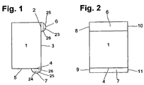
- FIG. 1 and 2 is a heat exchanger block 1 with headers 6, 7 shown schematically.
- the heat exchanger block 1 has a plurality of heat exchange passages, which are not shown in the figures for the sake of clarity.
- the inlet and outlet openings of a group of heat exchange passages are located in the region 2 on a side wall 3 of the heat exchanger block 1 and in the region 4 on the bottom 5 of the heat exchanger block 1.
- headers 6, 7 welded.
- the headers 6, 7 are designed as semi-cylindrical shells with bases 8, 9, 10, 11.
- baffles 23, 24 are arranged, which divide the space within the header 6, 7 in a flow region 25 and a distribution region 26.
- the baffles 23, 24 are provided with a plurality of openings, so that a gas and liquid exchange between the flow region 25 and the distribution region 26 is possible.
- FIG. 3 shows an intermediate stage in the manufacture of a plate heat exchanger according to the invention.
- the heat exchanger blocks 1 a, 1 b are identical to that in the Figures 1 and 2 constructed heat exchanger block 1 constructed.
- the heat exchanger blocks 1a, 1b are first subjected to a leak test and a pressure resistance test with their respective headers 6a, 6b, 7a, 7b. After successful testing, all bases 8a, 9a, 10a, 11a of the headers 6a and 7a of the heat exchanger block 1a and the bases 8b, 9b of the headers 6b, 7b of the heat exchanger block 1b are separated. On the two mutually facing sides of the headers 6a, 6b, 7a, 7b, the separation takes place, as in FIG. 3 represented by dashed lines 20, obliquely to the axis of the semi-cylindrical headers 6a, 7a, 6b, 7b. The bases 8a, 9a of the heat exchanger block 1a are cut perpendicular to the axis of the semi-cylindrical headers 6a, 7a.
- the two heat exchanger blocks 1 a, 1 b are then welded together at their lower end with a metal sheet 16.
- the U-shaped plate 16 is secured to the heat exchanger blocks 1a, 1b so that the base of the U-shaped plate 16 joins the bottoms 5a, 5b of the two blocks 1a, 1b to provide a continuous plane.
- the two heat exchanger blocks 1 a, 1 b are also connected to a U-shaped plate 27, whose base is located in the drawing plane and from the upper edge 21 a, 21 b of the heat exchanger blocks 1 a, 1 b extends to the lower edge 22a, 22b of the header 6a, 6b, at which the semi-cylindrical header casing meets the heat exchanger block 1 a, 1 b.
- FIGS. 4 and 5 show the finished plate heat exchanger.
- a respective pie-shaped intermediate piece 17, 18 is inserted and welded to the headers 6a, 6b, 7a, 7b and the U-shaped sheets 16.
- To the base surfaces 8a, 9a of the header 6a, 7a pipes 12, 13 are welded. Both pipes 12, 13 are located on the same side of the heat exchanger block 1 a. The connection and the further piping of the heat exchanger are thus easily possible.
- a fluid is supplied via pipeline 12, which flows into the flow region 25 of the header 6a separated by the guide plate 23 and into the flow region 25 of the header 6b via the pie-shaped connection piece 18.
- the baffles 23 of the two headers 6a, 6b have a plurality of openings through which the fluid enters the flow-calmed distribution regions 26.
- the fluid is distributed to the corresponding heat exchange passages of the heat exchanger blocks 1a, 1b.
- the fluid after the heat exchange via the headers 7a, 7b with the intermediate connector 17 and the pipe 13 is discharged again.
- the headers 7a, 7b are also divided by a guide plate 24 into a flow-calmed region 26 and a flow region 25.
- the flow-restricted region 26 in this case essentially serves to collect and combine the fluid emerging from the heat exchange passages and the flow region 25 to discharge the fluid to the pipeline 13.
Landscapes
- Engineering & Computer Science (AREA)
- Physics & Mathematics (AREA)
- Thermal Sciences (AREA)
- Mechanical Engineering (AREA)
- General Engineering & Computer Science (AREA)
- Heat-Exchange Devices With Radiators And Conduit Assemblies (AREA)
Description
- Die Erfindung betrifft ein Verfahren zur Herstellung eines Plattenwärmetauscher aus mehreren Wärmetauscherblöcken gemäß dem Oberbegriff des Anspruchs 1.
WO 98/03831 - Der Wärmetauscherblock eines Plattenwärmetauschers besteht aus mehreren Lagen von Wärmeaustauschpassagen, die jeweils durch Trennbleche gegeneinander abgegrenzt sind. Abschlussleisten sowie Deckbleche bilden den äußeren Rahmen des Wärmetauscherblocks. Innerhalb einer Lage können weitere Trennleisten vorgesehen sein, die Wärmeaustauschpassagen für unterschiedliche Stoffströme voneinander trennen. Durch geeignete Anordnung von Trennleisten können Plattenwärmetauscher für den gleichzeitigen Wärmeaustausch von vielen Fluidströmen eingesetzt werden.
- Der zunächst aus losen Bauteilen bestehende Wärmetauscherblock wird dann in einem Lötofen verlötet, so dass alle Bauteile miteinander dicht verbunden sind. Anschließend werden über den Ein- und Austrittsöffnungen der Wärmeaustauschpassagen Header aufgeschweißt, die mit einem Fluidanschluss versehen sind. Als Header werden üblicherweise halbzylindrische Schalen eingesetzt. Der Fluidanschluss wird durch Rohrstutzen gebildet, die in dem Halbzylindermantel des Headers gegenüber den Ein- bzw. Austrittsöffnungen der Wärmeaustauschpassagen angeordnet sind. An diese Rohrstutzen werden die Rohrleitungen für die zu- und abzuführenden Fluidströme angeschlossen.
- Aus Fertigungsgründen, beispielsweise aufgrund der Größe des Lötofens, sind den Abmessungen eines Wärmetauscherblocks Grenzen gesetzt. Sollen größere Mengen an Fluid erwärmt bzw. abgekühlt werden, so ist es erforderlich, zwei oder mehr Wärmetauscherblöcke parallel anzuordnen. Bisher wird bei einer solchen parallelen Anordnung jeder Wärmetauscherblock mit den entsprechenden Headern und den daran angeschweißten Rohrstutzen versehen. Für jeden Stoffstrom wird eine Sammelleitung vorgesehen, an die die entsprechenden Rohrstutzen angeschlossen werden. Die Verrohrung der Wärmetauscherblöcke untereinander und mit den entsprechenden Anschlussleitungen wird dadurch äußerst komplex und aufwändig.
- Aufgabe vorliegender Erfindung ist es daher, ein Verfahren zur Herstellung eines Plattenwärmetauschers aus mehreren Wärmetauscherblöcken zu entwickeln, bei dem der Verrohrungsaufwand möglichst niedrig ist.
- Diese Aufgabe wird durch das Verfahren gemäß Patentanspruch 1 gelöst.
- Erfindungsgemäß wird der Plattenwärmetauscher aus mehreren Wärmetauscherblöcken hergestellt. Jeder Wärmetauscherblock weist eine Vielzahl von Wärmeaustauschpassagen auf. Die Wärmeaustauschpassagen können in bestimmte Gruppen eingeteilt werden, wobei die Wärmeaustauschpassagen einer Gruppe jeweils zur Führung eines bestimmten Fluidstromes dienen. Über den Ein- bzw. Austrittsöffnungen in die Wärmeaustauschpassagen einer Gruppe sind Header jeweils so angebracht, dass eine Strömungsverbindung zwischen diesen Passagen hergestellt wird.
- Der Header, teilweise auch als Sammler bezeichnet, deckt einen Teil einer Wärmetauscherblockseite ab und bildet mit dieser einen abgeschlossenen Raum, in den die Ein- oder Austrittsöffnungen einer Gruppe von Wärmeaustauschpassagen münden.
- Die Wärmetauscherblöcke werden so nebeneinander angeordnet, dass zumindest ein Header des einen Wärmetauscherblocks einem Header eines anderen Wärmetauscherblocks benachbart ist beziehungsweise jenem gegenüber liegt. Die Wärmetauscherblöcke sind etwas voneinander beabstandet.
- Die beiden Header werden dann an ihren einander zugewandten Seiten mit Öffnungen versehen und miteinander verbunden, so dass eine Strömungsverbindung zwischen den beiden Headern gebildet wird. Im Ergebnis entsteht ein gemeinsamer Header für beide Wärmetauscherblöcke, über den beispielsweise ein diesem gemeinsamen Header zugeführtes Fluid auf die entsprechenden Wärmeaustauschpassgen beider Wärmetauscherblöcke verteilt wird.
- Die einzelnen Wärmetauscherblöcke werden erfindungsgemäß durch direkte Verbindung ihrer jeweiligen Header zu einem gemeinsamen Header strömungsseitig miteinander verbunden. Es ist nicht mehr notwendig, jeden einzelnen Header mit einem separaten Fluidanschluss oder Rohrstutzen zu versehen und die einzelnen Fluidanschlüsse miteinander zu verrohren.
- Vorzugsweise werden die Wärmetauscherblöcke so nebeneinander angeordnet, dass die einander benachbarten Seiten zweier Header im Wesentlichen senkrecht zu der Seite des jeweiligen Wärmetauscherblocks angeordnet sind, über die sich der Header erstreckt. Die Öffnungen der Header, die zu deren Strömungsverbindung dienen, werden in einer Ebene angeordnet, die im Wesentlichen senkrecht zu der Ebene liegt, in der sich die entsprechenden Ein- bzw. Austrittsöffnungen in die Wärmeaustauschpassagen befinden. Das heißt, die Strömungsverbindung der beiden Header befindet sich gerade nicht direkt gegenüber den jeweiligen Ein- bzw. Austrittsöffnungen der Wärmeaustauschpassagen.
- Der Fluidanschluss, d.h. die Öffnung des Headers zu den den jeweiligen Fluidstrom zu- bzw. abführenden Rohrleitungen, ist vorzugsweise ebenfalls in einer Ebene angeordnet, die im Wesentlichen senkrecht zu der Ebene liegt, in der sich die entsprechenden Ein- bzw. Austrittsöffnungen in die Wärmeaustauschpassagen befinden. Das heißt, der Fluidanschluss befindet sich gerade nicht direkt gegenüber den Ein- bzw. Austrittsöffnungen.
- Erfindungsgemäß können alle Fluidanschlüsse auf zwei gegenüberliegenden Seiten der einzelnen Wärmetauscherblöcke vorgesehen werden. Besonders bevorzugt werden die Wärmetauscherblöcke so gestaltet, dass sich alle Fluidanschlüsse auf derselben Seite des jeweiligen Wärmetauscherblocks befinden. Die Rohrleitungen zum Zu- und Abführen der miteinander in Wärmetausch gebrachten Stoffströme müssen daher nicht mehr aufwändig um den Wärmetauscherblock herumgeführt werden. Der Verrohrungsaufwand wird wesentlich verringert.
- Vorzugsweise besitzen die Header einen halbkreisförmigen Querschnitt, insbesondere haben sich halbzylindrische Schalen als Header bewährt. Bei einer solchen halbschalen-förmigen Ausführung des Headers werden bevorzugt die beiden halbkreisförmigen Grundflächen mit Öffnungen versehen und miteinander verbunden. Aus Festigkeitsgründen kann es vorteilhaft sein, die der Strömungsverbindung der beiden Header gegenüber liegende Grundfläche eines Headers nicht senkrecht, sondern beispielsweise schräg zum Halbzylindermantel zu orientieren.
- Von Vorteil wird der durch die erfindungsgemäße Verbindung zweier benachbarter Header resultierende gemeinsame Header mit einem Fluidanschluss versehen, der sich in einer Seite des gemeinsamen Headers befindet, die im Wesentlichen senkrecht zu denjenigen Seiten der beiden Wärmetauscherblöcke liegt, über die sich die beiden Header erstrecken. Beispielsweise wird bei halbzylindrischen Headern der Fluidanschluss nicht im Halbzylindermantel des gemeinsamen Headers vorgesehen, sondern in einer der halbkreisförmigen Grundflächen, die senkrecht zur Zylinderachse orientiert sind.
- Bekannt ist, die Zu- und Ableitung der Fluidströme zu einem halbzylindrischen Header eines Wärmetauscherblocks über einen Rohrstutzen vorzunehmen, der auf die Halbschale geschweißt ist. Die Halbschale muss an dieser Stelle mit einer entsprechenden Öffnung versehen sein, wodurch jedoch die Festigkeit der Halbschale deutlich geschwächt wird. Wird dagegen der Fluidanschluss in einer der halbkreisförmigen Grundflächen vorgesehen, so weist der gemeinsame Header bei gleichen Wandstärken eine höhere Festigkeit auf. Umgekehrt kann bei einer vorgegebenen Sollfestigkeit bei der Auslegung des Headers eine geringere Wandstärke gewählt werden, wodurch die Kosten gesenkt werden.
- Vorzugsweise erstreckt sich die in-den Header eingebrachte Öffnung über den gesamten Querschnitt des Headers und wird, besonders bevorzugt, unter Beibehaltung des Querschnitts an den benachbarten Header angeschlossen. Im Ergebnis entsteht so ein durchgehender Header, der sich über zwei oder mehr Wärmetauscherblöcke erstreckt.
- Erfindungsgemäß werden die Wärmetauscherblöcke beabstandet nebeneinander angeordnet, so dass ein Spalt zwischen den Wärmetauscherblöcken bleibt. Die Wärmetauscherblöcke werden unter Einbau eines Abstandshalters miteinander verbunden, in der Regel miteinander verschweißt. Als Abstandshalter kann beispielsweise ein entsprechend geformtes Blech oder eine Leiste eingesetzt werden.
- Besonders günstig ist es, wenn der Abstandshalter so im Bereich des gemeinsamen Headers angeordnet wird, dass die den Wärmetauscherblöcken zugewandte Seite des Headers im Bereich des Spaltes vollständig durch den Abstandshalter abgedeckt wird. In diesem Fall wird der Raum im Inneren des gemeinsamen Headers durch den Header selbst, beispielsweise eine halbrohrförmige Schale, die Seitenwände der Wärmetauscherblöcke und einen Teil des Abstandshalters begrenzt.
- Der gemeinsame Header dient nicht nur zum Verteilen des zugeführten Fluidstromes auf die Wärmeaustauschpassagen bzw. zum Sammeln des aus den Wärmeaustauschpassagen austretenden Fluids, sondern auch zum Zu- bzw. Abführen der entsprechenden Fluidströme zu und von den einzelnen Wärmetauscherblöcken.
- Dieser Doppelfunktion wird in einer bevorzugten Ausführungsform dadurch weiter Rechnung getragen, dass innerhalb des Headers Mittel zur Strömungsführung des über den Fluidanschluss zu- oder abgeführten Fluids vorgesehen sind. Beispielsweise kann innerhalb des Headers ein Leitblech angeordnet sein, welches den Raum innerhalb des Headers in einen Strömungsbereich, der bevorzugt zur Zu- und Abführung des Fluids dient, und in einen Verteil-Bereich unterteilt, in dem die Strömung beruhigt ist und eine möglichst gleichmäßige Verteilung des Fluids auf die Wärmeaustauschpassagen erfolgt.
- Die Erfindung sowie weitere Einzelheiten der Erfindung werden im Folgenden anhand von in den Zeichnungen dargestellten Ausführungsbeispielen näher erläutert. Hierbei zeigen:
- Figuren 1 und 2
- je eine Seitenansicht eines Wärmetauscherblocks mit zwei Headern,
- Figur 3
- zwei nebeneinander angeordnete Wärmetauscherblöcke zur Herstellung eines erfindungsgemäßen Plattenwärmetauschers,
- Figur 4
- einen erfindungsgemäßen Plattenwärmetauscher und
- Figur 5
- eine Seitenansicht des Plattenwärmetauschers nach
Figur 4 . - In den
Figuren 1 und 2 ist ein Wärmetauscherblock 1 mit Headern 6, 7 schematisch dargestellt. Der Wärmetauscherblock 1 weist eine Vielzahl von Wärmeaustauschpassagen auf, die der Übersichtlichkeit halber in den Figuren nicht gezeigt sind. Die Ein- und Austrittsöffnungen einer Gruppe von Wärmeaustauschpassagen befinden sich in dem Bereich 2 an einer Seitenwand 3 des Wärmetauscherblocks 1 bzw. in dem Bereich 4 an der Unterseite 5 des Wärmetauscherblocks 1. Auf die Bereiche 2, 3 mit den Ein- und Austrittsöffnungen sind Header 6, 7 aufgeschweißt. - Die Header 6, 7 als halbzylindrische Schalen mit Grundflächen 8, 9, 10, 11 ausgeführt. In den Headern 6, 7 sind Leitbleche 23, 24 angeordnet, die den Raum innerhalb der Header 6, 7 in einen Strömungsbereich 25 und einen Verteilbereich 26 unterteilen. Die Leitbleche 23, 24 sind mit einer Vielzahl von Öffnungen versehen, so dass ein Gas- und Flüssigkeitsaustausch zwischen dem Strömungsbereich 25 und dem Verteilbereich 26 möglich ist.
-
Figur 3 zeigt ein Zwischenstadium bei der Herstellung eines erfindungsgemäßen Plattenwärmetauschers. Die Wärmetauscherblöcke 1 a, 1 b sind identisch mit dem in denFiguren 1 und 2 dargestellten Wärmetauscherblock 1 aufgebaut. - Die Wärmetauscherblöcke 1a, 1b werden zunächst mit ihren jeweiligen Headern 6a, 6b, 7a, 7b einem Dichtigkeitstest und einer Druckfestigkeitsprüfung unterzogen. Nach erfolgreicher Prüfung werden alle Grundflächen 8a, 9a, 10a, 11a der Header 6a und 7a des Wärmetauscherblocks 1 a sowie die Grundflächen 8b, 9b der Header 6b, 7b des Wärmetauscherblocks 1 b abgetrennt. Auf den beiden einander zugewandten Seiten der Header 6a, 6b, 7a, 7b erfolgt die Abtrennung, wie in
Figur 3 durch gestrichelte Linien 20 dargestellt, schräg zur Achse der halbzylindrischen Header 6a, 7a, 6b, 7b. Die Grundflächen 8a, 9a des Wärmetauscherblocks 1a werden senkrecht zur Achse der halbzylindrischen Header 6a, 7a abgeschnitten. - Die beiden Wärmetauscherblöcke 1 a, 1 b werden dann an ihrem unteren Ende mit einem Blech 16 zusammengeschweißt. Das U-förmige Blech 16 wird so an den Wärmetauscherblöcken 1a, 1 b befestigt, dass die Basis des U-förmigen Bleches 16 die Unterseiten 5a, 5b der beiden Blöcke 1 a, 1 b so verbindet, dass sich eine durchgehende Ebene ergibt. Im Bereich der Header 6a, 6b werden die beiden Wärmetauscherblöcke 1 a, 1 b ebenfalls mit einem U-förmigen Blech 27 verbunden, dessen Basis sich in der Zeichenebene befindet und sich von der oberen Kante 21 a, 21 b der Wärmetauscherblöcke 1 a, 1 b bis zur unteren Kante 22a, 22b der Header 6a, 6b erstreckt, an der der halbzylindrische Headermantel auf den Wärmetauscherblock 1 a, 1 b trifft.
- Die
Figuren 4 und 5 zeigen den fertigen Plattenwärmetauscher. Zwischen die Header 6a, 6b und die Header 7a, 7b der beiden Wärmetauscherblöcken 1a, 1b wird je ein angepasstes tortenstückförmiges Zwischenstück 17, 18 eingesetzt und mit den Headern 6a, 6b, 7a, 7b sowie den U-förmigen Blechen 16 verschweißt. An die Grundflächen 8a, 9a der Header 6a, 7a werden Rohrleitungen 12, 13 angeschweißt. Beide Rohrleitungen 12, 13 befinden sich auf derselben Seite des Wärmetauscherblocks 1 a. Der Anschluss und die weitere Verrohrung des Wärmetauschers sind somit leicht möglich. - Im Betrieb wird beispielsweise über Rohrleitung 12 ein Fluid zugeführt, welches in den durch das Leitblech 23 abgetrennten Strömungsbereich 25 des Headers 6a und über das tortenstückförmige Verbindungsstück 18 in den Strömungsbereich 25 des Headers 6b strömt. Die Leitbleche 23 der beiden Header 6a, 6b weisen eine Vielzahl von Öffnungen auf, durch die das Fluid in die strömungsberuhigten Verteilbereiche 26 gelangt. In den Verteilbereichen 26 der Headern 6a, 6b wird das Fluid auf die entsprechenden Wärmeaustauschpassagen der Wärmetauscherblöcke 1a, 1 b verteilt.
- In analoger Weise wird das Fluid nach dem Wärmeaustausch über die Header 7a, 7b mit dem zwischengeschalteten Verbindungsstück 17 und die Rohrleitung 13 wieder abgeführt. Die Header 7a, 7b sind ebenfalls durch ein Leitblech 24 in einen strömungsberuhigten Bereich 26 und einen Strömungsbereich 25 unterteilt. Der strömungsberuhigte Bereich 26 dient in diesem Fall im Wesentlichen zum Sammeln und Zusammenführen des aus den Wärmeaustauschpassagen austretenden Fluids und der Strömungsbereich 25 zum Abführen des Fluids zur Rohrleitung 13.
Claims (10)
- Verfahren zur Herstellung eines Plattenwärmetauschers aus mehreren Wärmetauscherblöcken, die jeweils eine Vielzahl von Wärmeaustauschpassagen aufweisen, wobei an jedem Wärmetauscherblock ein Header angebracht ist, der sich über zumindest einen Teil einer Seite des Wärmetauscherblocks erstreckt und der eine Strömungsverbindung zwischen einem Teil der Wärmeaustauschpassagen herstellt, wobei die Wärmetauscherblöcke (1 a, 1 b) nebeneinander und beabstandet voneinander angeordnet werden und die Header (6a, 6b; 7a, 7b) zweier benachbarter Wärmetauscherblöcke (1 a, 1 b) an ihren einander zugewandten Seiten mit Öffnungen versehen und so miteinander verbunden werden, dass eine Strömungsverbindung zwischen den beiden Headern (6a, 6b; 7a, 7b) entsteht und wobei zwischen die beiden Header (6a, 6b; 7a, 7b) ein Verbindungsstück (17, 18) eingebracht wird, dadurch gekennzeichnet, dass die Wärmetauscherblöcke (1 a, 1 b) mittels eines Abstandshalters (16, 27) so miteinander verbunden werden, dass die den Wärmetauscherblöcken (1a, 1b) zugewandte Seite des Verbindungsstückes (17, 18)- durch eine Seitenfläche eines Wärmetauscherblockes (1a, 1b) und den Abstandshalter (27) vollständig abgedeckt wird, oder- durch den Abstandshalter (16) vollständig abgedeckt wird.
- Verfahren nach Anspruch 1, dadurch gekennzeichnet, dass diejenigen Seiten der Header (6a, 6b; 7a, 7b) einander zugewandt sind, die im Wesentlichen senkrecht zu der Seite (5a, 5b) des Wärmetauscherblocks (1a, 1b) angeordnet sind, über die sich der jeweilige Header (6a, 6b; 7a, 7b) erstreckt.
- Verfahren nach einem der Ansprüche 1 oder 2, dadurch gekennzeichnet, dass einer der beiden Header (6a, 6b; 7a, 7b) mit einem Fluidanschluss (12, 13) versehen wird, wobei der Fluidanschluss (12, 13) senkrecht zu denjenigen Seiten (5a, 5b) der Wärmetauscherblöcke (1 a, 1 b) angeordnet wird, in denen sich die Ein- und Austrittsöffnungen der Wärmeaustauschpassagen befinden.
- Verfahren nach Anspruch 3, dadurch gekennzeichnet, dass alle Fluidanschlüsse (12, 13) des Plattenwärmetauschers auf derselben Seite vorgesehen werden.
- Verfahren nach einem der Ansprüche 1 bis 4, dadurch gekennzeichnet, dass die beiden Header (6a, 6b; 7a, 7b) so miteinander verbunden werden, dass sich deren Querschnitt an der Verbindungsstelle (17, 18) nicht verringert.
- Verfahren nach einem der Ansprüche 1 bis 5, dadurch gekennzeichnet, dass die Header (6a, 6b; 7a, 7b) halbzylindrisch ausgebildet sind.
- Verfahren nach einem der Ansprüche 1 bis 6, dadurch gekennzeichnet, dass der Abstandshalter (16, 27) ein Blech (16, 27) oder eine Leiste ist.
- Verfahren nach Anspruch 7, dadurch gekennzeichnet, dass das Blech (16, 27) U-förmig ist.
- Verfahren nach Anspruch 8, dadurch gekennzeichnet, dass das U-förmige Blech (16, 27) so an den Wärmetauscherblöcken (1 a, 1 b) befestigt wird, dass die Basis des U-förmigen Bleches (16, 17) die Seiten (5a, 5b) der beiden Blöcke (1a, 1b), über die sich die beiden Header (6a, 6b; 7a, 7b) erstecken, so verbindet, dass sich eine durchgehende Ebene ergibt.
- Verfahren nach einem der Ansprüche 1 bis 9, dadurch gekennzeichnet, dass die Wärmetauscherblöcke (1a, 1 b) auf Dichtigkeit und/oder Druckfestigkeit getestet werden, bevor deren Header (6a, 6b; 7a, 7b) miteinander verbunden werden.
Priority Applications (1)
| Application Number | Priority Date | Filing Date | Title |
|---|---|---|---|
| EP04001346.8A EP1471322B1 (de) | 2003-02-25 | 2004-01-22 | Verfahren zur Herstellung eines Wärmetauschers |
Applications Claiming Priority (7)
| Application Number | Priority Date | Filing Date | Title |
|---|---|---|---|
| DE10308015 | 2003-02-25 | ||
| DE10308015 | 2003-02-25 | ||
| DE10316712 | 2003-04-11 | ||
| DE10316712A DE10316712A1 (de) | 2003-02-25 | 2003-04-11 | Verfahren zur Herstellung eines Wärmetauschers |
| EP03012311A EP1452815A1 (de) | 2003-02-25 | 2003-05-28 | Wärmetauscher |
| EP03012311 | 2003-05-28 | ||
| EP04001346.8A EP1471322B1 (de) | 2003-02-25 | 2004-01-22 | Verfahren zur Herstellung eines Wärmetauschers |
Publications (2)
| Publication Number | Publication Date |
|---|---|
| EP1471322A1 EP1471322A1 (de) | 2004-10-27 |
| EP1471322B1 true EP1471322B1 (de) | 2016-06-29 |
Family
ID=32966555
Family Applications (1)
| Application Number | Title | Priority Date | Filing Date |
|---|---|---|---|
| EP04001346.8A Expired - Lifetime EP1471322B1 (de) | 2003-02-25 | 2004-01-22 | Verfahren zur Herstellung eines Wärmetauschers |
Country Status (1)
| Country | Link |
|---|---|
| EP (1) | EP1471322B1 (de) |
Families Citing this family (2)
| Publication number | Priority date | Publication date | Assignee | Title |
|---|---|---|---|---|
| DE102005055676A1 (de) | 2005-11-22 | 2007-05-24 | Linde Ag | Wärmetauscher |
| DE102020007618A1 (de) | 2020-01-30 | 2021-08-05 | Linde Gmbh | Verfahren zur Herstellung eines Rippen-Platten-Wärmetauschers |
Citations (3)
| Publication number | Priority date | Publication date | Assignee | Title |
|---|---|---|---|---|
| FR2110168A7 (de) * | 1970-10-01 | 1972-06-02 | Linde Ag | |
| WO1998003831A1 (fr) * | 1996-07-19 | 1998-01-29 | Packinox | Installation d'echange thermique entre au moins trois fluides |
| EP1043552A1 (de) * | 1999-04-07 | 2000-10-11 | Showa Aluminum Corporation | Kondensator und Klimaanlage, die denselbigen benutzt |
Family Cites Families (4)
| Publication number | Priority date | Publication date | Assignee | Title |
|---|---|---|---|---|
| FR2685071B1 (fr) * | 1991-12-11 | 1996-12-13 | Air Liquide | Echangeur de chaleur indirect du type a plaques. |
| TW216453B (en) * | 1992-07-08 | 1993-11-21 | Air Prod & Chem | Integrated plate-fin heat exchange reformation |
| FR2811747B1 (fr) * | 2000-07-11 | 2002-10-11 | Air Liquide | Ailette d'echange thermique pour echangeur de chaleur a plaques brasees, et echangeur de chaleur correspondant |
| US20020131919A1 (en) * | 2001-03-15 | 2002-09-19 | Debellis Crispin L. | Modular fuel processing system for plate reforming type units |
-
2004
- 2004-01-22 EP EP04001346.8A patent/EP1471322B1/de not_active Expired - Lifetime
Patent Citations (3)
| Publication number | Priority date | Publication date | Assignee | Title |
|---|---|---|---|---|
| FR2110168A7 (de) * | 1970-10-01 | 1972-06-02 | Linde Ag | |
| WO1998003831A1 (fr) * | 1996-07-19 | 1998-01-29 | Packinox | Installation d'echange thermique entre au moins trois fluides |
| EP1043552A1 (de) * | 1999-04-07 | 2000-10-11 | Showa Aluminum Corporation | Kondensator und Klimaanlage, die denselbigen benutzt |
Also Published As
| Publication number | Publication date |
|---|---|
| EP1471322A1 (de) | 2004-10-27 |
Similar Documents
| Publication | Publication Date | Title |
|---|---|---|
| EP1400772B1 (de) | Plattenwärmeübertrager | |
| EP1571407B1 (de) | Plattenwärmeübertrager | |
| DE69705311T2 (de) | Wärmetauscher für mindestens drei flüssigkeiten | |
| EP2843348B1 (de) | Plattenwärmeaustauscher mit durch Metallschaum verbundenen Wärmetauscherblöcken | |
| DE10260107A1 (de) | Wärmeübertrager, insbesondere für ein Kraftfahrzeug | |
| EP2220451B1 (de) | Fluidverteilungselement für eine fluidführende vorrichtung, insbesondere für ineinander verschachtelte mehrkanalartige fluidführungsapparate | |
| DE69814042T2 (de) | Verfahren zur herstellung von wärmeübertragungsplatten; eine sortierung von wärmeübertragungsplatten und eine wärmeaustauscherplatte mit wärmeübertragungsplatten in diesem sortiment | |
| EP1657512B1 (de) | Wärmetauscher mit offenem Profil als Gehäuse | |
| DE102004002252B4 (de) | Wärmeübertrager für Fahrzeuge | |
| DE10345695A1 (de) | Wärmeaustauscher aus (Kunst)harz und Verfahren zu seiner Herstellung | |
| DE102009042613A1 (de) | Fluidverteilungselement für einphasige oder mehrphasige Fluide, Verfahren zu dessen Herstellung und dessen Verwendung | |
| DE102004007510B4 (de) | Wärmeübertrager, insbesondere Ölkühler für Kraftfahrzeuge | |
| EP3507046B1 (de) | Verfahren zur herstellung eines plattenwärmeübertragerblocks mit gezielter applikation des lotmaterials auf, insbesondere fins und sidebars | |
| EP2369287A2 (de) | Wärmetauscher | |
| EP1452817A1 (de) | Wärmetauscher | |
| DE102006053702B4 (de) | Wärmetauscher, insbesondere Gaskühler | |
| WO2009152988A1 (de) | Header-stutzen baugruppe aus gemischtem material | |
| EP1471322A1 (de) | Verfahren zur Herstellung eines Wärmetauschers | |
| EP1725823A1 (de) | Vorrichtung zum austausch von wärme und verfahren zur herstellung einer solchen vorrichtung | |
| EP4584550A1 (de) | Wärmeübertrager | |
| EP1452815A1 (de) | Wärmetauscher | |
| DE4222663C2 (de) | Heizregister, insbesondere für Trockeneinrichtungen | |
| DE102007039757A1 (de) | Wärmeübertragerplatte für Hochdruckkältemittel | |
| EP1788339A2 (de) | Wärmetauscher | |
| DE102018004180A1 (de) | Plattenwärmetauscher und verfahrenstechnische Anlage |
Legal Events
| Date | Code | Title | Description |
|---|---|---|---|
| PUAI | Public reference made under article 153(3) epc to a published international application that has entered the european phase |
Free format text: ORIGINAL CODE: 0009012 |
|
| AK | Designated contracting states |
Kind code of ref document: A1 Designated state(s): AT BE BG CH CY CZ DE DK EE ES FI FR GB GR HU IE IT LI LU MC NL PT RO SE SI SK TR |
|
| AX | Request for extension of the european patent |
Extension state: AL LT LV MK |
|
| 17P | Request for examination filed |
Effective date: 20050406 |
|
| AKX | Designation fees paid |
Designated state(s): AT BE BG CH CY CZ DE DK EE ES FI FR GB GR HU IE IT LI LU MC NL PT RO SE SI SK TR |
|
| RAP1 | Party data changed (applicant data changed or rights of an application transferred) |
Owner name: LINDE AKTIENGESELLSCHAFT |
|
| RAP1 | Party data changed (applicant data changed or rights of an application transferred) |
Owner name: LINDE AG |
|
| 17Q | First examination report despatched |
Effective date: 20100528 |
|
| REG | Reference to a national code |
Ref country code: DE Ref legal event code: R079 Ref document number: 502004015234 Country of ref document: DE Free format text: PREVIOUS MAIN CLASS: F28D0009000000 Ipc: F28F0009020000 |
|
| GRAP | Despatch of communication of intention to grant a patent |
Free format text: ORIGINAL CODE: EPIDOSNIGR1 |
|
| RIC1 | Information provided on ipc code assigned before grant |
Ipc: F28F 9/02 20060101AFI20150717BHEP Ipc: F28D 9/00 20060101ALI20150717BHEP Ipc: F28F 9/26 20060101ALI20150717BHEP |
|
| INTG | Intention to grant announced |
Effective date: 20150812 |
|
| INTG | Intention to grant announced |
Effective date: 20160304 |
|
| GRAS | Grant fee paid |
Free format text: ORIGINAL CODE: EPIDOSNIGR3 |
|
| GRAA | (expected) grant |
Free format text: ORIGINAL CODE: 0009210 |
|
| AK | Designated contracting states |
Kind code of ref document: B1 Designated state(s): AT BE BG CH CY CZ DE DK EE ES FI FR GB GR HU IE IT LI LU MC NL PT RO SE SI SK TR |
|
| REG | Reference to a national code |
Ref country code: GB Ref legal event code: FG4D Free format text: NOT ENGLISH |
|
| REG | Reference to a national code |
Ref country code: CH Ref legal event code: EP |
|
| REG | Reference to a national code |
Ref country code: AT Ref legal event code: REF Ref document number: 809445 Country of ref document: AT Kind code of ref document: T Effective date: 20160715 |
|
| REG | Reference to a national code |
Ref country code: IE Ref legal event code: FG4D Free format text: LANGUAGE OF EP DOCUMENT: GERMAN |
|
| REG | Reference to a national code |
Ref country code: DE Ref legal event code: R096 Ref document number: 502004015234 Country of ref document: DE |
|
| REG | Reference to a national code |
Ref country code: NL Ref legal event code: FP |
|
| PG25 | Lapsed in a contracting state [announced via postgrant information from national office to epo] |
Ref country code: FI Free format text: LAPSE BECAUSE OF FAILURE TO SUBMIT A TRANSLATION OF THE DESCRIPTION OR TO PAY THE FEE WITHIN THE PRESCRIBED TIME-LIMIT Effective date: 20160629 |
|
| REG | Reference to a national code |
Ref country code: ES Ref legal event code: FG2A Ref document number: 2591235 Country of ref document: ES Kind code of ref document: T3 Effective date: 20161125 |
|
| PG25 | Lapsed in a contracting state [announced via postgrant information from national office to epo] |
Ref country code: GR Free format text: LAPSE BECAUSE OF FAILURE TO SUBMIT A TRANSLATION OF THE DESCRIPTION OR TO PAY THE FEE WITHIN THE PRESCRIBED TIME-LIMIT Effective date: 20160930 Ref country code: SE Free format text: LAPSE BECAUSE OF FAILURE TO SUBMIT A TRANSLATION OF THE DESCRIPTION OR TO PAY THE FEE WITHIN THE PRESCRIBED TIME-LIMIT Effective date: 20160629 |
|
| REG | Reference to a national code |
Ref country code: FR Ref legal event code: PLFP Year of fee payment: 14 |
|
| PG25 | Lapsed in a contracting state [announced via postgrant information from national office to epo] |
Ref country code: SK Free format text: LAPSE BECAUSE OF FAILURE TO SUBMIT A TRANSLATION OF THE DESCRIPTION OR TO PAY THE FEE WITHIN THE PRESCRIBED TIME-LIMIT Effective date: 20160629 Ref country code: RO Free format text: LAPSE BECAUSE OF FAILURE TO SUBMIT A TRANSLATION OF THE DESCRIPTION OR TO PAY THE FEE WITHIN THE PRESCRIBED TIME-LIMIT Effective date: 20160629 Ref country code: EE Free format text: LAPSE BECAUSE OF FAILURE TO SUBMIT A TRANSLATION OF THE DESCRIPTION OR TO PAY THE FEE WITHIN THE PRESCRIBED TIME-LIMIT Effective date: 20160629 Ref country code: IT Free format text: LAPSE BECAUSE OF FAILURE TO SUBMIT A TRANSLATION OF THE DESCRIPTION OR TO PAY THE FEE WITHIN THE PRESCRIBED TIME-LIMIT Effective date: 20160629 Ref country code: CZ Free format text: LAPSE BECAUSE OF FAILURE TO SUBMIT A TRANSLATION OF THE DESCRIPTION OR TO PAY THE FEE WITHIN THE PRESCRIBED TIME-LIMIT Effective date: 20160629 |
|
| PG25 | Lapsed in a contracting state [announced via postgrant information from national office to epo] |
Ref country code: PT Free format text: LAPSE BECAUSE OF FAILURE TO SUBMIT A TRANSLATION OF THE DESCRIPTION OR TO PAY THE FEE WITHIN THE PRESCRIBED TIME-LIMIT Effective date: 20161031 |
|
| REG | Reference to a national code |
Ref country code: DE Ref legal event code: R097 Ref document number: 502004015234 Country of ref document: DE |
|
| PLBE | No opposition filed within time limit |
Free format text: ORIGINAL CODE: 0009261 |
|
| STAA | Information on the status of an ep patent application or granted ep patent |
Free format text: STATUS: NO OPPOSITION FILED WITHIN TIME LIMIT |
|
| PG25 | Lapsed in a contracting state [announced via postgrant information from national office to epo] |
Ref country code: DK Free format text: LAPSE BECAUSE OF FAILURE TO SUBMIT A TRANSLATION OF THE DESCRIPTION OR TO PAY THE FEE WITHIN THE PRESCRIBED TIME-LIMIT Effective date: 20160629 |
|
| 26N | No opposition filed |
Effective date: 20170330 |
|
| PG25 | Lapsed in a contracting state [announced via postgrant information from national office to epo] |
Ref country code: BG Free format text: LAPSE BECAUSE OF FAILURE TO SUBMIT A TRANSLATION OF THE DESCRIPTION OR TO PAY THE FEE WITHIN THE PRESCRIBED TIME-LIMIT Effective date: 20160929 Ref country code: SI Free format text: LAPSE BECAUSE OF FAILURE TO SUBMIT A TRANSLATION OF THE DESCRIPTION OR TO PAY THE FEE WITHIN THE PRESCRIBED TIME-LIMIT Effective date: 20160629 |
|
| REG | Reference to a national code |
Ref country code: CH Ref legal event code: PL |
|
| GBPC | Gb: european patent ceased through non-payment of renewal fee |
Effective date: 20170122 |
|
| PG25 | Lapsed in a contracting state [announced via postgrant information from national office to epo] |
Ref country code: MC Free format text: LAPSE BECAUSE OF FAILURE TO SUBMIT A TRANSLATION OF THE DESCRIPTION OR TO PAY THE FEE WITHIN THE PRESCRIBED TIME-LIMIT Effective date: 20160629 |
|
| PG25 | Lapsed in a contracting state [announced via postgrant information from national office to epo] |
Ref country code: CH Free format text: LAPSE BECAUSE OF NON-PAYMENT OF DUE FEES Effective date: 20170131 Ref country code: LI Free format text: LAPSE BECAUSE OF NON-PAYMENT OF DUE FEES Effective date: 20170131 |
|
| REG | Reference to a national code |
Ref country code: IE Ref legal event code: MM4A |
|
| PG25 | Lapsed in a contracting state [announced via postgrant information from national office to epo] |
Ref country code: GB Free format text: LAPSE BECAUSE OF NON-PAYMENT OF DUE FEES Effective date: 20170122 Ref country code: LU Free format text: LAPSE BECAUSE OF NON-PAYMENT OF DUE FEES Effective date: 20170122 |
|
| REG | Reference to a national code |
Ref country code: FR Ref legal event code: PLFP Year of fee payment: 15 |
|
| PGFP | Annual fee paid to national office [announced via postgrant information from national office to epo] |
Ref country code: FR Payment date: 20171211 Year of fee payment: 15 |
|
| PG25 | Lapsed in a contracting state [announced via postgrant information from national office to epo] |
Ref country code: IE Free format text: LAPSE BECAUSE OF NON-PAYMENT OF DUE FEES Effective date: 20170122 |
|
| PGFP | Annual fee paid to national office [announced via postgrant information from national office to epo] |
Ref country code: BE Payment date: 20171213 Year of fee payment: 15 |
|
| REG | Reference to a national code |
Ref country code: AT Ref legal event code: MM01 Ref document number: 809445 Country of ref document: AT Kind code of ref document: T Effective date: 20170122 |
|
| PGFP | Annual fee paid to national office [announced via postgrant information from national office to epo] |
Ref country code: NL Payment date: 20180115 Year of fee payment: 15 |
|
| PGFP | Annual fee paid to national office [announced via postgrant information from national office to epo] |
Ref country code: DE Payment date: 20180110 Year of fee payment: 15 Ref country code: ES Payment date: 20180201 Year of fee payment: 15 |
|
| PG25 | Lapsed in a contracting state [announced via postgrant information from national office to epo] |
Ref country code: AT Free format text: LAPSE BECAUSE OF NON-PAYMENT OF DUE FEES Effective date: 20170122 |
|
| PG25 | Lapsed in a contracting state [announced via postgrant information from national office to epo] |
Ref country code: HU Free format text: LAPSE BECAUSE OF FAILURE TO SUBMIT A TRANSLATION OF THE DESCRIPTION OR TO PAY THE FEE WITHIN THE PRESCRIBED TIME-LIMIT; INVALID AB INITIO Effective date: 20040122 |
|
| REG | Reference to a national code |
Ref country code: DE Ref legal event code: R119 Ref document number: 502004015234 Country of ref document: DE |
|
| REG | Reference to a national code |
Ref country code: NL Ref legal event code: MM Effective date: 20190201 |
|
| REG | Reference to a national code |
Ref country code: BE Ref legal event code: MM Effective date: 20190131 |
|
| PG25 | Lapsed in a contracting state [announced via postgrant information from national office to epo] |
Ref country code: CY Free format text: LAPSE BECAUSE OF NON-PAYMENT OF DUE FEES Effective date: 20160629 Ref country code: DE Free format text: LAPSE BECAUSE OF NON-PAYMENT OF DUE FEES Effective date: 20190801 Ref country code: NL Free format text: LAPSE BECAUSE OF NON-PAYMENT OF DUE FEES Effective date: 20190201 Ref country code: FR Free format text: LAPSE BECAUSE OF NON-PAYMENT OF DUE FEES Effective date: 20190131 |
|
| PG25 | Lapsed in a contracting state [announced via postgrant information from national office to epo] |
Ref country code: BE Free format text: LAPSE BECAUSE OF NON-PAYMENT OF DUE FEES Effective date: 20190131 |
|
| REG | Reference to a national code |
Ref country code: ES Ref legal event code: FD2A Effective date: 20200310 |
|
| PG25 | Lapsed in a contracting state [announced via postgrant information from national office to epo] |
Ref country code: TR Free format text: LAPSE BECAUSE OF FAILURE TO SUBMIT A TRANSLATION OF THE DESCRIPTION OR TO PAY THE FEE WITHIN THE PRESCRIBED TIME-LIMIT Effective date: 20160629 |
|
| PG25 | Lapsed in a contracting state [announced via postgrant information from national office to epo] |
Ref country code: ES Free format text: LAPSE BECAUSE OF NON-PAYMENT OF DUE FEES Effective date: 20190123 |