EP1471300B1 - Vorrichtung zum Tragen von einem Element - Google Patents
Vorrichtung zum Tragen von einem Element Download PDFInfo
- Publication number
- EP1471300B1 EP1471300B1 EP04075928A EP04075928A EP1471300B1 EP 1471300 B1 EP1471300 B1 EP 1471300B1 EP 04075928 A EP04075928 A EP 04075928A EP 04075928 A EP04075928 A EP 04075928A EP 1471300 B1 EP1471300 B1 EP 1471300B1
- Authority
- EP
- European Patent Office
- Prior art keywords
- support
- connecting element
- component
- arcuate guide
- recess
- Prior art date
- Legal status (The legal status is an assumption and is not a legal conclusion. Google has not performed a legal analysis and makes no representation as to the accuracy of the status listed.)
- Expired - Lifetime
Links
- 239000000463 material Substances 0.000 description 5
- 238000000034 method Methods 0.000 description 2
- 239000007787 solid Substances 0.000 description 2
- 230000000694 effects Effects 0.000 description 1
- 238000003780 insertion Methods 0.000 description 1
- 230000037431 insertion Effects 0.000 description 1
- 239000002184 metal Substances 0.000 description 1
- 230000007704 transition Effects 0.000 description 1
Images
Classifications
-
- F—MECHANICAL ENGINEERING; LIGHTING; HEATING; WEAPONS; BLASTING
- F16—ENGINEERING ELEMENTS AND UNITS; GENERAL MEASURES FOR PRODUCING AND MAINTAINING EFFECTIVE FUNCTIONING OF MACHINES OR INSTALLATIONS; THERMAL INSULATION IN GENERAL
- F16M—FRAMES, CASINGS OR BEDS OF ENGINES, MACHINES OR APPARATUS, NOT SPECIFIC TO ENGINES, MACHINES OR APPARATUS PROVIDED FOR ELSEWHERE; STANDS; SUPPORTS
- F16M13/00—Other supports for positioning apparatus or articles; Means for steadying hand-held apparatus or articles
- F16M13/02—Other supports for positioning apparatus or articles; Means for steadying hand-held apparatus or articles for supporting on, or attaching to, an object, e.g. tree, gate, window-frame, cycle
-
- F—MECHANICAL ENGINEERING; LIGHTING; HEATING; WEAPONS; BLASTING
- F16—ENGINEERING ELEMENTS AND UNITS; GENERAL MEASURES FOR PRODUCING AND MAINTAINING EFFECTIVE FUNCTIONING OF MACHINES OR INSTALLATIONS; THERMAL INSULATION IN GENERAL
- F16M—FRAMES, CASINGS OR BEDS OF ENGINES, MACHINES OR APPARATUS, NOT SPECIFIC TO ENGINES, MACHINES OR APPARATUS PROVIDED FOR ELSEWHERE; STANDS; SUPPORTS
- F16M11/00—Stands or trestles as supports for apparatus or articles placed thereon ; Stands for scientific apparatus such as gravitational force meters
- F16M11/02—Heads
- F16M11/04—Means for attachment of apparatus; Means allowing adjustment of the apparatus relatively to the stand
- F16M11/041—Allowing quick release of the apparatus
-
- F—MECHANICAL ENGINEERING; LIGHTING; HEATING; WEAPONS; BLASTING
- F16—ENGINEERING ELEMENTS AND UNITS; GENERAL MEASURES FOR PRODUCING AND MAINTAINING EFFECTIVE FUNCTIONING OF MACHINES OR INSTALLATIONS; THERMAL INSULATION IN GENERAL
- F16M—FRAMES, CASINGS OR BEDS OF ENGINES, MACHINES OR APPARATUS, NOT SPECIFIC TO ENGINES, MACHINES OR APPARATUS PROVIDED FOR ELSEWHERE; STANDS; SUPPORTS
- F16M11/00—Stands or trestles as supports for apparatus or articles placed thereon ; Stands for scientific apparatus such as gravitational force meters
- F16M11/02—Heads
- F16M11/04—Means for attachment of apparatus; Means allowing adjustment of the apparatus relatively to the stand
- F16M11/06—Means for attachment of apparatus; Means allowing adjustment of the apparatus relatively to the stand allowing pivoting
- F16M11/10—Means for attachment of apparatus; Means allowing adjustment of the apparatus relatively to the stand allowing pivoting around a horizontal axis
-
- F—MECHANICAL ENGINEERING; LIGHTING; HEATING; WEAPONS; BLASTING
- F16—ENGINEERING ELEMENTS AND UNITS; GENERAL MEASURES FOR PRODUCING AND MAINTAINING EFFECTIVE FUNCTIONING OF MACHINES OR INSTALLATIONS; THERMAL INSULATION IN GENERAL
- F16M—FRAMES, CASINGS OR BEDS OF ENGINES, MACHINES OR APPARATUS, NOT SPECIFIC TO ENGINES, MACHINES OR APPARATUS PROVIDED FOR ELSEWHERE; STANDS; SUPPORTS
- F16M11/00—Stands or trestles as supports for apparatus or articles placed thereon ; Stands for scientific apparatus such as gravitational force meters
- F16M11/20—Undercarriages with or without wheels
- F16M11/2007—Undercarriages with or without wheels comprising means allowing pivoting adjustment
- F16M11/2014—Undercarriages with or without wheels comprising means allowing pivoting adjustment around a vertical axis
Definitions
- the invention relates to a device suitable for supporting a component, which device comprises a support provided with at least one recess in which a connecting element connectable to the component can be detachably mounted,
- the component can be tilted about a horizontally extending axis and also be pivoted about a vertically extending axis, thus realising a wide range of adjusting possibilities of the component.
- the second part of the connecting element After being attached to the support, the second part of the connecting element is rigidly connected to said support.
- the first part, which is connected to the component, can be tilted with respect to said second part by means of the arcuate guide. Since the connecting element is detachably attached to the support, the connecting element can first be fixed to the component, such as a relatively costly flat screen, whilst the mounting bracket is separately mounted on a supporting surface, such as a wall. Then the connecting element is attached to the support, providing a solid connection between the component and the support. In addition, no tools or adjusting means are required for this final step.
- One embodiment of the device according to the invention is characterized in that the connecting element can be slidably fitted in the recess of the support.
- Another embodiment of the device according to the invention is characterized in that the arcuate guide can be locked in position in the arcuate recess.
- the arcuate guide can be locked in position in the arcuate recess, tilting of the second part, which is to be provided in the support, with respect to the component upon attachment of the connecting element to the support is prevented in a simple manner, thus making it easier to attach the connecting element to the support.
- connecting element is characterized in that the connecting element is provided with a lip that engages the arcuate guide under spring force, which lip is moved out of engagement with the arcuate guide upon attachment of the connecting element to the support.
- the spring-loaded engagement between lip and the arcuate guide ensures in a simple manner that the first part is locked in position with respect to the second part, whilst said locking engagement is released, as a result of the lip being unlocked, upon attachment of the connecting element to the support, as a result of which the component can be tilted with respect to the support.
- Yet another embodiment of the device according to the invention is characterized in that at least one arm is positioned between the mounting bracket and the support, which arm is pivotally connected to the mounting bracket with one end and which is pivotally connected to the support with the other end.
- Said arm also makes it possible to move the component towards a wall or away from a wall.
- the component When the component is not being used, it may be placed in a position in which it extends substantially parallel to the wall, whilst the component may be positioned a desired distance from the wall, at a desired angle thereto, when being used.
- Yet another embodiment of the device according to the invention is characterized in that an 0-ring is present between the mounting bracket, the arm(s) and/or the support, which can pivot relative to each other, which 0-ring has an external diameter larger than that of the mounting bracket, the arm(s) and/or the support present on either side of said 0-ring.
- An additional advantage of the 0-ring is the fact that it will act as a stop upon movement of the arm to a position in which it extends parallel to the wall, so that damage to the wall is prevented in a simple manner.
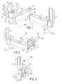
- Fig. 1 shows a device 1 according to the invention, which comprises a mounting bracket 2, which can be mounted on a wall, an arm 3, which is pivotally connected to the mounting bracket 2 about a pivot axis 2', an arm 5, which pivotally connected to the pivoting arm 3 about a pivot axis 4, and a support 7, which is pivotally connected to the arm 5 about a pivot axis 6.
- a connecting element 8 is detachably connected to the support 7.
- the mounting bracket 2 comprises a bushing 9, which is rigidly connected thereto, and a pin 10, which extends in upward direction from said bushing.
- a bushing 11 attached to one end of the arm 3 is supported on the pin 10, being pivotable about the pivot axis 2'.
- Positioned between the bushing 11 that is connected to the arm and the bushing 9 that is connected to the mounting bracket 2 is an 0-ring 12, whose external diameter is larger than the external diameter of the bushing 9, 11.
- the 0-ring 12 is preferably made of a relatively soft plastic material.
- the arm 3 is provided with a bushing 13 at an end remote from the bushing 11, and with a pin 14 extending in upward direction therefrom.
- a bushing 15 is supported on the pin 14, being pivotable about the axis 4, which bushing 15 is fixed to one end of the arm 5.
- Positioned between the bushings 13, 15 is an 0-ring 16, whose external diameter is larger than the external diameter of the bushings 13, 15.
- the arm 5 is provided with a bushing 17 at an end remote from the bushing 15, and with a pin 18 extending in upward direction therefrom.
- the support 7 is supported on the pin 18, being pivotable about the axis 6 thereof.
- Positioned between the support 7 and the bushing 17 is an 0-ring 19, whose external diameter is larger than the external diameter of the bushing 17.
- the 0-ring 19 extends beyond the support 7 over a relatively large part thereof.
- the arm 3 is identical to the arm 5, and the number of interconnected arms can be increased in a simple manner.
- the support 7 is provided with a U-shaped recess, which is bounded by two L-shaped legs 20, 21 positioned on either side of the recess.
- the connecting element 8 is detachably secured in the recess bounded by the L-shaped legs 20, 21.
- the connecting element 8 will be explained in more detail with reference to Figs. 4A, 4B , 5A and 5B .
- Fig. 2 shows a second embodiment of a device 22 according to the invention, which largely corresponds to the embodiment that is shown in Fig. 1 , except that the device 22 only comprises a single arm 3, with the support 7 being pivot-mounted in the bushing 13 by means of the pin 14.
- Fig. 3 shows a third embodiment of a device 23 according to the invention, in which the support 7 is pivot-mounted in the bushing 9 of the mounting bracket 2 by means of the pin 18.
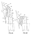
- Figs. 4A and 4B are side elevations of a part of the device that is shown in Fig. 1 , in which the connecting element is shown in a position in which it is disconnected from the support 7 and in a position in which it is connected thereto, respectively.
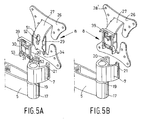
- Figs. 5A and 5B are perspective views of a part of the device of Fig. 1 , in which the connecting element is shown in partially disassembled condition and in assembled condition, respectively.
- the connecting element 8 comprises a first part 25, which is provided with a plate member 26 to be fixed to a component and with an arcuate guide 27 to be connected to the plate member 26.
- the first part 25 is made in one piece, for example by means of metal deforming techniques.
- the plate member 26 is provided with a number of mounting holes 28 (see Fig. 1 ) for fixing a component to the plate member 26, for example by means of bolts extending through the holes 28.
- the connecting element 8 furthermore comprises a second part 28.
- the second part 28 comprises two sections 29, 30 of plastic material positioned opposite each other, which are connected by means of a central pin 31.
- Positioned between the parts 29, 30 is an arcuate recess 32, with the curvature of the recess 32 and the spacing between the sections 29, 30 corresponding to the curvature and the thickness, respectively, of the arcuate guide 27.
- the arcuate guide 27 is positioned in the arcuate recess 32 bounded by the sections 29, 30.
- the accurate guide 27 is provided with a slot 51 ( Fig. 5A ) extending along the curvature of the arcuate guide 27 through which slot 51 the central pin 31 extends.
- the second part 28 furthermore comprises a lip 36 of plastic material.
- Said lip 36 comprises two parts 38 and 39 which are hinged together by means of a relatively thin plastic hinge member 37.
- the part 38 is provided with a projection 40 on a side remote from the hinged transition 37 which, in the position of the connecting element 8 that is shown in Fig. 4A , is in engagement with a recess 52 ( Fig. 5A ) present in the arcuate guide 27 of the first part 25.
- a user who wishes to mount a component, such as a flat screen, on a wall, for example, will proceed as follows.
- the user will fix the mounting bracket 2 to the wall, using suitable means of attachment.
- a bushing 11 is fitted over the pin 10 or the support 7 is directly positioned over the pin 10, depending on the number of arms 3, 5 that are needed.
- the support 7 is fixed to the end of the last arm. This may have been done at the works already.
- the plate member 26 is fixed to the component, using means of attachment such as bolts, at a desired location where sufficient support for the component is available, so that damage to the component is prevented.
- the flat screen is preferably laid on a flat supporting surface, such as a table, after which the plate member 26 is connected to the rear side of the flat screen.
- the user lifts up the component with the connecting element that is fixed thereto and moves the assembly to the position that is shown in Fig. 4A , in which the second part 28 of the connecting element 8 is positioned above the recess in the support 7 that is bounded by the L-shaped legs 20, 21.
- the connecting element 8 is moved in the direction indicated by the arrow P2, during which movement the second part 28 as well as the arcuate guide 27 present therein are moved into the recess bounded by the L-shaped legs 20, 21.
- the projections 34 on the arcuate guide act as guides upon insertion of the connecting element 8 into the support 7.
- the part 39 of the lip 36 of plastic material is thus moved into abutment with an upper side of the support 7, thus preventing the connecting element 8 from moving any further in the direction indicated by the arrow P2.
- a projection 41 which is present on a side of the part 38 remote from the projection 40, comes into contact with an upper edge of the support 7, as a result of which the part 38 is tilted about the hinge member 37 in the direction indicated by the arrow P1, as a result of which the engagement between the cam 40 and the arcuate guide is released.
- the accurate guide 27 can subsequently be freely tilted in the direction indicated by the arrow P1 and in the opposite direction.
- the second part 30 is provided with two barb-shaped elements 53 on a side remote from the part 39 of a lip 36 of plastic material, which elements engage a lower edge of the support 7.
- a solid connection between the connecting element 8 and the support is effected, in which the barb-shaped elements 53 prevent accidental movement of the connecting element 8 out of the support 7 in a simple manner.
- the dimensioning of the arcuate guide and the arcuate recess 32 is such that the arcuate guide 27 abuts against the section 29 at the upper side and against the section 30 at the bottom side under the influence of the weight of the connecting element 8 and the component that is connected thereto.
- the frictional forces that occur provide sufficient resistance to prevent the connecting element 8 and the component that is connected thereto from tilting any further in the direction indicated by the arrow P1. Only when a user takes hold of the component and tilts it in the direction indicated by the arrow P1 or in the opposite direction will a tilting movement actually take place.
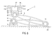
- Fig. 6 is a top plan view of the device 1 that is shown in Fig. 1 , in which the arms 3, 5 are shown to have been moved to a position in which they are disposed one above the other.
- the component that is connected to the connecting element is positioned relatively close to a wall 40.
- the arm 5 can be moved to a position even closer to the wall 40, in which position the pins 10 and 18 are in line, as it were.
- the relatively soft 0-ring 13 abuts against the wall 40, as a result of which damage to the wall 40 and/or the arms 3, 5 is prevented in a simple manner and only a relatively quiet sound is heard upon impact against the wall.
Landscapes
- Engineering & Computer Science (AREA)
- General Engineering & Computer Science (AREA)
- Mechanical Engineering (AREA)
- Pivots And Pivotal Connections (AREA)
- Devices For Indicating Variable Information By Combining Individual Elements (AREA)
- Branching, Merging, And Special Transfer Between Conveyors (AREA)
- Adornments (AREA)
- Control And Other Processes For Unpacking Of Materials (AREA)
- Electrical Discharge Machining, Electrochemical Machining, And Combined Machining (AREA)
Claims (8)
- Vorrichtung (1), die dazu geeignet ist, eine Komponente zu halten, wobei die Vorrichtung eine Halterung (7) aufweist, die mit mindestens einer Ausnehmung versehen ist, in der ein mit der Komponente verbindbares Verbindungselement (8) lösbar angebracht werden kann, wobei- das Verbindungselement (8) einen ersten Teil (25) mit einem Plattenelement (26), das lösbar mit der Komponente verbindbar ist, und mit einer bogenförmigen Führung (27) aufweist, die mit dem Plattenelement (26) verbunden ist,- das Verbindungselement (8) ferner einen lösbar mit der Halterung (7) zu verbindenden zweiten Teil (28) aufweist, wobei der zweite Teil (28) zwei Abschnitte (29, 30) und eine bogenförmige Ausnehmung (32) zwischen den beiden Abschnitten (29, 30) aufweist, in welcher die bogenförmige Führung (27) vorhanden ist,- die bogenförmige Führung (27) unter der Einwirkung des Gewichts des Verbindungselements (8) und der damit verbindbaren Komponente auf einer Seite an einem der Abschnitte (29) anliegt und auf der anderen Seite am anderen Abschnitt (30) anliegt,- zwischen der bogenförmigen Führung (27) und den Abschnitten (29, 30) auftretende Reibungskräfte einen ausreichenden Widerstand bereitstellen, um zu verhindern, dass das Verbindungselement (8) und die damit verbindbare Komponente kippen, dadurch gekennzeichnet, dass- die Komponente ein Flachbildschirm ist, mit dessen Rückseite das Plattenelement (26) verbunden werden kann,- die Vorrichtung (1) mit einer Wand (40) verbunden werden kann, wodurch sie, wenn der Flachbildschirm nicht verwendet wird, in einer Position angeordnet werden kann, in der sich der Flachbildschirm und das Plattenelement (26) im Wesentlichen parallel zur Wand (40) erstrecken,- das Verbindungselement (8) zusammen mit der Halterung (7) um eine sich senkrecht erstreckende Achse (6) geschwenkt werden kann, während der erste Teil des Verbindungselements (8) bezüglich der Halterung (7) um eine sich waagerecht erstreckende Achse (33) geneigt werden kann,- wobei sich in dieser Stellung die waagerecht und die senkrecht ersteckende Achse (6, 33) parallel zum Plattenelement erstrecken,- wodurch der erste Teil (25) mittels der bogenförmigen Führung (27) manuell gegen die Reibungskräfte bezüglich des zweiten Teils (28) um die sich waagerecht erstreckende Achse (33) geneigt werden kann.
- Vorrichtung (1) nach Anspruch 1, dadurch gekennzeichnet, dass das Verbindungselement (8) verschiebbar in der Ausnehmung der Halterung (7) angebracht sein kann.
- Vorrichtung (1) nach einem der vorhergehenden Ansprüche, dadurch gekennzeichnet, dass die bogenförmige Führung (27) in der bogenförmigen Ausnehmung (32) festgelegt sein kann.
- Vorrichtung (1) nach Anspruch 3, dadurch gekennzeichnet, dass das Verbindungselement (8) mit einer Lippe versehen ist, die unter Federkraft in die bogenförmige Führung (27) eingreift, wobei die Lippe bei der Befestigung des Verbindungselements (8) an der Halterung (7) außer Eingriff mit der bogenförmigen Führung bewegt wird.
- Vorrichtung (1) nach einem der vorhergehenden Ansprüche, dadurch gekennzeichnet, dass die Vorrichtung einen an einer Wand anzubringenden Befestigungsträger aufweist, mit dem die Halterung schwenkbar verbunden ist.
- Vorrichtung (1) nach Anspruch 5, dadurch gekennzeichnet, dass mindestens ein Arm zwischen dem Befestigungsträger und der Halterung (7) angeordnet ist, wobei der Arm mit einem Ende schwenkbar mit dem Befestigungsträger und mit dem anderen Ende schwenkbar mit der Halterung (7) verbunden ist.
- Vorrichtung (1) nach einem der vorhergehenden Ansprüche 5 oder 6, dadurch gekennzeichnet, dass zwischen dem Befestigungsträger, dem Arm/den Armen und/oder der Halterung (7), die zueinander schwenken können, ein O-Ring (13) vorhanden ist, wobei der O-Ring (13) einen Außendurchmesser besitzt, der größer ist als der des Befestigungsträgers, des Arms/der Arme und/oder der Halterung, die auf beiden Seiten des O-Rings (13) vorhanden sind.
- Vorrichtung (1) nach einem der vorhergehenden Ansprüche, dadurch gekennzeichnet, dass die Halterung (7) mit einer U-förmigen Ausnehmung versehen ist, wobei die Schenkel der U-förmigen Ausnehmung (32) sich zumindest teilweise um die bogenförmige Ausnehmung (32) und die bogenförmige Führung (27) erstrecken, wenn das Verbindungselement (8) mit der Halterung (7) verbunden ist.
Applications Claiming Priority (2)
| Application Number | Priority Date | Filing Date | Title |
|---|---|---|---|
| NL1023051 | 2003-03-31 | ||
| NL1023051A NL1023051C1 (nl) | 2003-03-31 | 2003-03-31 | Inrichting geschikt voor het ondersteunen van een component. |
Publications (3)
| Publication Number | Publication Date |
|---|---|
| EP1471300A2 EP1471300A2 (de) | 2004-10-27 |
| EP1471300A3 EP1471300A3 (de) | 2005-04-13 |
| EP1471300B1 true EP1471300B1 (de) | 2009-07-01 |
Family
ID=32960318
Family Applications (1)
| Application Number | Title | Priority Date | Filing Date |
|---|---|---|---|
| EP04075928A Expired - Lifetime EP1471300B1 (de) | 2003-03-31 | 2004-03-24 | Vorrichtung zum Tragen von einem Element |
Country Status (5)
| Country | Link |
|---|---|
| EP (1) | EP1471300B1 (de) |
| AT (1) | ATE435395T1 (de) |
| DE (1) | DE602004021742D1 (de) |
| ES (1) | ES2251892T1 (de) |
| NL (1) | NL1023051C1 (de) |
Cited By (2)
| Publication number | Priority date | Publication date | Assignee | Title |
|---|---|---|---|---|
| USD743969S1 (en) | 2013-10-16 | 2015-11-24 | Wirepath Home Systems, Llc | Single arm articulating mount for an electronic display |
| USD747724S1 (en) | 2013-12-20 | 2016-01-19 | Wirepath Home Systems, Llc | Dual arm articulating mount for an electronic display |
Families Citing this family (19)
| Publication number | Priority date | Publication date | Assignee | Title |
|---|---|---|---|---|
| USD688674S1 (en) | 1920-12-09 | 2013-08-27 | Colebrook Bosson Saunders (Products) Limited | Display support |
| USD645868S1 (en) | 2010-06-09 | 2011-09-27 | Colebrook Bosson Saunders (Products) Limited | Display support |
| NL1027626C2 (nl) | 2004-11-30 | 2006-05-31 | Vogel S Holding Bv | Inrichting geschikt voor het ondersteunen van een component. |
| DE202005007184U1 (de) * | 2005-05-04 | 2006-06-14 | Knott Gmbh | Verbindungssystem zur Befestigung von Zugholmen am Fahrgestell eines Kraftfahrzeuganhängers |
| US20070153459A1 (en) * | 2006-01-04 | 2007-07-05 | Jim Wohlford | Mounting system for flat panel electronic display |
| GB2438581A (en) * | 2006-05-31 | 2007-12-05 | Colebrook Bosson Saunders Prod | Adjustable support bracket for a flat-screen monitor |
| NL1032397C2 (nl) | 2006-08-31 | 2008-03-03 | Vogel S Holding Bv | Inrichting voorzien van een houder, een in de houder gelegen geleiding en een ten opzichte van de geleiding verplaatsbaar element. |
| US20100038508A1 (en) | 2006-10-06 | 2010-02-18 | Dirk Jan Stoelinga | Support Arm |
| NL2000262C2 (nl) * | 2006-10-06 | 2008-04-08 | S & B Systems B V | Draagarm. |
| US7658355B2 (en) | 2007-02-20 | 2010-02-09 | S & B Systems B.V. | Support arm |
| GB2447623B8 (en) * | 2007-03-22 | 2018-01-03 | Colebrook Bosson & Saunders (Products) Ltd | Flat-screen monitor support |
| KR20080105402A (ko) * | 2007-05-30 | 2008-12-04 | 삼성전자주식회사 | 지지장치 및 이를 갖는 디스플레이장치 |
| GB2450380B (en) * | 2007-06-22 | 2009-10-07 | Path Distrib Ltd | Improvements in hubs for wall mounting systems |
| CA132481S (en) | 2009-04-10 | 2011-03-14 | S & B Systems B V | Support arm for computer monitor |
| US9316346B2 (en) | 2010-06-09 | 2016-04-19 | Colebrook Bosson Saunders (Products) Limited | Support system |
| GB2481047A (en) * | 2010-06-09 | 2011-12-14 | Colebrook Bosson & Saunders Products Ltd | A mounting system for pivotally mounting a flat screen display |
| US9074721B2 (en) | 2010-06-09 | 2015-07-07 | Alex Lau | Support system |
| USD684982S1 (en) | 2010-08-11 | 2013-06-25 | Colebrook Bosson Saunders (Products) Limited | Display support with indicator window |
| GB201712757D0 (en) * | 2017-08-09 | 2017-09-20 | Timeguard Ltd | Variable-angle brackets |
Family Cites Families (7)
| Publication number | Priority date | Publication date | Assignee | Title |
|---|---|---|---|---|
| US4516751A (en) * | 1982-09-17 | 1985-05-14 | Charles Westbrook | Wall bracket system |
| EP0202446B1 (de) * | 1985-04-15 | 1990-12-27 | Siemens Aktiengesellschaft | Neigevorrichtung für Sichtgeräte |
| US5833183A (en) * | 1997-03-18 | 1998-11-10 | Compal Electronics, Inc. | Adjustable support structure for liquid crystal display |
| KR100255765B1 (ko) * | 1997-07-09 | 2000-05-01 | 구자홍 | 영상표시기기의 전후 조절 받침대 구조 |
| DE29905420U1 (de) * | 1999-03-29 | 1999-07-08 | Schwering | Halterung für ein Gerät |
| GB2360894B (en) * | 2000-03-30 | 2004-11-10 | Peter Thomas Bosson | Display device support system |
| US6367756B1 (en) * | 2000-07-07 | 2002-04-09 | James Wang | Adjustable device support and anchor means arrangement |
-
2003
- 2003-03-31 NL NL1023051A patent/NL1023051C1/nl not_active IP Right Cessation
-
2004
- 2004-03-24 ES ES04075928T patent/ES2251892T1/es active Pending
- 2004-03-24 AT AT04075928T patent/ATE435395T1/de not_active IP Right Cessation
- 2004-03-24 DE DE602004021742T patent/DE602004021742D1/de not_active Expired - Lifetime
- 2004-03-24 EP EP04075928A patent/EP1471300B1/de not_active Expired - Lifetime
Cited By (3)
| Publication number | Priority date | Publication date | Assignee | Title |
|---|---|---|---|---|
| USD743969S1 (en) | 2013-10-16 | 2015-11-24 | Wirepath Home Systems, Llc | Single arm articulating mount for an electronic display |
| USD747724S1 (en) | 2013-12-20 | 2016-01-19 | Wirepath Home Systems, Llc | Dual arm articulating mount for an electronic display |
| USD788783S1 (en) | 2013-12-20 | 2017-06-06 | Wirepath Home Systems, Llc | Dual arm articulating mount for an electronic display |
Also Published As
| Publication number | Publication date |
|---|---|
| NL1023051C1 (nl) | 2004-10-01 |
| EP1471300A3 (de) | 2005-04-13 |
| DE602004021742D1 (de) | 2009-08-13 |
| EP1471300A2 (de) | 2004-10-27 |
| ATE435395T1 (de) | 2009-07-15 |
| ES2251892T1 (es) | 2006-05-16 |
Similar Documents
| Publication | Publication Date | Title |
|---|---|---|
| EP1471300B1 (de) | Vorrichtung zum Tragen von einem Element | |
| US9316346B2 (en) | Support system | |
| US8891249B2 (en) | Display mount with adjustable position tilt axis | |
| EP1662193B1 (de) | Vorrichtung zum Tragen von einem Element | |
| US6752363B2 (en) | Device for tiltable mounting of a display screen on a wall | |
| US7669812B2 (en) | Stand for display device | |
| KR100534120B1 (ko) | 모니터장치 | |
| US7177144B2 (en) | Tilting apparatus of monitor | |
| CA1179723A (en) | Display station tilt mechanism | |
| US11828406B2 (en) | High load display support system | |
| WO2007137905A1 (en) | Flat-screen monitor support | |
| WO2008050549A2 (en) | Desktop phone with stand adjustable for height | |
| US20210364122A1 (en) | Height adjustable monitor arm mounting assembly | |
| US8033516B2 (en) | Device suitable for tiltably mounting a display screen on a wall, as well as such a method | |
| EP0238785A2 (de) | Neigbarer Monitor | |
| CA2413828A1 (en) | Adjustable arm support | |
| JP4371419B2 (ja) | 壁掛け取り付け台 | |
| KR20170098551A (ko) | 모니터용 메모보드 | |
| EP0862014A1 (de) | Tragvorrichtung | |
| KR100671298B1 (ko) | 디스플레이 설치장치 | |
| EP3795881B1 (de) | Installationsscharnier und installationsverfahren | |
| US4405046A (en) | Tray attachment for a chair | |
| WO2006106497A1 (en) | Positioning mechanism and mount apparatus including the same | |
| CN112996333A (zh) | 理线总成 | |
| GB2446222A (en) | A computer camera periscope |
Legal Events
| Date | Code | Title | Description |
|---|---|---|---|
| PUAI | Public reference made under article 153(3) epc to a published international application that has entered the european phase |
Free format text: ORIGINAL CODE: 0009012 |
|
| AK | Designated contracting states |
Kind code of ref document: A2 Designated state(s): AT BE BG CH CY CZ DE DK EE ES FI FR GB GR HU IE IT LI LU MC NL PL PT RO SE SI SK TR |
|
| AX | Request for extension of the european patent |
Extension state: AL HR LT LV MK |
|
| PUAL | Search report despatched |
Free format text: ORIGINAL CODE: 0009013 |
|
| AK | Designated contracting states |
Kind code of ref document: A3 Designated state(s): AT BE BG CH CY CZ DE DK EE ES FI FR GB GR HU IE IT LI LU MC NL PL PT RO SE SI SK TR |
|
| AX | Request for extension of the european patent |
Extension state: AL HR LT LV MK |
|
| RIC1 | Information provided on ipc code assigned before grant |
Ipc: 7F 16M 11/04 B Ipc: 7F 16M 11/10 A Ipc: 7F 16M 11/12 B |
|
| 17P | Request for examination filed |
Effective date: 20051004 |
|
| AKX | Designation fees paid |
Designated state(s): AT BE BG CH CY CZ DE DK EE ES FI FR GB GR HU IE IT LI LU MC NL PL PT RO SE SI SK TR |
|
| 17Q | First examination report despatched |
Effective date: 20061002 |
|
| GRAP | Despatch of communication of intention to grant a patent |
Free format text: ORIGINAL CODE: EPIDOSNIGR1 |
|
| GRAS | Grant fee paid |
Free format text: ORIGINAL CODE: EPIDOSNIGR3 |
|
| GRAA | (expected) grant |
Free format text: ORIGINAL CODE: 0009210 |
|
| AK | Designated contracting states |
Kind code of ref document: B1 Designated state(s): AT BE BG CH CY CZ DE DK EE ES FI FR GB GR HU IE IT LI LU MC NL PL PT RO SE SI SK TR |
|
| REG | Reference to a national code |
Ref country code: GB Ref legal event code: FG4D |
|
| REG | Reference to a national code |
Ref country code: CH Ref legal event code: EP |
|
| REG | Reference to a national code |
Ref country code: IE Ref legal event code: FG4D |
|
| REF | Corresponds to: |
Ref document number: 602004021742 Country of ref document: DE Date of ref document: 20090813 Kind code of ref document: P |
|
| PG25 | Lapsed in a contracting state [announced via postgrant information from national office to epo] |
Ref country code: SI Free format text: LAPSE BECAUSE OF FAILURE TO SUBMIT A TRANSLATION OF THE DESCRIPTION OR TO PAY THE FEE WITHIN THE PRESCRIBED TIME-LIMIT Effective date: 20090701 |
|
| PG25 | Lapsed in a contracting state [announced via postgrant information from national office to epo] |
Ref country code: AT Free format text: LAPSE BECAUSE OF FAILURE TO SUBMIT A TRANSLATION OF THE DESCRIPTION OR TO PAY THE FEE WITHIN THE PRESCRIBED TIME-LIMIT Effective date: 20090701 Ref country code: SE Free format text: LAPSE BECAUSE OF FAILURE TO SUBMIT A TRANSLATION OF THE DESCRIPTION OR TO PAY THE FEE WITHIN THE PRESCRIBED TIME-LIMIT Effective date: 20090701 Ref country code: FI Free format text: LAPSE BECAUSE OF FAILURE TO SUBMIT A TRANSLATION OF THE DESCRIPTION OR TO PAY THE FEE WITHIN THE PRESCRIBED TIME-LIMIT Effective date: 20090701 Ref country code: ES Free format text: LAPSE BECAUSE OF FAILURE TO SUBMIT A TRANSLATION OF THE DESCRIPTION OR TO PAY THE FEE WITHIN THE PRESCRIBED TIME-LIMIT Effective date: 20091012 Ref country code: EE Free format text: LAPSE BECAUSE OF FAILURE TO SUBMIT A TRANSLATION OF THE DESCRIPTION OR TO PAY THE FEE WITHIN THE PRESCRIBED TIME-LIMIT Effective date: 20090701 |
|
| PG25 | Lapsed in a contracting state [announced via postgrant information from national office to epo] |
Ref country code: PL Free format text: LAPSE BECAUSE OF FAILURE TO SUBMIT A TRANSLATION OF THE DESCRIPTION OR TO PAY THE FEE WITHIN THE PRESCRIBED TIME-LIMIT Effective date: 20090701 |
|
| PG25 | Lapsed in a contracting state [announced via postgrant information from national office to epo] |
Ref country code: BG Free format text: LAPSE BECAUSE OF FAILURE TO SUBMIT A TRANSLATION OF THE DESCRIPTION OR TO PAY THE FEE WITHIN THE PRESCRIBED TIME-LIMIT Effective date: 20091001 Ref country code: PT Free format text: LAPSE BECAUSE OF FAILURE TO SUBMIT A TRANSLATION OF THE DESCRIPTION OR TO PAY THE FEE WITHIN THE PRESCRIBED TIME-LIMIT Effective date: 20091102 |
|
| PG25 | Lapsed in a contracting state [announced via postgrant information from national office to epo] |
Ref country code: DK Free format text: LAPSE BECAUSE OF FAILURE TO SUBMIT A TRANSLATION OF THE DESCRIPTION OR TO PAY THE FEE WITHIN THE PRESCRIBED TIME-LIMIT Effective date: 20090701 Ref country code: CZ Free format text: LAPSE BECAUSE OF FAILURE TO SUBMIT A TRANSLATION OF THE DESCRIPTION OR TO PAY THE FEE WITHIN THE PRESCRIBED TIME-LIMIT Effective date: 20090701 Ref country code: RO Free format text: LAPSE BECAUSE OF FAILURE TO SUBMIT A TRANSLATION OF THE DESCRIPTION OR TO PAY THE FEE WITHIN THE PRESCRIBED TIME-LIMIT Effective date: 20090701 |
|
| PLBE | No opposition filed within time limit |
Free format text: ORIGINAL CODE: 0009261 |
|
| STAA | Information on the status of an ep patent application or granted ep patent |
Free format text: STATUS: NO OPPOSITION FILED WITHIN TIME LIMIT |
|
| PG25 | Lapsed in a contracting state [announced via postgrant information from national office to epo] |
Ref country code: SK Free format text: LAPSE BECAUSE OF FAILURE TO SUBMIT A TRANSLATION OF THE DESCRIPTION OR TO PAY THE FEE WITHIN THE PRESCRIBED TIME-LIMIT Effective date: 20090701 Ref country code: BE Free format text: LAPSE BECAUSE OF FAILURE TO SUBMIT A TRANSLATION OF THE DESCRIPTION OR TO PAY THE FEE WITHIN THE PRESCRIBED TIME-LIMIT Effective date: 20090701 |
|
| 26N | No opposition filed |
Effective date: 20100406 |
|
| PG25 | Lapsed in a contracting state [announced via postgrant information from national office to epo] |
Ref country code: GR Free format text: LAPSE BECAUSE OF FAILURE TO SUBMIT A TRANSLATION OF THE DESCRIPTION OR TO PAY THE FEE WITHIN THE PRESCRIBED TIME-LIMIT Effective date: 20091002 Ref country code: MC Free format text: LAPSE BECAUSE OF NON-PAYMENT OF DUE FEES Effective date: 20100331 |
|
| REG | Reference to a national code |
Ref country code: CH Ref legal event code: PL |
|
| GBPC | Gb: european patent ceased through non-payment of renewal fee |
Effective date: 20100324 |
|
| REG | Reference to a national code |
Ref country code: FR Ref legal event code: ST Effective date: 20101130 |
|
| PG25 | Lapsed in a contracting state [announced via postgrant information from national office to epo] |
Ref country code: FR Free format text: LAPSE BECAUSE OF NON-PAYMENT OF DUE FEES Effective date: 20100331 Ref country code: IE Free format text: LAPSE BECAUSE OF NON-PAYMENT OF DUE FEES Effective date: 20100324 |
|
| PG25 | Lapsed in a contracting state [announced via postgrant information from national office to epo] |
Ref country code: LI Free format text: LAPSE BECAUSE OF NON-PAYMENT OF DUE FEES Effective date: 20100331 Ref country code: CH Free format text: LAPSE BECAUSE OF NON-PAYMENT OF DUE FEES Effective date: 20100331 |
|
| PG25 | Lapsed in a contracting state [announced via postgrant information from national office to epo] |
Ref country code: IT Free format text: LAPSE BECAUSE OF FAILURE TO SUBMIT A TRANSLATION OF THE DESCRIPTION OR TO PAY THE FEE WITHIN THE PRESCRIBED TIME-LIMIT Effective date: 20090701 Ref country code: GB Free format text: LAPSE BECAUSE OF NON-PAYMENT OF DUE FEES Effective date: 20100324 |
|
| PG25 | Lapsed in a contracting state [announced via postgrant information from national office to epo] |
Ref country code: CY Free format text: LAPSE BECAUSE OF FAILURE TO SUBMIT A TRANSLATION OF THE DESCRIPTION OR TO PAY THE FEE WITHIN THE PRESCRIBED TIME-LIMIT Effective date: 20090701 |
|
| PG25 | Lapsed in a contracting state [announced via postgrant information from national office to epo] |
Ref country code: LU Free format text: LAPSE BECAUSE OF NON-PAYMENT OF DUE FEES Effective date: 20100324 Ref country code: HU Free format text: LAPSE BECAUSE OF FAILURE TO SUBMIT A TRANSLATION OF THE DESCRIPTION OR TO PAY THE FEE WITHIN THE PRESCRIBED TIME-LIMIT Effective date: 20100102 |
|
| PG25 | Lapsed in a contracting state [announced via postgrant information from national office to epo] |
Ref country code: TR Free format text: LAPSE BECAUSE OF FAILURE TO SUBMIT A TRANSLATION OF THE DESCRIPTION OR TO PAY THE FEE WITHIN THE PRESCRIBED TIME-LIMIT Effective date: 20090701 |
|
| REG | Reference to a national code |
Ref country code: NL Ref legal event code: PD Owner name: VOGEL'S IP B.V.; NL Free format text: DETAILS ASSIGNMENT: CHANGE OF OWNER(S), ASSIGNMENT; FORMER OWNER NAME: VOGEL'S HOLDING B.V. Effective date: 20220516 |
|
| REG | Reference to a national code |
Ref country code: DE Ref legal event code: R081 Ref document number: 602004021742 Country of ref document: DE Owner name: VOGEL'S IP B.V., NL Free format text: FORMER OWNER: VOGEL'S HOLDING B.V., 5628 EINDHOVEN, NL Ref country code: DE Ref legal event code: R082 Ref document number: 602004021742 Country of ref document: DE Representative=s name: DENNEMEYER & ASSOCIATES S.A., DE |
|
| PGFP | Annual fee paid to national office [announced via postgrant information from national office to epo] |
Ref country code: DE Payment date: 20230321 Year of fee payment: 20 |
|
| PGFP | Annual fee paid to national office [announced via postgrant information from national office to epo] |
Ref country code: NL Payment date: 20230321 Year of fee payment: 20 |
|
| P01 | Opt-out of the competence of the unified patent court (upc) registered |
Effective date: 20230527 |
|
| REG | Reference to a national code |
Ref country code: DE Ref legal event code: R071 Ref document number: 602004021742 Country of ref document: DE |
|
| REG | Reference to a national code |
Ref country code: NL Ref legal event code: MK Effective date: 20240323 |