EP1471242A1 - Self-diagnosis display unit - Google Patents
Self-diagnosis display unit Download PDFInfo
- Publication number
- EP1471242A1 EP1471242A1 EP03705012A EP03705012A EP1471242A1 EP 1471242 A1 EP1471242 A1 EP 1471242A1 EP 03705012 A EP03705012 A EP 03705012A EP 03705012 A EP03705012 A EP 03705012A EP 1471242 A1 EP1471242 A1 EP 1471242A1
- Authority
- EP
- European Patent Office
- Prior art keywords
- startup
- self
- indication
- detected
- disablement
- Prior art date
- Legal status (The legal status is an assumption and is not a legal conclusion. Google has not performed a legal analysis and makes no representation as to the accuracy of the status listed.)
- Granted
Links
Images

Classifications
-
- F—MECHANICAL ENGINEERING; LIGHTING; HEATING; WEAPONS; BLASTING
- F02—COMBUSTION ENGINES; HOT-GAS OR COMBUSTION-PRODUCT ENGINE PLANTS
- F02D—CONTROLLING COMBUSTION ENGINES
- F02D41/00—Electrical control of supply of combustible mixture or its constituents
- F02D41/02—Circuit arrangements for generating control signals
- F02D41/04—Introducing corrections for particular operating conditions
- F02D41/06—Introducing corrections for particular operating conditions for engine starting or warming up
- F02D41/062—Introducing corrections for particular operating conditions for engine starting or warming up for starting
-
- F—MECHANICAL ENGINEERING; LIGHTING; HEATING; WEAPONS; BLASTING
- F02—COMBUSTION ENGINES; HOT-GAS OR COMBUSTION-PRODUCT ENGINE PLANTS
- F02D—CONTROLLING COMBUSTION ENGINES
- F02D41/00—Electrical control of supply of combustible mixture or its constituents
- F02D41/22—Safety or indicating devices for abnormal conditions
-
- F—MECHANICAL ENGINEERING; LIGHTING; HEATING; WEAPONS; BLASTING
- F02—COMBUSTION ENGINES; HOT-GAS OR COMBUSTION-PRODUCT ENGINE PLANTS
- F02N—STARTING OF COMBUSTION ENGINES; STARTING AIDS FOR SUCH ENGINES, NOT OTHERWISE PROVIDED FOR
- F02N15/00—Other power-operated starting apparatus; Component parts, details, or accessories, not provided for in, or of interest apart from groups F02N5/00 - F02N13/00
- F02N15/10—Safety devices not otherwise provided for
-
- F—MECHANICAL ENGINEERING; LIGHTING; HEATING; WEAPONS; BLASTING
- F02—COMBUSTION ENGINES; HOT-GAS OR COMBUSTION-PRODUCT ENGINE PLANTS
- F02D—CONTROLLING COMBUSTION ENGINES
- F02D41/00—Electrical control of supply of combustible mixture or its constituents
- F02D41/22—Safety or indicating devices for abnormal conditions
- F02D2041/228—Warning displays
-
- Y—GENERAL TAGGING OF NEW TECHNOLOGICAL DEVELOPMENTS; GENERAL TAGGING OF CROSS-SECTIONAL TECHNOLOGIES SPANNING OVER SEVERAL SECTIONS OF THE IPC; TECHNICAL SUBJECTS COVERED BY FORMER USPC CROSS-REFERENCE ART COLLECTIONS [XRACs] AND DIGESTS
- Y02—TECHNOLOGIES OR APPLICATIONS FOR MITIGATION OR ADAPTATION AGAINST CLIMATE CHANGE
- Y02T—CLIMATE CHANGE MITIGATION TECHNOLOGIES RELATED TO TRANSPORTATION
- Y02T10/00—Road transport of goods or passengers
- Y02T10/10—Internal combustion engine [ICE] based vehicles
- Y02T10/40—Engine management systems
Definitions
- the present invention relates to a self diagnosis indication system (a diagnosis indication system) such as provided on automobiles and/or motorcycles.
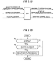
- Fig. 2 The configuration and operation flow of a conventional self-diagnosis indication system is shown in Fig. 2.
- detection signals from respective types of sensors for detecting an operating condition of an engine, an on/off signal from a starter switch and a crank pulse signal for detecting the rotation of a crankshaft to thereby calculate an engine rotational speed and a crank angle are inputted into an ECU (engine control unit).
- the ECU performs operation controls on such as ignition timing and fuel inj ection based on predetermined programs and maps according to these signals and outputs an abnormality indication signal to illuminate an indication lamp so as to indicate the presence of an abnormal condition when any abnormality is detected which results from disconnection and short circuit.
- a startup disablement indication is implemented.
- step S1 whether or not the abnormality was detected by a self-diagnosis is determined (step S1), and whether or not the abnormality was detected at the time of startup is determined by judging whether or not the starter switch was switched on when the abnormal condition occurred (step S2), and in the event that it was at the time of startup, then a startup disablement indication is implemented (step S3).
- the present invention was intended to deal with the related art and an object thereof is to provide a self-diagnosis indication system for performing a startup disablement indication when an abnormal condition is self-detected at the time of startup without using on/off signals from a starter switch.
- a self-diagnosis indication system for outputting an operation control signal from an ECU by allowing signals from respective types of sensors for detecting an operating condition and a crank pulse signal for detecting a rotation of a crankshaft to enter the ECU and outputting a startup disablement indication signal in a state that an abnormal condition is self-detected at the time of startup, the self-diagnosis indication system being characterized in that a startup disablement indication signal is outputted when a crank pulse signal is inputted in the state that an abnormal condition is self-detected.
- a startup disablement indication signal can be outputted so as to indicate that a startup is not possible.
- the self-diagnosis indication system has an abnormality indicating means for indicating the abnormal condition so self-detected, whereby a startup disablement condition is indicated by changing indication modes of the abnormality indicating means by the startup disablement indication signal.
- an abnormal condition is indicated by illuminating, for example, an indication lamp when the abnormal condition is self-detected, and when a startup is attempted in this abnormal condition, the indication modes of the indication lamp are changed, for example, to cause the indication lamp to flash so as to indicate a startup disablement condition.
- Fig. 1 shows explanatory diagrams depicting the configuration and operation flow of an embodiment of the present invention .
- detection signals from respective types of sensors for example, an intake air pressure sensor, a throttle position sensor, a coolant temperature sensor, an atmospheric pressure sensor, and an intake air temperature sensor
- a crank pulse signal for detecting the rotation of a crankshaft to thereby calculate an engine rotational speed and a crank angle
- the ECU performs operation controls on such as ignition timing and fuel injection based on predetermined programs and maps according to these signals and outputs an abnormality indication signal to illuminate an indication lamp so as to indicate the presence of an abnormal condition when any abnormality is detected which results from disconnection and short circuit.
- a startup disablement indication is implemented.
- step T1 firstly, whether or not the abnormality was detected by a self-diagnosis is determined (step T1). This is a step for determining whether or not a certain failure such as disconnection or short circuit of the sensors has been detected. If an abnormality is determined in this step T1, an abnormality indication is implemented by illuminating, for example, a red lamp.
- step T2 whether or not a crank pulse signal exists, that is, an engine is rotating when the abnormality is occurring (when YES in T1) is determined (step T2). Thus, whether or not the engine has been operated to be put in a startup condition is determined. If the engine is in the startup condition (when YES in T2), a startup disablement indication is implemented (step T3).
- This startup disablement indication can be, for example, a red lamp flashing indication by changing the indication modes of the red lamp.
- the user can be aware that the engine is in the operation disablement condition.
- a startup disablement indication signal can be outputted so as to indicate that a startup is not possible.
- a startup disablement indication can be implemented without using on/off signals of the starter switch but with a simple configuration using simple and inexpensive wiring and circuits.
Landscapes
- Engineering & Computer Science (AREA)
- Chemical & Material Sciences (AREA)
- Combustion & Propulsion (AREA)
- Mechanical Engineering (AREA)
- General Engineering & Computer Science (AREA)
- Combined Controls Of Internal Combustion Engines (AREA)
- Testing Of Engines (AREA)
Abstract
Description
Claims (2)
- A self-diagnosis indication system for outputting an operation control signal from an ECU by allowing signals from respective types of sensors for detecting an operating condition and a crank pulse signal for detecting a rotation of a crankshaft to enter the ECU and outputting a startup disablement indication signal in a state that an abnormal condition is self-detected at the time of startup, the self-diagnosis indication system being characterized in that;
a startup disablement indication signal is outputted when a crank pulse signal is inputted in the state that an abnormal condition is self-detected. - A self-diagnosis indication system as set forth in Claim 1, having abnormality indicating means for indicating the abnormal condition so self-detected, whereby a startup disablement condition is indicatedby changing indicationmodes of the abnormality indicating means by the startup disablement indication signal.
Applications Claiming Priority (3)
| Application Number | Priority Date | Filing Date | Title |
|---|---|---|---|
| JP2002019851 | 2002-01-29 | ||
| JP2002019851 | 2002-01-29 | ||
| PCT/JP2003/000504 WO2003064839A1 (en) | 2002-01-29 | 2003-01-22 | Self-diagnosis display unit |
Publications (3)
| Publication Number | Publication Date |
|---|---|
| EP1471242A1 true EP1471242A1 (en) | 2004-10-27 |
| EP1471242A4 EP1471242A4 (en) | 2009-09-09 |
| EP1471242B1 EP1471242B1 (en) | 2020-04-01 |
Family
ID=27654298
Family Applications (1)
| Application Number | Title | Priority Date | Filing Date |
|---|---|---|---|
| EP03705012.7A Expired - Lifetime EP1471242B1 (en) | 2002-01-29 | 2003-01-22 | Self-diagnosis display unit |
Country Status (8)
| Country | Link |
|---|---|
| US (1) | US7319926B2 (en) |
| EP (1) | EP1471242B1 (en) |
| JP (1) | JPWO2003064839A1 (en) |
| CN (1) | CN1304746C (en) |
| BR (1) | BR0307043A (en) |
| ES (1) | ES2792174T3 (en) |
| TW (1) | TW576889B (en) |
| WO (1) | WO2003064839A1 (en) |
Families Citing this family (9)
| Publication number | Priority date | Publication date | Assignee | Title |
|---|---|---|---|---|
| US20030158635A1 (en) * | 1999-07-30 | 2003-08-21 | Oshkosh Truck Corporation | Firefighting vehicle with network-assisted scene management |
| JP4867239B2 (en) * | 2005-09-05 | 2012-02-01 | カシオ計算機株式会社 | Information processing apparatus, self-diagnosis method and program |
| JP5144169B2 (en) * | 2007-08-17 | 2013-02-13 | 本田技研工業株式会社 | Cogeneration equipment |
| JP4990233B2 (en) * | 2008-06-25 | 2012-08-01 | 本田技研工業株式会社 | Electronic throttle control device |
| DE102009028955A1 (en) * | 2009-08-06 | 2011-02-10 | Robert Bosch Gmbh | Method and device for monitoring a device for switching a starter |
| DE102009028294A1 (en) * | 2009-08-06 | 2011-02-10 | Robert Bosch Gmbh | Device for starting an internal combustion engine |
| US8534082B2 (en) | 2010-07-20 | 2013-09-17 | Thermo King Corporation | Engine starter predictive maintenance system |
| CN107490129B (en) * | 2017-08-02 | 2020-10-20 | 青岛海尔空调电子有限公司 | A device control method and device |
| CN109253012A (en) * | 2018-10-15 | 2019-01-22 | 襄阳全系康动力机械有限责任公司 | A kind of comprehensive protective device for electric starting of engine and its application method |
Family Cites Families (21)
| Publication number | Priority date | Publication date | Assignee | Title |
|---|---|---|---|---|
| GB112540A (en) * | 1917-02-27 | 1918-01-17 | Arthur George Bloxam | A Safety Device to Prevent a Back Stroke while Starting an Internal Combustion Engine by a Hand Crank. |
| JPS55126841A (en) * | 1979-03-23 | 1980-10-01 | Nissan Motor Co Ltd | Diagnosing method of controller for motorcar |
| JPS59190478A (en) | 1983-04-12 | 1984-10-29 | Honda Motor Co Ltd | Abnormality detecting method of starter device in internal-combustion engine |
| US4561296A (en) * | 1984-10-17 | 1985-12-31 | Marelli Autronica S.P.A. | Diagnostic device for a system for controlling the stopping and restarting of a internal combustion engine for motor vehicles |
| JPH0735355B2 (en) | 1986-08-29 | 1995-04-19 | ダイセル化学工業株式会社 | Method for producing carbonate ester |
| JPS6357552U (en) * | 1986-10-01 | 1988-04-16 | ||
| US4787352A (en) * | 1987-08-06 | 1988-11-29 | Barber-Coleman Company | Engine control circuit including speed monitor and governor |
| CA2139073C (en) * | 1994-12-23 | 1999-04-20 | Normand Dery | Automotive opto-electric starter interlock |
| DE19547647A1 (en) * | 1995-12-20 | 1997-06-26 | Bosch Gmbh Robert | Method and device for monitoring a fuel metering system of an internal combustion engine |
| JP3166634B2 (en) * | 1996-11-07 | 2001-05-14 | 日産自動車株式会社 | Fault storage device for vehicle control unit |
| JPH10253505A (en) * | 1997-03-10 | 1998-09-25 | Honda Motor Co Ltd | Vehicle diagnostic method and device |
| GB2323631A (en) * | 1997-03-27 | 1998-09-30 | David Martin Keene | Diesel engine start inhibitor system |
| JP4241953B2 (en) * | 1998-01-19 | 2009-03-18 | 株式会社デンソー | Diagnostic equipment for vehicles |
| DE19836059A1 (en) * | 1998-08-10 | 2000-02-17 | Mannesmann Vdo Ag | Method and device for controlling a power adjustment device of a vehicle engine |
| JP3485026B2 (en) * | 1999-05-25 | 2004-01-13 | 三菱自動車工業株式会社 | Vehicle self-diagnosis device |
| JP3710337B2 (en) | 1999-08-26 | 2005-10-26 | 富士通テン株式会社 | Injector valve control method and apparatus |
| DE19957732B4 (en) * | 1999-12-01 | 2004-05-13 | Siemens Ag | Procedure for checking an operational safety-relevant component of a plant |
| US6553289B2 (en) * | 2000-04-28 | 2003-04-22 | Denso Corporation | Control apparatus having object-oriented self-diagnosis program |
| JP2002132533A (en) * | 2000-10-27 | 2002-05-10 | Denso Corp | Vehicle control device with self-diagnosis function and recording medium |
| JP4491967B2 (en) * | 2000-12-28 | 2010-06-30 | 株式会社デンソー | VEHICLE CONTROL DEVICE AND RECORDING MEDIUM HAVING SELF-DIAGNOSTIC FUNCTION |
| JP2004359189A (en) * | 2003-06-09 | 2004-12-24 | Kawasaki Heavy Ind Ltd | Self-diagnosis information processing method and self-diagnosis information processing device for personal watercraft |
-
2003
- 2003-01-22 BR BR0307043-3A patent/BR0307043A/en not_active IP Right Cessation
- 2003-01-22 ES ES03705012T patent/ES2792174T3/en not_active Expired - Lifetime
- 2003-01-22 EP EP03705012.7A patent/EP1471242B1/en not_active Expired - Lifetime
- 2003-01-22 US US10/501,800 patent/US7319926B2/en not_active Expired - Lifetime
- 2003-01-22 WO PCT/JP2003/000504 patent/WO2003064839A1/en not_active Ceased
- 2003-01-22 CN CNB038008203A patent/CN1304746C/en not_active Expired - Lifetime
- 2003-01-22 JP JP2003564414A patent/JPWO2003064839A1/en active Pending
- 2003-01-29 TW TW092101951A patent/TW576889B/en not_active IP Right Cessation
Also Published As
| Publication number | Publication date |
|---|---|
| US20050119808A1 (en) | 2005-06-02 |
| TW200307084A (en) | 2003-12-01 |
| WO2003064839A1 (en) | 2003-08-07 |
| EP1471242A4 (en) | 2009-09-09 |
| BR0307043A (en) | 2004-10-26 |
| CN1304746C (en) | 2007-03-14 |
| EP1471242B1 (en) | 2020-04-01 |
| JPWO2003064839A1 (en) | 2005-05-26 |
| TW576889B (en) | 2004-02-21 |
| ES2792174T3 (en) | 2020-11-10 |
| CN1545596A (en) | 2004-11-10 |
| US7319926B2 (en) | 2008-01-15 |
Similar Documents
| Publication | Publication Date | Title |
|---|---|---|
| KR940010731B1 (en) | Fuel controlling apparatus for internal combustion engine | |
| US6818120B2 (en) | O2-sensor fault diagnosis apparatus and method therefor | |
| KR920006114B1 (en) | Device for controlling fuel | |
| US7319926B2 (en) | Self-diagnosis display unit | |
| US7127940B2 (en) | Diagnosis method for liquefied petroleum injection fuel pump | |
| US6694962B2 (en) | Abnormality diagnosis apparatus of internal combustion engine | |
| US4947392A (en) | Malfunction diagnostic apparatus for vehicle control system | |
| JPS6296843A (en) | Self-diagnosing apparatus of detecting means for vehicle | |
| US7110868B2 (en) | Method for determining state of engine speed sensor for vehicle | |
| JP6358120B2 (en) | Vehicle control device | |
| US10788007B2 (en) | Method for safely capturing high RPM thresholds in spark-ignition engines | |
| JP3754212B2 (en) | Warning light failure diagnosis device and method for internal combustion engine, and control method at failure | |
| JPH07116984B2 (en) | In-vehicle control device self-diagnosis device | |
| KR970044918A (en) | Oxygen sensor diagnosis device and method of automobile | |
| JPH01138359A (en) | Anomaly detecting device in egr system | |
| JP3045892B2 (en) | Pressure sensor abnormality detection device for internal combustion engine | |
| KR20030029282A (en) | Method for engine speed signal self-diagnosis of ECU | |
| JPH05321801A (en) | Engine start switch failure detection device | |
| KR100418672B1 (en) | Method for storing data when ECU detects malfunction of part relating engine control in an motor vehicle | |
| KR970069532A (en) | Brake switch fault diagnosis system of power transmission control module | |
| JP2772966B2 (en) | Internal combustion engine ignition timing alarm device | |
| JPH0658085B2 (en) | Vehicle control device having failure diagnosis function | |
| KR19980020877A (en) | How to troubleshoot accelerator pedal sensor of vehicle | |
| JP2006077660A (en) | Rotation angle sensor abnormality diagnosis device | |
| KR100228977B1 (en) | Operation judgment device and method of variable valve timing device |
Legal Events
| Date | Code | Title | Description |
|---|---|---|---|
| PUAI | Public reference made under article 153(3) epc to a published international application that has entered the european phase |
Free format text: ORIGINAL CODE: 0009012 |
|
| 17P | Request for examination filed |
Effective date: 20040714 |
|
| AK | Designated contracting states |
Kind code of ref document: A1 Designated state(s): AT BE BG CH CY CZ DE DK EE ES FI FR GB GR HU IE IT LI LU MC NL PT SE SI SK TR |
|
| AX | Request for extension of the european patent |
Extension state: AL LT LV MK RO |
|
| A4 | Supplementary search report drawn up and despatched |
Effective date: 20090806 |
|
| RIC1 | Information provided on ipc code assigned before grant |
Ipc: F02N 15/10 20060101ALI20090731BHEP Ipc: F02D 41/06 20060101ALI20090731BHEP Ipc: F02D 41/22 20060101AFI20090731BHEP |
|
| 17Q | First examination report despatched |
Effective date: 20091102 |
|
| STAA | Information on the status of an ep patent application or granted ep patent |
Free format text: STATUS: EXAMINATION IS IN PROGRESS |
|
| GRAP | Despatch of communication of intention to grant a patent |
Free format text: ORIGINAL CODE: EPIDOSNIGR1 |
|
| STAA | Information on the status of an ep patent application or granted ep patent |
Free format text: STATUS: GRANT OF PATENT IS INTENDED |
|
| INTG | Intention to grant announced |
Effective date: 20191111 |
|
| GRAS | Grant fee paid |
Free format text: ORIGINAL CODE: EPIDOSNIGR3 |
|
| GRAA | (expected) grant |
Free format text: ORIGINAL CODE: 0009210 |
|
| STAA | Information on the status of an ep patent application or granted ep patent |
Free format text: STATUS: THE PATENT HAS BEEN GRANTED |
|
| AK | Designated contracting states |
Kind code of ref document: B1 Designated state(s): AT BE BG CH CY CZ DE DK EE ES FI FR GB GR HU IE IT LI LU MC NL PT SE SI SK TR |
|
| REG | Reference to a national code |
Ref country code: GB Ref legal event code: FG4D |
|
| REG | Reference to a national code |
Ref country code: AT Ref legal event code: REF Ref document number: 1251640 Country of ref document: AT Kind code of ref document: T Effective date: 20200415 Ref country code: CH Ref legal event code: EP |
|
| REG | Reference to a national code |
Ref country code: DE Ref legal event code: R096 Ref document number: 60352426 Country of ref document: DE |
|
| REG | Reference to a national code |
Ref country code: IE Ref legal event code: FG4D |
|
| PG25 | Lapsed in a contracting state [announced via postgrant information from national office to epo] |
Ref country code: BG Free format text: LAPSE BECAUSE OF FAILURE TO SUBMIT A TRANSLATION OF THE DESCRIPTION OR TO PAY THE FEE WITHIN THE PRESCRIBED TIME-LIMIT Effective date: 20200701 |
|
| REG | Reference to a national code |
Ref country code: NL Ref legal event code: MP Effective date: 20200401 |
|
| PG25 | Lapsed in a contracting state [announced via postgrant information from national office to epo] |
Ref country code: PT Free format text: LAPSE BECAUSE OF FAILURE TO SUBMIT A TRANSLATION OF THE DESCRIPTION OR TO PAY THE FEE WITHIN THE PRESCRIBED TIME-LIMIT Effective date: 20200817 Ref country code: CZ Free format text: LAPSE BECAUSE OF FAILURE TO SUBMIT A TRANSLATION OF THE DESCRIPTION OR TO PAY THE FEE WITHIN THE PRESCRIBED TIME-LIMIT Effective date: 20200401 Ref country code: FI Free format text: LAPSE BECAUSE OF FAILURE TO SUBMIT A TRANSLATION OF THE DESCRIPTION OR TO PAY THE FEE WITHIN THE PRESCRIBED TIME-LIMIT Effective date: 20200401 Ref country code: GR Free format text: LAPSE BECAUSE OF FAILURE TO SUBMIT A TRANSLATION OF THE DESCRIPTION OR TO PAY THE FEE WITHIN THE PRESCRIBED TIME-LIMIT Effective date: 20200702 Ref country code: SE Free format text: LAPSE BECAUSE OF FAILURE TO SUBMIT A TRANSLATION OF THE DESCRIPTION OR TO PAY THE FEE WITHIN THE PRESCRIBED TIME-LIMIT Effective date: 20200401 Ref country code: NL Free format text: LAPSE BECAUSE OF FAILURE TO SUBMIT A TRANSLATION OF THE DESCRIPTION OR TO PAY THE FEE WITHIN THE PRESCRIBED TIME-LIMIT Effective date: 20200401 |
|
| REG | Reference to a national code |
Ref country code: ES Ref legal event code: FG2A Ref document number: 2792174 Country of ref document: ES Kind code of ref document: T3 Effective date: 20201110 |
|
| REG | Reference to a national code |
Ref country code: AT Ref legal event code: MK05 Ref document number: 1251640 Country of ref document: AT Kind code of ref document: T Effective date: 20200401 |
|
| REG | Reference to a national code |
Ref country code: DE Ref legal event code: R097 Ref document number: 60352426 Country of ref document: DE |
|
| PG25 | Lapsed in a contracting state [announced via postgrant information from national office to epo] |
Ref country code: EE Free format text: LAPSE BECAUSE OF FAILURE TO SUBMIT A TRANSLATION OF THE DESCRIPTION OR TO PAY THE FEE WITHIN THE PRESCRIBED TIME-LIMIT Effective date: 20200401 Ref country code: AT Free format text: LAPSE BECAUSE OF FAILURE TO SUBMIT A TRANSLATION OF THE DESCRIPTION OR TO PAY THE FEE WITHIN THE PRESCRIBED TIME-LIMIT Effective date: 20200401 Ref country code: DK Free format text: LAPSE BECAUSE OF FAILURE TO SUBMIT A TRANSLATION OF THE DESCRIPTION OR TO PAY THE FEE WITHIN THE PRESCRIBED TIME-LIMIT Effective date: 20200401 |
|
| PLBE | No opposition filed within time limit |
Free format text: ORIGINAL CODE: 0009261 |
|
| STAA | Information on the status of an ep patent application or granted ep patent |
Free format text: STATUS: NO OPPOSITION FILED WITHIN TIME LIMIT |
|
| PG25 | Lapsed in a contracting state [announced via postgrant information from national office to epo] |
Ref country code: SK Free format text: LAPSE BECAUSE OF FAILURE TO SUBMIT A TRANSLATION OF THE DESCRIPTION OR TO PAY THE FEE WITHIN THE PRESCRIBED TIME-LIMIT Effective date: 20200401 |
|
| 26N | No opposition filed |
Effective date: 20210112 |
|
| PG25 | Lapsed in a contracting state [announced via postgrant information from national office to epo] |
Ref country code: SI Free format text: LAPSE BECAUSE OF FAILURE TO SUBMIT A TRANSLATION OF THE DESCRIPTION OR TO PAY THE FEE WITHIN THE PRESCRIBED TIME-LIMIT Effective date: 20200401 |
|
| PG25 | Lapsed in a contracting state [announced via postgrant information from national office to epo] |
Ref country code: MC Free format text: LAPSE BECAUSE OF FAILURE TO SUBMIT A TRANSLATION OF THE DESCRIPTION OR TO PAY THE FEE WITHIN THE PRESCRIBED TIME-LIMIT Effective date: 20200401 |
|
| REG | Reference to a national code |
Ref country code: CH Ref legal event code: PL |
|
| PG25 | Lapsed in a contracting state [announced via postgrant information from national office to epo] |
Ref country code: LU Free format text: LAPSE BECAUSE OF NON-PAYMENT OF DUE FEES Effective date: 20210122 |
|
| REG | Reference to a national code |
Ref country code: BE Ref legal event code: MM Effective date: 20210131 |
|
| PG25 | Lapsed in a contracting state [announced via postgrant information from national office to epo] |
Ref country code: CH Free format text: LAPSE BECAUSE OF NON-PAYMENT OF DUE FEES Effective date: 20210131 Ref country code: LI Free format text: LAPSE BECAUSE OF NON-PAYMENT OF DUE FEES Effective date: 20210131 |
|
| PG25 | Lapsed in a contracting state [announced via postgrant information from national office to epo] |
Ref country code: IE Free format text: LAPSE BECAUSE OF NON-PAYMENT OF DUE FEES Effective date: 20210122 |
|
| PGFP | Annual fee paid to national office [announced via postgrant information from national office to epo] |
Ref country code: GB Payment date: 20220119 Year of fee payment: 20 Ref country code: DE Payment date: 20220119 Year of fee payment: 20 |
|
| PGFP | Annual fee paid to national office [announced via postgrant information from national office to epo] |
Ref country code: IT Payment date: 20220120 Year of fee payment: 20 Ref country code: FR Payment date: 20220119 Year of fee payment: 20 Ref country code: ES Payment date: 20220325 Year of fee payment: 20 |
|
| PG25 | Lapsed in a contracting state [announced via postgrant information from national office to epo] |
Ref country code: BE Free format text: LAPSE BECAUSE OF NON-PAYMENT OF DUE FEES Effective date: 20210131 |
|
| REG | Reference to a national code |
Ref country code: DE Ref legal event code: R071 Ref document number: 60352426 Country of ref document: DE |
|
| REG | Reference to a national code |
Ref country code: GB Ref legal event code: PE20 Expiry date: 20230121 |
|
| REG | Reference to a national code |
Ref country code: ES Ref legal event code: FD2A Effective date: 20230427 |
|
| PG25 | Lapsed in a contracting state [announced via postgrant information from national office to epo] |
Ref country code: HU Free format text: LAPSE BECAUSE OF FAILURE TO SUBMIT A TRANSLATION OF THE DESCRIPTION OR TO PAY THE FEE WITHIN THE PRESCRIBED TIME-LIMIT; INVALID AB INITIO Effective date: 20030122 Ref country code: GB Free format text: LAPSE BECAUSE OF EXPIRATION OF PROTECTION Effective date: 20230121 |
|
| PG25 | Lapsed in a contracting state [announced via postgrant information from national office to epo] |
Ref country code: CY Free format text: LAPSE BECAUSE OF FAILURE TO SUBMIT A TRANSLATION OF THE DESCRIPTION OR TO PAY THE FEE WITHIN THE PRESCRIBED TIME-LIMIT Effective date: 20200401 |
|
| PG25 | Lapsed in a contracting state [announced via postgrant information from national office to epo] |
Ref country code: ES Free format text: LAPSE BECAUSE OF EXPIRATION OF PROTECTION Effective date: 20230123 |
|
| PG25 | Lapsed in a contracting state [announced via postgrant information from national office to epo] |
Ref country code: TR Free format text: LAPSE BECAUSE OF FAILURE TO SUBMIT A TRANSLATION OF THE DESCRIPTION OR TO PAY THE FEE WITHIN THE PRESCRIBED TIME-LIMIT Effective date: 20200401 |