EP1471190A2 - Clamping mechanism - Google Patents
Clamping mechanism Download PDFInfo
- Publication number
- EP1471190A2 EP1471190A2 EP04009481A EP04009481A EP1471190A2 EP 1471190 A2 EP1471190 A2 EP 1471190A2 EP 04009481 A EP04009481 A EP 04009481A EP 04009481 A EP04009481 A EP 04009481A EP 1471190 A2 EP1471190 A2 EP 1471190A2
- Authority
- EP
- European Patent Office
- Prior art keywords
- latch
- housing
- slot
- turnbuckle
- bent
- Prior art date
- Legal status (The legal status is an assumption and is not a legal conclusion. Google has not performed a legal analysis and makes no representation as to the accuracy of the status listed.)
- Granted
Links
- 238000006073 displacement reaction Methods 0.000 claims description 3
- 230000000694 effects Effects 0.000 claims description 2
- 238000010276 construction Methods 0.000 description 3
- 238000011161 development Methods 0.000 description 2
- 230000018109 developmental process Effects 0.000 description 2
- 238000009413 insulation Methods 0.000 description 1
- 239000012774 insulation material Substances 0.000 description 1
- 230000010354 integration Effects 0.000 description 1
- 238000004519 manufacturing process Methods 0.000 description 1
- 229920002635 polyurethane Polymers 0.000 description 1
- 239000004814 polyurethane Substances 0.000 description 1
- 238000002360 preparation method Methods 0.000 description 1
- 230000003319 supportive effect Effects 0.000 description 1
Images


Classifications
-
- E—FIXED CONSTRUCTIONS
- E04—BUILDING
- E04B—GENERAL BUILDING CONSTRUCTIONS; WALLS, e.g. PARTITIONS; ROOFS; FLOORS; CEILINGS; INSULATION OR OTHER PROTECTION OF BUILDINGS
- E04B1/00—Constructions in general; Structures which are not restricted either to walls, e.g. partitions, or floors or ceilings or roofs
- E04B1/38—Connections for building structures in general
- E04B1/61—Connections for building structures in general of slab-shaped building elements with each other
- E04B1/6108—Connections for building structures in general of slab-shaped building elements with each other the frontal surfaces of the slabs connected together
- E04B1/612—Connections for building structures in general of slab-shaped building elements with each other the frontal surfaces of the slabs connected together by means between frontal surfaces
- E04B1/6183—Connections for building structures in general of slab-shaped building elements with each other the frontal surfaces of the slabs connected together by means between frontal surfaces with rotatable locking means co-operating with a recess
Definitions
- the invention relates to a turnbuckle for the connection of Wall elements for creating space cells, consisting of one arranged in the edge region of a wall component, the Locking part of the lock forming housing with a bearing for a latch part coming out of the housing by means of an actuator swinging out and can be swung back into it and that, brought into clamping position, with a latch locking part in other, adjacent wall component can be brought into engagement.
- Such turnbuckles are known, for example, from DE-A-20 09 838, DE-A-101 38 471, US Pat. No. 3,327,447 and US Pat. No. 2,738,211.
- the housing of such turnbuckles are usually in front of several in the thermal insulation material (polyurethane) such wall components integrated aligned, wherein in a wall component, the hook-like trained and swinging and, for example.
- hook-like latch member By eccentric adjustable in clamping position, hook-like latch member is arranged, the one Verrastungsquerbolzen detected in the other, tightly connected wall component and the component attracts exciting to the other.
- the cross pin usually sits in a small, also arranged in the edge region of the other component housing.
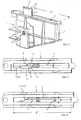
- the turnbuckle is still one in the edge area a wall component WE (see Fig.12) arranged, the Closing part 1 of the lock-forming housing 1 'with a bearing or a pivot shaft 2 for a latch part 3, which from the Housing 1 'by means of an actuator swing out and in this is founded upon the Housing 1 'by means of an actuator swing out and in this is founded upon the Housing 1 'by means of an actuator swing out and in this is founded at the Housing 1 'by means of an actuator swing out and in this is founded at the Housing 1 'by means of an actuator swing out and in this is Brightonschwenkbar and that, brought into tensioning position, with a Latch locking part 4 in the other, adjacent wall component WE 'is engaged.
- a wall component WE see Fig.12
- the latch latching part 4 is provided with a slot 7 corresponding to at least the width B of the cranked end 5, and this slot 7 is bounded by an engagement end 8 for the free end 5 of the latch member 3 and dimensioned with a length L larger than that Entry or exit slot length L 'on the housing 1 for the latch part.
- the latch member 3 is, as shown in Figures 4 and 6, relatively easy to punch out and bezgl. Their free, provided with chamfers 13 ends 5 are just as easyattentionkröpfen.
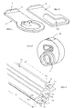
- Figure 7 represents a preferred embodiment of the latch locking part 4, namely in the form of a U-profile 9, the inwardly bent leg ends 10 define the slot 7 and one of which Schugreifungsrand 8 forms.
- Such locking latch parts 4 can be integrated into a construction panel or a wall component as a single piece with a length of, for example, 15 to 25 cm.
- a U-profile 9 is dimensioned with a length L "which corresponds to a multiple of the outlet slot length L 'on the housing 1.
- the bevel 13 at the bent end 5 of the latch part 3, the rest and advantageous at both ends of the bend 5 is provided, as in the two individual presentations the locking parts in Figs. 4 and 6 is illustrated, has its essential, functional meaning in that with it when opening the turnbuckle the latch part 3 automatically is reset axially, since the bevel 13 at Swiveling the bolt part back to the relevant slot edge runs.
- the arrangement of such bevel 13 advantageous also on the other side ensures thereby one smooth engagement in the slot 7 of the latch locking part 4th
- the latch latching part 4 is at a minimum width B of the right angle bent end 5 corresponding slot 7 provided, and this slot 7 is from a Deutschengreifungsrand 8 for the free end 5 of the latch part 3 is limited and is with a Length L is greater than the entry or exit slot length L 'on the housing 1 for the latch part 3. Also at this embodiment are bevels at the cranked end 5 bevels 13 provided to also here when swinging and swinging gegf. small existing fit inaccuracies too to encounter.
- FIGS provides exact positive guidance for both swivel movements
- the setting positions are shown I-III of the bolt part 3 by different lines clarified, with the here the eccentric comprehensive Hub of the bolt part 3 for the position II omitted is. Bezgl. this position positions I-III of the latch part FIG. 3 is also referred to FIG previously described cam adjustment of the latch part 3 illustrates are.
- latch locking part 4 As far as the so-called latch locking part 4 is concerned, the same advantageous embodiments described above can be used for this also in this context.
- the latch locking element 4 In order to continue to use lock parts from housings 1 with the usual hook-shaped latch parts, there is with respect to the latch locking element 4 is an advantageous development in that the latch locking part 4 spaced from each other transverse bolts 40 are arranged.
- the spaced arrangement of such transverse bolts 40 of which only one in dashed lines in Fig.7 is indicated with the latch locking part 4, of course, depends on the arrangement grid such hook-shaped latch parts in the adjacent wall element.
- turnbuckles as shown, for example, usually also at the upper and lower margins of the Wall components WB are involved, so that a strain of the elements also against accordingly appropriate equipped Make floor and ceiling elements of room cells to be created to be able to.
Landscapes
- Engineering & Computer Science (AREA)
- Architecture (AREA)
- Physics & Mathematics (AREA)
- Electromagnetism (AREA)
- Civil Engineering (AREA)
- Structural Engineering (AREA)
- Clamps And Clips (AREA)
- Compounds Of Unknown Constitution (AREA)
- Control Of Motors That Do Not Use Commutators (AREA)
- Polyesters Or Polycarbonates (AREA)
- Buckles (AREA)
- Gates (AREA)
- Mutual Connection Of Rods And Tubes (AREA)
Abstract
Description
Die Erfindung betrifft ein Spannschloß für die Verbindung von Wandbauelementen zur Erstellung von Raumzellen, bestehend aus einem im Randbereich eines Wandbauelementes angeordneten, das Schließteil des Schlosses bildenden Gehäuse mit einem Lager für ein Riegelteil, das aus dem Gehäuse mittels eines Stellgliedes ausschwenk- und in dieses rückschwenkbar ist und das, in Spannstellung gebracht, mit einem Riegelverrastungsteil im anderen, benachbarten Wandbauelement in Eingriff bringbar ist.The invention relates to a turnbuckle for the connection of Wall elements for creating space cells, consisting of one arranged in the edge region of a wall component, the Locking part of the lock forming housing with a bearing for a latch part coming out of the housing by means of an actuator swinging out and can be swung back into it and that, brought into clamping position, with a latch locking part in other, adjacent wall component can be brought into engagement.
Derartige Spannschlösser sind bspw. nach DE-A-20 09 838, DE-A-_
101 38 471, US-A-3,327,447 und US-A-2,738,211 bekannt. Die Gehäuse
solcher Spannschlösser sind in der Regel zu mehreren in
das Wärmedämmmaterial (bspw.Polyurethan) solcher Wandbauelemente
stirnseitig fluchtend eingebunden, wobei in einem Wandbauelement
das hakenartig ausgebildete und ausschwenkbare und
bspw. per Exzenterverstellung in Spannstellung bringbare, hakenartige
Riegelteil angeordnet ist, das dabei einen Verrastungsquerbolzen
im anderen, dicht anzuschließenden Wandbauelement
erfaßt und das Bauelement spannend an das andere heranzieht.
Der Querbolzen sitzt dabei in der Regel ebenfalls in
einem kleinen, ebenfalls im Randbereich des anderen Bauelementes
angeordneten Gehäuse. Diese Art der gegenseitigen Verspannung
zweier benachbarter Wandbauelemente verlangt bei deren
Herstellung eine genau fluchtende und nur mit Lehre zu erreichende
Zuordnung der Spannschloßteile, damit das hakenartige
Riegelteil mit Sicherheit und genau am Querbolzen des anzuschließenden
Wandbauelementes in spannenden Eingriff kommen
kann.
Durch diese zwingend genaue Zuordnung der Schloßteile ist man
aber auch, was die Zuordnung zweier Bauplatten betrifft, genau
auf diesen Zuordnungsraster festgelegt.
Eine Verschiebung bzw. ein Versatz der Wandbautelemente zueinander
ist dabei nicht möglich.Such turnbuckles are known, for example, from DE-A-20 09 838, DE-A-101 38 471, US Pat. No. 3,327,447 and US Pat. No. 2,738,211. The housing of such turnbuckles are usually in front of several in the thermal insulation material (polyurethane) such wall components integrated aligned, wherein in a wall component, the hook-like trained and swinging and, for example. By eccentric adjustable in clamping position, hook-like latch member is arranged, the one Verrastungsquerbolzen detected in the other, tightly connected wall component and the component attracts exciting to the other. The cross pin usually sits in a small, also arranged in the edge region of the other component housing. This type of mutual clamping of two adjacent wall components required in their preparation a precisely aligned and achievable only with teaching assignment of the turnbuckle parts, so that the hook-like latch part can come with security and exactly on the cross bolt of the wall element to be connected in exciting engagement.
By this compellingly accurate assignment of the cams but you also, as regards the assignment of two building panels, set exactly on this assignment grid.
A shift or an offset of the Wandbautelemente each other is not possible.
Um diesbezüglich freier bei der Zuordnung von Wandelementen beim Zellenbau gestalten zu können und außerdem nicht mehr bei der Herstellung solcher Bauplatten bzw. Wandbauelemente auf eine genau fluchtende Zuordnung der Schloßteile, d.h. vom Schließteil und vom Riegelteil angewiesen zu sein, liegt der Erfindung die Aufgabe zugrunde, ein Spannschloß der eingangs genannten Art dahingehnd umzugestalten und zu verbessern, daß diese Vorgaben erfüllt sind, und zwar verbunden mit der Maßgabe, daß das Riegelteil besser lastverteilend flächig am jeweils anderen Wandbauelement bzw. dessen Riegelverrastungsteil zur Anlage kommt.In this regard, more free in the assignment of wall elements to be able to shape the cell construction and also not at the production of such building panels or wall components a precisely aligned allocation of the cams, i. from Lock part and to be relied on the bolt part, is the Invention, the object of a turnbuckle the beginning to change and improve that kind these requirements are met, with the proviso that that the latch part better load-distributing area on each another wall component or its Latch Verrastungsteil comes to the plant.
Diese Aufgabe ist mit einem Spannschloß der eingangs genannten
Art nach der Erfindung mit einer ersten Art durch die im Kennzeichen
des unabhängigen Patentanspruches 1 angeführten Merkmale
gelöst und nach einer zweiten Art durch die Merkmale des
unabhängigen Patentanspruches 3, die sich von dem der ersten
Art nur durch eine etwas abgewandelte Art der axialen Querverstellung
des Riegelteiles unterscheidet.This object is achieved with a turnbuckle of the aforementioned
Type of the invention with a first kind by the in the license plate
of the
Da bei diesen Lösungen keine im herkömmlichen Sinne hakenartige,
in der Erstreckungsebene des Riegelteiles bleibende Verspannung
erfolgt, sondern demgegenüber mit einer rechtwinklig
abgekröpften, zur Flächenanlage zu bringenden Abkröpfungsleiste
des Riegelteiles, wird durch die axialen Verstellung des
Riegelteiles dafür gesorgt, daß beim Ausschwenken die Abkröpfung
den so schmal wie möglich zu haltenden Schlitz am
Gehäuse noch passieren kann, um danach beim Anziehen des Riegelteiles
die Abkröpfung am Riegelverrastungsteil zur Flächenanlage
zu bringen, wobei für das Rückschwenken bzw. Öffnen
eines solchen Schlosses durch einfache und noch näher zu
erläuternde Maßnahmen am Riegelteil und am Gehäuse, aber ohne
sonstige Hilfsmaßnahmen, wie Rückstellfedern oder biegeelastische
Ausbildung des Riegelteiles, die entsprechende axiale
Rückstellung des Riegelteiles gesorgt wird.
Außerdem ist bei beiden Lösungen kein fluchtend genau zu justierender
Querbolzen bzw. eine Eingriffsöffnung am gegenzuspannenden
Wandbauelement mehr vorhanden, und für die Verrastung
steht die ganze Länge des Hintergreifungsrandes am anderen
Element zur Verfügung, welches diesen Rand aufweisende,
hier sogenannte Riegelverrastungsteil, was noch näher erläutert
wird, vorteilhaft über die ganze Seitenrandlänge eines Wand
bauelementes erstreckt sein kann, wobei dieser Hintergreifungsrand
in konkreter Ausführungsform vorzugsweise in Form
eines u-Profiles ausgebildet ist, an dem die abgekröpften Enden
der Schenkel den bzw. die Hintergreifungsränder bilden. Es
kommen bspw. aber auch V- oder halbkreisförmige Profile in Betracht,
wobei auch da wesentlich ist, daß diese mindestens
einen den Eingriffsschlitz begrenzenden Hintergreifungsrand
aufweisen.Since in these solutions no hook-like in the conventional sense, remaining in the plane of extension of the latch part clamping takes place, but in contrast with a right-angled, to be applied to the surface abutment strip of the latch member is ensured by the axial adjustment of the latch member that when swinging the bend the as narrow as possible to be held slot on the housing still can happen to then bring when tightening the latch part, the bend on Riegelverrastungsteil for surface investment, for the pivoting back or opening of such a lock by simple and yet to be explained measures on the bolt part and on Housing, but without other supportive measures, such as return springs or flexurally elastic design of the latch member, the corresponding axial provision of the latch member is taken care of.
In addition, in both solutions no aligned exactly to be adjusted cross bolt or an engagement opening on gegenzuspannenden wall component more available, and for locking the whole length of Hintergreifungsrandes on the other element is available, which has this edge, here so-called Riegelverrastungsteil, which will be explained in more detail is advantageous over the entire side edge length of a wall member may be extended, said Hintergreifungsrand is formed in a concrete embodiment, preferably in the form of a U-profile at which the bent ends of the legs form the or the Hintergreifungsränder. But there are, for example, but also V- or semicircular profiles into consideration, where it is essential that they have at least one engagement slot limiting Hintergreifungsrand.
Das erfindungsgemäße Spannschloß und seine vorteilhaften Ausführungs-
und Weiterbildungsformen werden nachfolgend anhand
der zeichnerischen Darstellung von Ausführungsbeispielen näher
erläutert.
Es zeigt
- Fig.1
- perspektivisch das Spannschloßgehäuse mit ausgefahrenem Riegelteil in noch nicht vollzogener Spannstellung;
- Fig.2
- eine Draufsicht auf das Gehäuse gemäß Fig.1;
- Fig.3
- eine Draufsicht auf das Gehäuse mit eingeschwenktem Riegelteil;
- Fig.4
- perspektivisch eine Ausführungsform des Riegelteiles in Einzeldarstellung;
- Fig.5
- perspektivisch einen Stellexzenter für das Riegelteil gemäß Fig.4;
- Fig.6
- perspektivisch eine andere Ausführungsform des Riegelteiles:
- Fig.7
- perspektivisch das Riegelverrastungsteil in besonderer Ausführungsform;
- Fig.8
- schematisch eine besondere Ausführungsform des Riegelteiles;
- Fig.9
- eine Erläuterungsskizze zur Ausführungsform nach Fig.8;
- Fig.10
- schematisch die Stellpositionen des Riegelteiles bei einer Exzenterverstellung;
- Fig.11
- schematisiert und in Seitenansichten die Verstellpositionen bei Nockenverstellung des Riegelteiles gemäß Fig. 6 und
- Fig.12
- in Seitenansicht zwei zusammengespannte Wandbauelemente mit den in deren Randbereichen eingebundenen Schließ- und Riegelverrastungsteilen.
It shows
- Fig.1
- in perspective, the turnbuckle housing with extended latch part in not yet completed clamping position;
- Fig.2
- a plan view of the housing of Figure 1;
- Figure 3
- a plan view of the housing with pivoted-latch part;
- Figure 4
- perspective view of an embodiment of the latch member in an individual view;
- Figure 5
- in perspective, a location eccentric for the latch part according to Figure 4;
- Figure 6
- perspective another embodiment of the latch member:
- Figure 7
- in perspective, the latch locking part in a particular embodiment;
- Figure 8
- schematically a particular embodiment of the latch member;
- Figure 9
- an explanatory sketch for the embodiment of Figure 8;
- Figure 10
- schematically the parking positions of the latch member at an eccentric adjustment;
- Figure 11
- schematized and in side views the adjustment positions at cam adjustment of the latch member of FIG. 6 and
- Figure 12
- in side view two clamped wall components with the integrated in the edge regions locking and Latch latching parts.
Das Spannschloß besteht nach wie vor aus einem im Randbereich
eines Wandbauelementes WE (siehe Fig.12) angeordneten, das
Schließteil 1 des Schlosses bildenden Gehäuse 1' mit einem Lager
bzw. einer Schwenkwelle 2 für ein Riegelteil 3, das aus dem
Gehäuse 1' mittels eines Stellgliedes ausschwenk- und in dieses
rückschwenkbar ist und das, in Spannstellung gebracht, mit einem
Riegelverrastungsteil 4 im anderen, benachbarten Wandbauelement
WE' im Eingriff steht.The turnbuckle is still one in the edge area
a wall component WE (see Fig.12) arranged, the
Für ein solches Spannschloß nach der ersten Art ist nun nach
der Erfindung wesentlich, daß das freie Ende 5 des Riegelteiles
3 rechtwinklig abgekröpft und das Riegelteil 3 im Gehäuse 1'
auf seinem Lager axial verschieblich gelagert und im Gehäuse
1'eine dessen axiale Verschiebung beim Ausschwenken bewirkende
Rampe 6 angeordnet ist. Dabei ist das rechtwinklig abgekröpfte,
praktisch eine Anlageleiste bildende Ende 5 des Riegelteiles 3
in Bezug auf das Gehäuse 1 einschwenkseitig mit einer Anschrägung
13 versehen. Ferner ist das Riegelverrastungsteil 4
mit einem mindestens der Breite B des abgekröpften Endes 5
entsprechenden Schlitz 7 versehen, und dieser Schlitz 7 ist von
einem Hintergreifungsrand 8 für das freie Ende 5 des Riegelteiles
3 begrenzt und mit einer Länge L bemessen, die größer
ist als die Ein- bzw. Austrittsschlitzlänge L' am Gehäuse 1 für
das Riegelteil 3.
Beim Riegelteil 3 handelt es sich, wie aus Fig.4 und 6 ersichtlich,
um relativ breitflächige Laschenzuschnitte, die einfach
auszustanzen und bezgl. ihrer freien, mit Anschrägungen 13
versehenen Enden 5 ebenso einfach abzukröpfen sind.For such a turnbuckle according to the first type is now essential to the invention that the
The
Hierzu wird auf die Fig.1 bis 3 und 7 verwiesen, wobei die
Fig.7 eine bevorzugte Ausführungsform des Riegelverrastungsteiles
4 darstellt, nämlich in Form eines U-Profiles 9, dessen
nach innen abgekröpften Schenkelenden 10 den Schlitz 7 begrenzen
und von denen eines den Hintergreifungsrand 8 bildet.
Solche Riegelverrastungsteile 4 können zu mehreren stirnseitig
in einer Bauplatte bzw. eines Wandbauelementes als Einzelstücke
mit einer Länge von bspw. 15 bis 25 cm eingebunden sein. Bevorzugt
wird jedoch ein solches U-Profil 9 mit einer Länge L"
bemessen, die einem Vielfachen der Austrittsschlitzlänge L' am
Gehäuse 1 entspricht.
In der Praxis bedeutet dies, daß sich ein solches Profil 9 über
die ganze Länge eines Wandbauelementes WE erstrecken kann
(siehe Fig.12), dort also an jeder beliebigen Stelle des
Schlitzes 7 die Riegelteile 3 der Schloßgehäuse 1 im benachbarten
Wandbauelement WE eingreifen und unter Verspannung verrastet
werden können. Zwecks fester Einbindung in die Wärmedämmfüllung
von Wandbauelementen ist das U-Profil 9, wie ebenfalls
aus Fig.7 ersichtlich, an mindestens einer seiner
schlitzfreien Außenseiten 11 mit Einbindungsfortsätzen 12 versehen.Reference is made to Figures 1 to 3 and 7, wherein Figure 7 represents a preferred embodiment of the
In practice, this means that such a
Die Anschrägung 13 am abgekröpften Ende 5 des Riegelteiles 3,
die im übrigen und vorteilhaft an beiden Enden der Abkröpfung 5
vorgesehen wird, wie dies auch in den beiden Einzeldarstellungen
der Riegelteile in den Fig. 4 und 6 verdeutlicht ist,
hat ihre wesentliche, funktionelle Bedeutung darin, daß damit
beim Öffnen des Spannschlosses das Riegelteil 3 automatisch
wieder axial zurückgestellt wird, da die Anschrägung 13 beim
Zurückschwenken des Riegelteiles auf die betreffende Schlitzkante
aufläuft. Die Anordnung einer solchen Anschrägung 13
vorteilhaft auch auf der anderen Seite sorgt dabei für einen
reibungslosen Eingriff in den Schlitz 7 des Riegelverrastungsteiles
4.The
An der Konstruktion des eigentlichen Schließteiles, d.h., des
Gehäuses 1 mit dem aus- und einschwenkbaren Riegelteil 3 ändert
sich praktisch nichts, dessen Ein- und Ausschwenkung nach wie
vor mit einem außem an der Schwenkwelle 2' ansetzbaren Steckschlüssel
erfolgt.On the construction of the actual closing part, i.e., the
Dieses Aus- und Einschwenken kann sowohl mit einem Riegelteil 3
gemäß Fig.4 und zugehörigem Exzenter gemäß Fig.5 erfolgen als
auch bevorzugt, da einfacher herstellbar, mit einem Riegelteil
3, das mit einer dessen Nabe bildenden rechtwinkligen Ausnehmung
3" versehen ist, die von einer drehbar im Gehäuse 1
gelagerten und mit einem in die Ausnehmung 3" eingreifenden
Stellnocken 50 versehenen Schwenkwelle 2 durchgriffen ist. Zu
dieser bevorzugten Ausführungsform wird auf Fig. 11 verwiesen,
die im übrigen von links nach rechte die Einzugsstellung, die
Ausschwenkstellung und die Spannstellung des Riegelteiles 3 in
der Ausführungsform gemäß Fig.6 verdeutlicht.This swinging in and out can both with a latch part. 3
4 and associated eccentric according to Figure 5 take place as
also preferred because easier to produce, with a
Auch die funktionelle Zuordnung des in Fig.4 ebenfalls der
Vollständigkeit halber mit dargestellten Riegelteiles 3 zum mit
einem federbelasteten Mitnehmers 30 versehenen Exzenter ändert
sich nichts, wobei der Mitnehmer 30 in angepaßte Rasten 31 am
Riegelteil 3 eingreift.The functional assignment of the in Fig.4 also the
For the sake of completeness with illustrated
Änderungen liegen aber bei beiden Ausführungsformen der Riegelteile
3 insoweit vor, als das Riegelteil 3 auf dem Exzenter
bzw. der Schwenkwelle 2 mit ihrem Stellnocken 50 bis zu einem
gewissen Grade axial querverschieblich gelagert und das Riegelteil
3 nicht mehr als Haken ausgebildet ist, sondern, wie
aus Fig.4,6 ersichtlich, mit einem abgekröpften Ende 5, mit dem
im Spannzustand der Hintergreifungsrand 8 am Riegelverrastungsteil
4 unter flächiger Auflage am Hintergreifungsrand 8
erfaßt wird.However, changes are in both embodiments of the
Um den axialen Versatz des Riegelteiles 3 zu bewirken, damit
dieser nach Passage des Schlitzes 7 in Hintergreifungsposition
zum Rand 8 gelangt (siehe Fig.2), besteht eine weitere aber von
der vorbeschriebenen nur geringfügig abweichende Lösung unter
Verweis auf die Fig. 8-10 darin, daß das freie Ende 5 des
Riegelteiles 3 in gleicher Weise wie vorbeschrieben rechtwinklig
abgekröpft und das Riegelteil 3 im Gehäuse 1' auf seinem
Lager 2 axial verschieblich gelagert ist. Hierbei ist jedoch
der in allen Stellungen im Gehäuse 1 verbleibende Abschnitt
des Riegelteil 3 beidseitig mit einem Kulissenvorsprung
16 versehen, welche Vorsprünge 16 an beiden benachbarten Gehäuseinnenwänden
1', 1'' in Führungsnuten 17,18 eingreifen, deren
Böden 19 mit die axialen Verstellungen des Riegelteiles 3
bewirkenden Neigungen versehen sind. Das Riegelverrastungsteil
4 ist dabei mit einem mindestens der Breite B des rechtwinklig
abgekröpften Endes 5 entsprechenden Schlitz 7 versehen, und
dieser Schlitz 7 wird von einem Hintergreifungsrand 8 für das
freie Ende 5 des Riegelteiles 3 begrenzt und ist mit einer
Länge L bemessen, die größer ist als die Ein- bzw. Austrittsschlitzlänge
L' am Gehäuse 1 für das Riegelteil 3. Auch bei
dieser Ausführungsform werden am abgekröpften Ende 5 Anschrägungen
13 vorgesehen, um auch hier beim Aus- und Einschwenken
gegf. kleinen vorhandenen Passungsungenauigkeiten zu
begegnen.In order to effect the axial displacement of the
Dies ist stark schematisiert in den Fig.8,9 verdeutlicht und
stellt für beide Schwenkbewegungen eine exakte Zwangsführung
dar. In Fig. 9 sind übrigens aus Übersichtsgründen die Stellpositionen
I-III des Riegelteiles 3 durch unterschiedliche Linienführungen
verdeutlicht, wobei die hier den Exzenter umfassende
Nabe des Riegelteiles 3 für die Stellung II weggelassen
ist. Bezgl. dieser Stellungspositionen I-III des Riegelteiles
3 wird auch auf Fig.11 verwiesen, die dort anhand der
vorbeschriebenen Nockenverstellung des Riegelteiles 3 verdeutlicht
sind.This is illustrated very schematically in FIGS
provides exact positive guidance for both swivel movements
In FIG. 9, by the way, for reasons of clarity, the setting positions are shown
I-III of the
Was dabei das hier sogenannte Riegelverrastungsteil 4 betrifft,
so können für dieses auch in diesem Zusammenhang die gleichen
vorbeschriebenen vorteilhaften Ausführungsformen zur Anwendung
kommen.
Um auch Schloßteile aus Gehäusen 1 mit den bisher üblichen
hakenförmige Riegelteilen weiter verwenden zu können, besteht
bzgl. des Riegelverrastungselementes 4 eine vorteilhafte Weiterbildung
darin, daß im Riegelverrastungsteil 4 beabstandet
zueinander Querbolzen 40 angeordnet sind.
Die beabstandete Anordnung solcher Querbolzen 40, von denen nur
einer in Fig.7 gestrichelt mit am Riegelverrastungsteil 4 angedeutet
ist, richtet sich natürlich nach dem Anordnungsraster
solcher hakenförmiger Riegelteile im benachbarten Wandelement.As far as the so-called
In order to continue to use lock parts from
The spaced arrangement of such
Abschließend sei unter Bezug auf Fig.12 noch darauf hingewiesen, daß derartige Spannschlösser, wie bspw. dargestellt, in der Regel auch an den oberen und unteren Seitenränder der Wandbauelemente WB eingebunden sind, um damit eine Verspannung der Elemente auch gegen sinngemäß entsprechende ausgestattete Boden- und Deckenelemente von zu erstellenden Raumzellen vornehmen zu können.Finally, with reference to FIG. 12, it should be noted that that such turnbuckles, as shown, for example, usually also at the upper and lower margins of the Wall components WB are involved, so that a strain of the elements also against accordingly appropriate equipped Make floor and ceiling elements of room cells to be created to be able to.
Claims (10)
dadurch gekennzeichnet, daß das freie Ende (5) des Riegelteiles (3) rechtwinklig abgekröpft und das Riegelteil (3) im Gehäuse (1') auf seinem Lager (2) axial verschieblich gelagert und im Gehäuse (1') eine dessen axiale Verschiebung beim Ausschwenken bewirkende Rampe(6) angeordnet ist, wobei das rechtwinklig abgekröpfte Ende (5) des Riegelteiles (3) in Bezug auf das Gehäuse (1) einschwenkseitig mit einer Anschrägung (13) versehen ist, und daß das Riegelverrastungsteil (4) mit einem mindestens der Breite (B) des abgeknickten Endes (5) entsprechenden Schlitz (7) versehen und dieser Schlitz (7) von einem Hintergreifungsrand (8) für das freie Ende (5) des Riegelteiles (3) begrenzt und mit einer Länge (L) bemessen ist, die größer ist als die Ein- bzw. Austrittsschlitzlänge (L') am Gehäuse (1) für das Riegelteil (3).Turnbuckle for the connection of wall components for creating space cells, consisting of a in the edge region of a wall component (WE) arranged, the closing part (1) of the lock forming housing (1 ') with a bearing (2) for a latch part (3), the from the housing (1 ') by means of an actuator swing out and is zurückschwenkbar in this and that, brought into clamping position, with a latch locking part (4) in the other, adjacent wall component (WE') is engaged,
characterized in that the free end (5) of the latch member (3) bent at right angles and the latch member (3) in the housing (1 ') mounted axially displaceably on its bearing (2) and in the housing (1') one of its axial displacement Pivoting effect causing ramp (6) is arranged, wherein the right-angled bent end (5) of the latch part (3) with respect to the housing (1) is pivotally provided with a chamfer (13), and in that the latch locking part (4) with an at least the width (B) of the bent end (5) corresponding slot (7) provided and this slot (7) of a Hintergreifungsrand (8) for the free end (5) of the latch part (3) limited and dimensioned with a length (L) is greater than the entry or exit slot length (L ') on the housing (1) for the latch part (3).
dadurch gekennzeichnet, daß das abgekröpfte Ende (5) des Riegelteiles (3) auch auf der anderen Seite mit einer Anschrägung (13') versehen ist. Turnbuckle according to claim 1,
characterized in that the cranked end (5) of the latch part (3) is also provided on the other side with a chamfer (13 ').
dadurch gekennzeichnet, daß das freie Ende (5) des Riegelteiles (3) rechtwinklig abgekröpft und das Riegelteil (3) im Gehäuse (1') auf seinem Lager (2) axial verschieblich gelagert und daß der in allen Stellungen im Gehäuse (1) verbleibende Abschnitt des Riegelteil (3) beidseitig mit einem Kulissenvorsprung (16) versehen ist, welche Vorsprünge (16) an beiden benachbarten Gehäuseinnenwänden (1',1'') in Führungsnuten (17,18) eingreifen, deren Böden (19) mit die axialen Verstellungen des Riegelteiles (3) bewirkenden Neigungen versehen sind, und daß das Riegelverrastungsteil (4) mit einem mindestens der Breite (B) des rechtwinklig abgekröpften Endes (5) entsprechenden Schlitz (7) versehen und dieser Schlitz (7) von einem Hintergreifungsrand (8) für das freie Ende (5) des Riegelteiles (3) begrenzt und mit einer Länge (L) bemessen ist, die größer ist als die Ein- bzw. Austrittsschlitzlänge (L') am Gehäuse (1) für das Riegelteil (3).Turnbuckle for the connection of wall components for creating space cells, consisting of a in the edge region of a wall component (WE) arranged, the closing part (1) of the lock forming housing (1 ') with a bearing (2) for a latch part (3), the from the housing (1 ') by means of an actuator swing out and is zurückschwenkbar in this and that, brought into clamping position, with a latch locking part (4) in the other, adjacent wall component (WE') is engaged,
characterized in that the free end (5) of the latch member (3) bent at right angles and the latch member (3) in the housing (1 ') mounted axially displaceably on its bearing (2) and that in all positions in the housing (1) remaining Section of the latch part (3) is provided on both sides with a slide projection (16), which projections (16) on both adjacent housing inner walls (1 ', 1'') in guide grooves (17,18) engage their bottoms (19) with the axial 3) are provided with inclinations, and in that the latch locking part (4) is provided with a slot (7) corresponding at least to the width (B) of the right-angled end (5) and this slot (7) is provided by an engagement edge (8) ) is bounded for the free end (5) of the latch part (3) and dimensioned with a length (L) which is greater than the entry or exit slot length (L ') on the housing (1) for the latch part (3).
dadurch gekennzeichnet, daß das abgekröpfte Ende (5) des Riegelteiles (3) an beiden Flanken mit Anschrägungen (13,13') versehen ist.Turnbuckle according to claim 3,
characterized in that the cranked end (5) of the latch part (3) is provided on both flanks with chamfers (13,13 ').
dadurch gekennzeichnet, daß das Riegelverrastungsteil (4) in Form eines U-Profiles (9) ausgebildet ist, dessen nach innen abgekröpften Schenkelenden (10) den Schlitz (7) begrenzen, von denen eines den Hintergreifungsrand (8) bildet. Turnbuckle according to one of claims 1 to 4,
characterized in that the latch latching part (4) in the form of a U-profile (9) is formed, the inwardly bent leg ends (10) defining the slot (7), one of which forms the Hintergreifungsrand (8).
dadurch gekennzeichnet, daß das U-Profil (9) mit einer Länge (L") bemessen ist, die einem Vielfachen der Austrittsschlitzlänge (L') am Gehäuse (1) entspricht.Turnbuckle according to claim 5,
characterized in that the U-profile (9) is dimensioned with a length (L ") which corresponds to a multiple of the outlet slot length (L ') on the housing (1).
dadurchg gekennzeichnet,
daß das U-Profil (9) an mindestens einer seiner schlitzfreien Außenseiten (11) mit Einbindungsfortsätzen (12) versehen ist.Turnbuckle according to claim 5 or 6,
characterized g characterized
that the U-profile (9) is provided on at least one of its slot-free outer sides (11) with Einindungsfortsätzen (12).
dadurch gekennzeichnet, daß im Riegelverrastungsteil (4) beabstandet zueinander Querbolzen (40) angeordnet sind.Turnbuckle according to one of claims 5 to 7,
characterized in that in the latch latching part (4) spaced from each other transverse bolt (40) are arranged.
dadurch gekennzeichnet, daß das Riegelteil (3) mit seiner Nabe (3') auf einem im Gehäuse (1) drehbar gelagerten Stellexzenter (2) gelagert ist.Turnbuckle according to one of claims 1 to 8,
characterized in that the locking part (3) with its hub (3 ') on a in the housing (1) rotatably mounted adjusting eccentric (2) is mounted.
dadurch gekennzeichnet, daß das Riegelteil (3) mit einer dessen Nabe bildenden rechtwinkligen Ausnehmung (3") versehen ist, die von einer drehbar im Gehäuse (1) gelagerten und mit einem in die Ausnehmung (3") eingreifenden Stellnocken (50) versehenen Schwenkwelle (2) durchgriffen ist.Turnbuckle according to one of claims 1 to 8,
characterized in that the latch member (3) is provided with a hub forming its rectangular recess (3 "), of a rotatably mounted in the housing (1) and with a in the recess (3") engaging adjusting cam (50) provided pivot shaft (2) is enforced.
Applications Claiming Priority (2)
| Application Number | Priority Date | Filing Date | Title |
|---|---|---|---|
| DE10318940 | 2003-04-26 | ||
| DE10318940A DE10318940A1 (en) | 2003-04-26 | 2003-04-26 | Turnbuckle especially for connecting wall components |
Publications (3)
| Publication Number | Publication Date |
|---|---|
| EP1471190A2 true EP1471190A2 (en) | 2004-10-27 |
| EP1471190A3 EP1471190A3 (en) | 2004-11-17 |
| EP1471190B1 EP1471190B1 (en) | 2005-10-05 |
Family
ID=32946443
Family Applications (1)
| Application Number | Title | Priority Date | Filing Date |
|---|---|---|---|
| EP04009481A Expired - Lifetime EP1471190B1 (en) | 2003-04-26 | 2004-04-22 | Clamping mechanism |
Country Status (5)
| Country | Link |
|---|---|
| EP (1) | EP1471190B1 (en) |
| AT (1) | ATE305998T1 (en) |
| DE (2) | DE10318940A1 (en) |
| DK (1) | DK1471190T3 (en) |
| ES (1) | ES2250938T3 (en) |
Families Citing this family (1)
| Publication number | Priority date | Publication date | Assignee | Title |
|---|---|---|---|---|
| CN108678277B (en) * | 2018-08-09 | 2024-01-26 | 浙江新远见木塑材料有限公司 | T-shaped self-locking type combined wood-plastic plate |
Citations (4)
| Publication number | Priority date | Publication date | Assignee | Title |
|---|---|---|---|---|
| US2924089A (en) * | 1958-03-03 | 1960-02-09 | Gateway Engineering Company | Hinged clip hanger for dovetail channel structure |
| EP0085998A1 (en) * | 1982-01-18 | 1983-08-17 | Pvba Isocab S.P.R.L. | Interlocking device for the joining together of two elements placed opposite one another |
| US6119427A (en) * | 1998-04-29 | 2000-09-19 | Louisville Cooler Manufacturing Co. | Apparatus and method of modular panel construction |
| US6299224B1 (en) * | 1999-09-01 | 2001-10-09 | Kason Industries, Inc. | Panel fastener |
Family Cites Families (6)
| Publication number | Priority date | Publication date | Assignee | Title |
|---|---|---|---|---|
| US2738211A (en) * | 1952-03-26 | 1956-03-13 | Schlueter Ernest | Lockable hook type fastener |
| US3327447A (en) * | 1965-04-22 | 1967-06-27 | Traulsen & Co Inc | Interlocking joint for abutted edges of insulated panel sections |
| DE2009838C3 (en) * | 1970-03-03 | 1974-01-24 | Steinbach & Vollmann Kg, 5628 Heiligenhaus | Device for connecting plate-shaped components |
| DE9113128U1 (en) * | 1991-10-12 | 1992-01-02 | Bollig, Hans Günter, Dr., 4000 Düsseldorf | Frame made of profile rods connected with connecting locks |
| DE4207644A1 (en) * | 1992-03-11 | 1993-09-23 | Preform Raumgliederungssysteme | WALL ELEMENT |
| DE19500340C1 (en) * | 1995-01-07 | 1996-05-02 | Vieler Gerd & Bernd Kg | Frame made from detachably connected shaped rods |
-
2003
- 2003-04-26 DE DE10318940A patent/DE10318940A1/en not_active Ceased
-
2004
- 2004-04-22 DE DE502004000081T patent/DE502004000081D1/en not_active Expired - Lifetime
- 2004-04-22 EP EP04009481A patent/EP1471190B1/en not_active Expired - Lifetime
- 2004-04-22 ES ES04009481T patent/ES2250938T3/en not_active Expired - Lifetime
- 2004-04-22 DK DK04009481T patent/DK1471190T3/en active
- 2004-04-22 AT AT04009481T patent/ATE305998T1/en not_active IP Right Cessation
Patent Citations (4)
| Publication number | Priority date | Publication date | Assignee | Title |
|---|---|---|---|---|
| US2924089A (en) * | 1958-03-03 | 1960-02-09 | Gateway Engineering Company | Hinged clip hanger for dovetail channel structure |
| EP0085998A1 (en) * | 1982-01-18 | 1983-08-17 | Pvba Isocab S.P.R.L. | Interlocking device for the joining together of two elements placed opposite one another |
| US6119427A (en) * | 1998-04-29 | 2000-09-19 | Louisville Cooler Manufacturing Co. | Apparatus and method of modular panel construction |
| US6299224B1 (en) * | 1999-09-01 | 2001-10-09 | Kason Industries, Inc. | Panel fastener |
Also Published As
| Publication number | Publication date |
|---|---|
| EP1471190B1 (en) | 2005-10-05 |
| ATE305998T1 (en) | 2005-10-15 |
| DK1471190T3 (en) | 2006-01-30 |
| EP1471190A3 (en) | 2004-11-17 |
| ES2250938T3 (en) | 2006-04-16 |
| DE502004000081D1 (en) | 2006-02-16 |
| DE10318940A1 (en) | 2004-11-25 |
Similar Documents
| Publication | Publication Date | Title |
|---|---|---|
| EP0310546B1 (en) | Variable arrangement of framework assembly | |
| EP2873792B1 (en) | Hinges | |
| DE2624429B2 (en) | Clamping means | |
| DE19717184B4 (en) | drawer | |
| DE3603453C2 (en) | ||
| DE2919190A1 (en) | DOOR STRAP FOR PIVOTING FASTENING, ESPECIALLY A VEHICLE DOOR | |
| DE10217534A1 (en) | Locking device for steering column adjuster unit in motor vehicles has locking part moved by control unit at right angles to clamping position, when tooth tips of locking and counter parts are in contact in blocking position | |
| DE2531685A1 (en) | SEALING FOR TWO PANEL-SHAPED ELEMENTS | |
| DE3141158C2 (en) | Guide device for a retractable and retractable insert in the body of a cabinet | |
| DE69208864T2 (en) | Device for fastening a guide shoe on the lower part of an elevator sliding door | |
| EP4341566A1 (en) | Connection fitting for connecting two furniture parts, corresponding connection fitting and corresponding furniture assembly | |
| EP1471190B1 (en) | Clamping mechanism | |
| DE3602686A1 (en) | Connecting element for frameworks | |
| DE19937892C1 (en) | Switch cabinet mounting rail fixing device uses holder attached to cabinet frame profile with toothed section cooperating with toothed section of bolt element for mounting rail to provide height adjustment | |
| DE2824301C2 (en) | Device for connecting a window blind or a door frame to a roller shutter box | |
| DE102006001045B4 (en) | Corner connector for door or window frame | |
| DE3706236C2 (en) | Connection element for two supporting parts | |
| EP0791759A1 (en) | Quick-release fastener | |
| EP2017483B1 (en) | Profile construction | |
| EP3137699B1 (en) | Method for producing a post-and-beam connection | |
| DE202014003122U1 (en) | Technical toy construction kit wood - plastic | |
| DE3517306A1 (en) | Device for aligning shuttering elements arranged next to one another | |
| EP3816366B1 (en) | Supporting structure with multiple elongate profile elements | |
| EP1126110B1 (en) | Locking device for doors and windows | |
| EP2997315A2 (en) | System for assembling two components |
Legal Events
| Date | Code | Title | Description |
|---|---|---|---|
| PUAI | Public reference made under article 153(3) epc to a published international application that has entered the european phase |
Free format text: ORIGINAL CODE: 0009012 |
|
| PUAL | Search report despatched |
Free format text: ORIGINAL CODE: 0009013 |
|
| AK | Designated contracting states |
Kind code of ref document: A2 Designated state(s): AT BE BG CH CY CZ DE DK EE ES FI FR GB GR HU IE IT LI LU MC NL PL PT RO SE SI SK TR |
|
| AX | Request for extension of the european patent |
Extension state: AL HR LT LV MK |
|
| AK | Designated contracting states |
Kind code of ref document: A3 Designated state(s): AT BE BG CH CY CZ DE DK EE ES FI FR GB GR HU IE IT LI LU MC NL PL PT RO SE SI SK TR |
|
| AX | Request for extension of the european patent |
Extension state: AL HR LT LV MK |
|
| RIC1 | Information provided on ipc code assigned before grant |
Ipc: 7F 16B 12/20 B Ipc: 7E 04B 1/61 A |
|
| 17P | Request for examination filed |
Effective date: 20041122 |
|
| GRAP | Despatch of communication of intention to grant a patent |
Free format text: ORIGINAL CODE: EPIDOSNIGR1 |
|
| GRAS | Grant fee paid |
Free format text: ORIGINAL CODE: EPIDOSNIGR3 |
|
| AKX | Designation fees paid |
Designated state(s): AT BE BG CH CY CZ DE DK EE ES FI FR GB GR HU IE IT LI LU MC NL PL PT RO SE SI SK TR |
|
| GRAA | (expected) grant |
Free format text: ORIGINAL CODE: 0009210 |
|
| AK | Designated contracting states |
Kind code of ref document: B1 Designated state(s): AT BE BG CH CY CZ DE DK EE ES FI FR GB GR HU IE IT LI LU MC NL PL PT RO SE SI SK TR |
|
| PG25 | Lapsed in a contracting state [announced via postgrant information from national office to epo] |
Ref country code: RO Free format text: LAPSE BECAUSE OF FAILURE TO SUBMIT A TRANSLATION OF THE DESCRIPTION OR TO PAY THE FEE WITHIN THE PRESCRIBED TIME-LIMIT Effective date: 20051005 Ref country code: PL Free format text: LAPSE BECAUSE OF FAILURE TO SUBMIT A TRANSLATION OF THE DESCRIPTION OR TO PAY THE FEE WITHIN THE PRESCRIBED TIME-LIMIT Effective date: 20051005 Ref country code: SK Free format text: LAPSE BECAUSE OF FAILURE TO SUBMIT A TRANSLATION OF THE DESCRIPTION OR TO PAY THE FEE WITHIN THE PRESCRIBED TIME-LIMIT Effective date: 20051005 Ref country code: SI Free format text: LAPSE BECAUSE OF FAILURE TO SUBMIT A TRANSLATION OF THE DESCRIPTION OR TO PAY THE FEE WITHIN THE PRESCRIBED TIME-LIMIT Effective date: 20051005 |
|
| REG | Reference to a national code |
Ref country code: GB Ref legal event code: FG4D Free format text: NOT ENGLISH |
|
| REG | Reference to a national code |
Ref country code: CH Ref legal event code: EP |
|
| REG | Reference to a national code |
Ref country code: SE Ref legal event code: TRGR |
|
| REG | Reference to a national code |
Ref country code: IE Ref legal event code: FG4D Free format text: LANGUAGE OF EP DOCUMENT: GERMAN |
|
| REG | Reference to a national code |
Ref country code: CH Ref legal event code: NV Representative=s name: PATENTANWALTSBUERO DR. URS FALK |
|
| GBT | Gb: translation of ep patent filed (gb section 77(6)(a)/1977) |
Effective date: 20051130 |
|
| PG25 | Lapsed in a contracting state [announced via postgrant information from national office to epo] |
Ref country code: BG Free format text: LAPSE BECAUSE OF FAILURE TO SUBMIT A TRANSLATION OF THE DESCRIPTION OR TO PAY THE FEE WITHIN THE PRESCRIBED TIME-LIMIT Effective date: 20060105 |
|
| REG | Reference to a national code |
Ref country code: DK Ref legal event code: T3 |
|
| REG | Reference to a national code |
Ref country code: GR Ref legal event code: EP Ref document number: 20050403633 Country of ref document: GR |
|
| REF | Corresponds to: |
Ref document number: 502004000081 Country of ref document: DE Date of ref document: 20060216 Kind code of ref document: P |
|
| REG | Reference to a national code |
Ref country code: ES Ref legal event code: FG2A Ref document number: 2250938 Country of ref document: ES Kind code of ref document: T3 |
|
| ET | Fr: translation filed | ||
| REG | Reference to a national code |
Ref country code: HU Ref legal event code: AG4A Ref document number: E000236 Country of ref document: HU |
|
| PG25 | Lapsed in a contracting state [announced via postgrant information from national office to epo] |
Ref country code: MC Free format text: LAPSE BECAUSE OF NON-PAYMENT OF DUE FEES Effective date: 20060430 |
|
| PLBE | No opposition filed within time limit |
Free format text: ORIGINAL CODE: 0009261 |
|
| STAA | Information on the status of an ep patent application or granted ep patent |
Free format text: STATUS: NO OPPOSITION FILED WITHIN TIME LIMIT |
|
| 26N | No opposition filed |
Effective date: 20060706 |
|
| PGFP | Annual fee paid to national office [announced via postgrant information from national office to epo] |
Ref country code: FI Payment date: 20080312 Year of fee payment: 5 Ref country code: PT Payment date: 20080314 Year of fee payment: 5 |
|
| PG25 | Lapsed in a contracting state [announced via postgrant information from national office to epo] |
Ref country code: EE Free format text: LAPSE BECAUSE OF FAILURE TO SUBMIT A TRANSLATION OF THE DESCRIPTION OR TO PAY THE FEE WITHIN THE PRESCRIBED TIME-LIMIT Effective date: 20051005 |
|
| PG25 | Lapsed in a contracting state [announced via postgrant information from national office to epo] |
Ref country code: LU Free format text: LAPSE BECAUSE OF NON-PAYMENT OF DUE FEES Effective date: 20060422 |
|
| PGFP | Annual fee paid to national office [announced via postgrant information from national office to epo] |
Ref country code: CH Payment date: 20080520 Year of fee payment: 5 Ref country code: CZ Payment date: 20080420 Year of fee payment: 5 Ref country code: DK Payment date: 20080425 Year of fee payment: 5 Ref country code: HU Payment date: 20080401 Year of fee payment: 5 |
|
| PGFP | Annual fee paid to national office [announced via postgrant information from national office to epo] |
Ref country code: AT Payment date: 20080429 Year of fee payment: 5 |
|
| PGFP | Annual fee paid to national office [announced via postgrant information from national office to epo] |
Ref country code: BE Payment date: 20080416 Year of fee payment: 5 Ref country code: TR Payment date: 20080327 Year of fee payment: 5 |
|
| PGFP | Annual fee paid to national office [announced via postgrant information from national office to epo] |
Ref country code: IE Payment date: 20080408 Year of fee payment: 5 Ref country code: NL Payment date: 20080620 Year of fee payment: 5 Ref country code: SE Payment date: 20080416 Year of fee payment: 5 |
|
| PG25 | Lapsed in a contracting state [announced via postgrant information from national office to epo] |
Ref country code: CY Free format text: LAPSE BECAUSE OF FAILURE TO SUBMIT A TRANSLATION OF THE DESCRIPTION OR TO PAY THE FEE WITHIN THE PRESCRIBED TIME-LIMIT Effective date: 20051005 |
|
| PGFP | Annual fee paid to national office [announced via postgrant information from national office to epo] |
Ref country code: GR Payment date: 20080331 Year of fee payment: 5 |
|
| PGFP | Annual fee paid to national office [announced via postgrant information from national office to epo] |
Ref country code: ES Payment date: 20090324 Year of fee payment: 6 |
|
| REG | Reference to a national code |
Ref country code: PT Ref legal event code: MM4A Free format text: LAPSE DUE TO NON-PAYMENT OF FEES Effective date: 20091022 |
|
| BERE | Be: lapsed |
Owner name: *VIESSMANN KALTETECHNIK A.G. Effective date: 20090430 |
|
| REG | Reference to a national code |
Ref country code: CH Ref legal event code: PL |
|
| REG | Reference to a national code |
Ref country code: DK Ref legal event code: EBP |
|
| EUG | Se: european patent has lapsed | ||
| NLV4 | Nl: lapsed or anulled due to non-payment of the annual fee |
Effective date: 20091101 |
|
| PG25 | Lapsed in a contracting state [announced via postgrant information from national office to epo] |
Ref country code: CH Free format text: LAPSE BECAUSE OF NON-PAYMENT OF DUE FEES Effective date: 20090430 Ref country code: AT Free format text: LAPSE BECAUSE OF NON-PAYMENT OF DUE FEES Effective date: 20090422 Ref country code: FI Free format text: LAPSE BECAUSE OF NON-PAYMENT OF DUE FEES Effective date: 20090422 Ref country code: CZ Free format text: LAPSE BECAUSE OF NON-PAYMENT OF DUE FEES Effective date: 20090422 Ref country code: LI Free format text: LAPSE BECAUSE OF NON-PAYMENT OF DUE FEES Effective date: 20090430 Ref country code: HU Free format text: LAPSE BECAUSE OF NON-PAYMENT OF DUE FEES Effective date: 20090423 |
|
| REG | Reference to a national code |
Ref country code: IE Ref legal event code: MM4A |
|
| PG25 | Lapsed in a contracting state [announced via postgrant information from national office to epo] |
Ref country code: NL Free format text: LAPSE BECAUSE OF NON-PAYMENT OF DUE FEES Effective date: 20091101 |
|
| PG25 | Lapsed in a contracting state [announced via postgrant information from national office to epo] |
Ref country code: PT Free format text: LAPSE BECAUSE OF NON-PAYMENT OF DUE FEES Effective date: 20091022 |
|
| PG25 | Lapsed in a contracting state [announced via postgrant information from national office to epo] |
Ref country code: DK Free format text: LAPSE BECAUSE OF NON-PAYMENT OF DUE FEES Effective date: 20090430 Ref country code: IE Free format text: LAPSE BECAUSE OF NON-PAYMENT OF DUE FEES Effective date: 20090422 |
|
| PG25 | Lapsed in a contracting state [announced via postgrant information from national office to epo] |
Ref country code: BE Free format text: LAPSE BECAUSE OF NON-PAYMENT OF DUE FEES Effective date: 20090430 |
|
| PG25 | Lapsed in a contracting state [announced via postgrant information from national office to epo] |
Ref country code: GR Free format text: LAPSE BECAUSE OF NON-PAYMENT OF DUE FEES Effective date: 20091104 |
|
| PG25 | Lapsed in a contracting state [announced via postgrant information from national office to epo] |
Ref country code: SE Free format text: LAPSE BECAUSE OF NON-PAYMENT OF DUE FEES Effective date: 20090423 |
|
| REG | Reference to a national code |
Ref country code: ES Ref legal event code: FD2A Effective date: 20110711 |
|
| PG25 | Lapsed in a contracting state [announced via postgrant information from national office to epo] |
Ref country code: ES Free format text: LAPSE BECAUSE OF NON-PAYMENT OF DUE FEES Effective date: 20110629 |
|
| PG25 | Lapsed in a contracting state [announced via postgrant information from national office to epo] |
Ref country code: ES Free format text: LAPSE BECAUSE OF NON-PAYMENT OF DUE FEES Effective date: 20100423 |
|
| PG25 | Lapsed in a contracting state [announced via postgrant information from national office to epo] |
Ref country code: TR Free format text: LAPSE BECAUSE OF NON-PAYMENT OF DUE FEES Effective date: 20090422 |
|
| REG | Reference to a national code |
Ref country code: DE Ref legal event code: R082 Ref document number: 502004000081 Country of ref document: DE Representative=s name: ANWALTSSOZIETAET MARYNIOK & EICHSTAEDT GBR, DE |
|
| REG | Reference to a national code |
Ref country code: DE Ref legal event code: R082 Ref document number: 502004000081 Country of ref document: DE Representative=s name: ANWALTSSOZIETAET MARYNIOK & EICHSTAEDT GBR, DE Effective date: 20130626 Ref country code: DE Ref legal event code: R081 Ref document number: 502004000081 Country of ref document: DE Owner name: VIESSMANN KAELTETECHNIK GMBH, DE Free format text: FORMER OWNER: VIESSMANN KAELTETECHNIK AG, 95030 HOF, DE Effective date: 20130626 Ref country code: DE Ref legal event code: R081 Ref document number: 502004000081 Country of ref document: DE Owner name: VIESSMANN KUEHLSYSTEME GMBH, DE Free format text: FORMER OWNER: VIESSMANN KAELTETECHNIK AG, 95030 HOF, DE Effective date: 20130626 Ref country code: DE Ref legal event code: R082 Ref document number: 502004000081 Country of ref document: DE Representative=s name: MARYNIOK GBR PATENT- UND RECHTSANWALTSSOZIETAE, DE Effective date: 20130626 Ref country code: DE Ref legal event code: R082 Ref document number: 502004000081 Country of ref document: DE Representative=s name: DIE PATENTERIE GBR PATENT- UND RECHTSANWALTSSO, DE Effective date: 20130626 |
|
| REG | Reference to a national code |
Ref country code: DE Ref legal event code: R082 Ref document number: 502004000081 Country of ref document: DE Representative=s name: ANWALTSSOZIETAET MARYNIOK & EICHSTAEDT GBR, DE |
|
| REG | Reference to a national code |
Ref country code: DE Ref legal event code: R082 Ref document number: 502004000081 Country of ref document: DE Representative=s name: ANWALTSSOZIETAET MARYNIOK & EICHSTAEDT GBR, DE Effective date: 20141120 Ref country code: DE Ref legal event code: R081 Ref document number: 502004000081 Country of ref document: DE Owner name: VIESSMANN KUEHLSYSTEME GMBH, DE Free format text: FORMER OWNER: VIESSMANN KAELTETECHNIK GMBH, 95030 HOF, DE Effective date: 20141120 Ref country code: DE Ref legal event code: R082 Ref document number: 502004000081 Country of ref document: DE Representative=s name: MARYNIOK GBR PATENT- UND RECHTSANWALTSSOZIETAE, DE Effective date: 20141120 Ref country code: DE Ref legal event code: R082 Ref document number: 502004000081 Country of ref document: DE Representative=s name: DIE PATENTERIE GBR PATENT- UND RECHTSANWALTSSO, DE Effective date: 20141120 |
|
| REG | Reference to a national code |
Ref country code: FR Ref legal event code: CA Effective date: 20141211 Ref country code: FR Ref legal event code: CD Owner name: VIESSMANN KUHLSYSTEME GMBH Effective date: 20141211 |
|
| REG | Reference to a national code |
Ref country code: DE Ref legal event code: R082 Ref document number: 502004000081 Country of ref document: DE Representative=s name: DIE PATENTERIE GBR PATENT- UND RECHTSANWALTSSO, DE |
|
| REG | Reference to a national code |
Ref country code: FR Ref legal event code: PLFP Year of fee payment: 13 |
|
| REG | Reference to a national code |
Ref country code: FR Ref legal event code: PLFP Year of fee payment: 14 |
|
| REG | Reference to a national code |
Ref country code: FR Ref legal event code: PLFP Year of fee payment: 15 |
|
| PGFP | Annual fee paid to national office [announced via postgrant information from national office to epo] |
Ref country code: IT Payment date: 20220429 Year of fee payment: 19 Ref country code: GB Payment date: 20220425 Year of fee payment: 19 Ref country code: FR Payment date: 20220425 Year of fee payment: 19 Ref country code: DE Payment date: 20220329 Year of fee payment: 19 |
|
| P01 | Opt-out of the competence of the unified patent court (upc) registered |
Effective date: 20230512 |
|
| REG | Reference to a national code |
Ref country code: DE Ref legal event code: R119 Ref document number: 502004000081 Country of ref document: DE |
|
| GBPC | Gb: european patent ceased through non-payment of renewal fee |
Effective date: 20230422 |
|
| PG25 | Lapsed in a contracting state [announced via postgrant information from national office to epo] |
Ref country code: GB Free format text: LAPSE BECAUSE OF NON-PAYMENT OF DUE FEES Effective date: 20230422 |
|
| PG25 | Lapsed in a contracting state [announced via postgrant information from national office to epo] |
Ref country code: GB Free format text: LAPSE BECAUSE OF NON-PAYMENT OF DUE FEES Effective date: 20230422 Ref country code: FR Free format text: LAPSE BECAUSE OF NON-PAYMENT OF DUE FEES Effective date: 20230430 Ref country code: DE Free format text: LAPSE BECAUSE OF NON-PAYMENT OF DUE FEES Effective date: 20231103 |
|
| PG25 | Lapsed in a contracting state [announced via postgrant information from national office to epo] |
Ref country code: IT Free format text: LAPSE BECAUSE OF NON-PAYMENT OF DUE FEES Effective date: 20230422 |