EP1471187B1 - Gewindeschneideeinrichtung - Google Patents
Gewindeschneideeinrichtung Download PDFInfo
- Publication number
- EP1471187B1 EP1471187B1 EP04291004A EP04291004A EP1471187B1 EP 1471187 B1 EP1471187 B1 EP 1471187B1 EP 04291004 A EP04291004 A EP 04291004A EP 04291004 A EP04291004 A EP 04291004A EP 1471187 B1 EP1471187 B1 EP 1471187B1
- Authority
- EP
- European Patent Office
- Prior art keywords
- cutting
- shaft
- cutting means
- assembly
- drag
- Prior art date
- Legal status (The legal status is an assumption and is not a legal conclusion. Google has not performed a legal analysis and makes no representation as to the accuracy of the status listed.)
- Expired - Lifetime
Links
Images

Classifications
-
- E—FIXED CONSTRUCTIONS
- E02—HYDRAULIC ENGINEERING; FOUNDATIONS; SOIL SHIFTING
- E02D—FOUNDATIONS; EXCAVATIONS; EMBANKMENTS; UNDERGROUND OR UNDERWATER STRUCTURES
- E02D5/00—Bulkheads, piles, or other structural elements specially adapted to foundation engineering
- E02D5/22—Piles
- E02D5/34—Concrete or concrete-like piles cast in position ; Apparatus for making same
-
- E—FIXED CONSTRUCTIONS
- E02—HYDRAULIC ENGINEERING; FOUNDATIONS; SOIL SHIFTING
- E02D—FOUNDATIONS; EXCAVATIONS; EMBANKMENTS; UNDERGROUND OR UNDERWATER STRUCTURES
- E02D5/00—Bulkheads, piles, or other structural elements specially adapted to foundation engineering
- E02D5/22—Piles
- E02D5/56—Screw piles
-
- E—FIXED CONSTRUCTIONS
- E02—HYDRAULIC ENGINEERING; FOUNDATIONS; SOIL SHIFTING
- E02D—FOUNDATIONS; EXCAVATIONS; EMBANKMENTS; UNDERGROUND OR UNDERWATER STRUCTURES
- E02D5/00—Bulkheads, piles, or other structural elements specially adapted to foundation engineering
- E02D5/22—Piles
- E02D5/34—Concrete or concrete-like piles cast in position ; Apparatus for making same
- E02D5/36—Concrete or concrete-like piles cast in position ; Apparatus for making same making without use of mouldpipes or other moulds
-
- E—FIXED CONSTRUCTIONS
- E21—EARTH OR ROCK DRILLING; MINING
- E21B—EARTH OR ROCK DRILLING; OBTAINING OIL, GAS, WATER, SOLUBLE OR MELTABLE MATERIALS OR A SLURRY OF MINERALS FROM WELLS
- E21B10/00—Drill bits
- E21B10/26—Drill bits with leading portion, i.e. drill bits with a pilot cutter; Drill bits for enlarging the borehole, e.g. reamers
- E21B10/32—Drill bits with leading portion, i.e. drill bits with a pilot cutter; Drill bits for enlarging the borehole, e.g. reamers with expansible cutting tools
-
- E—FIXED CONSTRUCTIONS
- E21—EARTH OR ROCK DRILLING; MINING
- E21B—EARTH OR ROCK DRILLING; OBTAINING OIL, GAS, WATER, SOLUBLE OR MELTABLE MATERIALS OR A SLURRY OF MINERALS FROM WELLS
- E21B10/00—Drill bits
- E21B10/44—Bits with helical conveying portion, e.g. screw type bits; Augers with leading portion or with detachable parts
Definitions
- the present invention relates to a threading equipment for cutting an internal thread inside a previously bored pile shaft, said shaft being preferably, but not necessarily, bored in clay or similar soil.
- the equipment may further comprise a bucket.
- the bearing capacity of the concrete pile greatly depends on the diameter of the pile.
- a technique to increase the bearing capacity of a pile of a given diameter is to make a thread or an helical slot in the internal wall of the pile shaft.
- the thread or helical slot is also filled with concrete.
- EP 1 277 887 in the name of Compagnie du Sol describes a drilling tool which is provided with a cutter. This cutter projects outside the lower end of the flight of this tool. When the tool is rotated and lifted the cutter makes a helical slot or thread in the inner wall of the pile shaft bored by the drilling tool itself.
- this technique is only usable when the tool is of the horizontal displacement type.
- GB-A-2 183 703 considered to represent the relevant state of the art, disclose a threading equipment for cutting a thread in the inner face of a shaft.
- An object of the present invention is to provide an equipment which permits the cutting of an internal thread inside a previously bored pile shaft, especially when the pile shaft is bored in clay or similar soil.
- the threading bucket equipment for cutting a thread in the inner wall of a shaft comprises:
- the cutting means is in its retracted position.
- the cutting means is moved to its expanded position. Then the displaceable assembly is raised and rotated whereby the cutting means makes the thread or helical slot in the internal wall of the pile shaft.
- the displaceable assembly further comprises a lower section secured to the upper section, said lower section forming a cylindrical container for receiving the soil cuttings.
- the displaceable assembly is fixed at the lower end of the driving rods.
- the cutting means When the driving rods are rotated in a first direction the cutting means is in its retracted position and when the driving rods are rotated in the second direction the cutting means is in its expanded active position.
- the pitch of the thread and the length of the thread can be predetermined by controlling the rotation speed and vertical displacement speed of the displaceable assembly.
- the displaceable assembly is provided with means, for example drag plates, to create a friction force between the displaceable assembly and the inner wall of the pile shaft whereby the sense of rotation of the driving rods can efficiently move the cutting member from its retracted position to its expanded position.
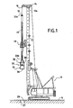
- the equipment comprises a piling rig 10 provided with a vertical mast 12.
- the upper end 12a of the mast is equipped with two pulleys 14, 16 for a cable 18.
- the mast 12 also forms a vertical guide for a movable rotary drive box 20.
- the rotary drive box 20 can be moved along the whole length of the mast 12.
- the equipment further comprises a set of driving rods or Kelly bar 22.
- the Kelly bar consists of a plurality of steel tubes which are locked one to the other.
- the upper end 22a of the Kelly bar is secured to an end of the cable 18. As a result, the up and down vertical movement of the Kelly bar is controlled by the cable.
- the Kelly bar 22 passes through the rotary drive box 20 and the box 20 applies a rotative torque to the Kelly bar 22. However, the Kelly bar can be vertically moved with respect to the box 20.
- the lower end 22b of the Kelly bar or of the driving rods is connected to a threading equipment 30 or displaceable assembly.
- the threading equipment 30 preferably comprises an upper section 32 and a lower section 34 which are interconnected.
- the upper section 32 will be described in greater detail hereinafter.
- the lower section 34 is in the form of a cylindrical container 36 for catching the clay or soil cuttings as they fall from the upper section 32 which consists of a cutting device 38 adapted to cut a thread or helical slot in the internal wall 37 of a previously bored pile shaft 39.
- the equipment further comprises speed transducers (not shown) to measure the vertical displacement speed and the rotational speed of the driving rods 22.
- the lower section 34 consists of a cylindrical container 36 having a cylindrical lateral wall 40, a bottom, 42 and an opened upper end 44.
- the bottom 42 is secured to a rotating control axis 46, the upper end of which is connected by a linking member 48 to the lower end of the driving rods.
- the upper section 32 consists of a threading equipment.
- the threading equipment comprises two cutting tools 52 and 54 diametrically opposed about the vertical control axis 46.
- Each cutting tool is linked to the axis 46 by a control mechanism 56 and 58.
- the control mechanisms are designed so that each cutting tool 52 or 54 can be moved, in a plane substantially perpendicular to the axis 46, between a retracted position shown in figure 3 and an expanded position shown in figure 2. More precisely, when the axis is rotated in the direction of arrow F1, the cutting tools are moved into their expanded position and when the axis 46 is rotated in the direction of arrow F2, the cutting tools are moved into their retracted position.
- the driving rods are rotated in the direction F2 so that the cutting member 50 is maintained in its retracted position.
- the rods 22 are rotated in the direction F1 so that the cutting tools 52 and 54 are moved and maintained in their expanded position.
- the assembly is lifted with controlled vertical and rotational speeds so that the tool 50 cuts in the wall 37 of the bore 39 a thread having the shape of an helical slot.
- the thread has a pitch which is defined by the vertical and rotational speeds. This pitch can be varied along the length of the bored shaft. The thread can extend only along a lower portion of the shaft.
- the assembly 30 is rotated in the direction F2 when the thread is terminated.
- the soil cuttings fall into the cylindrical container 36.
- the thread can be formed in one or several sections depending on the capacity of the container 36. As previously explained, the threading equipment can have no lower section, i.e. no bucket.
- Fig. 6 shows a shaft 39, the wall 37 of which is provided with a thread or helical slot 58.
- the shape of the thread is defined by the shape of the cutting tool 50.
- the threading bucket can be equipped with two diametrically opposed cutting tools. Thus, a double helical slot is obtained.
- the threading equipment is provided with a bucket.
- This equipment is called a threading bucket.
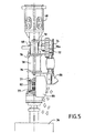
- the threading bucket numbered 60 is provided with means to create a friction force between the threading equipment and the wall of the shaft. This friction force permits the actual movement of the cutting member with respect to the frame of the equipment in its expanded position and its retracted position.
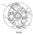
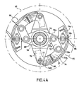
- the cutting device 62 comprises two diametrically disposed cutting systems 64 and 66. These two cutting systems are identical, so only cutting system 64 will be described.
- the cutting system 64 comprises a vertical drive tube 68 which is attached to the lower end 22b of the Kelly bar 22.
- Drive brackets 70 are secured to the drive tube 68.
- Linking levers 72 have a first end 72a which is pivotally mounted on the end 70a of the drive brackets 70.
- the second end 72b of the linking levers 72 is pivotally mounted on the median portion 74a of a cutting frame 74.
- the cutting frame 74 In a horizontal plane, the cutting frame 74 has the shape of an arc of a circle.
- a first end 74b of the cutting frame 74 is pivotally mounted at the end 76a of upper drag bracket 76.
- the upper drag brackets 76 are secured to a drag tube 78 which is mounted around the outside of the drive tube 68.
- the drag tube 78 can rotate around the drive tube 68, thus allowing the drag brackets 76 to rotate relative to the drive brackets 70.
- Lower drag brackets 77 are also secured to the drag tube 78.
- the end 77a of the lower drag brackets 77 is equipped with a drag plate 80.
- the drag plate 80 has the general shape of a portion of cylinder and is mounted on the drag bracket 76 by means of a biasing spring 82.
- the second end 74C of the cutting frame 74 is provided with a tool holder 84 for receiving the cutting tool or cutting teeth 86.
- the cutting tool 86 projects outside the external face 74d of the cutting frame 74.
- the drag plate 80 is disposed below the cutting tool 86.
- the drag plate 80 is positioned so as to be in firm contact with the inner wall 37 of the shaft under the effect of the biasing spring 82 when the threading equipment is introduced into the upper end of the shaft.
- the threading bucket is rotated in a counter-clockwise direction to retract the cutting tools 86, thus allowing it to be removed from the shaft.
- the threading equipment is lifted 800 mm for each rotation, thereby forming a double helix with a pitch of 800 mm and a distance between two threads of 400 mm.
Landscapes
- Engineering & Computer Science (AREA)
- Life Sciences & Earth Sciences (AREA)
- Mining & Mineral Resources (AREA)
- Structural Engineering (AREA)
- General Life Sciences & Earth Sciences (AREA)
- Geology (AREA)
- Paleontology (AREA)
- Civil Engineering (AREA)
- General Engineering & Computer Science (AREA)
- Environmental & Geological Engineering (AREA)
- Physics & Mathematics (AREA)
- Fluid Mechanics (AREA)
- Mechanical Engineering (AREA)
- Geochemistry & Mineralogy (AREA)
- Yarns And Mechanical Finishing Of Yarns Or Ropes (AREA)
- Earth Drilling (AREA)
- External Artificial Organs (AREA)
- Placing Or Removing Of Piles Or Sheet Piles, Or Accessories Thereof (AREA)
- Finish Polishing, Edge Sharpening, And Grinding By Specific Grinding Devices (AREA)
- Perforating, Stamping-Out Or Severing By Means Other Than Cutting (AREA)
- Treatment Of Fiber Materials (AREA)
- Milling Processes (AREA)
Claims (10)
- Gewindeschneideeinrichtung (30) für das Schneiden eines Gewindes in die Innenfläche einer Bohrung (39) umfassend:eine verschiebbare Baugruppe umfassend:einen oberen Abschnitt (32), der Schneidemittel (52, 54) und Betätigungsmittel (56, 58) enthält, um das Schneidemittel aus einer zurückgezogenen Stellung, in der das Schneidemittel innerhalb der Bohrung angeordnet ist, in eine expandierte Stellung zu bewegen, in der das Schneidemittel in die Wand der Bohrung vorsteht, und Mittel (80) zur Erzeugung einer Reibkraft zwischen dem oberen Abschnitt und der Innenfläche (37) der Bohrung;Mittel zur Steuerung der Vertikalverschiebungsgeschwindigkeit der verschiebbaren Baugruppe innerhalb der Bohrung; undMittel zur Steuerung der Rotationsgeschwindigkeit und der Drehrichtung der Baugruppe um ihre vertikale Achse innerhalb der Bohrung, wodurch das Schneidemittel (52, 54) angepaßt ist, mindestens ein Gewinde mit einer gesteuerten Gewindesteigung entlang einer gesteuerten Länge der Bohrung in die Oberfläche der Bohrung zu schneiden, wenn sich das Schneidemittel in seiner expandierten Stellung befindet.
- Gewindeschneideeinrichtung nach Anspruch 1, worin die verschiebbare Baugruppe weiterhin einen mit dem oberen Abschnitt verbundenen unteren Abschnitt (34) umfaßt, wobei der untere Abschnitt einen zylindrischen Behälter bildet.
- Gewindeschneideeinrichtung nach Anspruch 1 oder 2, worin die Mittel zur Steuerung der Verschiebungen der verschiebbaren Baugruppe umfassen:eine Mehrzahl von Antriebsstangen (22), wobei die verschiebbare Baugruppe an das untere Ende der Stangen angeschlossen ist;Mittel für das Rotieren der Stangen mit einer gesteuerten Geschwindigkeit und in einer Richtung im Uhrzeigersinn oder einer Richtung im Gegenuhrzeigersinn; undMittel für vertikales Bewegen der Stangen bei gesteuerter Geschwindigkeit.
- Gewindeschneideeinrichtung nach einem der Ansprüche 1 bis 3, worin die Mittel zum Bewegen des Schneidemittels mechanische Verkettungsmittel (72) umfassen, die ein erstes an die Schneidemittel angeschlossenes Ende und ein zweites kinematisch so an die unteren Stangen angeschlossenes Ende aufweisen, daß sich das Schneidemittel in seiner expandierten Rotation befindet, wenn die Stangen in einer ersten Richtung gedreht werden und in seiner zurückgezogenen Stellung, wenn die Stangen in der zweiten Richtung gedreht werden.
- Gewindeschneideeinrichtung nach einem der Ansprüche 1 bis 4, worin das Schneidemittel zwischen seiner zurückgezogenen und expandierten Stellung innerhalb einer Ebene senkrecht zu der Längsachse der verschiebbaren Baugruppe bewegt wird.
- Gewindeschneideeinrichtung nach einem der Ansprüche 1 bis 5, worin die Mittel zur Erzeugung einer Reibkraft mindestens zwei bewegbare durch zwei Vorspannmittel beaufschlagte Hemmplatten (80) einschließen.
- Gewindeschneideeinrichtung nach Anspruch 4, worin die mechanischen Verkettungsmittel umfassen:- ein an den Stangen befestigtes Antriebsrohr (68);- ein das Antriebsrohr umgebend montiertes Hemmrohr (78);- ein das Schneidemittel tragendes Tragglied (74), das ein erstes an dem Antriebsrohr befestigtes Ende hat, wobei das Schneidemittel an einem von dem ersten Ende unterschiedlichen Platz an dem Tragglied befestigt ist;- ein an dem Antriebsrohr befestigter Antriebsarm (70),- ein Hebelglied (72) mit einem ersten schwenkbar an dem Ende des Arms angebrachten Ende und einem zweiten schwenkbar an dem Tragglied an einem von dem ersten Ende unterschiedlichen Platz angebrachten Ende.
- Gewindeschneideeinrichtung nach Anspruch 7, weiterhin umfassend zwei an dem Hemmrohr (78) befestigte Hemmarme (77) und zwei Hemmplatten (80), wobei jede Hemmplatte an dem Ende eines Hemmarms (77) mittels Vorspannfedern angebracht ist.
- Gewindeschneideeinrichtung nach einem der Ansprüche 1 bis 8, worin das Schneidemittel (52, 54) ein Messer ist, dessen aktives Ende im Vertikalschnitt die Form des Profils des in die Oberfläche der Bohrung zu schneidenden Gewindes hat.
- Gewindeschneideeinrichtung nach einem der Ansprüche 1 bis 9, worin das Schneidemittel (52, 54) zwei diametral gegenüberliegende Schneidekörper umfaßt.
Priority Applications (1)
| Application Number | Priority Date | Filing Date | Title |
|---|---|---|---|
| PL04291004T PL1471187T3 (pl) | 2003-04-22 | 2004-04-15 | Urządzenie gwintujące |
Applications Claiming Priority (2)
| Application Number | Priority Date | Filing Date | Title |
|---|---|---|---|
| GB0309090 | 2003-04-22 | ||
| GB0309090A GB2400869B (en) | 2003-04-22 | 2003-04-22 | Threading equipment |
Publications (2)
| Publication Number | Publication Date |
|---|---|
| EP1471187A1 EP1471187A1 (de) | 2004-10-27 |
| EP1471187B1 true EP1471187B1 (de) | 2006-11-29 |
Family
ID=9957082
Family Applications (1)
| Application Number | Title | Priority Date | Filing Date |
|---|---|---|---|
| EP04291004A Expired - Lifetime EP1471187B1 (de) | 2003-04-22 | 2004-04-15 | Gewindeschneideeinrichtung |
Country Status (7)
| Country | Link |
|---|---|
| EP (1) | EP1471187B1 (de) |
| AT (1) | ATE346988T1 (de) |
| DE (1) | DE602004003418T2 (de) |
| ES (1) | ES2277218T3 (de) |
| GB (1) | GB2400869B (de) |
| PL (1) | PL1471187T3 (de) |
| PT (1) | PT1471187E (de) |
Families Citing this family (5)
| Publication number | Priority date | Publication date | Assignee | Title |
|---|---|---|---|---|
| FR2889241B1 (fr) * | 2005-07-28 | 2013-05-17 | Cie Du Sol | Tariere a ergot mobile |
| EP1748108B1 (de) * | 2005-07-28 | 2010-09-08 | Soletanche Freyssinet | Bohrschnecke |
| FR2940661B1 (fr) * | 2008-12-30 | 2011-01-21 | Cie Du Sol | Machine d'excavation ayant un kelly muni de cavites debouchant sur deux faces |
| IT1394002B1 (it) * | 2009-04-21 | 2012-05-17 | Soilmec Spa | Attrezzatura di scavo e costipazione per la costruzione di pali a vite. |
| JP6427477B2 (ja) * | 2015-09-24 | 2018-11-21 | 前田製管株式会社 | 拡大孔掘削用ヘッド |
Family Cites Families (8)
| Publication number | Priority date | Publication date | Assignee | Title |
|---|---|---|---|---|
| GB240667A (en) * | 1924-11-06 | 1925-10-08 | William Langsdorf | Improvements in ground augers |
| US1916691A (en) * | 1932-03-24 | 1933-07-04 | Raymond Concrete Pile Co | Reamer for earth boring buckets |
| GB2183703A (en) * | 1985-08-22 | 1987-06-10 | Cementation Piling & Found | In situ concrete pile construction and under cutting tool |
| JP2724548B2 (ja) * | 1995-07-10 | 1998-03-09 | 関西電力株式会社 | 2段拡大ヘッド |
| GB9620251D0 (en) * | 1996-09-26 | 1996-11-13 | Cementation Piling & Found | Bearing capacity enhancement for piling applications |
| JPH112085A (ja) * | 1997-04-18 | 1999-01-06 | Nippon Concrete Ind Co Ltd | 掘削装置 |
| JP2000337072A (ja) * | 1999-06-01 | 2000-12-05 | Sanekata Naoya | 地中掘削装置および地中掘削方法 |
| GB2377235A (en) * | 2001-07-17 | 2003-01-08 | Cie Du Sol | Drilling tool |
-
2003
- 2003-04-22 GB GB0309090A patent/GB2400869B/en not_active Expired - Fee Related
-
2004
- 2004-04-15 PT PT04291004T patent/PT1471187E/pt unknown
- 2004-04-15 PL PL04291004T patent/PL1471187T3/pl unknown
- 2004-04-15 AT AT04291004T patent/ATE346988T1/de not_active IP Right Cessation
- 2004-04-15 EP EP04291004A patent/EP1471187B1/de not_active Expired - Lifetime
- 2004-04-15 ES ES04291004T patent/ES2277218T3/es not_active Expired - Lifetime
- 2004-04-15 DE DE602004003418T patent/DE602004003418T2/de not_active Expired - Lifetime
Also Published As
| Publication number | Publication date |
|---|---|
| DE602004003418T2 (de) | 2007-10-04 |
| ATE346988T1 (de) | 2006-12-15 |
| ES2277218T3 (es) | 2007-07-01 |
| PL1471187T3 (pl) | 2007-04-30 |
| EP1471187A1 (de) | 2004-10-27 |
| DE602004003418D1 (de) | 2007-01-11 |
| GB2400869B (en) | 2006-11-15 |
| PT1471187E (pt) | 2007-02-28 |
| GB2400869A (en) | 2004-10-27 |
| GB0309090D0 (en) | 2003-05-28 |
Similar Documents
| Publication | Publication Date | Title |
|---|---|---|
| US7938198B2 (en) | Rotary digging and compression enlarging driller and boring method | |
| JP4505479B2 (ja) | 地中施工杭を作るための掘削装置および方法 | |
| CN109736715B (zh) | 变截面螺旋钻具及变截面钻孔灌注桩的施工方法 | |
| CN109736709B (zh) | 倒伞形扩大头钻机及变径钻孔灌注桩的施工方法 | |
| AU2020333796B2 (en) | Kelly bar arrangement for a drilling apparatus and method for working the ground | |
| US20070023207A1 (en) | Auger with a movable gouge for making a boreholes | |
| EP1471187A1 (de) | Gewindeschneideeinrichtung | |
| US3282356A (en) | Drilling device | |
| KR100865688B1 (ko) | 굴착 장치 | |
| CN117231131A (zh) | 微成孔灌注桩钻孔设备及快速钻孔施工方法 | |
| JP6713621B2 (ja) | 拡大掘削装置および拡大掘削工法 | |
| HK1040538A1 (zh) | 用於在地上形成椿的挖土裝置 | |
| WO1996005402A1 (en) | Direction controllable subsurface borehole tool | |
| HK1071915A (en) | Threading equipment | |
| CN220469781U (zh) | 一种用于成型不同尺寸的矩形桩的成孔设备 | |
| CN114293546B (zh) | 一种穿越溶洞桩基双护筒支护、碎石加固施工方法 | |
| CN117888811A (zh) | 一种矩形桩成孔设备 | |
| CN115461523B (zh) | 工作机械和用于加工土地的方法 | |
| US3598193A (en) | Cutter bits with radially extendable cutter elements | |
| JP2017227067A (ja) | 掘削装置 | |
| KR101578127B1 (ko) | 회동식 굴착직경 조절형 지반천공장치 및 이를 이용한 굴착직경 확장형 지반 천공 공법 | |
| JPH086864Y2 (ja) | 拡底工法用の掘削装置 | |
| CN220791173U (zh) | 一种用于旋挖副孔位成孔的定位装置 | |
| CN115198733B (zh) | 一种钻孔灌注桩施工工艺 | |
| CN120626067A (zh) | 一种实时调整钻杆姿态的桩基施工装置 |
Legal Events
| Date | Code | Title | Description |
|---|---|---|---|
| PUAI | Public reference made under article 153(3) epc to a published international application that has entered the european phase |
Free format text: ORIGINAL CODE: 0009012 |
|
| AK | Designated contracting states |
Kind code of ref document: A1 Designated state(s): AT BE BG CH CY CZ DE DK EE ES FI FR GB GR HU IE IT LI LU MC NL PL PT RO SE SI SK TR |
|
| AX | Request for extension of the european patent |
Extension state: AL HR LT LV MK |
|
| 17P | Request for examination filed |
Effective date: 20050408 |
|
| AKX | Designation fees paid |
Designated state(s): AT BE BG CH CY CZ DE DK EE ES FI FR GB GR HU IE IT LI LU MC NL PL PT RO SE SI SK TR |
|
| REG | Reference to a national code |
Ref country code: HK Ref legal event code: DE Ref document number: 1071915 Country of ref document: HK |
|
| GRAP | Despatch of communication of intention to grant a patent |
Free format text: ORIGINAL CODE: EPIDOSNIGR1 |
|
| GRAS | Grant fee paid |
Free format text: ORIGINAL CODE: EPIDOSNIGR3 |
|
| GRAA | (expected) grant |
Free format text: ORIGINAL CODE: 0009210 |
|
| AK | Designated contracting states |
Kind code of ref document: B1 Designated state(s): AT BE BG CH CY CZ DE DK EE ES FI FR GB GR HU IE IT LI LU MC NL PL PT RO SE SI SK TR |
|
| PG25 | Lapsed in a contracting state [announced via postgrant information from national office to epo] |
Ref country code: AT Free format text: LAPSE BECAUSE OF FAILURE TO SUBMIT A TRANSLATION OF THE DESCRIPTION OR TO PAY THE FEE WITHIN THE PRESCRIBED TIME-LIMIT Effective date: 20061129 Ref country code: CZ Free format text: LAPSE BECAUSE OF FAILURE TO SUBMIT A TRANSLATION OF THE DESCRIPTION OR TO PAY THE FEE WITHIN THE PRESCRIBED TIME-LIMIT Effective date: 20061129 Ref country code: SI Free format text: LAPSE BECAUSE OF FAILURE TO SUBMIT A TRANSLATION OF THE DESCRIPTION OR TO PAY THE FEE WITHIN THE PRESCRIBED TIME-LIMIT Effective date: 20061129 Ref country code: FI Free format text: LAPSE BECAUSE OF FAILURE TO SUBMIT A TRANSLATION OF THE DESCRIPTION OR TO PAY THE FEE WITHIN THE PRESCRIBED TIME-LIMIT Effective date: 20061129 Ref country code: NL Free format text: LAPSE BECAUSE OF FAILURE TO SUBMIT A TRANSLATION OF THE DESCRIPTION OR TO PAY THE FEE WITHIN THE PRESCRIBED TIME-LIMIT Effective date: 20061129 Ref country code: LI Free format text: LAPSE BECAUSE OF FAILURE TO SUBMIT A TRANSLATION OF THE DESCRIPTION OR TO PAY THE FEE WITHIN THE PRESCRIBED TIME-LIMIT Effective date: 20061129 Ref country code: RO Free format text: LAPSE BECAUSE OF FAILURE TO SUBMIT A TRANSLATION OF THE DESCRIPTION OR TO PAY THE FEE WITHIN THE PRESCRIBED TIME-LIMIT Effective date: 20061129 Ref country code: SK Free format text: LAPSE BECAUSE OF FAILURE TO SUBMIT A TRANSLATION OF THE DESCRIPTION OR TO PAY THE FEE WITHIN THE PRESCRIBED TIME-LIMIT Effective date: 20061129 Ref country code: CH Free format text: LAPSE BECAUSE OF FAILURE TO SUBMIT A TRANSLATION OF THE DESCRIPTION OR TO PAY THE FEE WITHIN THE PRESCRIBED TIME-LIMIT Effective date: 20061129 Ref country code: BE Free format text: LAPSE BECAUSE OF FAILURE TO SUBMIT A TRANSLATION OF THE DESCRIPTION OR TO PAY THE FEE WITHIN THE PRESCRIBED TIME-LIMIT Effective date: 20061129 |
|
| REG | Reference to a national code |
Ref country code: GB Ref legal event code: FG4D |
|
| REG | Reference to a national code |
Ref country code: CH Ref legal event code: EP |
|
| REG | Reference to a national code |
Ref country code: IE Ref legal event code: FG4D |
|
| REF | Corresponds to: |
Ref document number: 602004003418 Country of ref document: DE Date of ref document: 20070111 Kind code of ref document: P |
|
| PG25 | Lapsed in a contracting state [announced via postgrant information from national office to epo] |
Ref country code: BG Free format text: LAPSE BECAUSE OF FAILURE TO SUBMIT A TRANSLATION OF THE DESCRIPTION OR TO PAY THE FEE WITHIN THE PRESCRIBED TIME-LIMIT Effective date: 20070228 Ref country code: SE Free format text: LAPSE BECAUSE OF FAILURE TO SUBMIT A TRANSLATION OF THE DESCRIPTION OR TO PAY THE FEE WITHIN THE PRESCRIBED TIME-LIMIT Effective date: 20070228 Ref country code: DK Free format text: LAPSE BECAUSE OF FAILURE TO SUBMIT A TRANSLATION OF THE DESCRIPTION OR TO PAY THE FEE WITHIN THE PRESCRIBED TIME-LIMIT Effective date: 20070228 |
|
| REG | Reference to a national code |
Ref country code: PT Ref legal event code: SC4A Free format text: AVAILABILITY OF NATIONAL TRANSLATION Effective date: 20070209 |
|
| REG | Reference to a national code |
Ref country code: HU Ref legal event code: AG4A Ref document number: E001154 Country of ref document: HU |
|
| PGFP | Annual fee paid to national office [announced via postgrant information from national office to epo] |
Ref country code: HU Payment date: 20070426 Year of fee payment: 4 |
|
| REG | Reference to a national code |
Ref country code: PL Ref legal event code: T3 |
|
| ET | Fr: translation filed | ||
| NLV1 | Nl: lapsed or annulled due to failure to fulfill the requirements of art. 29p and 29m of the patents act | ||
| REG | Reference to a national code |
Ref country code: CH Ref legal event code: PL |
|
| REG | Reference to a national code |
Ref country code: ES Ref legal event code: FG2A Ref document number: 2277218 Country of ref document: ES Kind code of ref document: T3 |
|
| PLBE | No opposition filed within time limit |
Free format text: ORIGINAL CODE: 0009261 |
|
| STAA | Information on the status of an ep patent application or granted ep patent |
Free format text: STATUS: NO OPPOSITION FILED WITHIN TIME LIMIT |
|
| 26N | No opposition filed |
Effective date: 20070830 |
|
| PG25 | Lapsed in a contracting state [announced via postgrant information from national office to epo] |
Ref country code: GR Free format text: LAPSE BECAUSE OF FAILURE TO SUBMIT A TRANSLATION OF THE DESCRIPTION OR TO PAY THE FEE WITHIN THE PRESCRIBED TIME-LIMIT Effective date: 20070301 |
|
| PG25 | Lapsed in a contracting state [announced via postgrant information from national office to epo] |
Ref country code: HU Free format text: LAPSE BECAUSE OF NON-PAYMENT OF DUE FEES Effective date: 20080416 Ref country code: EE Free format text: LAPSE BECAUSE OF FAILURE TO SUBMIT A TRANSLATION OF THE DESCRIPTION OR TO PAY THE FEE WITHIN THE PRESCRIBED TIME-LIMIT Effective date: 20061129 |
|
| PG25 | Lapsed in a contracting state [announced via postgrant information from national office to epo] |
Ref country code: MC Free format text: LAPSE BECAUSE OF NON-PAYMENT OF DUE FEES Effective date: 20070430 |
|
| PG25 | Lapsed in a contracting state [announced via postgrant information from national office to epo] |
Ref country code: CY Free format text: LAPSE BECAUSE OF FAILURE TO SUBMIT A TRANSLATION OF THE DESCRIPTION OR TO PAY THE FEE WITHIN THE PRESCRIBED TIME-LIMIT Effective date: 20061129 Ref country code: LU Free format text: LAPSE BECAUSE OF NON-PAYMENT OF DUE FEES Effective date: 20070415 |
|
| PG25 | Lapsed in a contracting state [announced via postgrant information from national office to epo] |
Ref country code: TR Free format text: LAPSE BECAUSE OF FAILURE TO SUBMIT A TRANSLATION OF THE DESCRIPTION OR TO PAY THE FEE WITHIN THE PRESCRIBED TIME-LIMIT Effective date: 20061129 |
|
| REG | Reference to a national code |
Ref country code: HK Ref legal event code: WD Ref document number: 1071915 Country of ref document: HK |
|
| PGFP | Annual fee paid to national office [announced via postgrant information from national office to epo] |
Ref country code: PT Payment date: 20120319 Year of fee payment: 9 |
|
| REG | Reference to a national code |
Ref country code: PT Ref legal event code: MM4A Free format text: LAPSE DUE TO NON-PAYMENT OF FEES Effective date: 20131015 |
|
| PG25 | Lapsed in a contracting state [announced via postgrant information from national office to epo] |
Ref country code: PT Free format text: LAPSE BECAUSE OF NON-PAYMENT OF DUE FEES Effective date: 20131015 |
|
| REG | Reference to a national code |
Ref country code: FR Ref legal event code: PLFP Year of fee payment: 13 |
|
| REG | Reference to a national code |
Ref country code: FR Ref legal event code: PLFP Year of fee payment: 14 |
|
| REG | Reference to a national code |
Ref country code: FR Ref legal event code: PLFP Year of fee payment: 15 |
|
| PGFP | Annual fee paid to national office [announced via postgrant information from national office to epo] |
Ref country code: PL Payment date: 20200318 Year of fee payment: 17 |
|
| PGFP | Annual fee paid to national office [announced via postgrant information from national office to epo] |
Ref country code: ES Payment date: 20200504 Year of fee payment: 17 |
|
| PGFP | Annual fee paid to national office [announced via postgrant information from national office to epo] |
Ref country code: IT Payment date: 20200318 Year of fee payment: 17 |
|
| PGFP | Annual fee paid to national office [announced via postgrant information from national office to epo] |
Ref country code: IE Payment date: 20220323 Year of fee payment: 19 Ref country code: GB Payment date: 20220323 Year of fee payment: 19 |
|
| PGFP | Annual fee paid to national office [announced via postgrant information from national office to epo] |
Ref country code: FR Payment date: 20220323 Year of fee payment: 19 |
|
| REG | Reference to a national code |
Ref country code: ES Ref legal event code: FD2A Effective date: 20220701 |
|
| PG25 | Lapsed in a contracting state [announced via postgrant information from national office to epo] |
Ref country code: ES Free format text: LAPSE BECAUSE OF NON-PAYMENT OF DUE FEES Effective date: 20210416 |
|
| PGFP | Annual fee paid to national office [announced via postgrant information from national office to epo] |
Ref country code: DE Payment date: 20220322 Year of fee payment: 19 |
|
| PG25 | Lapsed in a contracting state [announced via postgrant information from national office to epo] |
Ref country code: PL Free format text: LAPSE BECAUSE OF NON-PAYMENT OF DUE FEES Effective date: 20210415 |
|
| PG25 | Lapsed in a contracting state [announced via postgrant information from national office to epo] |
Ref country code: IT Free format text: LAPSE BECAUSE OF NON-PAYMENT OF DUE FEES Effective date: 20200415 |
|
| REG | Reference to a national code |
Ref country code: DE Ref legal event code: R119 Ref document number: 602004003418 Country of ref document: DE |
|
| GBPC | Gb: european patent ceased through non-payment of renewal fee |
Effective date: 20230415 |
|
| PG25 | Lapsed in a contracting state [announced via postgrant information from national office to epo] |
Ref country code: GB Free format text: LAPSE BECAUSE OF NON-PAYMENT OF DUE FEES Effective date: 20230415 |
|
| PG25 | Lapsed in a contracting state [announced via postgrant information from national office to epo] |
Ref country code: GB Free format text: LAPSE BECAUSE OF NON-PAYMENT OF DUE FEES Effective date: 20230415 Ref country code: FR Free format text: LAPSE BECAUSE OF NON-PAYMENT OF DUE FEES Effective date: 20230430 Ref country code: DE Free format text: LAPSE BECAUSE OF NON-PAYMENT OF DUE FEES Effective date: 20231103 |
|
| REG | Reference to a national code |
Ref country code: IE Ref legal event code: MM4A |
|
| PG25 | Lapsed in a contracting state [announced via postgrant information from national office to epo] |
Ref country code: IE Free format text: LAPSE BECAUSE OF NON-PAYMENT OF DUE FEES Effective date: 20230415 |
|
| PG25 | Lapsed in a contracting state [announced via postgrant information from national office to epo] |
Ref country code: IE Free format text: LAPSE BECAUSE OF NON-PAYMENT OF DUE FEES Effective date: 20230415 |
|
| PG25 | Lapsed in a contracting state [announced via postgrant information from national office to epo] |
Ref country code: IT Free format text: LAPSE BECAUSE OF NON-PAYMENT OF DUE FEES Effective date: 20210415 |