EP1470978B1 - Verfahren und Vorrichtung zur Erkennung eines Fahrzustands - Google Patents
Verfahren und Vorrichtung zur Erkennung eines Fahrzustands Download PDFInfo
- Publication number
- EP1470978B1 EP1470978B1 EP04003778A EP04003778A EP1470978B1 EP 1470978 B1 EP1470978 B1 EP 1470978B1 EP 04003778 A EP04003778 A EP 04003778A EP 04003778 A EP04003778 A EP 04003778A EP 1470978 B1 EP1470978 B1 EP 1470978B1
- Authority
- EP
- European Patent Office
- Prior art keywords
- driving
- driving state
- signal
- states
- state
- Prior art date
- Legal status (The legal status is an assumption and is not a legal conclusion. Google has not performed a legal analysis and makes no representation as to the accuracy of the status listed.)
- Expired - Lifetime
Links
- 238000000034 method Methods 0.000 title claims abstract description 22
- 238000011156 evaluation Methods 0.000 claims description 23
- 230000001133 acceleration Effects 0.000 claims description 8
- 230000000007 visual effect Effects 0.000 claims description 3
- 238000001914 filtration Methods 0.000 claims description 2
- 238000005096 rolling process Methods 0.000 claims 6
- 230000008569 process Effects 0.000 abstract description 4
- 238000012360 testing method Methods 0.000 description 38
- 230000005484 gravity Effects 0.000 description 4
- 230000001105 regulatory effect Effects 0.000 description 4
- 230000003247 decreasing effect Effects 0.000 description 3
- 238000001514 detection method Methods 0.000 description 3
- 238000010586 diagram Methods 0.000 description 3
- 239000011159 matrix material Substances 0.000 description 3
- 230000007774 longterm Effects 0.000 description 2
- 230000006978 adaptation Effects 0.000 description 1
- 230000003044 adaptive effect Effects 0.000 description 1
- 230000008901 benefit Effects 0.000 description 1
- 230000008859 change Effects 0.000 description 1
- 238000013016 damping Methods 0.000 description 1
- 230000001419 dependent effect Effects 0.000 description 1
- 238000005259 measurement Methods 0.000 description 1
- 238000012545 processing Methods 0.000 description 1
- 230000009467 reduction Effects 0.000 description 1
- 230000004044 response Effects 0.000 description 1
Images
Classifications
-
- B—PERFORMING OPERATIONS; TRANSPORTING
- B60—VEHICLES IN GENERAL
- B60T—VEHICLE BRAKE CONTROL SYSTEMS OR PARTS THEREOF; BRAKE CONTROL SYSTEMS OR PARTS THEREOF, IN GENERAL; ARRANGEMENT OF BRAKING ELEMENTS ON VEHICLES IN GENERAL; PORTABLE DEVICES FOR PREVENTING UNWANTED MOVEMENT OF VEHICLES; VEHICLE MODIFICATIONS TO FACILITATE COOLING OF BRAKES
- B60T8/00—Arrangements for adjusting wheel-braking force to meet varying vehicular or ground-surface conditions, e.g. limiting or varying distribution of braking force
- B60T8/17—Using electrical or electronic regulation means to control braking
- B60T8/172—Determining control parameters used in the regulation, e.g. by calculations involving measured or detected parameters
-
- B—PERFORMING OPERATIONS; TRANSPORTING
- B60—VEHICLES IN GENERAL
- B60T—VEHICLE BRAKE CONTROL SYSTEMS OR PARTS THEREOF; BRAKE CONTROL SYSTEMS OR PARTS THEREOF, IN GENERAL; ARRANGEMENT OF BRAKING ELEMENTS ON VEHICLES IN GENERAL; PORTABLE DEVICES FOR PREVENTING UNWANTED MOVEMENT OF VEHICLES; VEHICLE MODIFICATIONS TO FACILITATE COOLING OF BRAKES
- B60T2230/00—Monitoring, detecting special vehicle behaviour; Counteracting thereof
- B60T2230/03—Overturn, rollover
-
- B—PERFORMING OPERATIONS; TRANSPORTING
- B60—VEHICLES IN GENERAL
- B60W—CONJOINT CONTROL OF VEHICLE SUB-UNITS OF DIFFERENT TYPE OR DIFFERENT FUNCTION; CONTROL SYSTEMS SPECIALLY ADAPTED FOR HYBRID VEHICLES; ROAD VEHICLE DRIVE CONTROL SYSTEMS FOR PURPOSES NOT RELATED TO THE CONTROL OF A PARTICULAR SUB-UNIT
- B60W50/00—Details of control systems for road vehicle drive control not related to the control of a particular sub-unit, e.g. process diagnostic or vehicle driver interfaces
- B60W2050/0001—Details of the control system
- B60W2050/0043—Signal treatments, identification of variables or parameters, parameter estimation or state estimation
- B60W2050/0052—Filtering, filters
- B60W2050/0054—Cut-off filters, retarders, delaying means, dead zones, threshold values or cut-off frequency
- B60W2050/0056—Low-pass filters
-
- B—PERFORMING OPERATIONS; TRANSPORTING
- B60—VEHICLES IN GENERAL
- B60W—CONJOINT CONTROL OF VEHICLE SUB-UNITS OF DIFFERENT TYPE OR DIFFERENT FUNCTION; CONTROL SYSTEMS SPECIALLY ADAPTED FOR HYBRID VEHICLES; ROAD VEHICLE DRIVE CONTROL SYSTEMS FOR PURPOSES NOT RELATED TO THE CONTROL OF A PARTICULAR SUB-UNIT
- B60W50/00—Details of control systems for road vehicle drive control not related to the control of a particular sub-unit, e.g. process diagnostic or vehicle driver interfaces
- B60W50/08—Interaction between the driver and the control system
- B60W50/14—Means for informing the driver, warning the driver or prompting a driver intervention
- B60W2050/143—Alarm means
-
- B—PERFORMING OPERATIONS; TRANSPORTING
- B60—VEHICLES IN GENERAL
- B60W—CONJOINT CONTROL OF VEHICLE SUB-UNITS OF DIFFERENT TYPE OR DIFFERENT FUNCTION; CONTROL SYSTEMS SPECIALLY ADAPTED FOR HYBRID VEHICLES; ROAD VEHICLE DRIVE CONTROL SYSTEMS FOR PURPOSES NOT RELATED TO THE CONTROL OF A PARTICULAR SUB-UNIT
- B60W2520/00—Input parameters relating to overall vehicle dynamics
- B60W2520/18—Roll
-
- B—PERFORMING OPERATIONS; TRANSPORTING
- B60—VEHICLES IN GENERAL
- B60W—CONJOINT CONTROL OF VEHICLE SUB-UNITS OF DIFFERENT TYPE OR DIFFERENT FUNCTION; CONTROL SYSTEMS SPECIALLY ADAPTED FOR HYBRID VEHICLES; ROAD VEHICLE DRIVE CONTROL SYSTEMS FOR PURPOSES NOT RELATED TO THE CONTROL OF A PARTICULAR SUB-UNIT
- B60W2530/00—Input parameters relating to vehicle conditions or values, not covered by groups B60W2510/00 or B60W2520/00
-
- B—PERFORMING OPERATIONS; TRANSPORTING
- B60—VEHICLES IN GENERAL
- B60W—CONJOINT CONTROL OF VEHICLE SUB-UNITS OF DIFFERENT TYPE OR DIFFERENT FUNCTION; CONTROL SYSTEMS SPECIALLY ADAPTED FOR HYBRID VEHICLES; ROAD VEHICLE DRIVE CONTROL SYSTEMS FOR PURPOSES NOT RELATED TO THE CONTROL OF A PARTICULAR SUB-UNIT
- B60W2552/00—Input parameters relating to infrastructure
- B60W2552/15—Road slope, i.e. the inclination of a road segment in the longitudinal direction
-
- B—PERFORMING OPERATIONS; TRANSPORTING
- B60—VEHICLES IN GENERAL
- B60W—CONJOINT CONTROL OF VEHICLE SUB-UNITS OF DIFFERENT TYPE OR DIFFERENT FUNCTION; CONTROL SYSTEMS SPECIALLY ADAPTED FOR HYBRID VEHICLES; ROAD VEHICLE DRIVE CONTROL SYSTEMS FOR PURPOSES NOT RELATED TO THE CONTROL OF A PARTICULAR SUB-UNIT
- B60W2552/00—Input parameters relating to infrastructure
- B60W2552/20—Road profile, i.e. the change in elevation or curvature of a plurality of continuous road segments
-
- B—PERFORMING OPERATIONS; TRANSPORTING
- B60—VEHICLES IN GENERAL
- B60W—CONJOINT CONTROL OF VEHICLE SUB-UNITS OF DIFFERENT TYPE OR DIFFERENT FUNCTION; CONTROL SYSTEMS SPECIALLY ADAPTED FOR HYBRID VEHICLES; ROAD VEHICLE DRIVE CONTROL SYSTEMS FOR PURPOSES NOT RELATED TO THE CONTROL OF A PARTICULAR SUB-UNIT
- B60W2552/00—Input parameters relating to infrastructure
- B60W2552/30—Road curve radius
-
- B—PERFORMING OPERATIONS; TRANSPORTING
- B60—VEHICLES IN GENERAL
- B60W—CONJOINT CONTROL OF VEHICLE SUB-UNITS OF DIFFERENT TYPE OR DIFFERENT FUNCTION; CONTROL SYSTEMS SPECIALLY ADAPTED FOR HYBRID VEHICLES; ROAD VEHICLE DRIVE CONTROL SYSTEMS FOR PURPOSES NOT RELATED TO THE CONTROL OF A PARTICULAR SUB-UNIT
- B60W2710/00—Output or target parameters relating to a particular sub-units
- B60W2710/18—Braking system
-
- B—PERFORMING OPERATIONS; TRANSPORTING
- B60—VEHICLES IN GENERAL
- B60W—CONJOINT CONTROL OF VEHICLE SUB-UNITS OF DIFFERENT TYPE OR DIFFERENT FUNCTION; CONTROL SYSTEMS SPECIALLY ADAPTED FOR HYBRID VEHICLES; ROAD VEHICLE DRIVE CONTROL SYSTEMS FOR PURPOSES NOT RELATED TO THE CONTROL OF A PARTICULAR SUB-UNIT
- B60W30/00—Purposes of road vehicle drive control systems not related to the control of a particular sub-unit, e.g. of systems using conjoint control of vehicle sub-units
- B60W30/02—Control of vehicle driving stability
- B60W30/04—Control of vehicle driving stability related to roll-over prevention
Definitions
- the invention relates to a method for detecting a driving state, in particular of a motor vehicle.
- the invention is the object of the invention to provide an improved method for detecting a driving condition.
- the present invention enables recognition of a driving condition from a set of driving conditions. This can be done so that each driving condition is assigned a test criterion. For detecting a driving condition, first several driving parameters are detected. Based on these driving parameters, the test criteria of the driving conditions are then evaluated.
- test criteria thus proceeds in chronological order from the test criterion of the most dangerous driving state to that of the least dangerous driving state.
- This sequence of data processing ensures that particularly dangerous driving conditions with the highest priority, i. H. especially fast, can be detected.
- the amount of driving conditions includes a third driving condition: (iii) tipping tendency when driving on a slope or when standing on a slope.
- the driving state "tilting tendency in dynamic driving maneuver” is classified as the most dangerous, the driving state “quasi-static circular drive” as the second most dangerous and the driving state “driving on a slope or standing on a slope” as the least dangerous driving condition.
- this classification test criteria are assigned to the different driving conditions, which are evaluated continuously on the basis of several driving parameters.
- test criterion of the driving condition "tendency to tilt during dynamic maneuvering" is fulfilled by the driving parameters. If this is not the case, then the test criterion for the second most dangerous driving condition and then the test criterion for the least dangerous driving condition is evaluated.
- a driving parameter for the detection of a driving condition for example, the roll angle, the roll angular velocity, lateral acceleration, yaw rate, the steering angle and / or wheel contact forces can be used, which are detected by corresponding sensors.
- the roll angle is obtained by evaluating the signals from height sensors which measure the distance between a wheel axle and a vehicle body. From the roll angle, the roll angular velocity can be determined, for example, by filtering the roll angle signal through two different low-pass filters and subtracting the filter outputs from one another. If one of the filters is a large time constant filter, i. H. a so-called long-term filter, and the other filter is a filter with a small time constant, d. H. a so-called short-term filter, the output signal is proportional to the roll angular velocity.
- a threshold value is assigned to a first driving condition as the checking criterion and a second driving condition is assigned to a second driving condition as the checking criterion, the first driving condition being more dangerous than the second driving condition, and the first threshold value being selected such that it already has been reached can be used without exceeding the second threshold; For example, therefore, the first threshold is selected smaller than the second threshold.
- a warning signal is output upon detection of one of the driving states. This can be done via a Display device in the vehicle cockpit to warn the driver accordingly.
- the warning signal can be output as a visual or as a haptic and / or acoustic signal.
- a signal is output to a vehicle control and / or regulating system.
- this signal preferably indicates the detected driving state, so that the control and / or regulating system can react appropriately. If, for example, a driving state with a tendency to tilt is detected, the tilting tendency can be counteracted by an automatic braking and / or a steering intervention and / or further measures.
- an ABS, ESP, active steering adjustment and / or engine management system come into question as control and / or regulating systems which are addressed for this purpose.
- the application of the method according to the invention is particularly in vehicles with high center of gravity, such. B. in vans, vans or off-road vehicles advantageous because such vehicles with high center of gravity in dynamic driving maneuvers, d. H. can tilt during sudden changes of direction or during cornering or roundabout.
- a risk of tipping can be detected in good time to quickly take appropriate countermeasures such.
- an additional braking torque and / or an adaptation of the damper characteristic As a reduction of the engine torque, an additional braking torque and / or an adaptation of the damper characteristic.
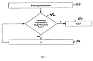
- FIG. 1 shows a flowchart for detecting a driving state.
- one or more driving parameters are detected. For example, the roll angle, the roll speed, lateral acceleration, yaw rate, the steering angle and / or the wheel contact forces of a motor vehicle are detected.
- Each of these driving states of the set F is assigned a test criterion P i . If a test criterion P i is met by the detected driving parameters, this means that the driving condition F i is present.
- the driving conditions are classified with regard to their dangerousness and sorted accordingly.
- the most dangerous driving condition is the driving condition F 1 ;
- the least dangerous driving state is the driving state F N , wherein the intermediate driving states F 2 to F N-1 have a decreasing dangerousness in this order.
- the test in step 102 is carried out such that it is first checked whether the most dangerous driving state F 1 is present by evaluating the corresponding test criterion P 1 by means of the driving parameters detected in step 100. If the test criterion P 1 by the Driving parameters met, it means that the driving condition F1 is present. Subsequently, a signal is output in step 104.
- the signal 104 may be a warning signal for the driver, which is output, for example, via an indication via the instrument panel of the motor vehicle.
- the index i is incremented in the step 106 in order then to evaluate the test criterion P 2 for the less dangerous driving state F 2 in the step 102.
- This process is performed until either one of the driving conditions has been detected and a signal has been issued in step 104, or until it has been determined that none of the driving conditions is in the set F.
- the signal output in step 104 includes an indication of the detected driving condition. If, for example, the most dangerous driving condition has been detected, a haptic signal and an acoustic warning signal for the driver are simultaneously output. In a less dangerous driving condition, for example, only an audible warning signal is output and in the least dangerous driving condition only a visual warning signal.
- the signal output in step 104 can be input to a control and / or regulation system of the vehicle, which can then react in accordance with the detected driving state in order to reduce the danger. For example, an automatic deceleration can be made to reduce a tendency to tilt the vehicle.
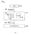
- the safety system 200 has one or more sensors 202 for detecting one or more of the driving parameters 204 of a motor vehicle.
- the driving parameter or parameters 204 are input to an evaluation module 206.
- the evaluation module 206 has a memory area 208 in which the test criteria P 1 , P 2 ,..., P N are stored in this order. After the initialization of the security system 200, a pointer 210 points to the address in the memory area 208 in which the test criterion P 1 for the most dangerous driving state F 1 is stored.
- the evaluation module 206 also has a memory area 212 in which a program is stored.
- the program in the memory area 212 serves to evaluate the test criteria P i stored in the memory area 208 with the aid of the driving parameters 204.
- the program of the memory area 212 If one of the test criteria P i is met by the driving parameters 204, ie the corresponding driving state F i has been detected, the program of the memory area 212 generates a corresponding signal 214, which is input to a vehicle dynamics control and / or regulation system of the vehicle. On the basis of the signal 214, the control and / or regulation system 216 can then, for example, change a chassis parameter of the motor vehicle in order, for example, to reduce a tilting tendency of the vehicle. Alternatively or additionally, a warning signal for the driver of the vehicle can also be generated on the basis of the signal 214.
- sensor 202 continuously outputs driving parameters 204 detected by measurement and / or by signal evaluation.
- the program 212 first checks whether the driving parameter or parameters 204 satisfy the test criterion P 1 . If this is the case, the signal 214 is output. If the opposite is true, the pointer 210 is incremented to point to the adjacent address range in the memory 208 in which the next Test criterion P 2 is stored. This test criterion P 2 is then checked on the basis of the driving parameters 204, etc.
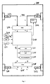
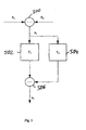
- FIG. 3 shows a schematic illustration of a motor vehicle 300.
- the motor vehicle 300 has a sensor 304 on the left side of the front axle 302 and a sensor 306 on the right side. Accordingly, the motor vehicle 300 has a left sensor 310 and a right sensor on its rear axle 308 312.
- the sensors 304, 306, and 310, 312 may be height sensors that measure the distance of each axis from the body of the motor vehicle 300.
- the signals S 1 and S 2 output by the sensors 304 and 306 are input to a filter module 314.
- the filter module 314 With the aid of the signals S 1 and S 2 , the filter module 314 generates the signals x 1 and x 2 , the signal x 1, for example, proportional to a roll angle of the motor vehicle 300 on the front axle 302 and the signal x 2 proportional to the roll angular velocity at the front axle 302 is.
- the signals S 3 and S 4 of the sensors 310 and 312 are input to a filter module 316 which outputs the signals x 3 and x 4 .
- the signal x 3 is proportional to a roll angle at the rear axle 308 and the signal x 4 is proportional to the roll angular velocity at the rear axle 308.
- the signals x 1 , x 2 , x 3 and x 4 are input to an evaluation module 318, which has basically the same structure as the evaluation module 206 of FIG. 2.
- a sensor 320 for measuring a transverse acceleration of the motor vehicle 300 may be present.
- the sensor 320 inputs a signal a Q , which is proportional to the measured lateral acceleration, into the evaluation module 318.
- a sensor 322 for detecting a yaw rate, ie the rotational speed about the vertical axis of the vehicle, may be present. The yaw rates determined by the sensor 322 are input to the evaluation module 318, where they can be converted into lateral acceleration data based on a vehicle model.
- a sensor 324 may be provided for detecting a steering angle.
- the sensor 324 outputs a signal proportional to the steering angle to the evaluation module 318.
- the signal G i is input to, for example, an ABS system 326, an ESP system 328, and / or an engine management system 330. Alternatively or additionally, the signal G i can also be input to an adaptive chassis control system which, for example, adjusts the damping characteristics of the motor vehicle 300 in response to the signal G 1.
- a corresponding warning signal can be output via the display 332 in order to warn the driver of the motor vehicle 300.
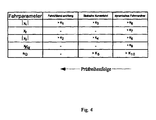
- FIG. 4 shows in tabular form a decision matrix of the evaluation module 318.
- the decision matrix is mapped, for example, in the program logic of the evaluation module 318 (compare the program in the memory area 212 of FIG. 2).
- test criterion P 1 for the driving condition F 1 is as follows:
- the magnitude of the signal x 1 is above the threshold K 6
- the signal x 2 is above the threshold K 7
- the magnitude of the signal x 3 is above the threshold K 8
- the signal x 4 is above the threshold K 9
- the signal a Q is above the threshold K 10 .
- test criterion P 1 is satisfied and the driving condition F 1 is present.
- test criterion P 2 for the driving condition F 2 is as follows:
- the magnitude of the signal x 1 is above the threshold value K 3
- the magnitude of the signal x 3 is above the threshold value K 4
- the signal a Q is above the threshold value K 5 .
- the signals x 2 and x 4 are not included in the test criterion P 2 .
- the threshold values K 3 , K 4 and K 5 can be selected to be greater than the corresponding threshold values K 6 , K 8 and K 10 .
- test criterion P 3 for the least dangerous driving condition F 3 is as follows:
- the magnitude of the signal x 1 is above the threshold value K 1 and the magnitude of the signal x 3 is above the threshold value K 2 . Since the driving state F 3 is less critical than the driving state F 2 , the threshold values K 1 and K 2 can again be selected above the corresponding threshold values K 3 and K 4 , ie it is K 1 > K 3 > K 6 and K 2 > K 4 > K 8 and also K 5 > K 10 .
- the evaluation criterion P 1 is first evaluated by the evaluation module in order to check whether the driving condition F 1 is present. If this is not the case, then the test of the test criterion P 2 follows, and if this too is not fulfilled, finally the evaluation of the test criterion P 1 . This results in a test sequence after decreasing danger of the driving conditions. If, in this test sequence, one of the driving states F i is detected, then a corresponding signal G i is emitted, as explained above with reference to FIG. 3, inter alia.
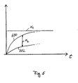
- FIG. 5 shows an example of the implementation of the filter module 314.
- the filter module has a subtracter 500 which subtracts the signals S 1 and S 2 from one another. The result of this subtraction is the signal x 1 , which is proportional to the roll angle at the front axle 302 (see FIG. 3).
- the signal x 1 is input to the two filters 502 and 504.
- the filter 502 is a so-called long-term filter, ie a low-pass filter with a relatively large time constant T 1
- the filter 504 is a so-called short-time filter, ie a low-pass filter with a relatively short time constant T 2 .
- the time constant T 1 is in the range of 1 second to 50 seconds
- the time constant T 2 is in the range of 10 to 100 milliseconds.
- the output signals of the filters 502 and 504 are subtracted from each other by the subtractor 506 so as to obtain the signal x 2 , which is approximately proportional to the roll angular velocity, ie the derivative of the signal x 1 .
- FIG. 6 shows the time profile of the signal x 1 and the signals 600 and 602, wherein the signal 600 is the output signal of the filter 504 and the signal 602 is the output signal of the filter 502.
- the difference of these signals is the signal x 2 , which due to the different time constants T 1 and T 2 of the filters 502 and 504 is approximately the derivative of the signal x 1 .
Landscapes
- Engineering & Computer Science (AREA)
- Transportation (AREA)
- Mechanical Engineering (AREA)
- Control Of Driving Devices And Active Controlling Of Vehicle (AREA)
- Auxiliary Drives, Propulsion Controls, And Safety Devices (AREA)
- Regulating Braking Force (AREA)
- Forklifts And Lifting Vehicles (AREA)
Applications Claiming Priority (2)
| Application Number | Priority Date | Filing Date | Title |
|---|---|---|---|
| DE10318111A DE10318111A1 (de) | 2003-04-22 | 2003-04-22 | Verfahren und Vorrichtung zur Erkennung eines Fahrzustands |
| DE10318111 | 2003-04-22 |
Publications (2)
| Publication Number | Publication Date |
|---|---|
| EP1470978A1 EP1470978A1 (de) | 2004-10-27 |
| EP1470978B1 true EP1470978B1 (de) | 2007-10-31 |
Family
ID=32946390
Family Applications (1)
| Application Number | Title | Priority Date | Filing Date |
|---|---|---|---|
| EP04003778A Expired - Lifetime EP1470978B1 (de) | 2003-04-22 | 2004-02-19 | Verfahren und Vorrichtung zur Erkennung eines Fahrzustands |
Country Status (5)
| Country | Link |
|---|---|
| US (1) | US7209818B2 (enExample) |
| EP (1) | EP1470978B1 (enExample) |
| JP (1) | JP2004323009A (enExample) |
| AT (1) | ATE376950T1 (enExample) |
| DE (2) | DE10318111A1 (enExample) |
Families Citing this family (13)
| Publication number | Priority date | Publication date | Assignee | Title |
|---|---|---|---|---|
| JP4391785B2 (ja) | 2003-09-30 | 2009-12-24 | 三菱ふそうトラック・バス株式会社 | 車両のロールオーバ抑制制御装置 |
| JP4228864B2 (ja) | 2003-09-30 | 2009-02-25 | 三菱ふそうトラック・バス株式会社 | 車両のロールオーバ抑制制御装置 |
| JP2005271818A (ja) | 2004-03-25 | 2005-10-06 | Mitsubishi Fuso Truck & Bus Corp | 車両のロールオーバ抑制制御装置 |
| US20060100632A1 (en) * | 2004-11-09 | 2006-05-11 | Fell Barry M | Apparatus and method for shaping a mammalian joint surface |
| DE102005054127A1 (de) * | 2005-11-14 | 2007-05-16 | Bosch Gmbh Robert | Verfahren und Vorrichtung zur Ansteuerung von Personenschutzmitteln bei einem Überrollvorgang |
| DE102006040443B4 (de) * | 2006-08-29 | 2011-01-27 | Zf Lenksysteme Gmbh | Verfahren zum Betrieb eines elektronisch geregelten Servolenksystems |
| DE102006061249A1 (de) * | 2006-12-22 | 2008-06-26 | Siemens Ag | Verfahren und Vorrichtung zum Ermitteln einer Reibkennzahl |
| DE102009000080B4 (de) | 2009-01-08 | 2019-03-07 | Robert Bosch Gmbh | Verfahren und Steuergerät zum Erkennen eines Fahrzustands eines Fahrzeugs |
| KR101077094B1 (ko) | 2009-04-17 | 2011-10-26 | (주)이노시뮬레이션 | 차량 위험운전 판단 시스템 및 방법 |
| DE102010036638A1 (de) * | 2010-07-27 | 2012-02-02 | Dr. Ing. H.C. F. Porsche Aktiengesellschaft | Verfahren zum Bestimmen des Reibwerts bei einem Fahrzeug |
| DE102011010714A1 (de) * | 2011-02-09 | 2012-08-09 | GM Global Technology Operations LLC (n. d. Gesetzen des Staates Delaware) | Kraftfahrzeug mit adaptivem Chassis |
| US10017142B2 (en) * | 2016-09-12 | 2018-07-10 | Ford Global Technologies, Llc | Filtration of acoustic contaminate from vehicle safety sensors |
| US11686767B2 (en) * | 2017-11-02 | 2023-06-27 | Intel Corporation | System, apparatus and method for functional testing of one or more fabrics of a processor |
Family Cites Families (28)
| Publication number | Priority date | Publication date | Assignee | Title |
|---|---|---|---|---|
| US5189619A (en) * | 1989-09-05 | 1993-02-23 | Toyota Jidosha Kabushiki Kaisha | AI-based adaptive vehicle control system |
| JPH10119743A (ja) * | 1996-10-23 | 1998-05-12 | Aisin Seiki Co Ltd | 車両の運動制御装置 |
| DE19744725A1 (de) * | 1997-10-10 | 1999-04-15 | Itt Mfg Enterprises Inc | Verfahren zum Bestimmen von Zustandsgrößen eines Kraftfahrzeuges |
| US6366844B1 (en) * | 1997-12-16 | 2002-04-02 | Continental Teves Ag & Co., Ohg | Method and device for limiting transversal acceleration in a motor vehicle |
| DE19830189A1 (de) * | 1998-05-14 | 1999-11-18 | Continental Teves Ag & Co Ohg | Verfahren zur Erhöhung der Kippstabilität eines Fahrzeugs |
| DE19802041A1 (de) * | 1998-01-21 | 1999-07-22 | Bosch Gmbh Robert | Verfahren und Vorrichtung zur Stabilisierung eines Fahrzeuges im Sinne einer Umkippvermeidung |
| JP3252797B2 (ja) * | 1998-06-19 | 2002-02-04 | トヨタ自動車株式会社 | ロールオーバー判別方法 |
| DE19829361A1 (de) * | 1998-07-01 | 2000-01-05 | Bayerische Motoren Werke Ag | Verfahren und Vorrichtung zur Verbesserung der Kippsicherheit von Kraftfahrzeugen |
| WO2000003887A1 (de) * | 1998-07-16 | 2000-01-27 | Continental Teves Ag & Co. Ohg | Verfahren und einrichtung zum erfassen der gefahr des umkippens eines kraftfahrzeugs |
| DE19856303A1 (de) * | 1998-07-16 | 2000-01-27 | Continental Teves Ag & Co Ohg | Verfahren und Einrichtung zum Erfassen der Gefahr des Umkippens eines Kraftfahrzeugs |
| DE19904219B4 (de) * | 1998-07-16 | 2013-03-28 | Continental Teves Ag & Co. Ohg | Verfahren und Vorrichtung zum Ermitteln von kritischen Fahrzuständen bei im Fahrbetrieb befindlichen Fahrzeugen |
| DE19904216A1 (de) * | 1998-07-17 | 2000-01-20 | Continental Teves Ag & Co Ohg | Verfahren und Vorrichtung zum Bestimmen und Erkennen der Kippgefahr eines Fahrzeuges |
| WO2000003900A1 (de) * | 1998-07-17 | 2000-01-27 | Continental Teves Ag & Co. Ohg | Verfahren und vorrichtung zum bestimmen und erkennen der kippgefahr eines fahrzeuges |
| DE19918597C2 (de) * | 1999-04-23 | 2001-03-08 | Deutsch Zentr Luft & Raumfahrt | Verfahren zur Reduktion der Kippgefahr von Straßenfahrzeugen |
| JP2000357299A (ja) * | 1999-06-16 | 2000-12-26 | Honda Motor Co Ltd | 車両の走行安全装置 |
| DE10039108B4 (de) * | 1999-08-13 | 2012-03-22 | Continental Teves Ag & Co. Ohg | Verfahren und Vorrichtung zum Bestimmen von Fahrzeugzustandsgrößen |
| US6263261B1 (en) * | 1999-12-21 | 2001-07-17 | Ford Global Technologies, Inc. | Roll over stability control for an automotive vehicle |
| DE10003739C2 (de) * | 2000-01-28 | 2002-12-05 | Daimler Chrysler Ag | Verfahren und System zur Identifikation von Systemparametern in Fahrzeugen |
| DE10103629B4 (de) * | 2000-04-28 | 2016-07-28 | Continental Teves Ag & Co. Ohg | Verfahren zur Regelung der Fahrstabilität eines Fahrzeugs |
| WO2001083277A1 (de) * | 2000-04-28 | 2001-11-08 | Continental Teves Ag & Co. Ohg | Verfahren zur regelung der fahrstabilität eines fahrzeugs |
| US6498976B1 (en) * | 2000-10-30 | 2002-12-24 | Freightliner Llc | Vehicle operator advisor system and method |
| JP3518509B2 (ja) * | 2000-12-28 | 2004-04-12 | トヨタ自動車株式会社 | ロールオーバ判定装置 |
| DE10065724A1 (de) * | 2000-12-29 | 2002-07-04 | Bosch Gmbh Robert | Bremsregelsystem zur Stabilisierung der Bewegung eines Nutzfahrzeugs |
| US6799092B2 (en) * | 2001-02-21 | 2004-09-28 | Ford Global Technologies, Llc | Rollover stability control for an automotive vehicle using rear wheel steering and brake control |
| JP2002274214A (ja) * | 2001-03-22 | 2002-09-25 | Nissan Diesel Motor Co Ltd | 車両のロールオーバ防止装置 |
| JP3608527B2 (ja) * | 2001-05-15 | 2005-01-12 | 株式会社豊田中央研究所 | 周辺状況表示装置 |
| DE10133409A1 (de) * | 2001-07-13 | 2003-01-30 | Lucas Automotive Gmbh | Fahrzeugbremssystem |
| DE10135020B4 (de) * | 2001-07-18 | 2005-03-03 | Robert Bosch Gmbh | Verfahren und Vorrichtung zur Erkennung und Behebung einer Umkippgefahr |
-
2003
- 2003-04-22 DE DE10318111A patent/DE10318111A1/de not_active Withdrawn
-
2004
- 2004-02-19 DE DE502004005346T patent/DE502004005346D1/de not_active Expired - Lifetime
- 2004-02-19 EP EP04003778A patent/EP1470978B1/de not_active Expired - Lifetime
- 2004-02-19 AT AT04003778T patent/ATE376950T1/de not_active IP Right Cessation
- 2004-04-21 JP JP2004125530A patent/JP2004323009A/ja active Pending
- 2004-04-22 US US10/829,323 patent/US7209818B2/en not_active Expired - Fee Related
Also Published As
| Publication number | Publication date |
|---|---|
| ATE376950T1 (de) | 2007-11-15 |
| JP2004323009A (ja) | 2004-11-18 |
| EP1470978A1 (de) | 2004-10-27 |
| DE10318111A1 (de) | 2004-11-11 |
| US7209818B2 (en) | 2007-04-24 |
| US20040216020A1 (en) | 2004-10-28 |
| DE502004005346D1 (de) | 2007-12-13 |
Similar Documents
| Publication | Publication Date | Title |
|---|---|---|
| EP0954460B1 (de) | Verfahren und vorrichtung zur erkennung einer kipptendenz eines fahrzeuges | |
| EP1412237B1 (de) | Verfahren und vorrichtung zur erkennung und behebung einer umkippgefahr | |
| EP0975491B1 (de) | Verfahren und vorrichtung zur erkennung einer kipptendenz eines fahrzeuges | |
| DE3850150T2 (de) | Gierkontrolleinrichtung für ein Fahrzeug. | |
| DE102005026456B4 (de) | Verfahren zur Müdigkeitserkennung | |
| DE69328393T2 (de) | Bremssteuerungssystem | |
| EP1470978B1 (de) | Verfahren und Vorrichtung zur Erkennung eines Fahrzustands | |
| WO1999026812A1 (de) | Verfahren und vorrichtung zur erkennung einer kipptendenz eines fahrzeuges | |
| DE102007022184A1 (de) | Fahrerassistenzvorrichtung und Verfahren für dessen Steuerung | |
| DE19949286B4 (de) | Vorrichtung und Verfahren zur Regelung wenigstens einer Fahrzeugbewegungsgrösse | |
| EP0546295B1 (de) | Semiaktives Fahrwerksregelungssystem | |
| DE4419650B4 (de) | Verfahren zum Erkennen eines querdynamisch kritischen oder regelungsbedürftigen Fahrzustandes sowie Vorrichtung hierfür | |
| DE102016204018A1 (de) | Verfahren und Vorrichtung zur Bestimmung der Querneigung einer Fahrbahn | |
| DE102007029605A1 (de) | Verfahren und Vorrichtung zum Beeinflussen der Querdynamik eines Fahrzeugs | |
| EP1646518B1 (de) | An das wankverhalten eines fahrzeugs angepasstes fahrdynamikregelungssystem | |
| DE10354944B4 (de) | Verfahren und Anordnung zur Bestimmung einer Fahrgeschwindigkeit | |
| DE10360732A1 (de) | Vorrichtung und Verfahren zur Kippverhinderung für ein Fahrzeug | |
| DE102004059002A1 (de) | Verfahren zur Anpassung von Eingriffsparametern eines Assistenzsystems eines Fahrzeuges | |
| EP1470941B1 (de) | Verfahren zur Regelung einer Dämpfung | |
| DE102004017634A1 (de) | Vorrichtung zum Ermitteln des Wankwinkels und System sowie Verfahren zur Wankstabilisierung eines Kraftfahrzeuges | |
| DE10353481B4 (de) | Verfahren zum Bestimmen des Reibbeiwertes zwischen Fahrbahn und Reifen eines Kraftfahrzeuges | |
| EP1240038B1 (de) | Verfahren und vorrichtung zur erkennung eines druckverlustes von reifen in kraftfahrzeugen | |
| EP1255653A1 (de) | Verfahren und vorrichtung zur erkennung eines druckverlustes von reifen in kraftfahrzeugen mit plausibilitätsprüfung | |
| DE19846352A1 (de) | Verhaltenssteuersystem für ein Fahrzeug | |
| DE10044114A1 (de) | Verfahren und Vorrichtung zur Erkennung eines Druckverlustes von Reifen in Kraftfahrzeugen mit Plausibilitätsprüfung |
Legal Events
| Date | Code | Title | Description |
|---|---|---|---|
| PUAI | Public reference made under article 153(3) epc to a published international application that has entered the european phase |
Free format text: ORIGINAL CODE: 0009012 |
|
| AK | Designated contracting states |
Kind code of ref document: A1 Designated state(s): AT BE BG CH CY CZ DE DK EE ES FI FR GB GR HU IE IT LI LU MC NL PT RO SE SI SK TR |
|
| AX | Request for extension of the european patent |
Extension state: AL LT LV MK |
|
| 17P | Request for examination filed |
Effective date: 20050427 |
|
| 17Q | First examination report despatched |
Effective date: 20050523 |
|
| AKX | Designation fees paid |
Designated state(s): AT BE BG CH CY CZ DE DK EE ES FI FR GB GR HU IE IT LI LU MC NL PT RO SE SI SK TR |
|
| GRAP | Despatch of communication of intention to grant a patent |
Free format text: ORIGINAL CODE: EPIDOSNIGR1 |
|
| GRAS | Grant fee paid |
Free format text: ORIGINAL CODE: EPIDOSNIGR3 |
|
| GRAA | (expected) grant |
Free format text: ORIGINAL CODE: 0009210 |
|
| AK | Designated contracting states |
Kind code of ref document: B1 Designated state(s): AT BE BG CH CY CZ DE DK EE ES FI FR GB GR HU IE IT LI LU MC NL PT RO SE SI SK TR |
|
| REG | Reference to a national code |
Ref country code: GB Ref legal event code: FG4D Free format text: NOT ENGLISH |
|
| REG | Reference to a national code |
Ref country code: IE Ref legal event code: FG4D Free format text: LANGUAGE OF EP DOCUMENT: GERMAN |
|
| REG | Reference to a national code |
Ref country code: CH Ref legal event code: EP |
|
| REF | Corresponds to: |
Ref document number: 502004005346 Country of ref document: DE Date of ref document: 20071213 Kind code of ref document: P |
|
| NLV1 | Nl: lapsed or annulled due to failure to fulfill the requirements of art. 29p and 29m of the patents act | ||
| PG25 | Lapsed in a contracting state [announced via postgrant information from national office to epo] |
Ref country code: ES Free format text: LAPSE BECAUSE OF FAILURE TO SUBMIT A TRANSLATION OF THE DESCRIPTION OR TO PAY THE FEE WITHIN THE PRESCRIBED TIME-LIMIT Effective date: 20080211 Ref country code: NL Free format text: LAPSE BECAUSE OF FAILURE TO SUBMIT A TRANSLATION OF THE DESCRIPTION OR TO PAY THE FEE WITHIN THE PRESCRIBED TIME-LIMIT Effective date: 20071031 Ref country code: SE Free format text: LAPSE BECAUSE OF FAILURE TO SUBMIT A TRANSLATION OF THE DESCRIPTION OR TO PAY THE FEE WITHIN THE PRESCRIBED TIME-LIMIT Effective date: 20080131 |
|
| GBV | Gb: ep patent (uk) treated as always having been void in accordance with gb section 77(7)/1977 [no translation filed] | ||
| PG25 | Lapsed in a contracting state [announced via postgrant information from national office to epo] |
Ref country code: SI Free format text: LAPSE BECAUSE OF FAILURE TO SUBMIT A TRANSLATION OF THE DESCRIPTION OR TO PAY THE FEE WITHIN THE PRESCRIBED TIME-LIMIT Effective date: 20071031 Ref country code: BG Free format text: LAPSE BECAUSE OF FAILURE TO SUBMIT A TRANSLATION OF THE DESCRIPTION OR TO PAY THE FEE WITHIN THE PRESCRIBED TIME-LIMIT Effective date: 20080131 Ref country code: PT Free format text: LAPSE BECAUSE OF FAILURE TO SUBMIT A TRANSLATION OF THE DESCRIPTION OR TO PAY THE FEE WITHIN THE PRESCRIBED TIME-LIMIT Effective date: 20080331 |
|
| REG | Reference to a national code |
Ref country code: IE Ref legal event code: FD4D |
|
| ET | Fr: translation filed | ||
| PG25 | Lapsed in a contracting state [announced via postgrant information from national office to epo] |
Ref country code: CZ Free format text: LAPSE BECAUSE OF FAILURE TO SUBMIT A TRANSLATION OF THE DESCRIPTION OR TO PAY THE FEE WITHIN THE PRESCRIBED TIME-LIMIT Effective date: 20071031 Ref country code: DK Free format text: LAPSE BECAUSE OF FAILURE TO SUBMIT A TRANSLATION OF THE DESCRIPTION OR TO PAY THE FEE WITHIN THE PRESCRIBED TIME-LIMIT Effective date: 20071031 |
|
| PG25 | Lapsed in a contracting state [announced via postgrant information from national office to epo] |
Ref country code: SK Free format text: LAPSE BECAUSE OF FAILURE TO SUBMIT A TRANSLATION OF THE DESCRIPTION OR TO PAY THE FEE WITHIN THE PRESCRIBED TIME-LIMIT Effective date: 20071031 Ref country code: RO Free format text: LAPSE BECAUSE OF FAILURE TO SUBMIT A TRANSLATION OF THE DESCRIPTION OR TO PAY THE FEE WITHIN THE PRESCRIBED TIME-LIMIT Effective date: 20071031 |
|
| BERE | Be: lapsed |
Owner name: CONTINENTAL A.G. Effective date: 20080228 |
|
| PLBE | No opposition filed within time limit |
Free format text: ORIGINAL CODE: 0009261 |
|
| STAA | Information on the status of an ep patent application or granted ep patent |
Free format text: STATUS: NO OPPOSITION FILED WITHIN TIME LIMIT |
|
| REG | Reference to a national code |
Ref country code: CH Ref legal event code: PL |
|
| 26N | No opposition filed |
Effective date: 20080801 |
|
| PG25 | Lapsed in a contracting state [announced via postgrant information from national office to epo] |
Ref country code: CH Free format text: LAPSE BECAUSE OF NON-PAYMENT OF DUE FEES Effective date: 20080229 Ref country code: LI Free format text: LAPSE BECAUSE OF NON-PAYMENT OF DUE FEES Effective date: 20080229 Ref country code: MC Free format text: LAPSE BECAUSE OF NON-PAYMENT OF DUE FEES Effective date: 20080228 Ref country code: IE Free format text: LAPSE BECAUSE OF FAILURE TO SUBMIT A TRANSLATION OF THE DESCRIPTION OR TO PAY THE FEE WITHIN THE PRESCRIBED TIME-LIMIT Effective date: 20071031 |
|
| PG25 | Lapsed in a contracting state [announced via postgrant information from national office to epo] |
Ref country code: GB Free format text: LAPSE BECAUSE OF FAILURE TO SUBMIT A TRANSLATION OF THE DESCRIPTION OR TO PAY THE FEE WITHIN THE PRESCRIBED TIME-LIMIT Effective date: 20071031 |
|
| PG25 | Lapsed in a contracting state [announced via postgrant information from national office to epo] |
Ref country code: GR Free format text: LAPSE BECAUSE OF FAILURE TO SUBMIT A TRANSLATION OF THE DESCRIPTION OR TO PAY THE FEE WITHIN THE PRESCRIBED TIME-LIMIT Effective date: 20080201 Ref country code: EE Free format text: LAPSE BECAUSE OF FAILURE TO SUBMIT A TRANSLATION OF THE DESCRIPTION OR TO PAY THE FEE WITHIN THE PRESCRIBED TIME-LIMIT Effective date: 20071031 |
|
| PG25 | Lapsed in a contracting state [announced via postgrant information from national office to epo] |
Ref country code: FI Free format text: LAPSE BECAUSE OF FAILURE TO SUBMIT A TRANSLATION OF THE DESCRIPTION OR TO PAY THE FEE WITHIN THE PRESCRIBED TIME-LIMIT Effective date: 20071031 Ref country code: BE Free format text: LAPSE BECAUSE OF NON-PAYMENT OF DUE FEES Effective date: 20080228 |
|
| PG25 | Lapsed in a contracting state [announced via postgrant information from national office to epo] |
Ref country code: AT Free format text: LAPSE BECAUSE OF NON-PAYMENT OF DUE FEES Effective date: 20080219 |
|
| PG25 | Lapsed in a contracting state [announced via postgrant information from national office to epo] |
Ref country code: CY Free format text: LAPSE BECAUSE OF FAILURE TO SUBMIT A TRANSLATION OF THE DESCRIPTION OR TO PAY THE FEE WITHIN THE PRESCRIBED TIME-LIMIT Effective date: 20071031 |
|
| PGFP | Annual fee paid to national office [announced via postgrant information from national office to epo] |
Ref country code: FR Payment date: 20100226 Year of fee payment: 7 |
|
| PG25 | Lapsed in a contracting state [announced via postgrant information from national office to epo] |
Ref country code: LU Free format text: LAPSE BECAUSE OF NON-PAYMENT OF DUE FEES Effective date: 20080219 Ref country code: HU Free format text: LAPSE BECAUSE OF FAILURE TO SUBMIT A TRANSLATION OF THE DESCRIPTION OR TO PAY THE FEE WITHIN THE PRESCRIBED TIME-LIMIT Effective date: 20080501 |
|
| PG25 | Lapsed in a contracting state [announced via postgrant information from national office to epo] |
Ref country code: TR Free format text: LAPSE BECAUSE OF FAILURE TO SUBMIT A TRANSLATION OF THE DESCRIPTION OR TO PAY THE FEE WITHIN THE PRESCRIBED TIME-LIMIT Effective date: 20071031 |
|
| PG25 | Lapsed in a contracting state [announced via postgrant information from national office to epo] |
Ref country code: IT Free format text: LAPSE BECAUSE OF NON-PAYMENT OF DUE FEES Effective date: 20080229 |
|
| REG | Reference to a national code |
Ref country code: DE Ref legal event code: R081 Ref document number: 502004005346 Country of ref document: DE Owner name: CONTINENTAL TEVES AG & CO. OHG, DE Free format text: FORMER OWNER: CONTINENTAL AKTIENGESELLSCHAFT, 30165 HANNOVER, DE Effective date: 20110414 |
|
| REG | Reference to a national code |
Ref country code: FR Ref legal event code: ST Effective date: 20111102 |
|
| PG25 | Lapsed in a contracting state [announced via postgrant information from national office to epo] |
Ref country code: FR Free format text: LAPSE BECAUSE OF NON-PAYMENT OF DUE FEES Effective date: 20110228 |
|
| PGFP | Annual fee paid to national office [announced via postgrant information from national office to epo] |
Ref country code: DE Payment date: 20160229 Year of fee payment: 13 |
|
| REG | Reference to a national code |
Ref country code: DE Ref legal event code: R119 Ref document number: 502004005346 Country of ref document: DE |
|
| PG25 | Lapsed in a contracting state [announced via postgrant information from national office to epo] |
Ref country code: DE Free format text: LAPSE BECAUSE OF NON-PAYMENT OF DUE FEES Effective date: 20170901 |