EP1470960A1 - Ensemble de barres de toit pour un véhicule automobile - Google Patents
Ensemble de barres de toit pour un véhicule automobile Download PDFInfo
- Publication number
- EP1470960A1 EP1470960A1 EP04290878A EP04290878A EP1470960A1 EP 1470960 A1 EP1470960 A1 EP 1470960A1 EP 04290878 A EP04290878 A EP 04290878A EP 04290878 A EP04290878 A EP 04290878A EP 1470960 A1 EP1470960 A1 EP 1470960A1
- Authority
- EP
- European Patent Office
- Prior art keywords
- roof
- central part
- housing
- rack assembly
- roof rack
- Prior art date
- Legal status (The legal status is an assumption and is not a legal conclusion. Google has not performed a legal analysis and makes no representation as to the accuracy of the status listed.)
- Withdrawn
Links
- 230000000295 complement effect Effects 0.000 claims description 4
- 239000000969 carrier Substances 0.000 abstract 2
- BASFCYQUMIYNBI-UHFFFAOYSA-N platinum Chemical compound [Pt] BASFCYQUMIYNBI-UHFFFAOYSA-N 0.000 description 3
Images

Classifications
-
- B—PERFORMING OPERATIONS; TRANSPORTING
- B60—VEHICLES IN GENERAL
- B60R—VEHICLES, VEHICLE FITTINGS, OR VEHICLE PARTS, NOT OTHERWISE PROVIDED FOR
- B60R9/00—Supplementary fittings on vehicle exterior for carrying loads, e.g. luggage, sports gear or the like
- B60R9/04—Carriers associated with vehicle roof
- B60R9/045—Carriers being adjustable or transformable, e.g. expansible, collapsible
Definitions
- the present invention relates to a set of roof bars for a motor vehicle.
- roof bars intended to be mounted on top of a roof of a motor vehicle and which include two roof bars with a central part and, at each end, a part forming a fixing foot on the roof.
- Some motor vehicles are fitted with roof racks longitudinal extending parallel to the longitudinal axis and these roof bars are permanently mounted to support transverse elements for fixing, for example, a gallery, a travel safe or others accessories.
- the transverse elements are removable and are fix with clips, screws and nuts to the longitudinal roof bars. As a result, they take a long time to set up and take up space in the vehicle or in a storage location when not in use.
- the object of the invention is to propose a set of roof bars which avoids the disadvantages previously mentioned and which offers for the user a multitude of adjustment positions depending on the loads to carry.
- the invention therefore relates to a set of roof bars for a motor vehicle comprising two roof bars comprising a part central and, at each end, a part forming a fixing foot on a roof of the vehicle in a position parallel to the longitudinal axis of this vehicle, characterized in that the central part of each roof bar supports a removable and movable element between a first position integrated in the corresponding central part and after turning a quarter turn one second position extending transversely between the roof bars perpendicular to the longitudinal axis of the vehicle, said elements forming, in the second position, a flat surface.
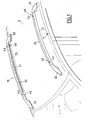
- Fig. 1 there is shown schematically a set of roof bars designated by the general reference 10 and which is intended to be mounted on a roof 2 of a motor vehicle 1.
- the roof bar assembly 10 comprises two roof bars, 20 and 30 respectively, intended to be fixed in a position parallel to the longitudinal axis of the motor vehicle.
- Each roof bar 20 and 30 has a curved longitudinal profile to integrate with the general shape of the pavilion of the vehicle.
- the first roof bar 20 has a central part 21 and, at each end, a portion 22 forming a mounting base on the roof 2.
- the second roof bar 30 has a central portion 31 and, at each end, a part 32 forming a mounting base on the roof 2.
- each roof bar 20 and 30 can comprise a middle support foot on said pavilion 2.
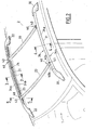
- the central part 21 of the roof bar 20 supports an element 23 removable and movable between a first position integrated in the part central 21 (Fig. 1) and, after turning a quarter turn, a second position extending transversely between the roof bars 20 and 30 perpendicularly to the longitudinal axis of the vehicle (Fig. 2).
- the central part 31 of the roof bar 30 also supports a element 33 which can be dismantled and moved between a first position integrated in this central part 31 (Fig. 1) and after pivoting a quarter of a turn second position extending transversely between the roof bars 20 and 30 perpendicular to the longitudinal axis of the vehicle (Fig. 2).
- the central part 21 of the roof bar 20 is provided with a housing 24 of complementary shape to the element 23.
- This housing 24 has a cross section in the shape of an "L" having a longitudinal outer edge 24a and a bottom 24b provided with a groove longitudinal 25.
- the central part 31 of the roof bar 30 includes a housing 34 ( Figures 2 and 4) of complementary shape to the element 33.
- This housing 34 has an "L" shaped cross section with an outer edge 34a longitudinal and a bottom 34b provided with a longitudinal groove 35.
- the elements 23 and 33 are movable by sliding on the central parts 21 and 31 of the roof bars 20 and 30 so as to adjust the spacing between these elements 23 and 33 as a function of the load transported.
- each element 23 and 33 is provided with each of its ends of a plate designated as a whole by the reference 40 which allows the attachment of each element 23 and 33 on the central parts 21 and 31 in the first and second positions as well as the sliding of these items 23 and 33.
- FIG. 5 we will describe a plate 40 at one end, for example of element 23, the plate 40 at the other end of element 23 as well as the plate of the two ends of element 33 being identical.
- the plate 40 has a first port 40 a and a second port 40 b extending perpendicular to the first port 40 a and offset longitudinally with respect to that -this, as shown in Figure 2.
- the plate 40 is fixed by a connecting member 41 which is formed by a nut 42 disposed in the groove 25 of the housing 24 and by a screw 43 vertically passing through the plate 40 through the orifice 40 a or 40 b and intended to cooperate with the nut 42 to block the element 23 in the desired position or to allow the sliding of this element 23 as a function of the tightening of the screw 43 with the nut 42.
- item 23 is disposed in the housing 21 of the roof bar 20 and the element 33 is placed in the housing 31 of the roof bar 30, a screw 43 being screwed into a nut 42 at each plate 40 through the orifice 40b.
- the user loosens the screw 43 of each plate 40, then places each element 23 and 33 transversely relative to the roof bars 20 and 30 by rotating it a quarter of a turn. Then, he introduces a screw 43 into the orifice 40 a of each plate 40 and gradually screws it into the corresponding nut 42.
- the user Before tightening the screws 43 of the plates 40, the user has the possibility of adjusting the spacing between elements 23 and 33 by sliding the nuts 42 in the grooves 25 and 35 of the central parts 21 and 31 of the bars roof 20 and 30 in the desired position. The user tightens the screws 43 of each plates 40 so as to fix the elements 23 and 33 on the connecting bars 20 and 30.
- each housing 24 and 34 of the central part 21 and 31 of the roof bars 20 and 30 may include means stopping the sliding of the plates 40 on said bottoms so as to limit the reconciliation of elements 23 and 33.
- These means consist for example with punctures 45 or tabs obtained by cutting (Fig. 5) and arranged in said background.
- the elements 23 and 33 form a flat loading surface.
- the set of roof bars according to the invention therefore makes it possible to ability to convert two roof bars easily and by simple means longitudinal in two transverse roof bars for transporting loads of varying lengths.
Landscapes
- Engineering & Computer Science (AREA)
- Mechanical Engineering (AREA)
- Fittings On The Vehicle Exterior For Carrying Loads, And Devices For Holding Or Mounting Articles (AREA)
Abstract
Description
- les éléments sont déplaçables, dans la seconde position, par coulissement sur les parties centrales pour régler l'écartement en fonction de la charge transportée,
- la partie centrale de chaque barre de toit comporte un logement de forme complémentaire à l'élément correspondant,
- le logement de la partie centrale de chaque barre de toit présente une section transversale en forme de "L" comportant un bord extérieur longitudinal et un fond,
- le fond de chaque logement comporte une rainure longitudinale,
- chaque élément comporte, à chacune de ses extrémités, une platine munie de deux orifices s'étendant perpendiculairement l'un par rapport à l'autre et reliée à la partie centrale de chaque barre de toit par un organe de liaison,
- l'organe de liaison est formé par un écrou disposé dans la rainure du logement correspondant et par une vis traversant l'un des orifices de la platine de l'élément et destinée à coopérer avec ledit écrou,
- le fond de chaque logement comporte une butée de limitation du coulissement de la platine de l'élément correspondant.
- la Fig. 1 est une vue schématique en perspective d'un ensemble de barres de toit, conforme à l'invention, pour un véhicule automobile,
- la Fig. 2 est une vue schématique en perspective des barres de toit de la Fig. 1 en position d'utilisation,
- la Fig. 3 est une vue schématique en coupe selon la ligne 3-3 de la Fig. 2,
- la Fig. 4 est une vue schématique en coupe selon la ligne 4-4 de la Fig. 2,
- la Fig. 5 est une vue schématique en coupe selon la ligne 5-5 de la Fig. 2.
Claims (8)
- Ensemble de barres de toit pour un véhicule automobile comprenant deux barres de toit (20, 30) comportant une partie centrale (21, 31) et, à chaque extrémité, une partie (22, 32) formant pied de fixation sur un pavillon (2) du véhicule dans une position parallèle à l'axe longitudinale de ce véhicule, caractérisé en ce que la partie centrale (21, 31) de chaque barre de toit (20, 30) supporte un élément (23, 33) démontable et déplaçable entre une première position intégrée dans la partie centrale (21, 31) correspondante et après pivotement d'un quart de tour une seconde position s'étendant transversalement entre les barres de toit (20, 30) perpendiculairement à l'axe longitudinal du véhicule, lesdits éléments (23, 33) formant dans la seconde position, une surface plane.
- Ensemble de barres de toit selon la revendication 1, caractérisé en ce que, dans la seconde position, les éléments (23, 33) sont déplaçables par coulissement sur les parties centrales (21, 31) pour régler l'écartement en fonction de la charge transportée.
- Ensemble de barres de toit selon les revendications 1 et 2, caractérisé en ce que la partie centrale (21, 31) de chaque barre de toit (20, 30) comporte un logement (24, 34) de forme complémentaire à l'élément (23, 33) correspondant.
- Ensemble de barres de toit selon la revendication 3, caractérisé en ce que le logement (24, 34) de la partie centrale (21, 31) de chaque barre de toit (20, 30) présente une section transversale en forme de "L" comportant un bord extérieur (24a, 34a) longitudinal et un fond (24b, 34b).
- Ensemble de barres de toit selon la revendication 3 ou 4, caractérisé en ce que le fond (24b, 34b) de chaque logement (24, 34) comporte une rainure (25, 35) longitudinale.
- Ensemble de barres de toit selon l'une quelconque des revendications précédentes, caractérisé en ce que chaque élément (23, 33) comporte, à chacune de ses extrémités, une platine (40) munie de deux orifices (40a, 40b) s'étendant perpendiculairement l'un par rapport à l'autre et reliée à la partie centrale (21, 31) par un organe de liaison (41).
- Ensemble de barres de toit selon la revendication 6, caractérisé en ce que l'organe de liaison (41) est formé par un écrou (42) disposé dans la rainure (25, 35) du logement (24, 34) correspondant et par une vis (43) traversant l'un des orifices (40a, 40b) de la platine (40) de l'élément (23, 33) et destinée à coopérer avec ledit écrou (42).
- Ensemble de barres de toit selon l'une quelconque des revendications précédentes, caractérisé en ce que le fond (24b, 34b) de chaque logement (24, 34) comporte une butée (45) de limitation du coulissement de chaque platine (40) de l'élément (23, 33) correspondant.
Applications Claiming Priority (2)
| Application Number | Priority Date | Filing Date | Title |
|---|---|---|---|
| FR0304984 | 2003-04-23 | ||
| FR0304984A FR2854112B1 (fr) | 2003-04-23 | 2003-04-23 | Ensemble de barres de toit pour un vehicule automobile |
Publications (1)
| Publication Number | Publication Date |
|---|---|
| EP1470960A1 true EP1470960A1 (fr) | 2004-10-27 |
Family
ID=32947366
Family Applications (1)
| Application Number | Title | Priority Date | Filing Date |
|---|---|---|---|
| EP04290878A Withdrawn EP1470960A1 (fr) | 2003-04-23 | 2004-04-02 | Ensemble de barres de toit pour un véhicule automobile |
Country Status (2)
| Country | Link |
|---|---|
| EP (1) | EP1470960A1 (fr) |
| FR (1) | FR2854112B1 (fr) |
Cited By (8)
| Publication number | Priority date | Publication date | Assignee | Title |
|---|---|---|---|---|
| GB2414219A (en) * | 2004-05-19 | 2005-11-23 | Jac Products Inc | Vehicle article carrier |
| FR2912971A1 (fr) * | 2007-02-28 | 2008-08-29 | Renault Sas | Dispositif de barres de toit pour vehicule automobile. |
| US8096454B2 (en) | 2008-10-01 | 2012-01-17 | Jac Products, Inc. | System and method for vehicle article carrier having stowable cross bars |
| US8424733B2 (en) * | 2010-04-02 | 2013-04-23 | GM Global Technology Operations LLC | Roof rack bows with mechanism for automatic extension and retraction |
| US8528799B2 (en) | 2008-10-01 | 2013-09-10 | Jac Products, Inc. | System and method for vehicle article carrier having stowable cross bars |
| US10160393B2 (en) | 2016-12-13 | 2018-12-25 | Jac Products, Inc. | Vehicle article carrier system having stretch rails with stowable cross bars |
| US11046254B2 (en) * | 2017-04-25 | 2021-06-29 | Novares France | Device for raising roof bars |
| EP4177112A1 (fr) * | 2021-11-04 | 2023-05-10 | Jac Products, Inc. | Système de porte-bagages avec barres transversales escamotables et dissimulables |
Citations (14)
| Publication number | Priority date | Publication date | Assignee | Title |
|---|---|---|---|---|
| DE3814799A1 (de) * | 1987-05-12 | 1988-11-24 | Volkswagen Ag | Dachtraegersystem fuer ein fahrzeug |
| WO1991008929A1 (fr) * | 1989-12-11 | 1991-06-27 | Industri Ab Thule | Porte-charge |
| FR2661378A1 (fr) * | 1990-04-27 | 1991-10-31 | Peugeot | Porte-bagages pour vehicule automobile. |
| FR2699475A1 (fr) * | 1992-12-18 | 1994-06-24 | Chausson Ingenierie | Dispositif de barres de toit pour véhicule automobile. |
| US5340007A (en) * | 1992-05-06 | 1994-08-23 | Farnier & Penin | Motor vehicle roof-rack |
| US5377890A (en) * | 1993-04-24 | 1995-01-03 | Gebr. Happich Gmbh | Roof rack for vehicles |
| DE29504783U1 (de) * | 1995-03-21 | 1995-05-18 | Oris Fahrzeugteile Hans Riehle GmbH, 71696 Möglingen | Dachreling für Kraftwagen |
| DE29508444U1 (de) * | 1995-05-20 | 1995-08-03 | Kessel, Bernhard, 85101 Lenting | Dachgepäckträger für ein Kraftfahrzeug |
| US5511709A (en) * | 1993-06-29 | 1996-04-30 | Happich Fahrzeug-Dachsysteme Gmbh | Roof rack for motor vehicles |
| JPH08301018A (ja) * | 1995-05-08 | 1996-11-19 | Taro Oshiro | 自動車用ルーフキャリヤ |
| JPH1128982A (ja) * | 1997-07-11 | 1999-02-02 | Suzuki Motor Corp | 自動車のルーフキャリア装置 |
| DE19900217A1 (de) * | 1999-01-07 | 2000-07-13 | Ralf Schwarz | Dachreling für Kraftfahrzeuge mit integrierten Querstreben als Lastenträger |
| DE19961746A1 (de) * | 1999-12-21 | 2001-06-28 | Thomas Hoerter | Flexible Dachreling für Kraftfahrzeuge |
| US6286739B1 (en) * | 1999-09-29 | 2001-09-11 | Sportrack Llc | Article carrier with stowing crossrails |
-
2003
- 2003-04-23 FR FR0304984A patent/FR2854112B1/fr not_active Expired - Fee Related
-
2004
- 2004-04-02 EP EP04290878A patent/EP1470960A1/fr not_active Withdrawn
Patent Citations (14)
| Publication number | Priority date | Publication date | Assignee | Title |
|---|---|---|---|---|
| DE3814799A1 (de) * | 1987-05-12 | 1988-11-24 | Volkswagen Ag | Dachtraegersystem fuer ein fahrzeug |
| WO1991008929A1 (fr) * | 1989-12-11 | 1991-06-27 | Industri Ab Thule | Porte-charge |
| FR2661378A1 (fr) * | 1990-04-27 | 1991-10-31 | Peugeot | Porte-bagages pour vehicule automobile. |
| US5340007A (en) * | 1992-05-06 | 1994-08-23 | Farnier & Penin | Motor vehicle roof-rack |
| FR2699475A1 (fr) * | 1992-12-18 | 1994-06-24 | Chausson Ingenierie | Dispositif de barres de toit pour véhicule automobile. |
| US5377890A (en) * | 1993-04-24 | 1995-01-03 | Gebr. Happich Gmbh | Roof rack for vehicles |
| US5511709A (en) * | 1993-06-29 | 1996-04-30 | Happich Fahrzeug-Dachsysteme Gmbh | Roof rack for motor vehicles |
| DE29504783U1 (de) * | 1995-03-21 | 1995-05-18 | Oris Fahrzeugteile Hans Riehle GmbH, 71696 Möglingen | Dachreling für Kraftwagen |
| JPH08301018A (ja) * | 1995-05-08 | 1996-11-19 | Taro Oshiro | 自動車用ルーフキャリヤ |
| DE29508444U1 (de) * | 1995-05-20 | 1995-08-03 | Kessel, Bernhard, 85101 Lenting | Dachgepäckträger für ein Kraftfahrzeug |
| JPH1128982A (ja) * | 1997-07-11 | 1999-02-02 | Suzuki Motor Corp | 自動車のルーフキャリア装置 |
| DE19900217A1 (de) * | 1999-01-07 | 2000-07-13 | Ralf Schwarz | Dachreling für Kraftfahrzeuge mit integrierten Querstreben als Lastenträger |
| US6286739B1 (en) * | 1999-09-29 | 2001-09-11 | Sportrack Llc | Article carrier with stowing crossrails |
| DE19961746A1 (de) * | 1999-12-21 | 2001-06-28 | Thomas Hoerter | Flexible Dachreling für Kraftfahrzeuge |
Non-Patent Citations (2)
| Title |
|---|
| PATENT ABSTRACTS OF JAPAN vol. 1997, no. 03 31 March 1997 (1997-03-31) * |
| PATENT ABSTRACTS OF JAPAN vol. 1999, no. 05 31 May 1999 (1999-05-31) * |
Cited By (12)
| Publication number | Priority date | Publication date | Assignee | Title |
|---|---|---|---|---|
| US7090103B2 (en) * | 2002-10-24 | 2006-08-15 | Jac Products, Inc. | Vehicle article carrier having stowable cross bars |
| US7448523B2 (en) | 2002-10-24 | 2008-11-11 | Jac Products, Inc. | Vehicle article carrier having stowable cross bars |
| GB2414219A (en) * | 2004-05-19 | 2005-11-23 | Jac Products Inc | Vehicle article carrier |
| GB2414219B (en) * | 2004-05-19 | 2007-09-19 | Jac Products Inc | Article carrier |
| FR2912971A1 (fr) * | 2007-02-28 | 2008-08-29 | Renault Sas | Dispositif de barres de toit pour vehicule automobile. |
| US8096454B2 (en) | 2008-10-01 | 2012-01-17 | Jac Products, Inc. | System and method for vehicle article carrier having stowable cross bars |
| US8528799B2 (en) | 2008-10-01 | 2013-09-10 | Jac Products, Inc. | System and method for vehicle article carrier having stowable cross bars |
| US8424733B2 (en) * | 2010-04-02 | 2013-04-23 | GM Global Technology Operations LLC | Roof rack bows with mechanism for automatic extension and retraction |
| US10160393B2 (en) | 2016-12-13 | 2018-12-25 | Jac Products, Inc. | Vehicle article carrier system having stretch rails with stowable cross bars |
| US11046254B2 (en) * | 2017-04-25 | 2021-06-29 | Novares France | Device for raising roof bars |
| EP4177112A1 (fr) * | 2021-11-04 | 2023-05-10 | Jac Products, Inc. | Système de porte-bagages avec barres transversales escamotables et dissimulables |
| US11912240B2 (en) | 2021-11-04 | 2024-02-27 | Jac Products, Inc. | Vehicle article carrier rack system with stowable, concealable cross bars |
Also Published As
| Publication number | Publication date |
|---|---|
| FR2854112B1 (fr) | 2006-07-14 |
| FR2854112A1 (fr) | 2004-10-29 |
Similar Documents
| Publication | Publication Date | Title |
|---|---|---|
| US5520316A (en) | Storage rack for automobile trunks | |
| FR2776111A1 (fr) | Appui d'epaule reglable pour violons ou instruments analogues | |
| FR2882797A1 (fr) | Attache adaptee a etre fixee dans une cavite de contour predetermine | |
| FR2808483A1 (fr) | Dispositif de reglage motorise pour siege de vehicule | |
| WO2005007449A1 (fr) | Bloc projecteur pour vehicule automobile, et vehicule corresppondant | |
| EP1195181A1 (fr) | Perfectionnement pour dispositif de retenue d'une chaussure sur une planche de glisse sur neige du type surf | |
| FR2854112A1 (fr) | Ensemble de barres de toit pour un vehicule automobile | |
| FR2661378A1 (fr) | Porte-bagages pour vehicule automobile. | |
| FR2658775A1 (fr) | Dispositif de fixation d'une colonne de direction sur la carrosserie d'un vehicule automobile. | |
| FR2769567A1 (fr) | Dispositif de fixation d'une facade avant a la structure avant d'un vehicule automobile | |
| FR2761651A1 (fr) | Dispositif de fixation d'un pare-chocs sur la caisse d'un vehicule automobile | |
| EP1108452A1 (fr) | Dispositif de liasion entre une fixation de chaussure et une planche de glisse | |
| FR2807377A1 (fr) | Systeme de fixation d'une colonne de direction pour un vehicule automobile | |
| EP0703371B1 (fr) | Système de fixation d'un ensemble sur une colonne, notamment pour la fixation d'un ensemble de commutation électrique sur une colonne de direction de véhicule automobile | |
| EP1376807A1 (fr) | Dispositif de fixation rapide d'un conduit de cheminement de câbles à une paroi | |
| EP2792581B1 (fr) | Structure démontable de support d'éléments de carrosserie de véhicule automobile | |
| FR3098472A1 (fr) | Ensemble de barres de toit et d’un agencement de coffre d’un véhicule automobile | |
| EP1396383B1 (fr) | Cache-bagages pour véhicule automobile | |
| FR2796900A1 (fr) | Combinaison d'un element fixe et d'un organe d'arrimage de charges sur un vehicule | |
| FR2567085A1 (fr) | Dispositif pour fixer des objets a une paroi et fourgonnette comportant des cloisons interieures fixees au moyen de tels dispositifs | |
| FR2796535A1 (fr) | Dispositif de support d'etageres reglable en hauteur a creneaux | |
| FR2863245A1 (fr) | Systeme de fixation de roue de secours | |
| FR3033345A1 (fr) | Bac, ensemble comprenant un tel bac et procede d'installation d'un tel ensemble sur une paroi | |
| FR2880317A1 (fr) | Dispositif de fixation pour accessoire de portage | |
| FR3098475A1 (fr) | Planche de bord de vehicule agencee pour maintenir des objets mobiles |
Legal Events
| Date | Code | Title | Description |
|---|---|---|---|
| PUAI | Public reference made under article 153(3) epc to a published international application that has entered the european phase |
Free format text: ORIGINAL CODE: 0009012 |
|
| AK | Designated contracting states |
Kind code of ref document: A1 Designated state(s): AT BE BG CH CY CZ DE DK EE ES FI FR GB GR HU IE IT LI LU MC NL PL PT RO SE SI SK TR |
|
| AX | Request for extension of the european patent |
Extension state: AL HR LT LV MK |
|
| 17P | Request for examination filed |
Effective date: 20050405 |
|
| AKX | Designation fees paid |
Designated state(s): AT BE BG CH CY CZ DE DK EE ES FI FR GB GR HU IE IT LI LU MC NL PL PT RO SE SI SK TR |
|
| 17Q | First examination report despatched |
Effective date: 20090318 |
|
| GRAP | Despatch of communication of intention to grant a patent |
Free format text: ORIGINAL CODE: EPIDOSNIGR1 |
|
| STAA | Information on the status of an ep patent application or granted ep patent |
Free format text: STATUS: THE APPLICATION IS DEEMED TO BE WITHDRAWN |
|
| 18D | Application deemed to be withdrawn |
Effective date: 20121002 |