EP1470958B1 - Surveillance d'un espace libre pour véhicules à moteur - Google Patents
Surveillance d'un espace libre pour véhicules à moteur Download PDFInfo
- Publication number
- EP1470958B1 EP1470958B1 EP04007890A EP04007890A EP1470958B1 EP 1470958 B1 EP1470958 B1 EP 1470958B1 EP 04007890 A EP04007890 A EP 04007890A EP 04007890 A EP04007890 A EP 04007890A EP 1470958 B1 EP1470958 B1 EP 1470958B1
- Authority
- EP
- European Patent Office
- Prior art keywords
- vehicle
- image data
- driver
- free space
- image
- Prior art date
- Legal status (The legal status is an assumption and is not a legal conclusion. Google has not performed a legal analysis and makes no representation as to the accuracy of the status listed.)
- Expired - Lifetime
Links
- 238000012544 monitoring process Methods 0.000 title claims description 8
- 238000012545 processing Methods 0.000 claims description 27
- 230000033001 locomotion Effects 0.000 claims description 25
- 230000003287 optical effect Effects 0.000 claims description 24
- 238000000034 method Methods 0.000 claims description 17
- 238000004891 communication Methods 0.000 claims description 3
- 238000004364 calculation method Methods 0.000 claims description 2
- 238000003672 processing method Methods 0.000 claims 2
- 230000003139 buffering effect Effects 0.000 claims 1
- 238000001514 detection method Methods 0.000 claims 1
- 238000001454 recorded image Methods 0.000 claims 1
- 239000013598 vector Substances 0.000 description 13
- 230000009466 transformation Effects 0.000 description 10
- 230000004907 flux Effects 0.000 description 5
- 230000008901 benefit Effects 0.000 description 4
- 238000006243 chemical reaction Methods 0.000 description 4
- 230000006870 function Effects 0.000 description 4
- 238000003384 imaging method Methods 0.000 description 4
- 235000004522 Pentaglottis sempervirens Nutrition 0.000 description 3
- 230000000007 visual effect Effects 0.000 description 3
- 240000004050 Pentaglottis sempervirens Species 0.000 description 2
- 230000006399 behavior Effects 0.000 description 2
- 238000004422 calculation algorithm Methods 0.000 description 2
- 230000006835 compression Effects 0.000 description 2
- 238000007906 compression Methods 0.000 description 2
- 238000011156 evaluation Methods 0.000 description 2
- 230000003993 interaction Effects 0.000 description 2
- 238000013507 mapping Methods 0.000 description 2
- 239000000463 material Substances 0.000 description 2
- 230000008859 change Effects 0.000 description 1
- 239000003086 colorant Substances 0.000 description 1
- 238000012937 correction Methods 0.000 description 1
- 230000001419 dependent effect Effects 0.000 description 1
- 238000009795 derivation Methods 0.000 description 1
- 238000013461 design Methods 0.000 description 1
- 238000011161 development Methods 0.000 description 1
- 230000018109 developmental process Effects 0.000 description 1
- 230000000694 effects Effects 0.000 description 1
- 230000007613 environmental effect Effects 0.000 description 1
- 230000035939 shock Effects 0.000 description 1
- 230000002123 temporal effect Effects 0.000 description 1
- 238000000844 transformation Methods 0.000 description 1
- 238000011179 visual inspection Methods 0.000 description 1
Images


Classifications
-
- B—PERFORMING OPERATIONS; TRANSPORTING
- B60—VEHICLES IN GENERAL
- B60Q—ARRANGEMENT OF SIGNALLING OR LIGHTING DEVICES, THE MOUNTING OR SUPPORTING THEREOF OR CIRCUITS THEREFOR, FOR VEHICLES IN GENERAL
- B60Q9/00—Arrangement or adaptation of signal devices not provided for in one of main groups B60Q1/00 - B60Q7/00, e.g. haptic signalling
- B60Q9/002—Arrangement or adaptation of signal devices not provided for in one of main groups B60Q1/00 - B60Q7/00, e.g. haptic signalling for parking purposes, e.g. for warning the driver that his vehicle has contacted or is about to contact an obstacle
- B60Q9/004—Arrangement or adaptation of signal devices not provided for in one of main groups B60Q1/00 - B60Q7/00, e.g. haptic signalling for parking purposes, e.g. for warning the driver that his vehicle has contacted or is about to contact an obstacle using wave sensors
- B60Q9/005—Arrangement or adaptation of signal devices not provided for in one of main groups B60Q1/00 - B60Q7/00, e.g. haptic signalling for parking purposes, e.g. for warning the driver that his vehicle has contacted or is about to contact an obstacle using wave sensors using a video camera
-
- B—PERFORMING OPERATIONS; TRANSPORTING
- B60—VEHICLES IN GENERAL
- B60R—VEHICLES, VEHICLE FITTINGS, OR VEHICLE PARTS, NOT OTHERWISE PROVIDED FOR
- B60R1/00—Optical viewing arrangements; Real-time viewing arrangements for drivers or passengers using optical image capturing systems, e.g. cameras or video systems specially adapted for use in or on vehicles
- B60R1/20—Real-time viewing arrangements for drivers or passengers using optical image capturing systems, e.g. cameras or video systems specially adapted for use in or on vehicles
- B60R1/22—Real-time viewing arrangements for drivers or passengers using optical image capturing systems, e.g. cameras or video systems specially adapted for use in or on vehicles for viewing an area outside the vehicle, e.g. the exterior of the vehicle
- B60R1/23—Real-time viewing arrangements for drivers or passengers using optical image capturing systems, e.g. cameras or video systems specially adapted for use in or on vehicles for viewing an area outside the vehicle, e.g. the exterior of the vehicle with a predetermined field of view
- B60R1/26—Real-time viewing arrangements for drivers or passengers using optical image capturing systems, e.g. cameras or video systems specially adapted for use in or on vehicles for viewing an area outside the vehicle, e.g. the exterior of the vehicle with a predetermined field of view to the rear of the vehicle
-
- B—PERFORMING OPERATIONS; TRANSPORTING
- B62—LAND VEHICLES FOR TRAVELLING OTHERWISE THAN ON RAILS
- B62D—MOTOR VEHICLES; TRAILERS
- B62D15/00—Steering not otherwise provided for
- B62D15/02—Steering position indicators ; Steering position determination; Steering aids
- B62D15/029—Steering assistants using warnings or proposing actions to the driver without influencing the steering system
- B62D15/0295—Steering assistants using warnings or proposing actions to the driver without influencing the steering system by overlaying a vehicle path based on present steering angle over an image without processing that image
-
- B—PERFORMING OPERATIONS; TRANSPORTING
- B60—VEHICLES IN GENERAL
- B60R—VEHICLES, VEHICLE FITTINGS, OR VEHICLE PARTS, NOT OTHERWISE PROVIDED FOR
- B60R2300/00—Details of viewing arrangements using cameras and displays, specially adapted for use in a vehicle
- B60R2300/30—Details of viewing arrangements using cameras and displays, specially adapted for use in a vehicle characterised by the type of image processing
- B60R2300/304—Details of viewing arrangements using cameras and displays, specially adapted for use in a vehicle characterised by the type of image processing using merged images, e.g. merging camera image with stored images
- B60R2300/305—Details of viewing arrangements using cameras and displays, specially adapted for use in a vehicle characterised by the type of image processing using merged images, e.g. merging camera image with stored images merging camera image with lines or icons
-
- B—PERFORMING OPERATIONS; TRANSPORTING
- B60—VEHICLES IN GENERAL
- B60R—VEHICLES, VEHICLE FITTINGS, OR VEHICLE PARTS, NOT OTHERWISE PROVIDED FOR
- B60R2300/00—Details of viewing arrangements using cameras and displays, specially adapted for use in a vehicle
- B60R2300/30—Details of viewing arrangements using cameras and displays, specially adapted for use in a vehicle characterised by the type of image processing
- B60R2300/307—Details of viewing arrangements using cameras and displays, specially adapted for use in a vehicle characterised by the type of image processing virtually distinguishing relevant parts of a scene from the background of the scene
-
- B—PERFORMING OPERATIONS; TRANSPORTING
- B60—VEHICLES IN GENERAL
- B60R—VEHICLES, VEHICLE FITTINGS, OR VEHICLE PARTS, NOT OTHERWISE PROVIDED FOR
- B60R2300/00—Details of viewing arrangements using cameras and displays, specially adapted for use in a vehicle
- B60R2300/60—Details of viewing arrangements using cameras and displays, specially adapted for use in a vehicle characterised by monitoring and displaying vehicle exterior scenes from a transformed perspective
-
- B—PERFORMING OPERATIONS; TRANSPORTING
- B60—VEHICLES IN GENERAL
- B60R—VEHICLES, VEHICLE FITTINGS, OR VEHICLE PARTS, NOT OTHERWISE PROVIDED FOR
- B60R2300/00—Details of viewing arrangements using cameras and displays, specially adapted for use in a vehicle
- B60R2300/80—Details of viewing arrangements using cameras and displays, specially adapted for use in a vehicle characterised by the intended use of the viewing arrangement
- B60R2300/8086—Details of viewing arrangements using cameras and displays, specially adapted for use in a vehicle characterised by the intended use of the viewing arrangement for vehicle path indication
-
- B—PERFORMING OPERATIONS; TRANSPORTING
- B60—VEHICLES IN GENERAL
- B60R—VEHICLES, VEHICLE FITTINGS, OR VEHICLE PARTS, NOT OTHERWISE PROVIDED FOR
- B60R2300/00—Details of viewing arrangements using cameras and displays, specially adapted for use in a vehicle
- B60R2300/80—Details of viewing arrangements using cameras and displays, specially adapted for use in a vehicle characterised by the intended use of the viewing arrangement
- B60R2300/8093—Details of viewing arrangements using cameras and displays, specially adapted for use in a vehicle characterised by the intended use of the viewing arrangement for obstacle warning
Definitions
- the invention relates to a method and a device for monitoring the free space in the direction of travel of a vehicle according to the preamble of patent claims 1, from the document EP 1 065 642 A is known.
- JP 2000-67395 A driver information system is described in which the image data descriptive of the road are superimposed with predicted lanes. In this way it is possible for the driver to better estimate the future behavior of his vehicle.
- the system uses the data from two sensors, which are mounted on the front wheels of the vehicle and thus inform about the direction of travel and driving speed of the vehicle. From the sensor data of the future infrastructure is predicted and superimposed as a line structure of an image of the lane in a display unit.
- a disadvantage of the system is that the predicated lane is superimposed only with the image of the road and the driver no visual pictorial information about objects in the area of the track is displayed.
- the image of the surroundings of the vehicle is detected by a plurality of camera systems and transformed into a bird's-eye view.
- This view is displayed at the position corresponding to the vehicle position, a vehicle representing the vehicle symbol.
- the vehicle symbol is designed in such a way that it integrates harmoniously into the surrounding image in its size relations.
- the image information offered to the driver thus corresponds to a view from a point above the vehicle to its surroundings; that is, the vehicle and its surroundings are presented in a kind of bird's-eye view.
- the image material is further superimposed by a three-dimensional line contour describing a predicated route.
- the line contour corresponds to the edge image of a rectangle, which is bent along the predicted roadway.
- the two lower longitudinal edges of the rectangle lie here on the road and here essentially correspond to those in the JP 2000-67395 A shown lane.
- the height and width of the rectangle here is equal to or less than the height and width of the vehicle selected.
- the object of the invention is therefore to find a method and a device which makes it possible for the driver of a vehicle to see the future driving course of his vehicle in relation to its surroundings and safe collision risks, by parts projecting laterally or from above into the predicted driving way. to recognize.
- image data of the vehicle surroundings located in the direction of travel are recorded by means of a camera system.
- the three-dimensional free space required for unrestricted travel is calculated in advance.
- At least parts of the image data of the required free space captured by the camera system are displayed to the driver of the motor vehicle on a display.
- the image data are hereby displayed essentially from a perspective of how the vehicle surroundings lying in the direction of travel would represent the driver of the vehicle in direct view.
- the representation of the image data is not carried out here as in the systems known from the prior art in a perspective view, which corresponds to a view from the top of the scene (bird's eye view), but essentially from a perspective, as the lying in the direction of travel vehicle environment the Driver would represent in direct view.
- a perspective view which corresponds to a view from the top of the scene (bird's eye view)
- the Driver would represent in direct view.
- the image of the vehicle surroundings in particular due to the optics of the camera system (for example, wide-angle optics or catadioptric camera optics)
- a distortion of the image data is corrected in the course of further processing.
- the driver looks at the display of a picture of the environment, which in perspective substantially coincides with the view that he perceives when looking directly from the window itself. It is therefore no longer necessary, contrary to what is known from the prior art, that the vehicle driver converts the birds-eye view unfamiliar to him into the real situation.
- the data relating to the dimensions of the vehicle are stored in a memory, which can be accessed by the signal processing unit in order to estimate the travel space required for the driving maneuver with the aid of operating parameters of the vehicle. It is conceivable that the dimensions stored in the memory do not match the actual dimensions of the vehicle, but are extended by a certain safety distance. Such a safety distance could be advantageously assumed to be 20 centimeters. It is also conceivable to handle this safety distance by the signal processing unit variable and depending on driving speed and / or danger potential to increase or decrease. Also, the safety distance for different areas or parts of the vehicle can be handled differently. For example, it is conceivable that the safety distance from bumpers is kept lower than is the case for the shock-sensitive rearview mirrors.
- this memory for storing the vehicle dimensions is now designed and organized such that a plurality of data sets relating to different vehicle dimensions are stored therein, which can be individually selected by selective selection of the signal processing available.
- the memory may also be provided with a means by which at least one of the stored in the memory records can be replaced.
- changes in the dimensions of the vehicle can be taken over particularly easily in the memory assigned to the signal processing unit by simply reading a new data record describing the dimensions into the memory via a mobile or stationary data processing system via suitable interfaces.
- the reading-in and the selection of data records can also take place in a particularly advantageous manner wirelessly via a communications system.
- a keyboard accessible to the driver can be provided for this purpose. In a particularly simple and profitable manner, this keyboard has individual keys assigned to the respective data records stored in the memory, so that the desired data set can be selected with a single targeted keystroke.
- the system can detect objects or persons, which penetrate into the space required for the driving maneuver. If this is the case, then the driver of the vehicle should be informed in a profitable manner that there is no sufficient free space left. This information can be done in particular by visually, acoustically or haptic perceptible signal generator. On the other hand, it is also conceivable in the image data displayed to the vehicle driver to highlight the objects or persons obstructing the free space.
- a color highlighting in particular a with respect to the risk of collision graded false color representation (for example: high risk of collision -> object is dyed red, low risk of collision -> object is colored yellow).
- the obstructing objects or persons can also be emphasized by being superimposed by symbols. If, for example, moving objects are detected by means of an image processing algorithm based on the optical flow, then the moving object can be superimposed profitably with symbolic motion vectors (arrows) describing the direction of movement and the speed of movement (length of the arrows).
- a particularly advantageous way of informing the driver about the free space available to him is that, as part of the further processing of the image data, the image data displayed to the driver is superimposed by a symbolic representation of the boundary boundaries of the free space determined by the precalculation in the signal processing unit become.
- the boundary boundaries are symbolically represented walls.
- the height of the walls in this case corresponds to the height of the required free space (ie essentially the dimensions stored in the memory with respect to the maximum height of the vehicle).
- the edge boundary is shown so that the required space is limited by a type of travel tube;
- the boundary will be done by symbolically represented walls and a ceiling area in the form of a tunnel.
- the imaging properties (transformation equations) of the camera image must be taken into account.
- the necessary transformation equations for the superimposition of a picture taken by means of a cathadioptric camera (Omnicam) with a parabolic mirror are shown below by way of example.
- the individual steps and transformation equations are fundamentally and in detail shown and derived, which are required for a superimposition of the camera image according to the invention with the margins of the necessary free space.
- the invention is not limited to the use of such a camera, but the necessary transformations explained in detail on the basis of this camera geometry can be transferred directly and in a simple manner to camera systems with other imaging properties.
- the coordinate systems used here follow the conventions from the literature on optical flow.
- the Z-axis points in the direction of view, the X- axis to the right and the Y- axis to the bottom.
- the centered image coordinates are given by an x- axis to the right and a y- axis to the bottom.
- the origin of both coordinate systems is the center of the image.
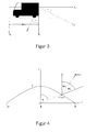
- Fig. 3 In Fig. 3 is shown that the camera viewing direction is inclined by an angle ⁇ against the (reverse) direction of travel.
- this transformation contains not only the tilt angle ⁇ , but the three Euler angles.
- the arctan ( y , x ) function with two arguments determines the phase of the complex number x + iy in the value range] - ⁇ , ⁇ ].
- the order of the arguments was chosen on the model of the ANSI-C function atan2 .
- the illustration by the Omnicam modeled here takes place in two steps: a reflection on a parabolic mirror followed by an orthographic image.
- s ( x , y ) or m ( x , y ) are unit vectors.
- r is the distance from the center of the image, measured in pixels.
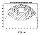
- ⁇ is the inclination of the viewing direction to the optical axis. This relationship can be helped by Fig. 4 and Eq. (25) derive.
- the azimuth ⁇ is the same in camera and image coordinates.
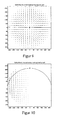
- a graph of this compression function shows Fig. 5 ,
- Fig. 3 shows how a tilted camera is moved by the vehicle, which moves in a horizontal plane.
- the horizon is the image of a parallel plane passing through the projection center, as in Fig. 7 shown.
- the main point of the camera is marked with x, the FOE with a +, the horizon as a yellow line.
- the grid elements now consist of vertical and horizontal sections of straight lines p i , l i , according to the explanation of equations (29) to (34), where the p i each have reference points on the straight line sections and l i represents one of two unit vectors in the direction of the respective grid elements, respectively. As indicated, these straight line sections are transformed into circular sections on the image sensor surface and these are displayed as a grid pattern.
- the fixed representation of the symbolic grid elements is now accomplished by the fact that in a - measured by a rotary encoder on the wheel - driving the distance s in the longitudinal direction of the vehicle all Auflie l i are shifted by the distance s against the direction of travel.
- p i New p i - s * e where e represents the unit vector in the vehicle longitudinal direction in the camera coordinate system.
- the driver does not necessarily have to constantly move his vehicle in order to determine the endangerment of objects in the manner described on the basis of the movement pattern in the image. It should therefore be made possible for him, e.g. by pressing a button to generate a repeat of the last motion sequence on the display system. This may e.g. the picture material of the last 5m driving distance with inserted driving tube, shown in an endless loop.
- Possible design elements of the symbolic driving tube which fulfill the conditions of clear geometric structure and transparency described in the last section, are e.g. the representation of the edge boundary by means of a grid pattern, a string of bars or a checkerboard pattern.
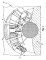
- FIG. 1 shows an image scene 10, in which the edge boundary of the free space is visualized by superposition of symbolically represented walls 16.
- the image data to be assigned to the real scene is distorted by the profitable use of a catadioptric camera.
- a catadioptric camera For a driver, however, are very easy to perceive the main objects in the environment, such as the vehicles 11 and 12, and the garage 13 with the roller shutter 14 very easy to recognize.
- the use of the catadioptric camera, the part 15 in the direction of travel of the own vehicle forms at the lower edge of the illustrated image data.
- Such a representation has the advantage that the driver is allowed to observe the potentially most collision-prone areas of the vehicle.
- FIG. 2 shows one too FIG. 1 identical image scene (20), here the edge boundary of the free space is visualized by superposition with a symbolically represented virtual Fahrschlauches (26) with chess bed pattern.
- a checkerboard pattern to highlight the edge boundaries in the viewing of the image scene on the display in a particularly catchy manner, the proper motion of the vehicle clearly. This is particularly advantageous when can be driven due to great narrowness with only very low speeds.
- the reference structure of the symbolic driving tube recorded in the same way makes it much easier for the driver to correct the distortions of the lens unconsciously assess and take into account.
- FIGS. 1 and 2 shown examples on the right side of the picture and left, where you can see the view of a crossing road.
- FIG. 2 Cornered corrugated boundaries of the rectangular tube shown the interpretation, which are the real down and up elements of the scene.
- the road is the lower element on the inside and the sky on the outer edge of the circular representation.
- the invention is suitable for monitoring the rear space when maneuvering a motor vehicle.
- the rear space for the driver is often not directly visible, so he is dependent on a particularly catchy presentation of the environment and the interaction of his vehicle therein.
- R ( x, y ) modulates the horizontal and vertical flux with the same prefactor. Therefore, R ( x , y ) only affects the length of the flow vectors, but not their direction. As shown, the direction of flow is determined only by the camera movement, ie by the location of the expansion point. For this translational movement, the direction of the flow vectors is thus independent of the depth structure of the environment.
- Fig. 12 shows the depth map of a corridor.
- the sidebar shows the colors used to encode the depth.
- the depth was calculated according to Eq. (39) for the vertical walls and Eq. (42) calculated for the horizontal floor and the ceiling.
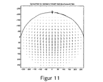
- Fig. 13 shows the theoretically expected flow for this corridor. He can according to Eq. (70f) for the vertical walls and Eq. (75f) for floor and ceiling. Horizon and FOE are marked as above by the yellow arc or a plus sign.
- the Fig. 14 and 15 show the same flow field as color-coded images respectively for the horizontal and vertical flow.
Landscapes
- Engineering & Computer Science (AREA)
- Multimedia (AREA)
- Mechanical Engineering (AREA)
- Transportation (AREA)
- Radar, Positioning & Navigation (AREA)
- Remote Sensing (AREA)
- Human Computer Interaction (AREA)
- Chemical & Material Sciences (AREA)
- Combustion & Propulsion (AREA)
- Traffic Control Systems (AREA)
- Closed-Circuit Television Systems (AREA)
- Image Processing (AREA)
Claims (17)
- Procédé de surveillance d'un espace libre dans le sens de la marche d'un véhicule automobile, selon lequel des données d'image de l'environnement du véhicule qui se trouve dans la zone du sens de la marche sont enregistrées au moyen d'un système de caméra, en outre sur la base de paramètres de fonctionnement et de la taille du véhicule automobile l'espace libre tridimensionnel nécessaire à une marche sans entrave étant calculé à l'avance dans une unité de traitement de signal, et au moins la partie des données d'image enregistrées représentant l'espace libre nécessaire étant indiquée au conducteur du véhicule automobile, l'affichage des données d'image s'effectuant ici essentiellement à partir d'une perspective montrant comment l'environnement du véhicule se trouvant dans le sens de la marche serait présenter au conducteur du véhicule à vue directe, et au moins les données d'image associées à l'espace libre tridimensionnel étant soumises à un traitement ultérieur, un résultat dudit traitement ultérieur étant que le conducteur du véhicule est informé si un espace libre suffisant pour une marche sans entrave est disponible ou non, caractérisé en ce qu'au moins des parties des données d'image de l'espace libre nécessaire enregistrées par le système de caméra sont indiquées au conducteur de véhicule sur un écran, les données d'image affichées étant superposées par une représentation symbolique des délimitation de bord (16, 26) de l'espace libre nécessaire déterminé par le calcul préalable dans l'unité de traitement de signal et la représentation de la délimitation de bord (16, 26) étant représentée au moyen d'un quadrillage, d'une juxtaposition de barres ou d'un échiquier.
- Procédé selon la revendication 1, caractérisé en ce que le traitement ultérieur prend en compte des modifications dynamiques et temporelles dans les données d'image.
- Procédé selon l'une quelconque des revendications précédentes, caractérisé en ce que l'information que l'espace libre n'est pas suffisant pour une marche sans entrave, est transmise au conducteur de véhicule par un moyen d'avertissement, en particulier par un émetteur de signal optique, acoustique ou perceptible de manière tactile.
- Procédé selon l'une quelconque des revendications précédentes, caractérisé en ce que l'information que pour une marche sans entrave il n'existe pas d'espace libre suffisant à disposition, est transmise au conducteur par la représentation en image d'au moins une partie des données d'image traitées ultérieurement, dans ces données d'images chaque objet (11, 12), faisant obstacle dans l'espace libre nécessaire, étant mis en valeur par rapport aux autres objets d'image.
- Procédé selon la revendication 4, caractérisé en ce que la mise en valeur s'effectue de telle sorte que les objets (11, 12) faisant obstacle sont superposés par des symboles lesquels représentent leur sens de mouvement et / ou leur vitesse de mouvement.
- Procédé selon l'une quelconque des revendications précédentes, caractérisé en ce que la représentation par symboles des délimitations de bord s'effectue par des parois représentées par des symboles.
- Procédé selon l'une quelconque des revendications précédentes, caractérisé en ce que la représentation par symboles des délimitations de bord s'effectue par des parois représentées par des symboles et par une zone de plafond et / ou par une zone de plancher en forme de tunnel.
- Procédé selon l'une quelconque des revendications précédentes, caractérisé en ce que les zones de paroi et / ou la zone de plafond et / ou la zone de plancher sont conçues de telle sorte qu'elles- possèdent une structure géométrique pouvant être identifiées de manière claire et sans ambiguïté,- permettent une « vue » sur la scène vidéo enregistrée et- sont calculées de telle sorte qu'elles semblent également figées dans la direction longitudinale pendant le mouvement du véhicule.
- Procédé selon l'une quelconque des revendications précédentes, caractérisé en ce que la scène indiquée au conducteur du véhicule est mémorisée de manière temporaire au moins pour une certaine durée de temps précédente ou un certain trajet parcouru et peut être appelée par le conducteur du véhicule pour être revue.
- Procédé selon l'une quelconque des revendications précédentes 6 à 9, caractérisé en ce que les données d'image de caméra superposées avec les délimitations de bord de l'espace libre nécessaire sont fournies à un procédé de traitement d'image se basant sur le flux optique, lequel compare le mouvement des délimitations de bord fixes dans les données d'image au mouvement réel des objets sur l'image, chaque endroit sur l'image dans lequel le modèle de flux est plus petit que le flux réel mesuré étant évalué comme un objet de collision potentiel.
- Procédé selon la revendication 10, caractérisé en ce qu'en présence d'un objet de collision potentiel, celui-ci est mis en valeur optiquement, par exemple grâce à des couleurs, et / ou est indiqué au conducteur du véhicule par un signal d'avertissement.
- Dispositif de surveillance de l'espace libre dans le sens de la marche d'un véhicule, doté d'un système de caméra pour enregistrer des données d'image à partir de l'environnement du véhicule se trouvant dans le sens de la marche du véhicule, d'une unité de traitement de signal, laquelle est reliée à des capteurs pour enregistrer les paramètres de fonctionnement du véhicule, et d'une mémoire dans laquelle les données relatives à la taille du véhicule sont enregistrées, ainsi que d'une unité d'affichage reliée à l'unité de traitement de signal destinée à afficher au moins la partie des données d'image représentant l'espace libre tridimensionnel nécessaire, la mémoire associée à l'unité de traitement de signal étant conçue et organisée de telle sorte qu'une pluralité de jeux de données relatives aux différentes dimensions du véhicule soient mémorisés, lesquelles sont sélectionnées de manière ciblée et peuvent être mises à disposition de l'unité de traitement de signal, que le dispositif comprenne une unité de traitement d'image qui se base sur le flux optique, au moyen de laquelle les données d'image superposées avec les délimitations de bord de l'espace libre nécessaire peuvent être traitées, que le mouvement des délimitations de bord fixes dans les données d'image puisse être comparé au mouvement réel des objets dans l'image, de sorte que chaque endroit dans l'image dans lequel le modèle de flux est plus petit que le flux réel mesuré puisse être évalué comme un objet de collision potentiel, et que le dispositif, une unité pour le traitement d'image, soit relié à l'écran du conducteur du véhicule et /ou les émetteurs de signal d'avertissement, de sorte que les objets de collision potentielle puissent être mis en valeur dans les données d'image représentées ou que le conducteur du véhicule puisse être averti d'une collision potentielle avec ces objets (11, 12), et que la représentation de la délimitation de bord (16, 25) soit représentée au moyen d'un quadrillage, d'une juxtaposition de barres ou d'un échiquier.
- Dispositif selon la revendication 12, caractérisé en ce que le moyen de sélection ciblée d'un jeu de données mémorisé dans la mémoire est un clavier pouvant être utilisé par le conducteur du véhicule.
- Dispositif selon l'une quelconque des revendications précédentes, caractérisé en ce que le moyen d'échange d'au moins un jeu de données mémorisé dans la mémoire comprend un dispositif de communication pour le transfert à distance de données.
- Dispositif selon l'une quelconque des revendications précédentes, caractérisé en ce que le système de caméra comprend au moins une caméra catadioptrique.
- Dispositif selon l'une quelconque des revendications précédentes, caractérisé en ce que le dispositif comprend une mémoire pour la mémorisation provisoire d'au moins des parties des données d'image indiquées au conducteur du véhicule, et en ce qu'il est prévu un moyen avec lequel le conducteur du véhicule peut appeler ces données d'image temporairement mémorisées afin qu'il puisse les revoir.
- Utilisation du procédé et du dispositif selon l'une quelconque des revendications précédentes, pour la surveillance de l'espace arrière lors de la manoeuvre de véhicules.
Applications Claiming Priority (2)
| Application Number | Priority Date | Filing Date | Title |
|---|---|---|---|
| DE10317044A DE10317044A1 (de) | 2003-04-11 | 2003-04-11 | Freiraumüberwachung bei Kraftfahrzeugen |
| DE10317044 | 2003-04-11 |
Publications (3)
| Publication Number | Publication Date |
|---|---|
| EP1470958A2 EP1470958A2 (fr) | 2004-10-27 |
| EP1470958A3 EP1470958A3 (fr) | 2005-09-14 |
| EP1470958B1 true EP1470958B1 (fr) | 2012-06-13 |
Family
ID=32946377
Family Applications (1)
| Application Number | Title | Priority Date | Filing Date |
|---|---|---|---|
| EP04007890A Expired - Lifetime EP1470958B1 (fr) | 2003-04-11 | 2004-04-01 | Surveillance d'un espace libre pour véhicules à moteur |
Country Status (3)
| Country | Link |
|---|---|
| US (1) | US7136754B2 (fr) |
| EP (1) | EP1470958B1 (fr) |
| DE (1) | DE10317044A1 (fr) |
Cited By (1)
| Publication number | Priority date | Publication date | Assignee | Title |
|---|---|---|---|---|
| DE102013222846A1 (de) | 2013-11-11 | 2015-05-13 | Robert Bosch Gmbh | Verfahren und Vorrichtung zur Erkennung der Durchfahrtsmöglichkeit eines Fahrzeugs |
Families Citing this family (102)
| Publication number | Priority date | Publication date | Assignee | Title |
|---|---|---|---|---|
| US20050206225A1 (en) * | 2004-03-18 | 2005-09-22 | Ford Global Technologies, Llc | Method and apparatus for predicting the position of a trailer relative to a vehicle |
| DE102005004394B4 (de) * | 2005-01-31 | 2012-09-06 | Continental Automotive Gmbh | Rückfahrtassistent |
| DE102005018408A1 (de) * | 2005-04-20 | 2006-10-26 | Valeo Schalter Und Sensoren Gmbh | Verfahren und Vorrichtung zur Auswertung von Abstandsmessdaten eines Abstandsmesssystems eines Kraftfahrzeugs |
| EP1717757A1 (fr) * | 2005-04-28 | 2006-11-02 | Bayerische Motoren Werke Aktiengesellschaft | Procédé pour la représentation graphique de l'environnement d'un véhicule automobile |
| DE102005063445B4 (de) * | 2005-10-27 | 2010-05-20 | Daimler Ag | Rangierhilfe für Fahrer von Fahrzeugen bzw. Fahrzeuggespannen, welche aus gegeneinander knickbare Fahrzeugelemente bestehen |
| DE102005062151B4 (de) * | 2005-12-22 | 2007-09-13 | Daimlerchrysler Ag | Verfahren und Vorrichtung zur Unterstützung eines Fahrzeugführers bei der Passage von Fahrwegverengungen |
| DE102006008981A1 (de) * | 2006-02-23 | 2007-08-30 | Siemens Ag | Assistenzsystem zur Unterstützung eines Fahrers |
| FR2913798B1 (fr) * | 2007-03-16 | 2011-09-02 | Valeo Vision | Procede de determination de passage d'un vehicule dans un goulet |
| DE102006041651A1 (de) * | 2006-08-24 | 2008-03-13 | Valeo Schalter Und Sensoren Gmbh | Verfahren zur Ermittlung der Passierfähigkeit eines Fahrzeugs durch einen Fahrbahnengpass und Fahrerassistenzsystem hierfür |
| EP1892688B1 (fr) | 2006-08-24 | 2010-09-01 | Valeo Vision | Procédé de détermination de passage d'un véhicule dans un goulet |
| DE102006047131A1 (de) | 2006-10-05 | 2008-04-10 | Robert Bosch Gmbh | Verfahren zum automatischen Steuern eines Fahrzeugs |
| GB2447672B (en) | 2007-03-21 | 2011-12-14 | Ford Global Tech Llc | Vehicle manoeuvring aids |
| US8233045B2 (en) * | 2007-07-16 | 2012-07-31 | Trw Automotive U.S. Llc | Method and apparatus for distortion correction and image enhancing of a vehicle rear viewing system |
| DE102008044073A1 (de) | 2008-11-26 | 2010-05-27 | Robert Bosch Gmbh | Steuereinrichtung zur Einparkunterstützung |
| FR2942064A1 (fr) * | 2009-02-10 | 2010-08-13 | Peugeot Citroen Automobiles Sa | Procede et systeme pour alerter un conducteur de vehicule |
| US8493409B2 (en) * | 2009-08-18 | 2013-07-23 | Behavioral Recognition Systems, Inc. | Visualizing and updating sequences and segments in a video surveillance system |
| DE102009053807A1 (de) * | 2009-11-18 | 2011-05-19 | Conti Temic Microelectronic Gmbh | Verfahren zum Unterstützen eines Fahrers beim Einparken eines Fahrzeugs |
| JP5035643B2 (ja) | 2010-03-18 | 2012-09-26 | アイシン精機株式会社 | 画像表示装置 |
| US9230419B2 (en) | 2010-07-27 | 2016-01-05 | Rite-Hite Holding Corporation | Methods and apparatus to detect and warn proximate entities of interest |
| DE102010064277B4 (de) | 2010-12-28 | 2024-03-14 | Robert Bosch Gmbh | Sicherheitsmerkmal in einem Fahrerassistenzsystem mit Rückfahrkamera |
| DE102011013774A1 (de) | 2011-03-12 | 2012-09-13 | Daimler Ag | Verfahren zum Erfassen und Darstellen einer Fahrzeugumgebung eines Fahrzeugs |
| US9937953B2 (en) | 2011-04-19 | 2018-04-10 | Ford Global Technologies, Llc | Trailer backup offset determination |
| US9493187B2 (en) | 2011-04-19 | 2016-11-15 | Ford Global Technologies, Llc | Control for trailer backup assist system |
| US9683848B2 (en) | 2011-04-19 | 2017-06-20 | Ford Global Technologies, Llc | System for determining hitch angle |
| US9926008B2 (en) | 2011-04-19 | 2018-03-27 | Ford Global Technologies, Llc | Trailer backup assist system with waypoint selection |
| US9708000B2 (en) | 2011-04-19 | 2017-07-18 | Ford Global Technologies, Llc | Trajectory planner for a trailer backup assist system |
| US9499200B2 (en) | 2011-04-19 | 2016-11-22 | Ford Global Technologies, Llc | Trailer backup assist system with object detection |
| US9346396B2 (en) | 2011-04-19 | 2016-05-24 | Ford Global Technologies, Llc | Supplemental vehicle lighting system for vision based target detection |
| US9555832B2 (en) | 2011-04-19 | 2017-01-31 | Ford Global Technologies, Llc | Display system utilizing vehicle and trailer dynamics |
| US9290204B2 (en) | 2011-04-19 | 2016-03-22 | Ford Global Technologies, Llc | Hitch angle monitoring system and method |
| US9854209B2 (en) | 2011-04-19 | 2017-12-26 | Ford Global Technologies, Llc | Display system utilizing vehicle and trailer dynamics |
| US9723274B2 (en) | 2011-04-19 | 2017-08-01 | Ford Global Technologies, Llc | System and method for adjusting an image capture setting |
| US9500497B2 (en) | 2011-04-19 | 2016-11-22 | Ford Global Technologies, Llc | System and method of inputting an intended backing path |
| US9238483B2 (en) | 2011-04-19 | 2016-01-19 | Ford Global Technologies, Llc | Trailer backup assist system with trajectory planner for multiple waypoints |
| US9783230B2 (en) | 2011-04-19 | 2017-10-10 | Ford Global Technologies, Llc | Trailer backup assist system with off-shoot correction |
| US9506774B2 (en) | 2011-04-19 | 2016-11-29 | Ford Global Technologies, Llc | Method of inputting a path for a vehicle and trailer |
| US9374562B2 (en) | 2011-04-19 | 2016-06-21 | Ford Global Technologies, Llc | System and method for calculating a horizontal camera to target distance |
| US9248858B2 (en) | 2011-04-19 | 2016-02-02 | Ford Global Technologies | Trailer backup assist system |
| US9969428B2 (en) | 2011-04-19 | 2018-05-15 | Ford Global Technologies, Llc | Trailer backup assist system with waypoint selection |
| US9434414B2 (en) | 2011-04-19 | 2016-09-06 | Ford Global Technologies, Llc | System and method for determining a hitch angle offset |
| US8909426B2 (en) | 2011-04-19 | 2014-12-09 | Ford Global Technologies | Trailer path curvature control for trailer backup assist |
| US9290202B2 (en) | 2011-04-19 | 2016-03-22 | Ford Global Technologies, Llc | System and method of calibrating a trailer backup assist system |
| DE102011082483A1 (de) | 2011-09-12 | 2013-03-14 | Robert Bosch Gmbh | Verfahren zur Unterstützung eines Fahrers eines Kraftfahrzeugs |
| US9606542B2 (en) | 2012-01-12 | 2017-03-28 | International Business Machines Corporation | Discovery and monitoring of an environment using a plurality of robots |
| DE102012006679A1 (de) | 2012-03-31 | 2012-09-20 | Daimler Ag | Verfahren zum Erfassen und Darstellen einer Fahrzeugumgebung eines Fahrzeugs |
| DE102012211034A1 (de) * | 2012-06-27 | 2014-01-02 | Robert Bosch Gmbh | Höhendetektion |
| US9227563B2 (en) * | 2012-09-14 | 2016-01-05 | Bendix Commercial Vehicle Systems Llc | Backward movement indicator apparatus for a vehicle |
| DE102012025322B4 (de) | 2012-12-22 | 2014-08-21 | Audi Ag | Kraftfahrzeug mit Kamera-Monitor-System |
| US9511799B2 (en) | 2013-02-04 | 2016-12-06 | Ford Global Technologies, Llc | Object avoidance for a trailer backup assist system |
| US9592851B2 (en) | 2013-02-04 | 2017-03-14 | Ford Global Technologies, Llc | Control modes for a trailer backup assist system |
| JP6149676B2 (ja) * | 2013-10-09 | 2017-06-21 | 富士通株式会社 | 画像処理装置、画像処理方法、及び、プログラム |
| US9352777B2 (en) | 2013-10-31 | 2016-05-31 | Ford Global Technologies, Llc | Methods and systems for configuring of a trailer maneuvering system |
| WO2015116022A1 (fr) * | 2014-01-28 | 2015-08-06 | GM Global Technology Operations LLC | Conscience de la situation pour un véhicule |
| DE102014203353A1 (de) * | 2014-02-25 | 2015-08-27 | Volkswagen Aktiengesellschaft | Verfahren zum Unterstützen eines Fahrers bei der Passage einer Fahrwegverengung und Fahrerassistenzsystem dafür |
| US9233710B2 (en) | 2014-03-06 | 2016-01-12 | Ford Global Technologies, Llc | Trailer backup assist system using gesture commands and method |
| US9623904B2 (en) | 2014-06-03 | 2017-04-18 | Ford Global Technologies, Llc | Trailer curvature control with adaptive trailer length estimation |
| DE102014008578B4 (de) | 2014-06-12 | 2016-02-18 | Audi Ag | Verfahren zur Ermittlung von Positionsdaten zur Nutzung beim Betrieb eines Fahrzeugsystems eines Kraftfahrzeugs und Positionsdatenermittlungs- und-verteilssystem |
| US9540043B2 (en) | 2014-07-30 | 2017-01-10 | Ford Global Technologies, Llc | Trailer backup assist system with active trailer braking for curvature control |
| US9315212B1 (en) | 2014-10-13 | 2016-04-19 | Ford Global Technologies, Llc | Trailer sensor module and associated method of wireless trailer identification and motion estimation |
| JP6541334B2 (ja) * | 2014-11-05 | 2019-07-10 | キヤノン株式会社 | 画像処理装置、画像処理方法、およびプログラム |
| US9522677B2 (en) | 2014-12-05 | 2016-12-20 | Ford Global Technologies, Llc | Mitigation of input device failure and mode management |
| US9533683B2 (en) | 2014-12-05 | 2017-01-03 | Ford Global Technologies, Llc | Sensor failure mitigation system and mode management |
| US9607242B2 (en) | 2015-01-16 | 2017-03-28 | Ford Global Technologies, Llc | Target monitoring system with lens cleaning device |
| US9522699B2 (en) | 2015-02-05 | 2016-12-20 | Ford Global Technologies, Llc | Trailer backup assist system with adaptive steering angle limits |
| US10286950B2 (en) | 2015-02-10 | 2019-05-14 | Ford Global Technologies, Llc | Speed optimized trajectory control for motor vehicles |
| US9616923B2 (en) | 2015-03-03 | 2017-04-11 | Ford Global Technologies, Llc | Topographical integration for trailer backup assist system |
| US9623859B2 (en) | 2015-04-03 | 2017-04-18 | Ford Global Technologies, Llc | Trailer curvature control and mode management with powertrain and brake support |
| US9840240B2 (en) | 2015-04-09 | 2017-12-12 | Ford Global Technologies, Llc | Trailer backup aid speed limiting via braking |
| US9744972B2 (en) | 2015-04-09 | 2017-08-29 | Ford Global Technologies, Llc | Trailer backup aid speed limiting via braking |
| GB2533983A (en) * | 2015-06-04 | 2016-07-13 | Ford Global Tech Llc | Parking assist method and system |
| US9676377B2 (en) | 2015-06-17 | 2017-06-13 | Ford Global Technologies, Llc | Speed limiting comfort enhancement |
| US9896126B2 (en) | 2015-07-08 | 2018-02-20 | Ford Global Technologies, Llc | Jackknife detection for vehicle reversing a trailer |
| US9896130B2 (en) | 2015-09-11 | 2018-02-20 | Ford Global Technologies, Llc | Guidance system for a vehicle reversing a trailer along an intended backing path |
| US9981662B2 (en) | 2015-10-15 | 2018-05-29 | Ford Global Technologies, Llc | Speed limiting comfort enhancement |
| US9836060B2 (en) | 2015-10-28 | 2017-12-05 | Ford Global Technologies, Llc | Trailer backup assist system with target management |
| US9895945B2 (en) | 2015-12-08 | 2018-02-20 | Ford Global Technologies, Llc | Trailer backup assist system with hitch assist |
| US10011228B2 (en) | 2015-12-17 | 2018-07-03 | Ford Global Technologies, Llc | Hitch angle detection for trailer backup assist system using multiple imaging devices |
| US10127459B2 (en) | 2015-12-17 | 2018-11-13 | Ford Global Technologies, Llc | Trailer type identification system |
| US9610975B1 (en) | 2015-12-17 | 2017-04-04 | Ford Global Technologies, Llc | Hitch angle detection for trailer backup assist system |
| US10112646B2 (en) | 2016-05-05 | 2018-10-30 | Ford Global Technologies, Llc | Turn recovery human machine interface for trailer backup assist |
| US10106193B2 (en) | 2016-07-01 | 2018-10-23 | Ford Global Technologies, Llc | Enhanced yaw rate trailer angle detection initialization |
| DE102016216567A1 (de) | 2016-09-01 | 2018-03-01 | Bayerische Motoren Werke Aktiengesellschaft | Verfahren, Vorrichtung, Computerprogramm und Computerprogrammprodukt zur Detektion einer Verengung eines Fahrwegs eines Fahrzeugs |
| DE102016218853A1 (de) | 2016-09-29 | 2018-03-29 | Conti Temic Microelectronic Gmbh | Detektion und Validierung von Objekten aus Bildern einer Kamera |
| DE102016218849A1 (de) | 2016-09-29 | 2018-03-29 | Conti Temic Microelectronic Gmbh | Detektion und Tracking von Objekten aus Bildern einer Kamera |
| DE102016218852A1 (de) | 2016-09-29 | 2018-03-29 | Conti Temic Microelectronic Gmbh | Detektion von Objekten aus Bildern einer Kamera |
| US10773721B2 (en) | 2016-10-21 | 2020-09-15 | Ford Global Technologies, Llc | Control method using trailer yaw rate measurements for trailer backup assist |
| JP6730177B2 (ja) * | 2016-12-28 | 2020-07-29 | 株式会社デンソーテン | 画像生成装置および画像生成方法 |
| US10604184B2 (en) | 2017-08-31 | 2020-03-31 | Ford Global Technologies, Llc | Adaptive steering control for robustness to errors in estimated or user-supplied trailer parameters |
| US10710585B2 (en) | 2017-09-01 | 2020-07-14 | Ford Global Technologies, Llc | Trailer backup assist system with predictive hitch angle functionality |
| US10730553B2 (en) | 2017-09-27 | 2020-08-04 | Ford Global Technologies, Llc | Adaptive steering control for robustness to errors in estimated or user-supplied trailer parameters |
| DE102017126600A1 (de) | 2017-11-13 | 2019-05-16 | Valeo Schalter Und Sensoren Gmbh | Freiraumüberwachung |
| DE102017221191B4 (de) * | 2017-11-27 | 2019-06-13 | Volkswagen Aktiengesellschaft | Verfahren zur Anzeige des Verlaufs einer Sicherheitszone vor einem Fahrzeug oder einem Objekt mit einer Anzeigeeinheit, Vorrichtung zur Durchführung des Verfahrens sowie Kraftfahrzeug und Computerprogramm |
| US10445598B1 (en) | 2018-04-03 | 2019-10-15 | Ford Global Technologies, Llc | Garage door detection for a vehicle |
| DE102018209334A1 (de) * | 2018-06-12 | 2019-12-12 | Robert Bosch Gmbh | Verfahren zur Visualisierung |
| DE102018127061B3 (de) | 2018-10-30 | 2019-11-14 | Daimler Ag | Verfahren zum Betrieb eines Assistenzsystems eines Fahrzeuges, Vorrichtung zur Durchführung des Verfahrens und Fahrzeug |
| US10814912B2 (en) | 2018-11-28 | 2020-10-27 | Ford Global Technologies, Llc | Trailer backup assist system having advanced user mode with selectable hitch angle limits |
| DE102019123778A1 (de) | 2019-09-05 | 2021-03-11 | Valeo Schalter Und Sensoren Gmbh | Darstellen einer Fahrzeugumgebung zum Bewegen des Fahrzeugs zu einer Zielposition |
| FR3104524B1 (fr) * | 2019-12-13 | 2021-12-31 | Renault Sas | Procédé et dispositif d’assistance au stationnement d’un véhicule et véhicule comportant un tel dispositif. |
| CN111601279A (zh) * | 2020-05-14 | 2020-08-28 | 大陆投资(中国)有限公司 | 在车载显示器中显示动态交通态势的方法和车载系统 |
| US11661722B2 (en) | 2020-11-19 | 2023-05-30 | Deere & Company | System and method for customized visualization of the surroundings of self-propelled work vehicles |
| EP4068153A1 (fr) * | 2021-03-31 | 2022-10-05 | Honda Research Institute Europe GmbH | Système d'aide à la conduite avancé pour aider un conducteur d'un véhicule |
| US20240116437A1 (en) * | 2022-10-05 | 2024-04-11 | Ford Global Technologies, Llc | Trailer sideswipe avoidance system |
Family Cites Families (13)
| Publication number | Priority date | Publication date | Assignee | Title |
|---|---|---|---|---|
| JP2769052B2 (ja) * | 1991-04-09 | 1998-06-25 | インターナショナル・ビジネス・マシーンズ・コーポレイション | 自律移動機械、移動機械の制御装置及び方法 |
| JP2952816B2 (ja) * | 1996-12-17 | 1999-09-27 | 本田技研工業株式会社 | 車両の自動操舵装置 |
| US7366595B1 (en) * | 1999-06-25 | 2008-04-29 | Seiko Epson Corporation | Vehicle drive assist system |
| DE19947766A1 (de) * | 1999-10-02 | 2001-05-10 | Bosch Gmbh Robert | Einrichtung zur Überwachung der Umgebung eines einparkenden Fahrzeugs |
| JP2001216520A (ja) * | 2000-01-31 | 2001-08-10 | Yazaki Corp | 車両用周辺監視装置 |
| DE10031590B4 (de) * | 2000-06-29 | 2007-10-04 | Volkswagen Aktiengesellschaft | Adaptive Rückfahrkamera |
| EP1167120B1 (fr) * | 2000-06-30 | 2014-08-27 | Panasonic Corporation | Dispositif de rendu pour faciliter le stationnement d'un véhicule |
| JP3619753B2 (ja) * | 2000-07-03 | 2005-02-16 | トヨタ自動車株式会社 | 移動体の後方視界表示装置 |
| DE10059900A1 (de) * | 2000-12-01 | 2002-06-13 | Daimler Chrysler Ag | Darstellung von bildhafter Umgebungsinformation |
| DE10128792B4 (de) * | 2001-05-08 | 2005-06-09 | Daimlerchrysler Ag | Kollisionsschutz für Fahrzeuge |
| DE10131720B4 (de) * | 2001-06-30 | 2017-02-23 | Robert Bosch Gmbh | Head-Up Display System und Verfahren |
| DE10138719A1 (de) * | 2001-08-07 | 2003-03-06 | Siemens Ag | Verfahren und Vorrichtung zur Darstellung von Fahrhinweisen, insbesondere in Auto-Navigationssystemen |
| DE10139735B4 (de) * | 2001-08-13 | 2004-12-16 | Scharfenberger, Kurt | Lastkraftwagen |
-
2003
- 2003-04-11 DE DE10317044A patent/DE10317044A1/de not_active Withdrawn
-
2004
- 2004-04-01 EP EP04007890A patent/EP1470958B1/fr not_active Expired - Lifetime
- 2004-04-12 US US10/822,513 patent/US7136754B2/en not_active Expired - Fee Related
Cited By (2)
| Publication number | Priority date | Publication date | Assignee | Title |
|---|---|---|---|---|
| DE102013222846A1 (de) | 2013-11-11 | 2015-05-13 | Robert Bosch Gmbh | Verfahren und Vorrichtung zur Erkennung der Durchfahrtsmöglichkeit eines Fahrzeugs |
| EP2879116A1 (fr) | 2013-11-11 | 2015-06-03 | Robert Bosch Gmbh | Procédé et dispositif de reconnaissance de la possibilité de passage d'un véhicule |
Also Published As
| Publication number | Publication date |
|---|---|
| US20040220724A1 (en) | 2004-11-04 |
| EP1470958A3 (fr) | 2005-09-14 |
| DE10317044A1 (de) | 2004-10-21 |
| US7136754B2 (en) | 2006-11-14 |
| EP1470958A2 (fr) | 2004-10-27 |
Similar Documents
| Publication | Publication Date | Title |
|---|---|---|
| EP1470958B1 (fr) | Surveillance d'un espace libre pour véhicules à moteur | |
| EP3501897B1 (fr) | Système de visualisation permettant d'apprehender l'environnement d'un véhicule | |
| DE102008034594B4 (de) | Verfahren sowie Informationssystem zur Information eines Insassen eines Fahrzeuges | |
| EP2805183B1 (fr) | Procédé et dispositif de visualisation de l'environnement d'un véhicule | |
| EP2603413B1 (fr) | Procédé d'assistance à une manoeuvre de stationnement d'un véhicule à moteur, système d'aide à la conduite, et véhicule à moteur | |
| EP1147032B1 (fr) | Dispositif pour surveiller les abords d'un vehicule en cours de stationnement | |
| DE102006003538B3 (de) | Verfahren zum Zusammenfügen mehrerer Bildaufnahmen zu einem Gesamtbild in der Vogelperspektive | |
| DE102012025322B4 (de) | Kraftfahrzeug mit Kamera-Monitor-System | |
| EP2559236B1 (fr) | Procédé d'affichage d'une image sur un équipement d'affichage dans un véhicule, système d'assistance au conducteur et véhicule | |
| DE102007059735A1 (de) | Stereo-Sichtsystem für Fahrzeuge zur Erkennung seitlich liegender Hindernisse | |
| DE102008034606A1 (de) | Verfahren zur Darstellung der Umgebung eines Fahrzeugs auf einer mobilen Einheit | |
| DE10035223A1 (de) | Vorrichtung und Verfahren zur Überwachung der Umgebung eines Objekts | |
| WO2016005232A1 (fr) | Assemblage de sous-images pour former une image d'un environnement d'un moyen de transport | |
| DE102012018326A1 (de) | Verfahren und Vorrichtung für ein bildgebendes Fahrerassistenzsystem mit verdeckungsfreier Umsichtfunktion | |
| DE102012018325A1 (de) | Verfahren und Vorrichtung für ein bildgebendes Fahrerassistenzsystem mit adaptiver Umsichtdarstellung | |
| WO2010025792A1 (fr) | Procédé et dispositif permettant de surveiller les alentours d'un véhicule | |
| DE102009035422B4 (de) | Verfahren zur geometrischen Bildtransformation | |
| DE102010051204A1 (de) | Verfahren zum Darstellen eines Hindernisses und Abbildungsvorrichtung | |
| DE102016115313A1 (de) | Verfahren zum Unterstützen eines Fahrers eines Gespanns, Fahrerassistenzsystem sowie Gespann | |
| EP2500216A1 (fr) | Procédé et dispositif pour un système d'assistance au conducteur produisant des images | |
| DE10297590B4 (de) | Fahrunterstützungssystem, Bildausgabevorrichtung und mit Kamera ausgestatteter Stab | |
| DE102012005277B3 (de) | Heckbereichssichtsystem | |
| EP2804785B1 (fr) | Système d'affichage destiné à un véhicule | |
| DE102013010233A1 (de) | Verfahren zum Anzeigen von Umgebungsinformationen in einem Fahrzeug | |
| DE102014111186B4 (de) | Verfahren zum anzeigen eines erfassten bilds an einer anzeigeeinrichtung eines gefahrenen fahrzeugs |
Legal Events
| Date | Code | Title | Description |
|---|---|---|---|
| PUAI | Public reference made under article 153(3) epc to a published international application that has entered the european phase |
Free format text: ORIGINAL CODE: 0009012 |
|
| AK | Designated contracting states |
Kind code of ref document: A2 Designated state(s): AT BE BG CH CY CZ DE DK EE ES FI FR GB GR HU IE IT LI LU MC NL PL PT RO SE SI SK TR |
|
| AX | Request for extension of the european patent |
Extension state: AL HR LT LV MK |
|
| PUAL | Search report despatched |
Free format text: ORIGINAL CODE: 0009013 |
|
| AK | Designated contracting states |
Kind code of ref document: A3 Designated state(s): AT BE BG CH CY CZ DE DK EE ES FI FR GB GR HU IE IT LI LU MC NL PL PT RO SE SI SK TR |
|
| AX | Request for extension of the european patent |
Extension state: AL HR LT LV MK |
|
| 17P | Request for examination filed |
Effective date: 20051110 |
|
| AKX | Designation fees paid |
Designated state(s): DE FR GB |
|
| RAP1 | Party data changed (applicant data changed or rights of an application transferred) |
Owner name: DAIMLERCHRYSLER AG |
|
| RAP1 | Party data changed (applicant data changed or rights of an application transferred) |
Owner name: DAIMLER AG |
|
| 17Q | First examination report despatched |
Effective date: 20100311 |
|
| GRAP | Despatch of communication of intention to grant a patent |
Free format text: ORIGINAL CODE: EPIDOSNIGR1 |
|
| GRAC | Information related to communication of intention to grant a patent modified |
Free format text: ORIGINAL CODE: EPIDOSCIGR1 |
|
| GRAS | Grant fee paid |
Free format text: ORIGINAL CODE: EPIDOSNIGR3 |
|
| GRAA | (expected) grant |
Free format text: ORIGINAL CODE: 0009210 |
|
| AK | Designated contracting states |
Kind code of ref document: B1 Designated state(s): DE FR GB |
|
| REG | Reference to a national code |
Ref country code: GB Ref legal event code: FG4D Free format text: NOT ENGLISH |
|
| REG | Reference to a national code |
Ref country code: DE Ref legal event code: R096 Ref document number: 502004013571 Country of ref document: DE Effective date: 20120809 |
|
| PLBE | No opposition filed within time limit |
Free format text: ORIGINAL CODE: 0009261 |
|
| STAA | Information on the status of an ep patent application or granted ep patent |
Free format text: STATUS: NO OPPOSITION FILED WITHIN TIME LIMIT |
|
| 26N | No opposition filed |
Effective date: 20130314 |
|
| REG | Reference to a national code |
Ref country code: DE Ref legal event code: R097 Ref document number: 502004013571 Country of ref document: DE Effective date: 20130314 |
|
| GBPC | Gb: european patent ceased through non-payment of renewal fee |
Effective date: 20130401 |
|
| PG25 | Lapsed in a contracting state [announced via postgrant information from national office to epo] |
Ref country code: DE Free format text: LAPSE BECAUSE OF NON-PAYMENT OF DUE FEES Effective date: 20131101 Ref country code: GB Free format text: LAPSE BECAUSE OF NON-PAYMENT OF DUE FEES Effective date: 20130401 |
|
| REG | Reference to a national code |
Ref country code: FR Ref legal event code: ST Effective date: 20131231 |
|
| REG | Reference to a national code |
Ref country code: DE Ref legal event code: R119 Ref document number: 502004013571 Country of ref document: DE Effective date: 20131101 |
|
| PG25 | Lapsed in a contracting state [announced via postgrant information from national office to epo] |
Ref country code: FR Free format text: LAPSE BECAUSE OF NON-PAYMENT OF DUE FEES Effective date: 20130430 |