EP1470951A2 - Dispositif de réglage à cliquets - Google Patents
Dispositif de réglage à cliquets Download PDFInfo
- Publication number
- EP1470951A2 EP1470951A2 EP04008811A EP04008811A EP1470951A2 EP 1470951 A2 EP1470951 A2 EP 1470951A2 EP 04008811 A EP04008811 A EP 04008811A EP 04008811 A EP04008811 A EP 04008811A EP 1470951 A2 EP1470951 A2 EP 1470951A2
- Authority
- EP
- European Patent Office
- Prior art keywords
- ratchet
- adjusting device
- actuating element
- displacement
- elements
- Prior art date
- Legal status (The legal status is an assumption and is not a legal conclusion. Google has not performed a legal analysis and makes no representation as to the accuracy of the status listed.)
- Granted
Links
- 238000006073 displacement reaction Methods 0.000 claims description 50
- 230000001154 acute effect Effects 0.000 claims description 5
- 230000009471 action Effects 0.000 abstract description 3
- 238000000034 method Methods 0.000 description 6
- 230000008569 process Effects 0.000 description 6
- 229910000639 Spring steel Inorganic materials 0.000 description 2
- 230000000903 blocking effect Effects 0.000 description 2
- 230000000694 effects Effects 0.000 description 2
- 230000002028 premature Effects 0.000 description 2
- 238000004873 anchoring Methods 0.000 description 1
- 238000010276 construction Methods 0.000 description 1
- 238000011109 contamination Methods 0.000 description 1
- 230000000977 initiatory effect Effects 0.000 description 1
- 230000003993 interaction Effects 0.000 description 1
- 239000002184 metal Substances 0.000 description 1
- 230000004048 modification Effects 0.000 description 1
- 238000012986 modification Methods 0.000 description 1
Images


Classifications
-
- B—PERFORMING OPERATIONS; TRANSPORTING
- B60—VEHICLES IN GENERAL
- B60N—SEATS SPECIALLY ADAPTED FOR VEHICLES; VEHICLE PASSENGER ACCOMMODATION NOT OTHERWISE PROVIDED FOR
- B60N2/00—Seats specially adapted for vehicles; Arrangement or mounting of seats in vehicles
- B60N2/02—Seats specially adapted for vehicles; Arrangement or mounting of seats in vehicles the seat or part thereof being movable, e.g. adjustable
- B60N2/04—Seats specially adapted for vehicles; Arrangement or mounting of seats in vehicles the seat or part thereof being movable, e.g. adjustable the whole seat being movable
- B60N2/06—Seats specially adapted for vehicles; Arrangement or mounting of seats in vehicles the seat or part thereof being movable, e.g. adjustable the whole seat being movable slidable
- B60N2/08—Seats specially adapted for vehicles; Arrangement or mounting of seats in vehicles the seat or part thereof being movable, e.g. adjustable the whole seat being movable slidable characterised by the locking device
- B60N2/0831—Movement of the latch
- B60N2/0837—Movement of the latch pivoting
- B60N2/0856—Movement of the latch pivoting about a vertical axis
-
- B—PERFORMING OPERATIONS; TRANSPORTING
- B60—VEHICLES IN GENERAL
- B60N—SEATS SPECIALLY ADAPTED FOR VEHICLES; VEHICLE PASSENGER ACCOMMODATION NOT OTHERWISE PROVIDED FOR
- B60N2/00—Seats specially adapted for vehicles; Arrangement or mounting of seats in vehicles
- B60N2/02—Seats specially adapted for vehicles; Arrangement or mounting of seats in vehicles the seat or part thereof being movable, e.g. adjustable
- B60N2/04—Seats specially adapted for vehicles; Arrangement or mounting of seats in vehicles the seat or part thereof being movable, e.g. adjustable the whole seat being movable
- B60N2/06—Seats specially adapted for vehicles; Arrangement or mounting of seats in vehicles the seat or part thereof being movable, e.g. adjustable the whole seat being movable slidable
- B60N2/08—Seats specially adapted for vehicles; Arrangement or mounting of seats in vehicles the seat or part thereof being movable, e.g. adjustable the whole seat being movable slidable characterised by the locking device
- B60N2/0806—Seats specially adapted for vehicles; Arrangement or mounting of seats in vehicles the seat or part thereof being movable, e.g. adjustable the whole seat being movable slidable characterised by the locking device with pin alignment systems, e.g. with at least one of a plurality of locking pins always aligned w.r.t. at least one of a plurality of pin-receiving elements
-
- B—PERFORMING OPERATIONS; TRANSPORTING
- B60—VEHICLES IN GENERAL
- B60N—SEATS SPECIALLY ADAPTED FOR VEHICLES; VEHICLE PASSENGER ACCOMMODATION NOT OTHERWISE PROVIDED FOR
- B60N2/00—Seats specially adapted for vehicles; Arrangement or mounting of seats in vehicles
- B60N2/02—Seats specially adapted for vehicles; Arrangement or mounting of seats in vehicles the seat or part thereof being movable, e.g. adjustable
- B60N2/04—Seats specially adapted for vehicles; Arrangement or mounting of seats in vehicles the seat or part thereof being movable, e.g. adjustable the whole seat being movable
- B60N2/06—Seats specially adapted for vehicles; Arrangement or mounting of seats in vehicles the seat or part thereof being movable, e.g. adjustable the whole seat being movable slidable
- B60N2/08—Seats specially adapted for vehicles; Arrangement or mounting of seats in vehicles the seat or part thereof being movable, e.g. adjustable the whole seat being movable slidable characterised by the locking device
- B60N2/0812—Location of the latch
- B60N2/0818—Location of the latch inside the rail
-
- B—PERFORMING OPERATIONS; TRANSPORTING
- B60—VEHICLES IN GENERAL
- B60N—SEATS SPECIALLY ADAPTED FOR VEHICLES; VEHICLE PASSENGER ACCOMMODATION NOT OTHERWISE PROVIDED FOR
- B60N2/00—Seats specially adapted for vehicles; Arrangement or mounting of seats in vehicles
- B60N2/02—Seats specially adapted for vehicles; Arrangement or mounting of seats in vehicles the seat or part thereof being movable, e.g. adjustable
- B60N2/04—Seats specially adapted for vehicles; Arrangement or mounting of seats in vehicles the seat or part thereof being movable, e.g. adjustable the whole seat being movable
- B60N2/06—Seats specially adapted for vehicles; Arrangement or mounting of seats in vehicles the seat or part thereof being movable, e.g. adjustable the whole seat being movable slidable
- B60N2/08—Seats specially adapted for vehicles; Arrangement or mounting of seats in vehicles the seat or part thereof being movable, e.g. adjustable the whole seat being movable slidable characterised by the locking device
- B60N2/0831—Movement of the latch
- B60N2/0837—Movement of the latch pivoting
- B60N2/085—Movement of the latch pivoting about a transversal axis
-
- G—PHYSICS
- G05—CONTROLLING; REGULATING
- G05G—CONTROL DEVICES OR SYSTEMS INSOFAR AS CHARACTERISED BY MECHANICAL FEATURES ONLY
- G05G5/00—Means for preventing, limiting or returning the movements of parts of a control mechanism, e.g. locking controlling member
- G05G5/06—Means for preventing, limiting or returning the movements of parts of a control mechanism, e.g. locking controlling member for holding members in one or a limited number of definite positions only
-
- G—PHYSICS
- G05—CONTROLLING; REGULATING
- G05G—CONTROL DEVICES OR SYSTEMS INSOFAR AS CHARACTERISED BY MECHANICAL FEATURES ONLY
- G05G5/00—Means for preventing, limiting or returning the movements of parts of a control mechanism, e.g. locking controlling member
- G05G5/12—Means for preventing, limiting or returning the movements of parts of a control mechanism, e.g. locking controlling member for holding members in an indefinite number of positions, e.g. by a toothed quadrant
- G05G5/14—Means for preventing, limiting or returning the movements of parts of a control mechanism, e.g. locking controlling member for holding members in an indefinite number of positions, e.g. by a toothed quadrant by locking a member with respect to a fixed quadrant, rod, or the like
- G05G5/18—Means for preventing, limiting or returning the movements of parts of a control mechanism, e.g. locking controlling member for holding members in an indefinite number of positions, e.g. by a toothed quadrant by locking a member with respect to a fixed quadrant, rod, or the like by positive interengagement, e.g. by a pawl
-
- Y—GENERAL TAGGING OF NEW TECHNOLOGICAL DEVELOPMENTS; GENERAL TAGGING OF CROSS-SECTIONAL TECHNOLOGIES SPANNING OVER SEVERAL SECTIONS OF THE IPC; TECHNICAL SUBJECTS COVERED BY FORMER USPC CROSS-REFERENCE ART COLLECTIONS [XRACs] AND DIGESTS
- Y10—TECHNICAL SUBJECTS COVERED BY FORMER USPC
- Y10T—TECHNICAL SUBJECTS COVERED BY FORMER US CLASSIFICATION
- Y10T74/00—Machine element or mechanism
- Y10T74/20—Control lever and linkage systems
- Y10T74/20576—Elements
- Y10T74/20636—Detents
- Y10T74/20672—Lever engaging rack
- Y10T74/20684—Lever carried pawl
-
- Y—GENERAL TAGGING OF NEW TECHNOLOGICAL DEVELOPMENTS; GENERAL TAGGING OF CROSS-SECTIONAL TECHNOLOGIES SPANNING OVER SEVERAL SECTIONS OF THE IPC; TECHNICAL SUBJECTS COVERED BY FORMER USPC CROSS-REFERENCE ART COLLECTIONS [XRACs] AND DIGESTS
- Y10—TECHNICAL SUBJECTS COVERED BY FORMER USPC
- Y10T—TECHNICAL SUBJECTS COVERED BY FORMER US CLASSIFICATION
- Y10T74/00—Machine element or mechanism
- Y10T74/21—Elements
- Y10T74/2133—Pawls and ratchets
- Y10T74/2136—Pivoted pawls
- Y10T74/214—Multiple tooth
-
- Y—GENERAL TAGGING OF NEW TECHNOLOGICAL DEVELOPMENTS; GENERAL TAGGING OF CROSS-SECTIONAL TECHNOLOGIES SPANNING OVER SEVERAL SECTIONS OF THE IPC; TECHNICAL SUBJECTS COVERED BY FORMER USPC CROSS-REFERENCE ART COLLECTIONS [XRACs] AND DIGESTS
- Y10—TECHNICAL SUBJECTS COVERED BY FORMER USPC
- Y10T—TECHNICAL SUBJECTS COVERED BY FORMER US CLASSIFICATION
- Y10T74/00—Machine element or mechanism
- Y10T74/21—Elements
- Y10T74/2133—Pawls and ratchets
- Y10T74/2141—Sliding pawls
Definitions
- the invention relates to a ratchet-like adjusting device for ratcheting displacement an adjusting body relative to a stationary base element by means of an elongated actuating element with attached to the adjustment body on both sides of the actuating element Linear gears according to the preamble of claim 1.
- Such linearly designed ratchet-like adjustment devices are, for example, in Vehicle seats used to form a seat plate of the vehicle seat with respect to a base frame slide forward or backward as desired.
- Such will also be Adjustment devices for gradually ratcheting adjustment of an adjustment body by means of an elongated actuator used for a height adjustment of the seat plate perform.
- a ratchet-like adjustment device one opposite a stationary base element, such as the base frame of a seat plate, has a displaceable adjusting body which is connected to the seat flap.
- the Adjustment body can by means of an elongated plate-shaped actuating element, at the end of which a handle is arranged, displaced relative to the base element are made by two axially pivotally mounted on the actuator spaced ratchet elements, which together form an opening angle, in engage a linear toothing of the adjustment body.
- the actuating element can be compared to the adjustment body can be moved back again by moving against this shifting movement Ratchet element from the linear toothing by means of a locking element fixed to the base element is barked out. This is against a forward shifting movement ratchet element acting on the actuating element due to the opening angle position arranged in such a way that it scrapes backwards over the teeth of the linear toothing.
- two ratchet elements are in the area of the first and second longitudinal sides of the actuating element pivotable in the actuating element stored.
- the two ratchet elements each assigned to a linear toothing point to their End faces as well as the teeth of the linear toothing are relatively small tooth sizes on, the teeth of the ratchet elements in the zigzag linear toothing after passing through the disengaging member at a relatively steep angle within a very short time Intervene time. This can lead to premature wear of both the teeth of the linear teeth as well as the ratchet elements, provided there are large adjustment forces for displacement of the adjustment body can be used.
- the object of the present invention is a ratchet-like adjustment device for ratcheting displacement of an adjustment body compared to a stationary one
- An essential point of the invention is that in a ratchet-like adjustment device, in which an elongated actuating element along on both sides of an adjusting body attached linear toothing is displaceable, the actuating element by means of the first Ratchet elements can be snapped into a first linear toothing and on a stationary one Base element two second ratchet elements are mounted, which block a sliding movement serve the adjusting body relative to the stationary base element and in the second linear toothing can be snapped into place.
- the first linear toothing acts as an on and off Output teeth for driving and driving the adjustment body by means of the actuating element and the second linear toothing as locking and braking toothing for Braking or blocking the sliding movement of the actuating element and the adjustment body relative to the stationary base element. Because of the connection the second ratchet elements with the base element by means of pivot bearings is a Ratchet connection between the base element and the adjustment body created that leads to an unwanted displacement of the adjustment body relative to the base element can be avoided.
- the linear gears also serve as guide limits for the slidable Actuating element, the adjusting body and the elongated actuating element being plate-shaped are trained. These can be stamped sheet metal parts.
- the one on the adjustment body attached linear gears point together with the elongated actuator and the ratchet elements with the exception of their swivel bearings same thickness. They are arranged side by side on the adjustment body, so that a small overall thickness of the adjusting device according to the invention is achieved.
- the adjusting device can advantageously be installed in a space-saving manner in a vehicle seat become.
- the adjustment device is a linear stepwise ratcheting adjustment of the adjustment body with respect to the stationary base element possible, whereby a quick and time-saving adjustment of the vehicle seat is possible.
- Every second ratchet element can be attached by means of at least one along a long side of the Actuator formed projection by moving the actuator can be swiveled out of the linear toothing, so that the sliding movement the actuating element a controlled engagement and disengagement of the second Ratchet elements is possible.
- the second linear toothing is arranged appropriately along the projections
- one of the ratchet elements is disengaged can be so as to enable the sliding movement in a predetermined direction.
- the ratchet elements are arranged at an angle opposite to one another, that the one ratchet element is a forward sliding movement and the second ratchet element a backward sliding movement of the adjustment body blocks or brakes. This is an automatic release the displacement movement of the adjustment body relative to the stationary base element achieved by moving the actuator.
- the teeth of the second linear toothing are designed such that their beveled Allow flanks to press obliquely against the end faces of the second ratchet elements. This enables the use of comparatively large teeth, which prevents premature wear of the teeth.
- the second ratchet elements are by means of at least one tension spring connecting the ratchet elements under the action of spring force pressed against the second linear toothing and are designed such that their end pieces by the projections against the spring force to move away the ratchet elements can be deflected by the linear toothing.
- the first ratchet elements are in the actuating element around a fictitious pivot axis aligned perpendicular to the displacement movement pivoted. For example, this can be done by arranging two of them spaced circular recesses along another long side of the Actuating element can be reached, one in each of the circular recesses Ratchet element with a circular bearing section pivotally mounted becomes.
- a space-saving storage of the first ratchet elements is easy achieved with respect to the total thickness of the adjusting device.
- the stationary base element has recesses which are associated with pins are in turn arranged on the first ratchet elements.
- the recesses serve to do this, the first ratchet elements are aligned orthogonally to the direction of displacement Pin in its pivoting movement depending on the displacement position of the Actuating element relative to the adjustment body and depending on the direction of displacement to control the actuator.
- the recesses each point such an edge course that by sliding along the pin on the Edges a disengaging pivoting movement during the displacement of the actuating element of a ratchet element and a latching pivoting movement of the further Ratchet element is reached. This has the consequence that only that ratchet element is arranged in the locked state, which is for taking the adjustment body is responsible by the actuating element in a predetermined direction.
- the first linear toothing is designed such that that it has end teeth at its ends, preferably one end tooth each, the Length dimensions in relation to the direction of displacement larger than length dimensions of the remaining teeth of the first linear toothing.
- These length dimensions of the End teeth can, for example, double the length of the remaining teeth be.
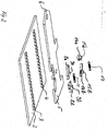
- FIG. 1 shows a top view of a first embodiment of the ratchet-like adjustment device for ratcheting displacement of an adjustment body compared to a stationary one Base element by means of an elongated actuating element with the adjusting body in the middle Position - that is, a zero position - in which the adjustment body is not displaced opposite the base element is present.
- the ratchet-like adjustment device according to the invention comprises the displaceably arranged in the fixed base element 1 adjustment body 2, the a first linear toothing 3 and a second linear toothing running parallel thereto 4 has on its surface.
- Both the base element 1 and the adjusting body 2 and an actuating element 5 are plate-shaped, that is, they have a small thickness.
- the actuating element 5 is displaceable between the first and second linear teeth 3, 4 arranged by lining up the individual teeth of the linear gears as guide limits for the first and second longitudinal sides 5a, 5b of the actuating element 5 serve.
- linear gears 3, 4 and the actuating element 5 have essentially the same thickness can have, the overall construction by means of a cover plate, not shown here easily covered on the top to prevent contamination and interference to avoid the functioning of the adjustment device by other objects.
- the actuating element 5 has at its one open end 6 one not shown here Handle on, which serves to actuate the actuating element 5 back and forth or forwards move backwards to make a linear, gradually ratcheting adjustment of the adjustment body 2 relative to the fixed base element 1.
- the actuating element 5 has circular cutouts on its first longitudinal side 5a 7a, 7b, which are spaced apart from one another and for supporting a circular-shaped mounting Bearing section of first ratchet elements 8a, 8b is used. In this way finds a pivotable mounting of the first ratchet elements 8a, 8b within the actuating element 5 instead.
- the ratchet elements 8a, 8b have pins 9a, 9b on the upper side, which are perpendicular to the displacement movement of the actuating element, which in relation to the image plane of FIG. 1 is aligned on the left and right side, extend.
- the pins 9a, 9b engage in recesses 10a, 10b, which are within the fixed base element, which is in this Area in a form not shown here extends over the first ratchet elements are.
- the recesses 10a, 10b serve to guide the pins 9a, 9b and cause them depending pivoting movements of the first predetermined by their specific edge profile Ratchet elements 8a, 8b by sliding the pins 9a, 9b along the edge of the recesses 10a, 10b.
- first ratchet elements 8a, 8b latch into the teeth of the first
- linear teeth 3 are the first ratchet elements by means of a tension spring 11 spring loaded.
- the spring force of the tension spring 11 causes the ratchet elements to be pressed 8a, 8b against the teeth of the first linear toothing 3 and counteracts a pivoting movement which can be carried out to disengage the ratchet elements 8a, 8b by the tension spring via a projection 12 which in the region of the first longitudinal side 5a of the Actuating element 5 is arranged, is deflected.
- two second ratchet elements 14a, 14b which act as braking and Locking toothing acting linear toothing 4 are pressed.
- the second ratchet elements 14a, 14b act as brakes and are protruding from the image plane Pin 15a, 15b pivotable on the fixed base element 1, which is in this area extends over the brakes 14a, 14b, as is not shown in this figure, pivoted.
- the brakes 14a, 14b are advantageously at an acute angle 16a, 16b the linear toothing that the one brake 14a against a forward Sliding movement and the further brake 14b against a rearward direction Sliding movement can act.
- the two brakes are spring-loaded by means of a tension spring 17.
- FIG. 2 is again to clarify the structure of the adjusting device according to the invention in a spatial exploded view without showing the fixed base element the adjustment device shown.
- the actuating element 5 and the first and second ratchet elements 8a, 8b, 14a, 14b have the same thickness.
- FIG. 2 clearly shows that the ratchet elements have pins 9a, 9b, 15a, 15b on the upper side, which guide the first ratchet elements 8a, 8b within the recesses 10a, 10b and for pivoting storage the brakes 14a, 14b serve within the fixed base element 1.
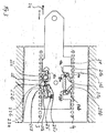
- Fig. 3 shows the adjustment device according to the invention at the beginning of a forward Adjustment process.
- the actuating element 5 is shifted to the left by 2 mm.
- the displacement of the actuating element with respect to the adjusting body 2 is determined by the arrow 24 indicated
- the disengaging pivoting movement of the brake 14a causes a displacement of the adjustment body 2 to the left in relation to the base plane 1 is only possible with respect to the image plane, since the brake 14a connected to the base element previously locked the adjusting body 2 compared to the base element 1.
- Fig. 4 is a plan view of the adjustment device according to the invention at the end of the forward directed adjustment or displacement process shown.
- the actuator 5 is now shifted to the left by a total of 10 mm, for example the slide-like adjustment body 2 is shifted to the left by, for example, 8 mm or has undergone a forward shift.
- the difference in the two displacement paths in the order of about 2 mm arises from the initial displacement of the actuating element 5 relative to the Adjustment body 2, as shown in Fig. 3.
- This initial displacement of the actuator 5 by, for example, 2 mm is used for the sliding engagement and disengagement of the first ratchet elements 8a, 8b and the disengagement of the brake 14a.
- Such a smooth one The engagement and disengagement process protects the individual teeth 22 of the ratchet elements and the individual input and output teeth of the first linear toothing 3 at one Interaction of those.
- a sliding engagement and disengagement by a tooth profile of the teeth 22 is the first Ratchet elements promoted, which is characterized in that the teeth on the on one side a beveled flank 22a and on the other side a perpendicular to the Have aligned flank 22b of the actuating element.
- Section 25c serves as a stop for the pin 9b and prevents a further forward displacement of the adjustment body 2 and the actuating element 5 with respect to the stationary base element 1, since the recess 10b is arranged within the fixed base element.
- the actuator 5 can a total of 10 mm to the right relative to the adjustment body 2.
- Fig. 5 the adjustment device according to the invention is moved back with a plan view Actuator 5 shown.
- the actuating element 5 takes again a zero position with respect to the stationary base element and caused by displacement of the projection 19a engages the brake 14a, which leads to a locked position of the Adjusting body 2 leads to the fixed base element 1.
- the seat plate with the adjustment body 2 is used, without an unwanted shift of the Seat plate can take place opposite the stationary base element.
- another adjustment cycle be initiated to move the seat plate with the adjustment body 2 even further.
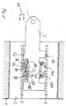
- FIG. 6 is a top view of the adjustment device according to the invention at the beginning of a backward adjustment process, that is, a displacement of the adjustment body 2 in shown the opposite direction.
- the actuating element 5, as indicated by the arrow 26 is indicated by 2 mm to the right with respect to the image plane, whereupon the brake 14b disengages due to the projection movement of the projection 19b.
- first ratchet element 8b snaps along due to the guidance of its pin 9b of the edge sections 25a and 25b from the linear toothing 3. At the same time it snaps first ratchet element 8a due to the guidance of its pin 9a along the edge section 25b into the linear toothing 3.
- Fig. 7 is a top view of the adjustment device after completing a reverse directed shifting process shown, in this case a total of three shift or Adjustment cycles with the intermediate shifting forward Actuator 5 were performed. This corresponds to a displacement of the adjustment body 2 by a total of 24 mm, as represented by reference numeral 27 becomes.
- FIGS. 8-10 show a second embodiment of the displacement device according to the invention shown.
- the second embodiment differs from the first embodiment in that end teeth 26a at ends of the first linear toothing 3 such are designed so that their length dimensions are double with respect to the direction of displacement as large as the length dimensions of the rest arranged between the end teeth 26a Teeth 26 are.
- the first ratchet element acting as a drive 8a, 8b brought completely out of engagement with the linear toothing 3.
- the sledge-like Adjustment body 2 can therefore no longer be moved.
- Such an automatic Blocking the entire adjustment device prevents unwanted in a simple manner move the adjustment body 2 too far with respect to the stationary base element 1.
- the elongate actuator be designed as a leaf spring steel sheet, the first ratchet elements and preferably also the second ratchet elements as resilient arms on both Longitudinal sides of the actuating element are arranged and also consist of leaf spring steel.
- the ratchet elements and the actuating element are formed in one piece.
- the ratchet elements designed like a spring leaf together with the actuating element via a projection connected to the stationary base element, the is arranged between the ratchet elements and the linear teeth, respectively the ratchet elements engaging in the linear toothing in their rest position the engaged position can be brought individually into a disengaged position.
- the linear toothing is again arranged on the adjustment body.
Landscapes
- Engineering & Computer Science (AREA)
- Aviation & Aerospace Engineering (AREA)
- Transportation (AREA)
- Mechanical Engineering (AREA)
- Physics & Mathematics (AREA)
- General Physics & Mathematics (AREA)
- Automation & Control Theory (AREA)
- Chairs For Special Purposes, Such As Reclining Chairs (AREA)
- Seats For Vehicles (AREA)
- Transmission Devices (AREA)
- Braking Arrangements (AREA)
Applications Claiming Priority (4)
| Application Number | Priority Date | Filing Date | Title |
|---|---|---|---|
| DE10318939 | 2003-04-26 | ||
| DE10318939 | 2003-04-26 | ||
| DE102004011054 | 2004-03-06 | ||
| DE102004011054A DE102004011054B4 (de) | 2003-04-26 | 2004-03-06 | Ratschenartige Verstellvorrichtung |
Publications (3)
| Publication Number | Publication Date |
|---|---|
| EP1470951A2 true EP1470951A2 (fr) | 2004-10-27 |
| EP1470951A3 EP1470951A3 (fr) | 2006-04-05 |
| EP1470951B1 EP1470951B1 (fr) | 2007-10-24 |
Family
ID=32963539
Family Applications (1)
| Application Number | Title | Priority Date | Filing Date |
|---|---|---|---|
| EP04008811A Expired - Lifetime EP1470951B1 (fr) | 2003-04-26 | 2004-04-14 | Dispositif de réglage à cliquets |
Country Status (4)
| Country | Link |
|---|---|
| US (1) | US7357051B2 (fr) |
| EP (1) | EP1470951B1 (fr) |
| CN (1) | CN100463815C (fr) |
| DE (1) | DE502004005308D1 (fr) |
Families Citing this family (6)
| Publication number | Priority date | Publication date | Assignee | Title |
|---|---|---|---|---|
| US8141951B2 (en) * | 2008-09-10 | 2012-03-27 | Excellerate Enterprise Co., Ltd. | Child safety seat |
| DE102010035430B4 (de) | 2010-08-26 | 2014-03-27 | Johnson Controls Gmbh | Verstellvorrichtung, insbesondere für einen Fahrzeugsitz |
| US9616785B2 (en) * | 2014-01-09 | 2017-04-11 | PAC Seating Systems, Inc. | Infinitely vertically adjustable drop down armrest mechanism |
| US10426269B1 (en) * | 2018-04-30 | 2019-10-01 | Buzz Seating, Inc. | Chair with appendage accommodations |
| KR102613446B1 (ko) * | 2018-12-20 | 2023-12-13 | 현대트랜시스 주식회사 | 차량용 시트 트랙 장치 |
| WO2022187615A2 (fr) | 2021-03-05 | 2022-09-09 | Camaco, LLC | Ensemble rail renforcé pour siège de véhicule |
Citations (1)
| Publication number | Priority date | Publication date | Assignee | Title |
|---|---|---|---|---|
| DE10039501A1 (de) | 2000-08-12 | 2002-02-28 | Grammer Ag | Verstell-Vorrichtung |
Family Cites Families (11)
| Publication number | Priority date | Publication date | Assignee | Title |
|---|---|---|---|---|
| US4012158A (en) * | 1975-09-15 | 1977-03-15 | Harper Henry J | Adjustable seat-back mechanism |
| US4451084A (en) * | 1981-12-14 | 1984-05-29 | Simmons Universal Corporation | Backrest height adjustment for office chair |
| US4639039A (en) * | 1985-09-10 | 1987-01-27 | Milsco Manufacturing Company | Height adjustment mechanism for chair backrest |
| US5324096A (en) * | 1992-03-02 | 1994-06-28 | Hon Industries Inc. | Adjustable height chair arm |
| DE4321720C2 (de) * | 1993-06-30 | 2001-08-16 | Keiper Gmbh & Co | Verriegelungssystem |
| IT239565Y1 (it) * | 1995-03-21 | 2001-03-05 | Miotto Internat Company | Dispositivo di regolazione dell'altezza di uno schienale di una sedia |
| US5586809A (en) * | 1995-08-04 | 1996-12-24 | Herman Miller, Inc. | Height adjustment mechanism for a chair backrest |
| US5664842A (en) * | 1996-05-24 | 1997-09-09 | Shin Yeh Enterprise Co., Ltd. | Height-adjustable armrest unit for a chair |
| US5695249A (en) * | 1996-06-24 | 1997-12-09 | Lotfi; Mehdian | Height adjustment mechanism for chair components |
| AUPP725498A0 (en) * | 1998-11-23 | 1998-12-17 | Klasse Pty Ltd | Back support improvement |
| US6533355B2 (en) * | 2001-03-28 | 2003-03-18 | Haworth, Inc. | Height-adjustment mechanism for a chair |
-
2004
- 2004-04-14 EP EP04008811A patent/EP1470951B1/fr not_active Expired - Lifetime
- 2004-04-14 DE DE502004005308T patent/DE502004005308D1/de not_active Expired - Lifetime
- 2004-04-19 CN CNB2004100367549A patent/CN100463815C/zh not_active Expired - Lifetime
- 2004-04-20 US US10/827,894 patent/US7357051B2/en active Active
Patent Citations (1)
| Publication number | Priority date | Publication date | Assignee | Title |
|---|---|---|---|---|
| DE10039501A1 (de) | 2000-08-12 | 2002-02-28 | Grammer Ag | Verstell-Vorrichtung |
Also Published As
| Publication number | Publication date |
|---|---|
| CN1550372A (zh) | 2004-12-01 |
| EP1470951B1 (fr) | 2007-10-24 |
| DE502004005308D1 (de) | 2007-12-06 |
| US7357051B2 (en) | 2008-04-15 |
| CN100463815C (zh) | 2009-02-25 |
| EP1470951A3 (fr) | 2006-04-05 |
| US20040221679A1 (en) | 2004-11-11 |
Similar Documents
| Publication | Publication Date | Title |
|---|---|---|
| DE102007049032B4 (de) | Zange | |
| DE102009059159B3 (de) | Lenksäule für ein Kraftfahrzeug | |
| EP1747117B1 (fr) | Systeme de store a element coulissant freine | |
| DE102015225488B3 (de) | Verstellbare Lenksäule für Kraftfahrzeuge mit Energieabsorptionsvorrichtung | |
| EP1989960B1 (fr) | Ferrure à cran d'arrêt | |
| DE102006009976A1 (de) | Radialverstellmechanismus zur Anwendung in einer Fahrzeugsitzbaugruppe | |
| EP2956274B1 (fr) | Dispositif de blocage desserrable, en particulier sur un outil de serrage | |
| DE10144063A1 (de) | Parksperre für ein Automatikgetriebe eines Kraftfahrzeuges | |
| DE29600996U1 (de) | Feststellbremse für Kraftfahrzeuge, Fahrzeuganhänger o.dgl. | |
| DE3038565C2 (de) | Heftapparat | |
| EP1180737A2 (fr) | Dispositif de réglage | |
| DE102010029051B4 (de) | Anschlaganordnung für schwenkbare Karosseriebauteile | |
| EP1470951B1 (fr) | Dispositif de réglage à cliquets | |
| EP1415833A2 (fr) | Rail de guidage, en particulier pour un store à enrouleur dans un véhicule | |
| DE19854943B4 (de) | Presswerkzeug zur Verbindung mit einem Antrieb | |
| DE102004013066A1 (de) | Spann- und Spreizvorrichtung | |
| CH688023A5 (de) | Bindungseinrichtung zwischen einem Schuh und einem Sportgeraet | |
| DE102006013108B4 (de) | Spannwerkzeug, insbesondere Spannzwinge, Spannstock oder Spreizzwinge | |
| DE2253732C3 (de) | Vorrichtung zum Verstellen des Ausgangsgliedes eines Bewegungsgetriebes | |
| DE102004011054B4 (de) | Ratschenartige Verstellvorrichtung | |
| DE102010045423B4 (de) | Feststellvorrichtung für verstellbare Kraftfahrzeuglenksäule | |
| EP0318720B1 (fr) | Dispositif automatique de réglage de la longueur d'un câble Bowden | |
| DE3304593A1 (de) | Nachstell- und zentriervorrichtung fuer servobremsen | |
| DE69605240T2 (de) | In zwei Richtungen wirkende Arretiervorrichtung in einer einstellbaren Steueranlage mit Bowdenzug oder Betätigungsstange | |
| DE3248053A1 (de) | Loesbare, auf unterschiedliche tuerdicken einstellbare dornbefestigung fuer tuerhandhaben |
Legal Events
| Date | Code | Title | Description |
|---|---|---|---|
| PUAI | Public reference made under article 153(3) epc to a published international application that has entered the european phase |
Free format text: ORIGINAL CODE: 0009012 |
|
| AK | Designated contracting states |
Kind code of ref document: A2 Designated state(s): AT BE BG CH CY CZ DE DK EE ES FI FR GB GR HU IE IT LI LU MC NL PL PT RO SE SI SK TR |
|
| AX | Request for extension of the european patent |
Extension state: AL HR LT LV MK |
|
| 17P | Request for examination filed |
Effective date: 20050311 |
|
| PUAL | Search report despatched |
Free format text: ORIGINAL CODE: 0009013 |
|
| AK | Designated contracting states |
Kind code of ref document: A3 Designated state(s): AT BE BG CH CY CZ DE DK EE ES FI FR GB GR HU IE IT LI LU MC NL PL PT RO SE SI SK TR |
|
| AX | Request for extension of the european patent |
Extension state: AL HR LT LV MK |
|
| GRAP | Despatch of communication of intention to grant a patent |
Free format text: ORIGINAL CODE: EPIDOSNIGR1 |
|
| AKX | Designation fees paid |
Designated state(s): DE FR GB IT TR |
|
| GRAS | Grant fee paid |
Free format text: ORIGINAL CODE: EPIDOSNIGR3 |
|
| GRAA | (expected) grant |
Free format text: ORIGINAL CODE: 0009210 |
|
| AK | Designated contracting states |
Kind code of ref document: B1 Designated state(s): DE FR GB IT TR |
|
| REG | Reference to a national code |
Ref country code: GB Ref legal event code: FG4D Free format text: NOT ENGLISH |
|
| REF | Corresponds to: |
Ref document number: 502004005308 Country of ref document: DE Date of ref document: 20071206 Kind code of ref document: P |
|
| GBT | Gb: translation of ep patent filed (gb section 77(6)(a)/1977) |
Effective date: 20080130 |
|
| ET | Fr: translation filed | ||
| PLBE | No opposition filed within time limit |
Free format text: ORIGINAL CODE: 0009261 |
|
| STAA | Information on the status of an ep patent application or granted ep patent |
Free format text: STATUS: NO OPPOSITION FILED WITHIN TIME LIMIT |
|
| 26N | No opposition filed |
Effective date: 20080725 |
|
| PGFP | Annual fee paid to national office [announced via postgrant information from national office to epo] |
Ref country code: GB Payment date: 20140423 Year of fee payment: 11 |
|
| PGFP | Annual fee paid to national office [announced via postgrant information from national office to epo] |
Ref country code: FR Payment date: 20140416 Year of fee payment: 11 |
|
| GBPC | Gb: european patent ceased through non-payment of renewal fee |
Effective date: 20150414 |
|
| PG25 | Lapsed in a contracting state [announced via postgrant information from national office to epo] |
Ref country code: GB Free format text: LAPSE BECAUSE OF NON-PAYMENT OF DUE FEES Effective date: 20150414 |
|
| REG | Reference to a national code |
Ref country code: FR Ref legal event code: ST Effective date: 20151231 |
|
| PG25 | Lapsed in a contracting state [announced via postgrant information from national office to epo] |
Ref country code: FR Free format text: LAPSE BECAUSE OF NON-PAYMENT OF DUE FEES Effective date: 20150430 |
|
| PGFP | Annual fee paid to national office [announced via postgrant information from national office to epo] |
Ref country code: IT Payment date: 20160422 Year of fee payment: 13 Ref country code: TR Payment date: 20160405 Year of fee payment: 13 |
|
| PG25 | Lapsed in a contracting state [announced via postgrant information from national office to epo] |
Ref country code: IT Free format text: LAPSE BECAUSE OF NON-PAYMENT OF DUE FEES Effective date: 20170414 |
|
| PG25 | Lapsed in a contracting state [announced via postgrant information from national office to epo] |
Ref country code: TR Free format text: LAPSE BECAUSE OF NON-PAYMENT OF DUE FEES Effective date: 20170414 |
|
| PGFP | Annual fee paid to national office [announced via postgrant information from national office to epo] |
Ref country code: DE Payment date: 20230418 Year of fee payment: 20 |
|
| REG | Reference to a national code |
Ref country code: DE Ref legal event code: R071 Ref document number: 502004005308 Country of ref document: DE |