EP1470951A2 - Ratchet adjusting device - Google Patents
Ratchet adjusting device Download PDFInfo
- Publication number
- EP1470951A2 EP1470951A2 EP04008811A EP04008811A EP1470951A2 EP 1470951 A2 EP1470951 A2 EP 1470951A2 EP 04008811 A EP04008811 A EP 04008811A EP 04008811 A EP04008811 A EP 04008811A EP 1470951 A2 EP1470951 A2 EP 1470951A2
- Authority
- EP
- European Patent Office
- Prior art keywords
- ratchet
- adjusting device
- actuating element
- displacement
- elements
- Prior art date
- Legal status (The legal status is an assumption and is not a legal conclusion. Google has not performed a legal analysis and makes no representation as to the accuracy of the status listed.)
- Granted
Links
- 238000006073 displacement reaction Methods 0.000 claims description 50
- 230000001154 acute effect Effects 0.000 claims description 5
- 230000009471 action Effects 0.000 abstract description 3
- 238000000034 method Methods 0.000 description 6
- 230000008569 process Effects 0.000 description 6
- 229910000639 Spring steel Inorganic materials 0.000 description 2
- 230000000903 blocking effect Effects 0.000 description 2
- 230000000694 effects Effects 0.000 description 2
- 230000002028 premature Effects 0.000 description 2
- 238000004873 anchoring Methods 0.000 description 1
- 238000010276 construction Methods 0.000 description 1
- 238000011109 contamination Methods 0.000 description 1
- 230000000977 initiatory effect Effects 0.000 description 1
- 230000003993 interaction Effects 0.000 description 1
- 239000002184 metal Substances 0.000 description 1
- 230000004048 modification Effects 0.000 description 1
- 238000012986 modification Methods 0.000 description 1
Images


Classifications
-
- B—PERFORMING OPERATIONS; TRANSPORTING
- B60—VEHICLES IN GENERAL
- B60N—SEATS SPECIALLY ADAPTED FOR VEHICLES; VEHICLE PASSENGER ACCOMMODATION NOT OTHERWISE PROVIDED FOR
- B60N2/00—Seats specially adapted for vehicles; Arrangement or mounting of seats in vehicles
- B60N2/02—Seats specially adapted for vehicles; Arrangement or mounting of seats in vehicles the seat or part thereof being movable, e.g. adjustable
- B60N2/04—Seats specially adapted for vehicles; Arrangement or mounting of seats in vehicles the seat or part thereof being movable, e.g. adjustable the whole seat being movable
- B60N2/06—Seats specially adapted for vehicles; Arrangement or mounting of seats in vehicles the seat or part thereof being movable, e.g. adjustable the whole seat being movable slidable
- B60N2/08—Seats specially adapted for vehicles; Arrangement or mounting of seats in vehicles the seat or part thereof being movable, e.g. adjustable the whole seat being movable slidable characterised by the locking device
- B60N2/0831—Movement of the latch
- B60N2/0837—Movement of the latch pivoting
- B60N2/0856—Movement of the latch pivoting about a vertical axis
-
- B—PERFORMING OPERATIONS; TRANSPORTING
- B60—VEHICLES IN GENERAL
- B60N—SEATS SPECIALLY ADAPTED FOR VEHICLES; VEHICLE PASSENGER ACCOMMODATION NOT OTHERWISE PROVIDED FOR
- B60N2/00—Seats specially adapted for vehicles; Arrangement or mounting of seats in vehicles
- B60N2/02—Seats specially adapted for vehicles; Arrangement or mounting of seats in vehicles the seat or part thereof being movable, e.g. adjustable
- B60N2/04—Seats specially adapted for vehicles; Arrangement or mounting of seats in vehicles the seat or part thereof being movable, e.g. adjustable the whole seat being movable
- B60N2/06—Seats specially adapted for vehicles; Arrangement or mounting of seats in vehicles the seat or part thereof being movable, e.g. adjustable the whole seat being movable slidable
- B60N2/08—Seats specially adapted for vehicles; Arrangement or mounting of seats in vehicles the seat or part thereof being movable, e.g. adjustable the whole seat being movable slidable characterised by the locking device
- B60N2/0806—Seats specially adapted for vehicles; Arrangement or mounting of seats in vehicles the seat or part thereof being movable, e.g. adjustable the whole seat being movable slidable characterised by the locking device with pin alignment systems, e.g. with at least one of a plurality of locking pins always aligned w.r.t. at least one of a plurality of pin-receiving elements
-
- B—PERFORMING OPERATIONS; TRANSPORTING
- B60—VEHICLES IN GENERAL
- B60N—SEATS SPECIALLY ADAPTED FOR VEHICLES; VEHICLE PASSENGER ACCOMMODATION NOT OTHERWISE PROVIDED FOR
- B60N2/00—Seats specially adapted for vehicles; Arrangement or mounting of seats in vehicles
- B60N2/02—Seats specially adapted for vehicles; Arrangement or mounting of seats in vehicles the seat or part thereof being movable, e.g. adjustable
- B60N2/04—Seats specially adapted for vehicles; Arrangement or mounting of seats in vehicles the seat or part thereof being movable, e.g. adjustable the whole seat being movable
- B60N2/06—Seats specially adapted for vehicles; Arrangement or mounting of seats in vehicles the seat or part thereof being movable, e.g. adjustable the whole seat being movable slidable
- B60N2/08—Seats specially adapted for vehicles; Arrangement or mounting of seats in vehicles the seat or part thereof being movable, e.g. adjustable the whole seat being movable slidable characterised by the locking device
- B60N2/0812—Location of the latch
- B60N2/0818—Location of the latch inside the rail
-
- B—PERFORMING OPERATIONS; TRANSPORTING
- B60—VEHICLES IN GENERAL
- B60N—SEATS SPECIALLY ADAPTED FOR VEHICLES; VEHICLE PASSENGER ACCOMMODATION NOT OTHERWISE PROVIDED FOR
- B60N2/00—Seats specially adapted for vehicles; Arrangement or mounting of seats in vehicles
- B60N2/02—Seats specially adapted for vehicles; Arrangement or mounting of seats in vehicles the seat or part thereof being movable, e.g. adjustable
- B60N2/04—Seats specially adapted for vehicles; Arrangement or mounting of seats in vehicles the seat or part thereof being movable, e.g. adjustable the whole seat being movable
- B60N2/06—Seats specially adapted for vehicles; Arrangement or mounting of seats in vehicles the seat or part thereof being movable, e.g. adjustable the whole seat being movable slidable
- B60N2/08—Seats specially adapted for vehicles; Arrangement or mounting of seats in vehicles the seat or part thereof being movable, e.g. adjustable the whole seat being movable slidable characterised by the locking device
- B60N2/0831—Movement of the latch
- B60N2/0837—Movement of the latch pivoting
- B60N2/085—Movement of the latch pivoting about a transversal axis
-
- G—PHYSICS
- G05—CONTROLLING; REGULATING
- G05G—CONTROL DEVICES OR SYSTEMS INSOFAR AS CHARACTERISED BY MECHANICAL FEATURES ONLY
- G05G5/00—Means for preventing, limiting or returning the movements of parts of a control mechanism, e.g. locking controlling member
- G05G5/06—Means for preventing, limiting or returning the movements of parts of a control mechanism, e.g. locking controlling member for holding members in one or a limited number of definite positions only
-
- G—PHYSICS
- G05—CONTROLLING; REGULATING
- G05G—CONTROL DEVICES OR SYSTEMS INSOFAR AS CHARACTERISED BY MECHANICAL FEATURES ONLY
- G05G5/00—Means for preventing, limiting or returning the movements of parts of a control mechanism, e.g. locking controlling member
- G05G5/12—Means for preventing, limiting or returning the movements of parts of a control mechanism, e.g. locking controlling member for holding members in an indefinite number of positions, e.g. by a toothed quadrant
- G05G5/14—Means for preventing, limiting or returning the movements of parts of a control mechanism, e.g. locking controlling member for holding members in an indefinite number of positions, e.g. by a toothed quadrant by locking a member with respect to a fixed quadrant, rod, or the like
- G05G5/18—Means for preventing, limiting or returning the movements of parts of a control mechanism, e.g. locking controlling member for holding members in an indefinite number of positions, e.g. by a toothed quadrant by locking a member with respect to a fixed quadrant, rod, or the like by positive interengagement, e.g. by a pawl
-
- Y—GENERAL TAGGING OF NEW TECHNOLOGICAL DEVELOPMENTS; GENERAL TAGGING OF CROSS-SECTIONAL TECHNOLOGIES SPANNING OVER SEVERAL SECTIONS OF THE IPC; TECHNICAL SUBJECTS COVERED BY FORMER USPC CROSS-REFERENCE ART COLLECTIONS [XRACs] AND DIGESTS
- Y10—TECHNICAL SUBJECTS COVERED BY FORMER USPC
- Y10T—TECHNICAL SUBJECTS COVERED BY FORMER US CLASSIFICATION
- Y10T74/00—Machine element or mechanism
- Y10T74/20—Control lever and linkage systems
- Y10T74/20576—Elements
- Y10T74/20636—Detents
- Y10T74/20672—Lever engaging rack
- Y10T74/20684—Lever carried pawl
-
- Y—GENERAL TAGGING OF NEW TECHNOLOGICAL DEVELOPMENTS; GENERAL TAGGING OF CROSS-SECTIONAL TECHNOLOGIES SPANNING OVER SEVERAL SECTIONS OF THE IPC; TECHNICAL SUBJECTS COVERED BY FORMER USPC CROSS-REFERENCE ART COLLECTIONS [XRACs] AND DIGESTS
- Y10—TECHNICAL SUBJECTS COVERED BY FORMER USPC
- Y10T—TECHNICAL SUBJECTS COVERED BY FORMER US CLASSIFICATION
- Y10T74/00—Machine element or mechanism
- Y10T74/21—Elements
- Y10T74/2133—Pawls and ratchets
- Y10T74/2136—Pivoted pawls
- Y10T74/214—Multiple tooth
-
- Y—GENERAL TAGGING OF NEW TECHNOLOGICAL DEVELOPMENTS; GENERAL TAGGING OF CROSS-SECTIONAL TECHNOLOGIES SPANNING OVER SEVERAL SECTIONS OF THE IPC; TECHNICAL SUBJECTS COVERED BY FORMER USPC CROSS-REFERENCE ART COLLECTIONS [XRACs] AND DIGESTS
- Y10—TECHNICAL SUBJECTS COVERED BY FORMER USPC
- Y10T—TECHNICAL SUBJECTS COVERED BY FORMER US CLASSIFICATION
- Y10T74/00—Machine element or mechanism
- Y10T74/21—Elements
- Y10T74/2133—Pawls and ratchets
- Y10T74/2141—Sliding pawls
Landscapes
- Engineering & Computer Science (AREA)
- Aviation & Aerospace Engineering (AREA)
- Transportation (AREA)
- Mechanical Engineering (AREA)
- Physics & Mathematics (AREA)
- General Physics & Mathematics (AREA)
- Automation & Control Theory (AREA)
- Chairs For Special Purposes, Such As Reclining Chairs (AREA)
- Transmission Devices (AREA)
- Seats For Vehicles (AREA)
- Braking Arrangements (AREA)
Abstract
Description
Die Erfindung betrifft eine ratschenartige Verstellvorrichtung zum ratschenden Verschieben
eines Verstellkörpers gegenüber einem ortsfesten Basiselement mittels eines länglichen Betätigungselements
mit beidseitig des Betätigungselements an dem Verstellkörper angebrachten
Linearverzahnungen gemäß dem Oberbegriff des Patentanspruches 1.The invention relates to a ratchet-like adjusting device for ratcheting displacement
an adjusting body relative to a stationary base element by means of an elongated actuating element
with attached to the adjustment body on both sides of the actuating element
Linear gears according to the preamble of
Derartige linear ausgebildete ratschenartige Verstellvorrichtungen werden beispielsweise in Fahrzeugsitzen verwendet, um eine Sitzplatte des Fahrzeugsitzes in Bezug auf ein Grundgestell wunschgemäß nach vorne oder nach hinten zu schieben. Ebenso werden derartige Verstellvorrichtungen zum schrittweise ratschenden Verstellen eines Verstellkörpers mittels eines länglichen Betätigungselementes dafür verwendet, eine Höheneinstellung der Sitzplatte durchzuführen.Such linearly designed ratchet-like adjustment devices are, for example, in Vehicle seats used to form a seat plate of the vehicle seat with respect to a base frame slide forward or backward as desired. Such will also be Adjustment devices for gradually ratcheting adjustment of an adjustment body by means of an elongated actuator used for a height adjustment of the seat plate perform.
Aus der DE 100 39 501 A1 ist eine ratschenartige Verstellvorrichtung bekannt, die einen gegenüber einem ortsfesten Basiselement, wie beispielsweise das Grundgestell einer Sitzplatte, einen verschiebbaren Verstellkörper, der mit der Sitzpatte verbunden ist, aufweist. Der Verstellkörper kann mittels eines länglich ausgebildeten plattenförmigen Betätigungselementes, an dessen Ende ein Handgriff angeordnet ist, gegenüber dem Basiselement verschoben werden, indem zwei an dem Betätigungselement schwenkbar gelagerte axial voneinander beabstandete Ratschenelemente, die miteinander einen Öffnungswinkel einschließen, in eine Linearverzahnung des Verstellkörpers eingreifen. From DE 100 39 501 A1 a ratchet-like adjustment device is known, one opposite a stationary base element, such as the base frame of a seat plate, has a displaceable adjusting body which is connected to the seat flap. The Adjustment body can by means of an elongated plate-shaped actuating element, at the end of which a handle is arranged, displaced relative to the base element are made by two axially pivotally mounted on the actuator spaced ratchet elements, which together form an opening angle, in engage a linear toothing of the adjustment body.
Durch das Eingreifen beziehungsweise Einrasten der Ratschenelemente in die Linearverzahnung findet eine Mitnahme des Verstellkörpers bei Verschieben des Betätigungselementes statt.By engaging or snapping the ratchet elements into the linear toothing takes the adjustment body when moving the actuating element instead of.
Für die Erzielung des Ratscheneffektes kann das Betätigungselement gegenüber dem Verstellkörper wieder zurückbewegt werden, indem das gegen diese Verschiebebewegung gerichtete Ratschenelement mittels eines basiselementfesten Ausrastorganes aus der Linearverzahnung ausgerastet wird. Hierbei ist das gegen eine vorwärts gerichtete Verschiebebewegung des Betätigungselements wirkende Ratschenelement aufgrund der Öffnungswinkelstellung derart angeordnet, dass es rückwärts über Zähne der Linearverzahnung schabt.To achieve the ratchet effect, the actuating element can be compared to the adjustment body can be moved back again by moving against this shifting movement Ratchet element from the linear toothing by means of a locking element fixed to the base element is freaked out. This is against a forward shifting movement ratchet element acting on the actuating element due to the opening angle position arranged in such a way that it scrapes backwards over the teeth of the linear toothing.
Bei einer derartigen Verstellvorrichtung sind jeweils zwei Ratschenelemente im Bereich erster und zweiter Längsseiten des Betätigungselementes schwenkbar in dem Betätigungselement gelagert. Hierdurch wird zwar je nach Verschiebestellung des Betätigungselementes und der damit verbundenen Ratschenelemente bezüglich der beidseitig zu dem Betätigungselement angeordneten Linearverzahnungen eine Arretierung des Betätigungselements bezüglich des Verstellkörpers erreicht, jedoch ist keine Arretierungsvorrichtung zum Arretieren des Verstellkörpers oder des Betätigungselementes gegenüber dem ortsfesten Basiselement vorgesehen. Demzufolge besteht die Gefahr des ungewollten Verschiebens des Verstellkörpers gegenüber dem ortsfesten Basiselement.With such an adjustment device, two ratchet elements are in the area of the first and second longitudinal sides of the actuating element pivotable in the actuating element stored. As a result, depending on the shift position of the actuating element and the associated ratchet elements with respect to the actuating element on both sides arranged linear gears a locking of the actuating element achieved with respect to the adjustment body, but there is no locking device for locking of the adjustment body or of the actuating element with respect to the stationary base element intended. As a result, there is a risk that the Adjustment body compared to the stationary base element.
Die jeweils einer Linearverzahnung zugeordneten zwei Ratschenelemente weisen an ihren Stirnseiten ebenso wie die Zähne der Linearverzahnung relativ klein ausgebildete Zahngrößen auf, wobei die Zähne der Ratschenelemente in die zickzackförmige Linearverzahnung nach Durchlaufen des Ausrastorgans in einem relativ steilen Winkel innerhalb kürzester Zeit eingreifen. Dies kann zu einer vorzeitigen Abnutzung der Zähne sowohl der Linearverzahnung als auch der Ratschenelemente führen, sofern große Verstellkräfte zur Verschiebung des Verstellkörpers eingesetzt werden.The two ratchet elements each assigned to a linear toothing point to their End faces as well as the teeth of the linear toothing are relatively small tooth sizes on, the teeth of the ratchet elements in the zigzag linear toothing after passing through the disengaging member at a relatively steep angle within a very short time Intervene time. This can lead to premature wear of both the teeth of the linear teeth as well as the ratchet elements, provided there are large adjustment forces for displacement of the adjustment body can be used.
Weiterhin ist bei einer derartigen Verstellvorrichtung kein Anschlag für das Beenden einer vorwärts gerichteten Verschiebebewegung des Betätigungselementes mit dem Verstellkörper vorgesehen. Dies ermöglicht eine unkontrollierte Verschiebebewegung des Verstellkörpers gegenüber dem ortsfesten Basiselement. Furthermore, in such an adjustment device there is no stop for terminating one forward displacement movement of the actuating element with the adjusting body intended. This enables an uncontrolled displacement movement of the adjustment body opposite the stationary base element.
Demzufolge liegt der vorliegenden Erfindung die Aufgabe zugrunde, eine ratschenartige Verstellvorrichtung zum ratschenden Verschieben eines Verstellkörpers gegenüber einem ortsfesten Basiselement mittels eines länglichen Betätigungselements zur Verfügung zu stellen, bei der die Verschiebebewegungen des Verstellkörpers gegenüber dem ortsfesten Basiselement und des Betätigungselementes gegenüber dem Verstellkörper besser kontrolliert werden können.Accordingly, the object of the present invention is a ratchet-like adjustment device for ratcheting displacement of an adjustment body compared to a stationary one To provide the base element by means of an elongated actuating element, in which the displacement movements of the adjustment body relative to the stationary base element and the actuating element better controlled compared to the adjustment body can be.
Diese Aufgabe wird gemäß den Merkmalen des Patentanspruches 1 gelöst.This object is achieved according to the features of
Ein wesentlicher Punkt der Erfindung liegt darin, dass bei einer ratschenartigen Verstellvorrichtung, bei der ein längliches Betätigungselement entlang beidseitig an einem Verstellkörper angebrachten Linearverzahnungen verschiebbar ist, das Betätigungselement mittels erster Ratschenelemente in eine erste Linearverzahnung einrastbar ist und an einem ortsfesten Basiselement zwei zweite Ratschenelemente gelagert sind, die zum Sperren einer Verschiebebewegung des Verstellkörpers gegenüber dem ortsfesten Basiselement dienen und in die zweite Linearverzahnung einrastbar sind. Hierbei wirkt die erste Linearverzahnung als Anund Abtriebsverzahnung zum An- und Abtreiben des Verstellkörpers mittels des Betätigungselementes und die zweite Linearverzahnung als Sperr- und Bremsverzahnung zum Abbremsen beziehungsweise Sperren der Verschiebebewegung des Betätigungselementes und des Verstellkörpers gegenüber dem ortsfesten Basiselement. Aufgrund der Verbindung der zweiten Ratschenelemente mit dem Basiselement mittels Schwenklagerungen wird eine Ratschverbindung zwischen dem Basiselement und dem Verstellkörper geschaffen, die dazu führt, dass ein ungewolltes Verschieben des Verstellkörpers gegenüber dem Basiselement vermieden werden kann.An essential point of the invention is that in a ratchet-like adjustment device, in which an elongated actuating element along on both sides of an adjusting body attached linear toothing is displaceable, the actuating element by means of the first Ratchet elements can be snapped into a first linear toothing and on a stationary one Base element two second ratchet elements are mounted, which block a sliding movement serve the adjusting body relative to the stationary base element and in the second linear toothing can be snapped into place. Here, the first linear toothing acts as an on and off Output teeth for driving and driving the adjustment body by means of the actuating element and the second linear toothing as locking and braking toothing for Braking or blocking the sliding movement of the actuating element and the adjustment body relative to the stationary base element. Because of the connection the second ratchet elements with the base element by means of pivot bearings is a Ratchet connection between the base element and the adjustment body created that leads to an unwanted displacement of the adjustment body relative to the base element can be avoided.
Die Linearverzahnungen dienen zugleich als Führungsbegrenzungen für das verschiebbare Betätigungselement, wobei der Verstellkörper und das längliche Betätigungselement plattenförmig ausgebildet sind. Es kann sich hierbei um Stanzblechteile handeln. Die auf dem Verstellkörper angebrachten Linearverzahnungen weisen zusammen mit dem länglichen Betätigungselement und den Ratschenelementen mit Ausnahme derer Schwenklagerungen die gleiche Dicke auf. Sie sind auf dem Verstellkörper nebeneinander angeordnet, so dass eine geringe Gesamtdicke der erfindungsgemäßen Verstellvorrichtung erreicht wird. Auf diese Weise kann die Verstellvorrichtung vorteilhaft platzsparend in einem Fahrzeugsitz eingebaut werden.The linear gears also serve as guide limits for the slidable Actuating element, the adjusting body and the elongated actuating element being plate-shaped are trained. These can be stamped sheet metal parts. The one on the adjustment body attached linear gears point together with the elongated actuator and the ratchet elements with the exception of their swivel bearings same thickness. They are arranged side by side on the adjustment body, so that a small overall thickness of the adjusting device according to the invention is achieved. To this The adjusting device can advantageously be installed in a space-saving manner in a vehicle seat become.
Mit der erfindungsgemäßen Verstellvorrichtung ist eine lineare schrittweise ratschende Verstellung des Verstellkörpers im Bezug auf das ortsfeste Basiselement möglich, wodurch eine schnelle und zeitsparende Verstellung des Fahrzeugsitzes möglich ist.With the adjustment device according to the invention is a linear stepwise ratcheting adjustment of the adjustment body with respect to the stationary base element possible, whereby a quick and time-saving adjustment of the vehicle seat is possible.
Jedes zweite Ratschenelement kann mittels mindestens eines entlang einer Längsseite des Betätigungselementes ausgebildeten Vorsprunges durch Verschieben des Betätigungselementes schwenkend aus der Linearverzahnung ausgerastet werden, so dass durch die Verschiebebewegung des Betätigungselementes ein gesteuertes Ein- und Ausrasten der zweiten Ratschenelemente möglich ist. Bei einer Stellung der mit einem Abstand zueinander angeordneten zweiten Ratschenelemente mit jeweils einem spitzen Winkel zur Verlaufsrichtung der zweiten Linearverzahnung wird durch geeignete Anordnung der Vorsprünge entlang der Längsseite des Betätigungselementes erreicht, dass eines der Ratschenelemente ausgerastet werden kann, um so die Verschiebebewegung in eine vorbestimmte Richtung zu ermöglichen.Every second ratchet element can be attached by means of at least one along a long side of the Actuator formed projection by moving the actuator can be swiveled out of the linear toothing, so that the sliding movement the actuating element a controlled engagement and disengagement of the second Ratchet elements is possible. In the case of a position at a distance from one another second ratchet elements, each with an acute angle to the direction the second linear toothing is arranged appropriately along the projections On the long side of the actuating element, one of the ratchet elements is disengaged can be so as to enable the sliding movement in a predetermined direction.
Hierfür sind die Ratschenelemente in einem Winkel derart entgegengesetzt zueinander angeordnet, dass das eine Ratschenelement eine vorwärts gerichtete Verschiebebewegung und das zweite Ratschenelement eine rückwärts gerichtete Verschiebebewegung des Verstellkörpers blockiert beziehungsweise bremst. Auf diese Weise wird ein automatisches Freigeben der Verschiebebewegung des Verstellkörpers gegenüber dem ortsfesten Basiselement durch Verschieben des Betätigungselementes erreicht.For this purpose, the ratchet elements are arranged at an angle opposite to one another, that the one ratchet element is a forward sliding movement and the second ratchet element a backward sliding movement of the adjustment body blocks or brakes. This is an automatic release the displacement movement of the adjustment body relative to the stationary base element achieved by moving the actuator.
Die Zähne der zweiten Linearverzahnung sind derart ausgebildet, dass ihre abgeschrägten Flanken ein schräges Dagegendrücken von Stirnseiten der zweiten Ratschenelemente zulassen. Dies ermöglicht eine Verwendung von vergleichsweise groß ausgebildeten Zähnen, wodurch eine vorzeitige Abnutzung der Zähne vermieden wird.The teeth of the second linear toothing are designed such that their beveled Allow flanks to press obliquely against the end faces of the second ratchet elements. This enables the use of comparatively large teeth, which prevents premature wear of the teeth.
Die zweiten Ratschenelemente werden gemäß einer bevorzugten Ausführungsform mittels mindestens einer die Ratschenelemente verbindenden Zugfeder unter Federkraftbeaufschlagung gegen die zweite Linearverzahnung gedrückt und sind derart ausgebildet, dass ihre Endstücke durch die Vorsprünge entgegen der Federkraftbeaufschlagung zum Wegbewegen der Ratschenelemente von der Linearverzahnung ausgelenkt werden können.According to a preferred embodiment, the second ratchet elements are by means of at least one tension spring connecting the ratchet elements under the action of spring force pressed against the second linear toothing and are designed such that their end pieces by the projections against the spring force to move away the ratchet elements can be deflected by the linear toothing.
Gemäß einer bevorzugten Ausführungsform sind die ersten Ratschenelemente in dem Betätigungselement um eine senkrecht zu Verschiebebewegung ausgerichtete fiktive Schwenkachse schwenkbar gelagert. Beispielsweise kann dies durch die Anordnung von zwei voneinander beabstandeter kreisrunder Aussparungen entlang einer weiteren Längsseite des Betätigungselementes erreicht werden, wobei in die kreisrunden Aussparrungen jeweils ein Ratschenelement mit einem kreisrundenartigen Lagerabschnitt schwenkbeweglich gelagert wird. Somit wird auf einfache Weise eine platzsparende Lagerung der ersten Ratschenelemente bezüglich der Gesamtdicke der Verstellvorrichtung erreicht.According to a preferred embodiment, the first ratchet elements are in the actuating element around a fictitious pivot axis aligned perpendicular to the displacement movement pivoted. For example, this can be done by arranging two of them spaced circular recesses along another long side of the Actuating element can be reached, one in each of the circular recesses Ratchet element with a circular bearing section pivotally mounted becomes. Thus, a space-saving storage of the first ratchet elements is easy achieved with respect to the total thickness of the adjusting device.
Das ortsfeste Basiselement weist Ausnehmungen auf, die Zapfen zugeordnet sind, welche wiederum auf den ersten Ratschenelementen angeordnet sind. Die Ausnehmungen dienen dazu, die ersten Ratschenelemente mittels der orthogonal zur Verschieberichtung ausgerichteten Zapfen in ihrer Schwenkbewegung in Abhängigkeit von der Verschiebeposition des Betätigungselementes gegenüber dem Verstellkörper und in Abhängigkeit von der Verschieberichtung des Betätigungselementes zu steuern. Hierfür weisen die Ausnehmungen jeweils einen derartigen Randverlauf auf, dass mittels eines Entlanggleitens des Zapfens an den Rändern während der Verschiebung des Betätigungselementes eine ausrastende Schwenkbewegung des einen Ratschenelementes und eine einrastende Schwenkbewegung des weiteren Ratschenelementes erreicht wird. Dies hat zur Folge, dass lediglich dasjenige Ratschenelement im eingerasteten Zustand angeordnet ist, welches für die Mitnahme des Verstellkörpers durch das Betätigungselement in eine vorbestimmte Richtung zuständig ist.The stationary base element has recesses which are associated with pins are in turn arranged on the first ratchet elements. The recesses serve to do this, the first ratchet elements are aligned orthogonally to the direction of displacement Pin in its pivoting movement depending on the displacement position of the Actuating element relative to the adjustment body and depending on the direction of displacement to control the actuator. For this, the recesses each point such an edge course that by sliding along the pin on the Edges a disengaging pivoting movement during the displacement of the actuating element of a ratchet element and a latching pivoting movement of the further Ratchet element is reached. This has the consequence that only that ratchet element is arranged in the locked state, which is for taking the adjustment body is responsible by the actuating element in a predetermined direction.
Sobald die Zapfen am Ende der Ausnehmungen während einer vorwärts gerichteten Verschiebebewegung des Betätigungselementes angekommen sind, dient das Ende der Ausnehmungen als Anschlag für die Beendigung der vorwärts gerichteten Verschiebebewegung des Betätigungselementes. Anschließend findet eine rückwärts gerichtete Verschiebebewegung des Betätigungselementes statt, die dazu führt, dass das andere erste Ratschenelement aufgrund des Randverlaufes der Ausnehmungen nach einer vorbestimmten zurückgelegten Strecke in die erste Linearverzahnung einrastet. Auf diese Weise kann mittels der ersten Ratschenelemente, die nun beide im eingerasteten Zustand vorliegen, eine zusätzliche Sperrwirkung bezüglich jeglicher Verschiebung des Betätigungselementes gegenüber dem Verstellkörper erreicht werden.As soon as the pins at the end of the recesses during a forward sliding movement the actuator has arrived, the end of the recesses as a stop for the termination of the forward shifting movement of the actuator. Then there is a backward shifting movement of the actuating element, which leads to the other first ratchet element based on the edge course of the recesses after a predetermined distance The distance snaps into the first linear toothing. In this way, by means of first ratchet elements, both of which are now in the locked state, an additional one Locking effect with respect to any displacement of the actuator the adjustment body can be reached.
Gemäß einer bevorzugten Ausführungsform ist die erste Linearverzahnung derart ausgebildet, dass sie an ihren Enden Endzähne, vorzugsweise jeweils einen Endzahn, aufweist, deren Längenabmessungen in Bezug auf die Verschieberichtung größer als Längenabmessungen der restlichen Zähne der ersten Linearverzahnung sind. Diese Längenabmessungen der Endzähne können beispielsweise die zweifache Längenabmessung der restlichen Zähne betragen. Auf diese Weise wird eine automatische Endlagenabschaltung der gesamten ratschenartigen Verstellvorrichtung zur Verfügung gestellt, in dem das als Antrieb wirkende erste oder zweite Ratschenelement außer Eingriff gebracht wird, also nicht mehr mit seinen Zähnen in die Zähne der ersten Linearverzahnung eingreift. Dies hat zur Folge, dass der Verstellkörper nicht mehr weiter verschoben werden kann.According to a preferred embodiment, the first linear toothing is designed such that that it has end teeth at its ends, preferably one end tooth each, the Length dimensions in relation to the direction of displacement larger than length dimensions of the remaining teeth of the first linear toothing. These length dimensions of the End teeth can, for example, double the length of the remaining teeth be. In this way, an automatic switch-off of the entire ratchet-like Adjustment device provided in which acts as a drive first or second ratchet element is disengaged, so no longer with his Engages teeth in the teeth of the first linear toothing. As a result, the Adjustment body can no longer be moved.
Weitere vorteilhafte Ausführungsformen ergeben sich aus den Unteransprüchen.Further advantageous embodiments result from the subclaims.
Vorteile und Zweckmäßigkeit sind der nachfolgenden Beschreibung in Verbindung mit der Zeichnung zu entnehmen. Hierbei zeigen:
- Fig. 1
- in einer Draufsicht eine erste Ausführungsform der erfindungsgemäßen Verstellvorrichtung mit einem unverschobenen Verstellkörper;
- Fig. 2
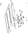
- eine räumliche Explosionsdarstellung der ersten Ausführungsform der erfin dungsgemäßen Verstellvorrichtung mit dazugehörigen wesentlichen Teilen;
- Fig. 3
- in einer Draufsicht die erste Ausführungsform der erfindungsgemäßen Verstellvorrichtung zu Beginn einer Verschiebebewegung des Betätigungselementes;
- Fig. 4
- in einer Draufsicht die erste Ausführungsform der erfindungsgemäßen Verstellvorrichtung mit einem verschobenen Verstellkörper während einer vorwärts gerichteten Verschiebebewegung;
- Fig. 5
- in einer Draufsicht die erste Ausführungsform der erfindungsgemäßen Verstellvorrichtung mit einem verschobenen Verstellkörper zum Zeitpunkt einer rückwärts gerichteten Verschiebebewegung des Betätigungselementes;
- Fig. 6
- in einer Draufsicht die erste Ausführungsform der erfindungsgemäßen Verstellvorrichtung zu Beginn einer Verschiebebewegung des Betätigungselementes zum Einleiten einer rückwärts gerichteten Verschiebebewegung des Verstellkörpers;
- Fig. 7
- in einer Draufsicht die erste Ausführungsform der erfindungsgemäßen Verschiebevorrichtung mit dem in Gegenrichtung verschobenen Verstellkörper;
- Fig. 8
- in einer Draufsicht eine zweite Ausführungsform der erfindungsgemäßen Verstellvorrichtung mit einem unverschobenen Verstellkörper;
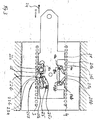
- Fig. 9
- in einer Draufsicht die zweite Ausführungsform der erfindungsgemäßen Verstellvorrichtung mit einem verschobenen Verstellkörper in einer ersten Endstellung; und
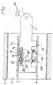
- Fig. 10
- in einer Draufsicht die zweite Ausführungsform der erfindungsgemäßen Verstellvorrichtung mit einem verschobenen Verstellkörper in einer zweiten Endstellung.
- Fig. 1
- in a plan view a first embodiment of the adjustment device according to the invention with an un displaced adjustment body;
- Fig. 2
- a three-dimensional exploded view of the first embodiment of the adjustment device according to the invention with associated essential parts;
- Fig. 3
- in a plan view, the first embodiment of the adjusting device according to the invention at the start of a displacement movement of the actuating element;
- Fig. 4
- in a plan view the first embodiment of the adjustment device according to the invention with a displaced adjustment body during a forward displacement movement;
- Fig. 5
- in a plan view the first embodiment of the adjusting device according to the invention with a displaced adjusting body at the time of a rearward sliding movement of the actuating element;
- Fig. 6
- in a plan view the first embodiment of the adjusting device according to the invention at the beginning of a sliding movement of the actuating element for initiating a rearward sliding movement of the adjusting body;
- Fig. 7
- in a plan view the first embodiment of the displacement device according to the invention with the adjustment body displaced in the opposite direction;
- Fig. 8
- in a plan view, a second embodiment of the adjustment device according to the invention with an unshifted adjustment body;
- Fig. 9
- in a plan view the second embodiment of the adjustment device according to the invention with a displaced adjustment body in a first end position; and
- Fig. 10
- in a plan view the second embodiment of the adjustment device according to the invention with a displaced adjustment body in a second end position.
Fig. 1 zeigt in einer Draufsicht eine ersten Ausführungsform der ratschenartigen Verstellvorrichtung
zum ratschenden Verschieben eines Verstellkörpers gegenüber einem ortsfesten
Basiselement mittels eines länglichen Betätigungselementes mit dem Verstellkörper in mittlerer
Position - also einer Nullstellung - , bei der der Verstellkörper unverschoben gegenüber
dem Basiselement vorliegt. Die erfindungsgemäße ratschenartige Verstellvorrichtung umfasst
den in dem ortsfesten Basiselement 1 verschiebbar angeordneten Verstellkörper 2, der
eine erste Linearverzahnung 3 und eine parallel dazu verlaufende zweite Linearverzahnung
4 an seiner Oberfläche aufweist. 1 shows a top view of a first embodiment of the ratchet-like adjustment device
for ratcheting displacement of an adjustment body compared to a stationary one
Base element by means of an elongated actuating element with the adjusting body in the middle
Position - that is, a zero position - in which the adjustment body is not displaced opposite
the base element is present. The ratchet-like adjustment device according to the invention comprises
the displaceably arranged in the fixed
Sowohl das Basiselement 1 als auch der Verstellkörper 2 und ein Betätigungselement 5 sind
plattenartig ausgebildet, dass heißt sie weisen eine geringe Dicke auf.Both the
Das Betätigungselement 5 ist zwischen der ersten und zweiten Linearverzahnung 3, 4 verschiebbar
angeordnet, indem die Aneinanderreihung der einzelnen Zähne der Linearverzahnungen
als Führungsbegrenzungen für erste und zweite Längsseiten 5a, 5b des Betätigungselementes
5 dienen.The
Da die Linearverzahnungen 3, 4 und das Betätigungselement 5 im wesentlichen gleiche Dicken
aufweisen, kann die Gesamtkonstruktion mittels eines hier nicht gezeigten Abdeckbleches
auf einfache Weise oberseitig abgedeckt werden, um Verschmutzungen und Beeinflussungen
der Funktionsweise der Verstellvorrichtung durch andere Gegenstände zu vermeiden.Since the
Das Betätigungselement 5 weist an seinem einen offenen Ende 6 einen hier nicht gezeigten
Handgriff auf, der dazu dient, das Betätigungselement 5 hin und her beziehungsweise vorund
rückwärts zu bewegen, um eine lineare, schrittweise ratschende Verstellung des Verstellkörpers
2 relativ zu dem ortsfesten Basiselement 1 zu erreichen.The
Das Betätigungselement 5 weist an seiner ersten Längsseite 5a kreisrunde Aussparungen
7a, 7b auf, die voneinander beabstandet sind und zur lagernden Aufnahme eines kreisrundenartigen
Lagerabschnittes von ersten Ratschenelementen 8a, 8b dient. Auf diese Weise
findet eine schwenkbare Lagerung der ersten Ratschenelemente 8a, 8b innerhalb des Betätigungselementes
5 statt.The
Die Ratschenelemente 8a, 8b weisen oberseitig Zapfen 9a, 9b auf, die senkrecht zu der Verschiebebewegung
des Betätigungselementes, die im Bezug auf die Bildebene der Fig. 1
links- und rechtsseitig ausgerichtet ist, sich erstrecken. Die Zapfen 9a, 9b greifen in Ausnehmungen
10a, 10b ein, die innerhalb des ortsfesten Basiselementes, das sich in diesem
Bereich in hier nicht gezeigter Form über die ersten Ratschenelemente erstreckt, angeordnet
sind.The
Die Ausnehmungen 10a, 10b dienen zur Führung der Zapfen 9a, 9b und veranlassen in Abhängigkeit
von ihrem spezifischen Randverlauf vorbestimmte Schwenkbewegungen der ersten
Ratschenelemente 8a, 8b durch Entlanggleiten der Zapfen 9a, 9b entlang des Randes
der Ausnehmungen 10a, 10b.The recesses 10a, 10b serve to guide the
Um ein anhaltendes Einrasten der ersten Ratschenelemente 8a, 8b in die Zähne der ersten
Linearverzahnung 3 sicherzustellen, sind die ersten Ratschenelemente mittels einer Zugfeder
11 federkraftbeaufschlagt. Die Federkraft der Zugfeder 11 bewirkt ein Drücken der Ratschenelemente
8a, 8b gegen die Zähne der ersten Linearverzahnung 3 und wirkt entgegen
einer zum Ausrasten der Ratschenelemente 8a, 8b durchführbaren Schwenkbewegung, indem
die Zugfeder über einen Vorsprung 12, der im Bereich der ersten Längsseite 5a des
Betätigungselementes 5 angeordnet ist, umgelenkt wird.To ensure that the
In einer Ausnehmung 13 entlang der zweiten Längsseite 5b des Betätigungselementes 5
sind zwei zweite Ratschenelemente 14a, 14b angeordnet, die gegen die als Brems- und
Sperrverzahnung wirkende Linearverzahnung 4 gedrückt werden. Die zweiten Ratschenelemente
14a, 14b wirken als Bremsen und sind mittels aus der Bildebene herausragenden
Zapfen 15a, 15b schwenkbar an dem ortsfesten Basiselement 1, das sich in diesem Bereich
über die Bremsen 14a, 14b erstreckt, wie es in dieser Figur allerdings nicht gezeigt wird,
schwenkbar gelagert.In a
Vorteilhaft sind die Bremsen 14a, 14b in einem spitzen Winkel 16a, 16b derart gegenüber
der Linearverzahnung gestellt, dass die eine Bremse 14a entgegen einer vorwärts gerichteten
Verschiebebewegung und die weitere Bremse 14b entgegen einer rückwärts gerichteten
Verschiebebewegung wirken können.The
Um ein Einrasten der Bremsen 14a, 14b in die zweite Linearverzahnung 4 sicherzustellen,
sind die beiden Bremsen mittels einer Zugfeder 17 federkraftbeaufschlagt.In order to ensure that the
Durch Verschieben des Betätigungselementes 5 ist es möglich, rückwärtige Endstücke 18a,
18b der Bremsen 14a, 14b mittel innerhalb der Ausnehmung 13 angeordneten Vorsprünge
19a, 19b in vorbestimmter Weise auszulenken und dadurch ein Ausrasten einer der Bremsen
zu erreichen. Dies führt zu einer Freigabe der zwischen dem Betätigungselement 5 und
dem Verstellkörper 2 bestehenden Arretierung in eine der beiden Verschieberichtungen.By moving the
In Fig. 2 wird nochmals zur Verdeutlichung des Aufbaus der erfindungsgemäßen Verstellvorrichtung
in einer räumlichen Explosionsdarstellung ohne Darstellung des ortsfesten Basiselementes
die Verstellvorrichtung gezeigt. Wie der in Fig. 2 gezeigten Darstellung der Verstellvorrichtung
zu entnehmen ist, sind sowohl der Verstellkörper 2 als auch das Betätigungselement
5 und die ersten und zweiten Ratschenelemente 8a, 8b, 14a, 14b mit einer
geringen Dickenabmessung ausgestatten, so dass die Gesamtdicke der erfindungsgemäßen
Verstellvorrichtung gering ist.In Fig. 2 is again to clarify the structure of the adjusting device according to the invention
in a spatial exploded view without showing the fixed base element
the adjustment device shown. As the illustration of the adjusting device shown in FIG. 2
can be seen, both the adjusting
Hierbei weisen das Betätigungselement 5 und die ersten und zweiten Ratschenelemente 8a,
8b, 14a, 14b die gleiche Dicke auf.The
Der in Fig. 2 wiedergegebenen Darstellung ist deutlich zu entnehmen, dass die Ratschenelemente
oberseitig Zapfen 9a, 9b, 15a, 15b aufweisen, die zum Führen der ersten Ratschenelemente
8a, 8b innerhalb der Ausnehmungen 10a, 10b und zur schwenkbaren Lagerung
der Bremsen 14a, 14b innerhalb des ortsfesten Basiselementes 1 dienen.The illustration shown in FIG. 2 clearly shows that the ratchet elements
have
Fig. 3 zeigt die erfindungsgemäße Verstellvorrichtung zu Beginn eines vorwärts gerichteten
Verstellvorganges. Hierfür wird das Betätigungselement 5 um 2 mm nach links verschoben.
Die Verschiebung des Betätigungselementes gegenüber dem Verstellkörper 2 wird durch
den Pfeil 24 angedeutetFig. 3 shows the adjustment device according to the invention at the beginning of a forward
Adjustment process. For this purpose, the
Auf diese Weise findet vor Beginn der Verschiebung des Verstellkörpers 2 eine vollständige
Einrastung des ersten Ratschenelementes 8b in die erste Linearverzahnung 3, die als Anund
Abtriebsverzahnung dient, statt. Sowohl diese vollständige Einrastung des ersten Ratschenelementes
8b als auch ein Ausrasten des ersten Ratschenelementes 8a werden durch
den Verlauf der Zapfen 9b, 9a entlang des Randes 25 der Ausnehmungen 10b, 10a bestimmt.In this way, a complete takes place before the displacement of the adjusting
Aufgrund der Verschiebung des Betätigungselementes 5 wird das rückwärtige Ende 18a
durch den Vorsprung 19a verschwenkt, wodurch eine Stirnseite 20a der Bremse 14a von
Zähnen 21 der Bremsverzahnung 4 wegbewegt wird. Eine Stirnseite 20b der Bremse 14b
dagegen bleibt weiterhin in Kontakt mit den Zähnen 21.Due to the displacement of the
Durch die Ausrastschwenkbewegung der Bremse 14a wird eine Verschiebung des Verstellkörpers
2 nach links bezogen auf die Bildebene gegenüber dem Basiselement 1 erst möglich,
da zuvor die mit dem Basiselement verbundene Bremse 14a eine Arretierung des Verstellkörpers
2 gegenüber dem Basiselement 1 bewirkte.The disengaging pivoting movement of the
In Fig. 4 wird in eine Draufsicht die erfindungsgemäße Verstellvorrichtung am Ende des vorwärts
gerichteten Verstell- beziehungsweise Verschiebevorganges dargestellt. Das Betätigungselement
5 ist nun insgesamt um beispielsweise 10 mm nach links verschoben, während
der schlittenartig ausgebildete Verstellkörper 2 um beispielsweise 8 mm eine Linksverschiebung
beziehungsweise eine vorwärts gerichtete Verschiebung erfahren hat.In Fig. 4 is a plan view of the adjustment device according to the invention at the end of the forward
directed adjustment or displacement process shown. The
Der Unterschied bei den beiden Verschiebewegen in der Größenordnung von etwa 2 mm
entsteht durch die anfängliche Verschiebung des Betätigungselementes 5 gegenüber dem
Verstellkörper 2, wie es in Fig. 3 gezeigt wird. Diese anfängliche Verschiebung des Betätigungselementes
5 um beispielsweise 2 mm dient für die gleitende Ein- und Ausrastung der
ersten Ratschenelemente 8a, 8b sowie der Ausrastung der Bremse 14a. Ein derartig gleitender
Ein- und Ausrastvorgang bewirkt eine Schonung der einzelnen Zähne 22 der Ratschenelemente
und der einzelnen An- und Abtriebszähne der ersten Linearverzahnung 3 bei einem
Zusammenspiel derjenigen.The difference in the two displacement paths in the order of about 2 mm
arises from the initial displacement of the
Zudem wird ein gleitendes Ein- und Ausrasten durch ein Zahnprofil der Zähne 22 der ersten
Ratschenelemente gefördert, welches sich dadurch auszeichnet, dass die Zähne auf der
einen Seite eine abgeschrägte Flanke 22a und auf der anderen Seite eine senkrecht zu der
Verschiebebewegung des Betätigungselements ausgerichtete Flanke 22b aufweisen.In addition, a sliding engagement and disengagement by a tooth profile of the
Für die entgegengesetzte Verschiebebewegung des Betätigungselementes 5 sind an dem
anderen ersten Ratschenelement 8b die Flanken in umgekehrter Reihenfolge angeordnet,
wie es aus den Bezugszeichen 23a und 23b hervorgeht.For the opposite displacement movement of the
Die Beendigung des vorwärts gerichteten Verschiebevorganges wird durch den Zapfen 9b,
der entlang eines Randes 25 der Ausnehmung 10b von dem Abschnitt 25a über den Abschnitt
25b zu dem Abschnitt 25c gleitet, bestimmt. Der Abschnitt 25c dient als Anschlag für
den Zapfen 9b und verhindert eine weitere vorwärts gerichtete Verschiebung des Verstellkörpers
2 und des Betätigungselementes 5 gegenüber dem ortsfesten Basiselement 1, da
die Ausnehmung 10b innerhalb des ortsfesten Basiselementes angeordnet ist.The end of the forward shifting process is achieved by the pin 9b,
that along an
Gleichzeitig findet eine ausrastende Schwenkbewegung des ersten Ratschenelementes 8a
durch Führung des Zapfens 9a innerhalb des Randabschnittes 25a des Randes 25 der Ausnehmung
10a statt.At the same time there is a disengaging pivoting movement of the
Wird nun das Betätigungselement 5 gemäß der Abbildung in Fig. 5 zurückgeschoben, also
im Bezug auf die Bildebene nach rechts verschoben, so findet eine Relativverschiebung des
Betätigungselementes 5 gegenüber dem Verstellkörper 2 statt, da eine Mitnahme des Verstellkörpers
2 durch das Betätigungselement aufgrund der ausgerasteten Stellung des ersten
Ratschenelementes 8a nicht möglich ist. Demzufolge kann das Betätigungselement 5 um
insgesamt 10 mm nach rechts gegenüber dem Verstellkörper 2 verschoben werden.If the
In Fig. 5 wird in einer Draufsicht die erfindungsgemäße Verstellvorrichtung mit einem zurückbewegten
Betätigungselement 5 dargestellt. Das Betätigungselement 5 nimmt wiederum
eine Nullstellung gegenüber dem ortsfesten Basiselement ein und bewirkt durch Verschiebung
des Vorsprungs 19a ein Einrasten der Bremse 14a, welches zu einer Sperrstellung des
Verstellkörpers 2 gegenüber dem ortsfesten Basiselement 1 führt.In Fig. 5, the adjustment device according to the invention is moved back with a
Ebenso sind die ersten Ratschenelemente 8a, 8b wiederum in nicht vollständig eingerasteter
Position durch Wirkung der Feder 11.Likewise, the
In dieser Nullstellung kann beispielsweise der Fahrzeugsitz, dessen Sitzplatte mit dem Verstellkörper
2 verbunden ist, benutzt werden, ohne dass eine ungewollte Verschiebung der
Sitzplatte gegenüber dem ortsfesten Basiselement stattfinden kann. Alternativ kann durch
eine vorwärts gerichtete Verschiebebewegung des Betätigungselementes 5 ein weiterer Verstellzyklus
eingeleitet werden, um die Sitzplatte mit dem Verstellkörper 2 noch weiter zu verschieben. In this zero position, for example, the vehicle seat, the seat plate with the
In Fig. 6 wird in einer Draufsicht die erfindungsgemäße Verstellvorrichtung zu Beginn eines
rückwärts gerichteten Verstellvorganges, also einer Verschiebung des Verstellkörpers 2 in
die Gegenrichtung gezeigt. Hierfür wird das Betätigungselement 5, wie es durch den Pfeil 26
angedeutet wird, um 2 mm nach rechts im Bezug auf die Bildebene verschoben, woraufhin
die Bremse 14b aufgrund der Vorsprungsbewegung des Vorsprunges 19b ausrastet.6 is a top view of the adjustment device according to the invention at the beginning of a
backward adjustment process, that is, a displacement of the
Ebenso rastet das erste Ratschenelement 8b aufgrund der Führung seines Zapfens 9b entlang
der Randabschnitte 25a und 25b aus der Linearverzahnung 3 aus. Zeitgleich rastet das
erste Ratschenelement 8a aufgrund der Führung seines Zapfens 9a entlang des Randabschnittes
25b in die Linearverzahnung 3 ein.Likewise, the
In Fig. 7 wird in einer Draufsicht die Verstellvorrichtung nach Beendigung eines rückwärts
gerichteten Verschiebevorganges gezeigt, wobei in diesem Fall insgesamt drei Verschiebebeziehungsweise
Verstellzyklen bei dazwischen liegendem nach vorne Verschieben des
Betätigungselementes 5 durchgeführt wurden. Dies entspricht einer Verschiebung des Verstellkörpers
2 um insgesamt 24 mm, wie es durch das Bezugszeichen 27 wiedergegeben
wird.In Fig. 7 is a top view of the adjustment device after completing a reverse
directed shifting process shown, in this case a total of three shift or
Adjustment cycles with the intermediate shifting forward
Actuator 5 were performed. This corresponds to a displacement of the
In den Figuren 8-10 wird eine zweite Ausführungsform der erfindungsgemäßen Verschiebevorrichtung
gezeigt. Die zweite Ausführungsform unterscheidet sich von der ersten Ausführungsform
darin, dass Endzähne 26a an Enden der ersten Linearverzahnung 3 derart
ausgebildet sind, dass ihre Längenabmessungen in Bezug auf die Verschieberichtung doppelt
so groß wie die Längenabmessungen der restlichen zwischen den Endzähnen 26a angeordneten
Zähne 26 sind. Auf die Weise wird, sobald sich der Verstellkörper in einer vorbestimmbaren
Endstellung befindet, wie sie in den Figuren 9 und 10 für eine vorwärts und
rückwärts gerichtete Verschiebung gezeigt wird, das als Antrieb wirkende erste Ratschenelement
8a, 8b vollständig ausser Eingriff bezüglich der Linearverzahnung 3 gebracht. Dies
hat zur Folge, dass kein weiterer Antrieb des Verstellkörpes 2 stattfinden kann. Der schlittenartige
Verstellkörper 2 kann somit nicht mehr bewegt werden. Eine derartige automatische
Blockierung der gesamten Verstellvorrichtung verhindert auf einfache Weise ein ungewolltes
zu weites verschieben des Verstellkörpers 2 gegenüber dem ortsfesten Basiselement
1. FIGS. 8-10 show a second embodiment of the displacement device according to the invention
shown. The second embodiment differs from the first embodiment
in that end teeth 26a at ends of the first
Für gleiche und gleichwirkende Teile sind in den Figuren die gleichen Bezugszeichen verwendet worden.The same reference numerals are used in the figures for the same and equivalent parts Service.
Sämtliche Bauteile sind einzeln und in Kombination als erfindungswesentlich anzusehen. Abwandlungen hiervon sind dem Fachmann geläufig. Beispielsweise kann das längliche Betätigungselement als Blattfederstahlblech ausgebildet sein, wobei die ersten Ratschenelemente und vorzugsweise auch die zweiten Ratschenelemente als federnde Arme an beiden Längsseiten des Betätigungselementes angeordnet sind und ebenso aus Blattfederstahl bestehen. Die Ratschenelemente und das Betätigungselement sind einteilig ausgebildet. Durch Verschieben der federblattartig ausgebildeten Ratschenelemente zusammen mit dem Betätigungselement über einen mit dem ortsfesten Basiselement verbundenen Vorsprung, der zwischen den Ratschenelementen und den Linearverzahnungen jeweils angeordnet ist, können die in ihrer Ruhestellung in die Linearverzahnung eingreifenden Ratschenelemente aus der Eingriffsposition in eine ausgerückte Stellung einzeln gebracht werden. Auf diese Weise ist das wahlweise Ausrücken der bezüglich der Verschiebebewegung des Betätigungselements entweder vorwärts gerichteten oder rückwärts gerichteten Ratschenelemente oder das gemeinsame Einrücken sämtlicher Ratschenelemente möglich. Die Linearverzahnung ist wiederum auf dem Verstellkörper angeordnet.All components are to be regarded individually and in combination as essential to the invention. Modifications to this are familiar to the person skilled in the art. For example, the elongate actuator be designed as a leaf spring steel sheet, the first ratchet elements and preferably also the second ratchet elements as resilient arms on both Longitudinal sides of the actuating element are arranged and also consist of leaf spring steel. The ratchet elements and the actuating element are formed in one piece. By Moving the ratchet elements designed like a spring leaf together with the actuating element via a projection connected to the stationary base element, the is arranged between the ratchet elements and the linear teeth, respectively the ratchet elements engaging in the linear toothing in their rest position the engaged position can be brought individually into a disengaged position. In this way is the optional disengagement of the actuating element with respect to the displacement movement either forward or backward ratchet elements, or the common engagement of all ratchet elements possible. The linear toothing is again arranged on the adjustment body.
- 11
- ortsfestes Basiselementstationary base element
- 22
- Verstellkörperadjusting body
- 33
- erste Linearverzahnungfirst linear toothing
- 44
- zweite Linearverzahnungsecond linear toothing
- 55
- Betätigungselementactuator
- 5a, 5b5a, 5b
- erste und zweite Längsseiten des Betätigungselementesfirst and second long sides of the actuating element
- 66
- Ende des BetätigungselementesEnd of the actuator
- 7a, 7b7a, 7b
- kreisrunde Aussparungencircular recesses
- 8a, 8b8a, 8b
- erste Ratschenelementefirst ratchet elements
- 9a, 9b9a, 9b
- Zapfen spigot
- 10a, 10b10a, 10b
- Ausnehmungenrecesses
- 1111
- Zugfedermainspring
- 1212
- Vorsprunghead Start
- 1313
- Ausnehmungrecess
- 14a, 14b14a, 14b
- Bremsenbrakes
- 15a, 15b15a, 15b
- Schwenkzapfen der BremsenBrake pivots
- 16a,16b16a, 16b
- spitze Winkelacute angle
- 1717
- Zugfedermainspring
- 18a, 18b18a, 18b
- Rückwärtige Enden der BremsenRear ends of the brakes
- 19a, 19b19a, 19b
- Vorsprünge am BetätigungselementProjections on the actuator
- 20a, 20b20a, 20b
- Stirnseiten der BremsenFront of the brakes
- 21a, 21b21a, 21b
- Abgeschrägte Flanken der ZähneBeveled flanks of the teeth
- 2121
- Zähne der zweiten LinearverzahnungTeeth of the second linear toothing
- 2222
- Zähne der ersten RatschenelementeTeeth of the first ratchet elements
- 22a, 23a22a, 23a
- abgeschrägte Flanken der Zähnebeveled flanks of the teeth
- 22b, 23b22b, 23b
-
senkrechte Flanken der Zähne 22vertical flanks of
teeth 22 - 2424
- Verschieberichtungdisplacement direction
- 2525
- Randverlauf der AusnehmungenEdge course of the recesses
- 25a25a
- erster Randverlaufsabschnittfirst edge section
- 25b25b
- zweiter Randverlaufsabschnittsecond edge section
- 25c25c
- dritter Randverlaufsabschnittthird margin section
- 2626
- Zähne der ersten LinearverzahnungTeeth of the first linear toothing
- 26a26a
- Endzähne der ersten LinearverzahnungEnd teeth of the first linear toothing
Claims (16)
gekennzeichnet durch
mindestens zwei an dem ortsfesten Basiselement (1) schwenkbar gelagerte zweite Ratschenelemente (14a, 14b), die zum Sperren einer Verschiebebewegung des Verstellkörpers (2) gegenüber dem ortsfesten Basiselement (1) in die zweite als Sperrund Bremsverzahnung wirkende Linearverzahnung (4) einrastbar sind.Ratchet-like adjustment device for ratcheting displacement of an adjustment body (2) relative to a stationary base element (1) by means of an elongated actuation element (5), the actuation element (5) being displaceable along linear gears (4) attached to the adjustment body (2) on both sides of the actuation element and can be snapped into the first linear toothing (3) acting as input and output toothing by means of first ratchet elements (8a, 8b),
marked by
at least two second ratchet elements (14a, 14b) pivotably mounted on the fixed base element (1), which can be snapped into the second linear toothing (4) acting as locking and braking toothing in order to block a displacement movement of the adjusting body (2) relative to the fixed base element (1).
dadurch gekennzeichnet,dass
jedes zweite Ratschenelement (14a, 14b) mittels mindestens eines entlang einer Längsseite (5b) des Betätigungselements (5) ausgebildeten Vorsprungs (19a, 19b) durch Verschieben des Betätigungselements (5) schwenkend ausrastbar ist.Ratchet-like adjusting device according to claim 1,
characterized in that
each second ratchet element (14a, 14b) can be pivotally disengaged by moving the actuating element (5) by means of at least one projection (19a, 19b) formed along a long side (5b) of the actuating element (5).
dadurch gekennzeichnet,dass
die zweiten Ratschenelemente (14a, 14b) derart ausgebildet sind, dass sie im eingerasteten Zustand ausgehend von einem Lagerzapfen (15a, 15b) zur schwenkbaren Lagerung der Ratschenelemente (14a, 14b) in einem spitzen Winkel (16a, 16b) zur Verlaufsrichtung der zweiten Linearverzahnung (4) stehen und mit ihrer Stirnseite (20a, 20b) Zähne (21) die zweite Linearverzahnung (4) berühren. Ratchet-like adjusting device according to claim 1 or 2,
characterized in that
the second ratchet elements (14a, 14b) are designed in such a way that, in the engaged state, they start from a bearing journal (15a, 15b) for pivotably mounting the ratchet elements (14a, 14b) at an acute angle (16a, 16b) to the direction of the second linear toothing (4) stand and with their end face (20a, 20b) teeth (21) touch the second linear toothing (4).
dadurch gekennzeichnet,dass
die spitzen Winkel (16a, 16b) der beiden zweiten Ratschenelemente (14a, 14b) derart angeordnet sind, dass eines der Ratschenelemente (14a) entgegen einer vorwärts gerichteten Verschiebebewegung und das weitere Ratschenelement (14b) entgegen einer rückwärts gerichteten Verschiebebewegung des Verstellkörpers (2) in Bezug auf das Basiselement (1) wirken.Ratchet-like adjusting device according to claim 3,
characterized in that
the acute angles (16a, 16b) of the two second ratchet elements (14a, 14b) are arranged in such a way that one of the ratchet elements (14a) opposes a forward displacement movement and the further ratchet element (14b) opposes a rearward displacement movement of the adjustment body (2) act in relation to the base element (1).
dadurch gekennzeichnet,dass
die zweiten Ratschenelemente (14a, 14b) mittels mindestens einer die Ratschenelemente (14a, 14b) verbindenden Zugfeder (17) unter Federkraftbeaufschlagung in die zweite Linearverzahnung (4) einrastbar sind.Ratchet-like adjusting device according to one of the preceding claims,
characterized in that
the second ratchet elements (14a, 14b) can be snapped into the second linear toothing (4) by means of at least one tension spring (17) connecting the ratchet elements (14a, 14b) under spring force.
dadurch gekennzeichnet,dass
die ersten Ratschenelemente (8a, 8b) in dem Betätigungselement (5) um eine senkrecht zur Verschiebebewegung ausgerichtete fiktive Schwenkachse schwenkbar gelagert sind.Ratchet-like adjusting device according to one of the preceding claims,
characterized in that
the first ratchet elements (8a, 8b) are mounted in the actuating element (5) so as to be pivotable about a fictitious pivot axis oriented perpendicular to the displacement movement.
dadurch gekennzeichnet, dass
das längliche Betätigungselement (5) an einer weiteren Längsseite (5a) voneinander beabstandet mit zwei kreisrunden Aussparungen (7a, 7b) ausgebildet ist, in welche jeweils ein erstes Ratschenelement (8a, 8b) mit einem kreisrundenartigen Lagerabschnitt schwenkbeweglich gelagert ist. Ratchet-like adjusting device according to one of the preceding claims,
characterized in that
the elongated actuating element (5) is formed on a further longitudinal side (5a) spaced apart from one another with two circular recesses (7a, 7b), in each of which a first ratchet element (8a, 8b) with a circular bearing section is pivotally mounted.
dadurch gekennzeichnet,dass
das ortsfeste Basiselement (1) Ausnehmungen (10a, 10b) aufweist, in welchen jeweils ein auf jedem ersten Ratschenelement (8a, 8b) angeordneter Zapfen (9a, 9b) geführt wird, wobei die Zapfen (9a, 9b) orthogonal zur Verschieberichtung des Betätigungselements (5) ausgerichtet sind.Ratchet-like adjusting device according to one of the preceding claims,
characterized in that
the stationary base element (1) has recesses (10a, 10b) into which a pin (9a, 9b) arranged on each first ratchet element (8a, 8b) is guided, the pin (9a, 9b) being orthogonal to the direction of displacement of the actuating element (5) are aligned.
dadurch gekennzeichnet,dass
die Ausnehmungen (10a, 10b) jeweils einen derartigen Randverlauf (25) aufweisen, dass mittels eines Entlanggleitens der Zapfen (9a, 9b) an den Rändern (25) während der Verschiebebewegung des Betätigungselements (5) Schwenkbewegungen der ersten Ratschenelemente (8a, 8b) durchgeführt werden.Ratchet-like adjusting device according to claim 8,
characterized in that
the recesses (10a, 10b) each have an edge profile (25) such that by sliding the pins (9a, 9b) along the edges (25) during the displacement movement of the actuating element (5), pivoting movements of the first ratchet elements (8a, 8b) be performed.
dadurch gekennzeichnet, dass
der Randverlauf (25) einen Anschlag (25c) für den sich darin bewegenden Zapfen (9a, 9b) für die Verschiebebewegung des Betätigungselementes (5) mit dem Verstellkörper (2) gegenüber dem ortsfesten Basiselement (1) darstellt.Ratchet-like adjusting device according to claim 9,
characterized in that
the edge profile (25) represents a stop (25c) for the pin (9a, 9b) moving therein for the displacement movement of the actuating element (5) with the adjusting body (2) relative to the stationary base element (1).
dadurch gekennzeichnet,dass
die ersten Ratschenelemente (8a, 8b) mittels mindestens einer über einen Vorsprung (12) der weiteren Längsseite (5a) des Betätigungselements (5) umgelenkten Zugfeder (11) gegen die erste Linearverzahnung (3) in Abhängigkeit von der Position der Zapfen (9a, 9b) innerhalb der Ausnehmungen (10a, 10b) drückbar sind.Ratchet-like adjusting device according to one of claims 8-10,
characterized in that
the first ratchet elements (8a, 8b) by means of at least one tension spring (11) deflected via a projection (12) on the further longitudinal side (5a) of the actuating element (5) against the first linear toothing (3) as a function of the position of the pins (9a, 9b) can be pressed within the recesses (10a, 10b).
dadurch gekennzeichnet,dass
das Zahnprofil der Zähne (22) der ersten Ratschenelemente (8a, 8b) in Bezug auf die Verschieberichtung auf der einen Seite abgeschrägte Flanken (22a) und auf der anderen Seite senkrechte Flanken (22b) aufweist. Ratchet-like adjusting device according to one of the preceding claims,
characterized in that
the tooth profile of the teeth (22) of the first ratchet elements (8a, 8b) has beveled flanks (22a) on one side with respect to the direction of displacement and vertical flanks (22b) on the other side.
dadurch gekennzeichnet, dass
an Enden der ersten Linearverzahnung (3) Endzähne (26a) angeordnet sind, deren Längenabmessungen in Bezug auf die Verschieberichtung größer als Längenabmessungen der restlichen Zähne (26) der ersten Linearverzahnung (3) sind.Ratchet-like adjusting device according to one of the preceding claims,
characterized in that
End teeth (26a) are arranged at the ends of the first linear toothing (3), the length dimensions of which in relation to the direction of displacement are greater than the length dimensions of the remaining teeth (26) of the first linear toothing (3).
dadurch gekennzeichnet,dass
die Längenabmessungen der Endzähne (26a) den zweifachen Längenabmessungen der restlichen Zähne (26) entsprechen.Ratchet-like adjusting device according to claim 13,
characterized in that
the length dimensions of the end teeth (26a) correspond to twice the length dimensions of the remaining teeth (26).
dadurch gekennzeichnet, dass
die ersten und zweiten Linearverzahnungen (3,4) zugleich als Führungsbegrenzungen für das verschiebbare Betätigungselement (5) dienen.Ratchet-like adjusting device according to one of the preceding claims,
characterized in that
the first and second linear gears (3, 4) also serve as guide limits for the displaceable actuating element (5).
dadurch gekennzeichnet, dass
das Betätigungselement (5) endseitig (6) mit einem Bedienungselement ausgestattet ist.Ratchet-like adjusting device according to one of the preceding claims,
characterized in that
the actuating element (5) is equipped at the end (6) with an operating element.
Applications Claiming Priority (4)
| Application Number | Priority Date | Filing Date | Title |
|---|---|---|---|
| DE10318939 | 2003-04-26 | ||
| DE10318939 | 2003-04-26 | ||
| DE102004011054A DE102004011054B4 (en) | 2003-04-26 | 2004-03-06 | Ratchet-like adjusting device |
| DE102004011054 | 2004-03-06 |
Publications (3)
| Publication Number | Publication Date |
|---|---|
| EP1470951A2 true EP1470951A2 (en) | 2004-10-27 |
| EP1470951A3 EP1470951A3 (en) | 2006-04-05 |
| EP1470951B1 EP1470951B1 (en) | 2007-10-24 |
Family
ID=32963539
Family Applications (1)
| Application Number | Title | Priority Date | Filing Date |
|---|---|---|---|
| EP04008811A Expired - Lifetime EP1470951B1 (en) | 2003-04-26 | 2004-04-14 | Ratchet adjusting device |
Country Status (4)
| Country | Link |
|---|---|
| US (1) | US7357051B2 (en) |
| EP (1) | EP1470951B1 (en) |
| CN (1) | CN100463815C (en) |
| DE (1) | DE502004005308D1 (en) |
Families Citing this family (6)
| Publication number | Priority date | Publication date | Assignee | Title |
|---|---|---|---|---|
| CN101670796B (en) * | 2008-09-10 | 2011-11-16 | 宝钜实业股份有限公司 | Child safety seat |
| DE102010035430B4 (en) | 2010-08-26 | 2014-03-27 | Johnson Controls Gmbh | Adjustment device, in particular for a vehicle seat |
| US9616785B2 (en) * | 2014-01-09 | 2017-04-11 | PAC Seating Systems, Inc. | Infinitely vertically adjustable drop down armrest mechanism |
| US10426269B1 (en) * | 2018-04-30 | 2019-10-01 | Buzz Seating, Inc. | Chair with appendage accommodations |
| KR102613446B1 (en) * | 2018-12-20 | 2023-12-13 | 현대트랜시스 주식회사 | Seat track mechanism for vehicle seat |
| US11708011B2 (en) | 2021-03-05 | 2023-07-25 | Camaco, Llc. | Reinforced track assembly for vehicle seat |
Citations (1)
| Publication number | Priority date | Publication date | Assignee | Title |
|---|---|---|---|---|
| DE10039501A1 (en) | 2000-08-12 | 2002-02-28 | Grammer Ag | Adjusting means |
Family Cites Families (11)
| Publication number | Priority date | Publication date | Assignee | Title |
|---|---|---|---|---|
| US4012158A (en) * | 1975-09-15 | 1977-03-15 | Harper Henry J | Adjustable seat-back mechanism |
| US4451084A (en) * | 1981-12-14 | 1984-05-29 | Simmons Universal Corporation | Backrest height adjustment for office chair |
| US4639039A (en) * | 1985-09-10 | 1987-01-27 | Milsco Manufacturing Company | Height adjustment mechanism for chair backrest |
| US5324096A (en) * | 1992-03-02 | 1994-06-28 | Hon Industries Inc. | Adjustable height chair arm |
| DE4321720C2 (en) * | 1993-06-30 | 2001-08-16 | Keiper Gmbh & Co | Locking system |
| IT239565Y1 (en) * | 1995-03-21 | 2001-03-05 | Miotto Internat Company | HEIGHT ADJUSTMENT DEVICE FOR A CHAIR BACKREST |
| US5586809A (en) * | 1995-08-04 | 1996-12-24 | Herman Miller, Inc. | Height adjustment mechanism for a chair backrest |
| US5664842A (en) * | 1996-05-24 | 1997-09-09 | Shin Yeh Enterprise Co., Ltd. | Height-adjustable armrest unit for a chair |
| US5695249A (en) * | 1996-06-24 | 1997-12-09 | Lotfi; Mehdian | Height adjustment mechanism for chair components |
| AUPP725498A0 (en) * | 1998-11-23 | 1998-12-17 | Klasse Pty Ltd | Back support improvement |
| US6533355B2 (en) * | 2001-03-28 | 2003-03-18 | Haworth, Inc. | Height-adjustment mechanism for a chair |
-
2004
- 2004-04-14 DE DE502004005308T patent/DE502004005308D1/en not_active Expired - Lifetime
- 2004-04-14 EP EP04008811A patent/EP1470951B1/en not_active Expired - Lifetime
- 2004-04-19 CN CNB2004100367549A patent/CN100463815C/en not_active Expired - Lifetime
- 2004-04-20 US US10/827,894 patent/US7357051B2/en active Active
Patent Citations (1)
| Publication number | Priority date | Publication date | Assignee | Title |
|---|---|---|---|---|
| DE10039501A1 (en) | 2000-08-12 | 2002-02-28 | Grammer Ag | Adjusting means |
Also Published As
| Publication number | Publication date |
|---|---|
| DE502004005308D1 (en) | 2007-12-06 |
| US20040221679A1 (en) | 2004-11-11 |
| CN100463815C (en) | 2009-02-25 |
| EP1470951A3 (en) | 2006-04-05 |
| US7357051B2 (en) | 2008-04-15 |
| EP1470951B1 (en) | 2007-10-24 |
| CN1550372A (en) | 2004-12-01 |
Similar Documents
| Publication | Publication Date | Title |
|---|---|---|
| DE102007049032B4 (en) | Pliers | |
| DE102009059159B3 (en) | Steering column for motor vehicle, has casing unit that is pretensioned by bending wire with respect to support part when unit is moved parallel to longitudinal axis of steering shaft toward vehicle front | |
| EP1747117B1 (en) | Blind system comprising a braked sliding element | |
| DE102015225488B3 (en) | Adjustable steering column for motor vehicles with energy absorption device | |
| EP1989960B1 (en) | Detent fitting | |
| DE102006009976A1 (en) | Radial adjustment mechanism for use in vehicle seat assembly has pawl forming pawl axis is movably arranged between guides on one disk element with outer end with toothed segment that can lock into teeth on other disk element | |
| EP2956274B1 (en) | Detachable blocking device, in particular on a clamping tool | |
| DE10144063A1 (en) | Parking lock for automatic gear has locking ring with pawl fitting into holes, selector lever, rollers on end of rods system, guide-plate with horizontal wall and side wall | |
| DE3038565C2 (en) | Stapler | |
| EP1180737A2 (en) | Adjustment device | |
| DE102010029051B4 (en) | Stop arrangement for swiveling body components | |
| EP1470951B1 (en) | Ratchet adjusting device | |
| EP1415833A2 (en) | Guide rail, in particular for a roller blind in motor vehicle | |
| DE19854943B4 (en) | Pressing tool for connection to a drive | |
| CH688023A5 (en) | Binding mechanism between a shoe and a Sportgeraet | |
| DE102004013066A1 (en) | Clamping and spreading device | |
| DE2253732C3 (en) | Device for adjusting the output member of a motion gear | |
| DE102004011054B4 (en) | Ratchet-like adjusting device | |
| WO2014135145A1 (en) | Locking device for a rail guide for a vehicle seat and rail guide | |
| DE102006013108B4 (en) | Clamping tool, in particular tension clamp, vice or Spreizzwinge | |
| DE3304593A1 (en) | ADJUSTMENT AND CENTERING DEVICE FOR SERVO BRAKES | |
| DE102010045423A1 (en) | Locking device for e.g. jacket tube of motor car, has position unit enabling fixation of jacket tube and guide tube, and clamping strip positioned in clamping area between clamping adapter and pressure piece | |
| EP0318720B1 (en) | Automatic length adjusting device of a bowden cable | |
| DE3248053A1 (en) | Releasable door-handle spindle fastening adjustable for different door thicknesses | |
| DE102018115924A1 (en) | chair |
Legal Events
| Date | Code | Title | Description |
|---|---|---|---|
| PUAI | Public reference made under article 153(3) epc to a published international application that has entered the european phase |
Free format text: ORIGINAL CODE: 0009012 |
|
| AK | Designated contracting states |
Kind code of ref document: A2 Designated state(s): AT BE BG CH CY CZ DE DK EE ES FI FR GB GR HU IE IT LI LU MC NL PL PT RO SE SI SK TR |
|
| AX | Request for extension of the european patent |
Extension state: AL HR LT LV MK |
|
| 17P | Request for examination filed |
Effective date: 20050311 |
|
| PUAL | Search report despatched |
Free format text: ORIGINAL CODE: 0009013 |
|
| AK | Designated contracting states |
Kind code of ref document: A3 Designated state(s): AT BE BG CH CY CZ DE DK EE ES FI FR GB GR HU IE IT LI LU MC NL PL PT RO SE SI SK TR |
|
| AX | Request for extension of the european patent |
Extension state: AL HR LT LV MK |
|
| GRAP | Despatch of communication of intention to grant a patent |
Free format text: ORIGINAL CODE: EPIDOSNIGR1 |
|
| AKX | Designation fees paid |
Designated state(s): DE FR GB IT TR |
|
| GRAS | Grant fee paid |
Free format text: ORIGINAL CODE: EPIDOSNIGR3 |
|
| GRAA | (expected) grant |
Free format text: ORIGINAL CODE: 0009210 |
|
| AK | Designated contracting states |
Kind code of ref document: B1 Designated state(s): DE FR GB IT TR |
|
| REG | Reference to a national code |
Ref country code: GB Ref legal event code: FG4D Free format text: NOT ENGLISH |
|
| REF | Corresponds to: |
Ref document number: 502004005308 Country of ref document: DE Date of ref document: 20071206 Kind code of ref document: P |
|
| GBT | Gb: translation of ep patent filed (gb section 77(6)(a)/1977) |
Effective date: 20080130 |
|
| ET | Fr: translation filed | ||
| PLBE | No opposition filed within time limit |
Free format text: ORIGINAL CODE: 0009261 |
|
| STAA | Information on the status of an ep patent application or granted ep patent |
Free format text: STATUS: NO OPPOSITION FILED WITHIN TIME LIMIT |
|
| 26N | No opposition filed |
Effective date: 20080725 |
|
| PGFP | Annual fee paid to national office [announced via postgrant information from national office to epo] |
Ref country code: GB Payment date: 20140423 Year of fee payment: 11 |
|
| PGFP | Annual fee paid to national office [announced via postgrant information from national office to epo] |
Ref country code: FR Payment date: 20140416 Year of fee payment: 11 |
|
| GBPC | Gb: european patent ceased through non-payment of renewal fee |
Effective date: 20150414 |
|
| PG25 | Lapsed in a contracting state [announced via postgrant information from national office to epo] |
Ref country code: GB Free format text: LAPSE BECAUSE OF NON-PAYMENT OF DUE FEES Effective date: 20150414 |
|
| REG | Reference to a national code |
Ref country code: FR Ref legal event code: ST Effective date: 20151231 |
|
| PG25 | Lapsed in a contracting state [announced via postgrant information from national office to epo] |
Ref country code: FR Free format text: LAPSE BECAUSE OF NON-PAYMENT OF DUE FEES Effective date: 20150430 |
|
| PGFP | Annual fee paid to national office [announced via postgrant information from national office to epo] |
Ref country code: IT Payment date: 20160422 Year of fee payment: 13 Ref country code: TR Payment date: 20160405 Year of fee payment: 13 |
|
| PG25 | Lapsed in a contracting state [announced via postgrant information from national office to epo] |
Ref country code: IT Free format text: LAPSE BECAUSE OF NON-PAYMENT OF DUE FEES Effective date: 20170414 |
|
| PG25 | Lapsed in a contracting state [announced via postgrant information from national office to epo] |
Ref country code: TR Free format text: LAPSE BECAUSE OF NON-PAYMENT OF DUE FEES Effective date: 20170414 |
|
| PGFP | Annual fee paid to national office [announced via postgrant information from national office to epo] |
Ref country code: DE Payment date: 20230418 Year of fee payment: 20 |
|
| REG | Reference to a national code |
Ref country code: DE Ref legal event code: R071 Ref document number: 502004005308 Country of ref document: DE |