EP1470805A1 - Mesureur de taille à utilisation simplifiée - Google Patents
Mesureur de taille à utilisation simplifiée Download PDFInfo
- Publication number
- EP1470805A1 EP1470805A1 EP04290750A EP04290750A EP1470805A1 EP 1470805 A1 EP1470805 A1 EP 1470805A1 EP 04290750 A EP04290750 A EP 04290750A EP 04290750 A EP04290750 A EP 04290750A EP 1470805 A1 EP1470805 A1 EP 1470805A1
- Authority
- EP
- European Patent Office
- Prior art keywords
- pointer
- slide
- main body
- implant
- opposite
- Prior art date
- Legal status (The legal status is an assumption and is not a legal conclusion. Google has not performed a legal analysis and makes no representation as to the accuracy of the status listed.)
- Granted
Links
- 239000007943 implant Substances 0.000 claims abstract description 27
- 210000000689 upper leg Anatomy 0.000 claims description 10
- 239000000523 sample Substances 0.000 claims description 9
- 238000002271 resection Methods 0.000 description 4
- 210000000988 bone and bone Anatomy 0.000 description 3
- 238000000034 method Methods 0.000 description 3
- 230000006978 adaptation Effects 0.000 description 1
- 238000001727 in vivo Methods 0.000 description 1
- 238000005259 measurement Methods 0.000 description 1
Images

Classifications
-
- A—HUMAN NECESSITIES
- A61—MEDICAL OR VETERINARY SCIENCE; HYGIENE
- A61F—FILTERS IMPLANTABLE INTO BLOOD VESSELS; PROSTHESES; DEVICES PROVIDING PATENCY TO, OR PREVENTING COLLAPSING OF, TUBULAR STRUCTURES OF THE BODY, e.g. STENTS; ORTHOPAEDIC, NURSING OR CONTRACEPTIVE DEVICES; FOMENTATION; TREATMENT OR PROTECTION OF EYES OR EARS; BANDAGES, DRESSINGS OR ABSORBENT PADS; FIRST-AID KITS
- A61F2/00—Filters implantable into blood vessels; Prostheses, i.e. artificial substitutes or replacements for parts of the body; Appliances for connecting them with the body; Devices providing patency to, or preventing collapsing of, tubular structures of the body, e.g. stents
- A61F2/02—Prostheses implantable into the body
- A61F2/30—Joints
- A61F2/46—Special tools for implanting artificial joints
- A61F2/4657—Measuring instruments used for implanting artificial joints
-
- A—HUMAN NECESSITIES
- A61—MEDICAL OR VETERINARY SCIENCE; HYGIENE
- A61B—DIAGNOSIS; SURGERY; IDENTIFICATION
- A61B17/00—Surgical instruments, devices or methods
- A61B17/14—Surgical saws
- A61B17/15—Guides therefor
- A61B17/154—Guides therefor for preparing bone for knee prosthesis
- A61B17/155—Cutting femur
-
- A—HUMAN NECESSITIES
- A61—MEDICAL OR VETERINARY SCIENCE; HYGIENE
- A61B—DIAGNOSIS; SURGERY; IDENTIFICATION
- A61B90/00—Instruments, implements or accessories specially adapted for surgery or diagnosis and not covered by any of the groups A61B1/00 - A61B50/00, e.g. for luxation treatment or for protecting wound edges
- A61B90/06—Measuring instruments not otherwise provided for
- A61B2090/061—Measuring instruments not otherwise provided for for measuring dimensions, e.g. length
-
- A—HUMAN NECESSITIES
- A61—MEDICAL OR VETERINARY SCIENCE; HYGIENE
- A61F—FILTERS IMPLANTABLE INTO BLOOD VESSELS; PROSTHESES; DEVICES PROVIDING PATENCY TO, OR PREVENTING COLLAPSING OF, TUBULAR STRUCTURES OF THE BODY, e.g. STENTS; ORTHOPAEDIC, NURSING OR CONTRACEPTIVE DEVICES; FOMENTATION; TREATMENT OR PROTECTION OF EYES OR EARS; BANDAGES, DRESSINGS OR ABSORBENT PADS; FIRST-AID KITS
- A61F2/00—Filters implantable into blood vessels; Prostheses, i.e. artificial substitutes or replacements for parts of the body; Appliances for connecting them with the body; Devices providing patency to, or preventing collapsing of, tubular structures of the body, e.g. stents
- A61F2/02—Prostheses implantable into the body
- A61F2/30—Joints
- A61F2/38—Joints for elbows or knees
- A61F2/3859—Femoral components
-
- A—HUMAN NECESSITIES
- A61—MEDICAL OR VETERINARY SCIENCE; HYGIENE
- A61F—FILTERS IMPLANTABLE INTO BLOOD VESSELS; PROSTHESES; DEVICES PROVIDING PATENCY TO, OR PREVENTING COLLAPSING OF, TUBULAR STRUCTURES OF THE BODY, e.g. STENTS; ORTHOPAEDIC, NURSING OR CONTRACEPTIVE DEVICES; FOMENTATION; TREATMENT OR PROTECTION OF EYES OR EARS; BANDAGES, DRESSINGS OR ABSORBENT PADS; FIRST-AID KITS
- A61F2/00—Filters implantable into blood vessels; Prostheses, i.e. artificial substitutes or replacements for parts of the body; Appliances for connecting them with the body; Devices providing patency to, or preventing collapsing of, tubular structures of the body, e.g. stents
- A61F2/02—Prostheses implantable into the body
- A61F2/30—Joints
- A61F2002/30001—Additional features of subject-matter classified in A61F2/28, A61F2/30 and subgroups thereof
- A61F2002/30316—The prosthesis having different structural features at different locations within the same prosthesis; Connections between prosthetic parts; Special structural features of bone or joint prostheses not otherwise provided for
- A61F2002/30535—Special structural features of bone or joint prostheses not otherwise provided for
- A61F2002/30617—Visible markings for adjusting, locating or measuring
-
- A—HUMAN NECESSITIES
- A61—MEDICAL OR VETERINARY SCIENCE; HYGIENE
- A61F—FILTERS IMPLANTABLE INTO BLOOD VESSELS; PROSTHESES; DEVICES PROVIDING PATENCY TO, OR PREVENTING COLLAPSING OF, TUBULAR STRUCTURES OF THE BODY, e.g. STENTS; ORTHOPAEDIC, NURSING OR CONTRACEPTIVE DEVICES; FOMENTATION; TREATMENT OR PROTECTION OF EYES OR EARS; BANDAGES, DRESSINGS OR ABSORBENT PADS; FIRST-AID KITS
- A61F2/00—Filters implantable into blood vessels; Prostheses, i.e. artificial substitutes or replacements for parts of the body; Appliances for connecting them with the body; Devices providing patency to, or preventing collapsing of, tubular structures of the body, e.g. stents
- A61F2/02—Prostheses implantable into the body
- A61F2/30—Joints
- A61F2002/30001—Additional features of subject-matter classified in A61F2/28, A61F2/30 and subgroups thereof
- A61F2002/30667—Features concerning an interaction with the environment or a particular use of the prosthesis
- A61F2002/3071—Identification means; Administration of patients
-
- A—HUMAN NECESSITIES
- A61—MEDICAL OR VETERINARY SCIENCE; HYGIENE
- A61F—FILTERS IMPLANTABLE INTO BLOOD VESSELS; PROSTHESES; DEVICES PROVIDING PATENCY TO, OR PREVENTING COLLAPSING OF, TUBULAR STRUCTURES OF THE BODY, e.g. STENTS; ORTHOPAEDIC, NURSING OR CONTRACEPTIVE DEVICES; FOMENTATION; TREATMENT OR PROTECTION OF EYES OR EARS; BANDAGES, DRESSINGS OR ABSORBENT PADS; FIRST-AID KITS
- A61F2/00—Filters implantable into blood vessels; Prostheses, i.e. artificial substitutes or replacements for parts of the body; Appliances for connecting them with the body; Devices providing patency to, or preventing collapsing of, tubular structures of the body, e.g. stents
- A61F2/02—Prostheses implantable into the body
- A61F2/30—Joints
- A61F2/46—Special tools for implanting artificial joints
- A61F2/4657—Measuring instruments used for implanting artificial joints
- A61F2002/4658—Measuring instruments used for implanting artificial joints for measuring dimensions, e.g. length
-
- A—HUMAN NECESSITIES
- A61—MEDICAL OR VETERINARY SCIENCE; HYGIENE
- A61F—FILTERS IMPLANTABLE INTO BLOOD VESSELS; PROSTHESES; DEVICES PROVIDING PATENCY TO, OR PREVENTING COLLAPSING OF, TUBULAR STRUCTURES OF THE BODY, e.g. STENTS; ORTHOPAEDIC, NURSING OR CONTRACEPTIVE DEVICES; FOMENTATION; TREATMENT OR PROTECTION OF EYES OR EARS; BANDAGES, DRESSINGS OR ABSORBENT PADS; FIRST-AID KITS
- A61F2250/00—Special features of prostheses classified in groups A61F2/00 - A61F2/26 or A61F2/82 or A61F9/00 or A61F11/00 or subgroups thereof
- A61F2250/0058—Additional features; Implant or prostheses properties not otherwise provided for
- A61F2250/0085—Identification means; Administration of patients
- A61F2250/0089—Identification means; Administration of patients coded with symbols, e.g. dots, numbers, letters, words
-
- A—HUMAN NECESSITIES
- A61—MEDICAL OR VETERINARY SCIENCE; HYGIENE
- A61F—FILTERS IMPLANTABLE INTO BLOOD VESSELS; PROSTHESES; DEVICES PROVIDING PATENCY TO, OR PREVENTING COLLAPSING OF, TUBULAR STRUCTURES OF THE BODY, e.g. STENTS; ORTHOPAEDIC, NURSING OR CONTRACEPTIVE DEVICES; FOMENTATION; TREATMENT OR PROTECTION OF EYES OR EARS; BANDAGES, DRESSINGS OR ABSORBENT PADS; FIRST-AID KITS
- A61F2250/00—Special features of prostheses classified in groups A61F2/00 - A61F2/26 or A61F2/82 or A61F9/00 or A61F11/00 or subgroups thereof
- A61F2250/0058—Additional features; Implant or prostheses properties not otherwise provided for
- A61F2250/0096—Markers and sensors for detecting a position or changes of a position of an implant, e.g. RF sensors, ultrasound markers
- A61F2250/0097—Visible markings, e.g. indicia
Definitions
- the present invention relates to a size measurer, that is to say a device making it possible to determine, among several (into a finite number however) implant sizes available, the optimal femoral implant size at implant in a femur.
- the present invention aims to overcome these drawbacks by proposing a size measurer which allows the surgeon to determine very simply and quickly, from a finite number of implant sizes femoral, at first what size exactly corresponds to the femur on which must be implanted the femoral implant, and, secondly, if there is not, among the available sizes, of a size corresponding exactly to that of the femur, which one is closest, and the exact location where the anterior resection along the femoral axis to obtain perfect positioning of the implant on the anterior cortex, which guarantees good positioning of the trochlea the implant and reducing patellar overvoltages in vivo, while informing the thickness cut more or less at the level of the posterior condyles.
- the size measurer comprising a body main having a feeler movably arranged relative to the main body so that a main pointer is moved according to the setting in front of a range with several markers corresponding to implant sizes available
- the size measurer comprises a slide mounted movable by relative to the main body, the slide comprising a first pointer and a second pointer, the first pointer being arranged to be moved, during the sliding of the slide, opposite the said beach, and the second slide moving, during movement of the slide, opposite gradations arranged on a fixed region with respect to the main body, the distance between the two pointers of the slide being such that when the first pointer is opposite one of the benchmarks corresponding to one of the implant sizes available, the second pointer indicates on the gradations the height, for example in millimeters, of the cut to be made posteriorly so that the implant is flush perfectly at the level of the anterior cortex.
- the surgeon to determine the right implant among several implant sizes, places the condyles on the tray, adjusts the probe outcrop on the anterior cortex, reads in front of the main pointer the size at choose, and if the pointer is not exactly in front of one of the sizes available, it then slides the slider to bring the first pointer into face of one of the sizes, preferably the smaller size being closest the main pointer, the second pointer then indicating, on the gradations formed on the main body, the additional resection height of the bone at level of the posterior condyles, for a perfect adaptation of the chosen size.
- the procedure is thus very simplified, without having to change the position of the measurer and simply by sliding, for example with an adjustable wrench, the slide.
- the beach is on a plate, integral with the feeler and substantially planar in shape to adapt to a femur, the cut of which anteroposterior has already been performed.
- the main body includes a tray of reception of condyles, located opposite the probe.
- the measurement is then very simple to perform.
- the present invention also relates to a method for measuring the femur to determine the optimal implant size among several sizes available.
- the method is characterized in that it includes the step which consists, once the height in height in the anteroposterior plane determined to slide a slider so that a first pointer indicates the selected size and, at the same time, that a second pointer indicates the thickness in height of the cutting plane at the level of the condyles posterior for a perfect fit at the level of the anterior cortex of the implant of the chosen size.
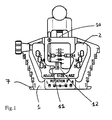
- Figure 1 is a front view of a next meter the invention.
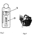
- FIG. 2 is a view of part of the measurer of FIG. 1, namely the probe and its associated graduated support.
- Figure 3 is a perspective view of the meter in Figure 1.
- Figure 4 is a perspective view showing the size installed on the distal end of a femur, the distal cut of which has already been made.
- the measurer consists of a main body 1.
- This main body 1 comprises a base plate 7 intended for be brought into contact with the condyles of the femur (see Figure 4).
- a set 4 probe is mounted movable in vertical translation in FIG. 1 (the vertical direction here being the direction defined by the intersection of the medio-lateral and antero-posterior planes) and comprises, in addition to a probe 8, a plate 5 carrying marks S1, S2, M3, M4, M5, L6, L7, corresponding to the different implant sizes available femoral.
- the main body 1 also comprises a main pointer SZ whose vertical distance (in Figure 3) to the plate 7 is adjusted beforehand, in also taking into account the total height of the plate 5, to indicate the size implant corresponding to a position of the tip 10 of the probe 8.
- the pointer SZ indicates the exact size of the implant that would be required. Note that in general the pointer will not be not exactly opposite an S, M or L mark but between two marks of this kind.
- a slide 2 On the main body, there is also mounted a slide 2, whose sliding relative to the main body is free but can be blocked by an adjustable wrench 3.
- This slide has a first ASZ pointer and a second pointer 11.
- the dimensions of the slide, and in particular the distances measured vertically in Figure 3 between the ASZ pointer and the holes 13, are chosen according to the dimensions of the possible implant sizes (S1, ..., L7) available on the meter, to make sure that the second pointer, when the first pointer moves within the useful range (i.e.
- the second pointer moves opposite a region 6 fixed relative to the main body, in particular on the body main, this region comprising gradations 12, here in millimeters, for indicate the offset from the chosen size, offset corresponding to the resection height to be performed at the posterior level when defining the size implant selected to be perfectly flush with the lower cortex.
- the slide further comprises series of holes 13, here grouped by sizes S, M and L which allows perfect positioning of points that one inserts there to pierce in the bone the precise points of fixing of a guide cut to make the anterior, posterior, anterior chamfer and posterior chamfer, corresponding to the choice of implant size selected by previous use of the meter.
Landscapes
- Health & Medical Sciences (AREA)
- Life Sciences & Earth Sciences (AREA)
- Orthopedic Medicine & Surgery (AREA)
- Transplantation (AREA)
- Surgery (AREA)
- Heart & Thoracic Surgery (AREA)
- Animal Behavior & Ethology (AREA)
- Nuclear Medicine, Radiotherapy & Molecular Imaging (AREA)
- Veterinary Medicine (AREA)
- Oral & Maxillofacial Surgery (AREA)
- Engineering & Computer Science (AREA)
- Biomedical Technology (AREA)
- Public Health (AREA)
- General Health & Medical Sciences (AREA)
- Physical Education & Sports Medicine (AREA)
- Vascular Medicine (AREA)
- Biophysics (AREA)
- Cardiology (AREA)
- Dentistry (AREA)
- Medical Informatics (AREA)
- Molecular Biology (AREA)
- Surgical Instruments (AREA)
- Prostheses (AREA)
- Measurement Of The Respiration, Hearing Ability, Form, And Blood Characteristics Of Living Organisms (AREA)
Abstract
Description
Claims (3)
- Mesureur de taille, comportant un corps (1) principal ayant un palpeur (8) agencé de manière mobile par rapport au corps principal, de sorte qu'un pointeur SZ principal soit déplacé en fonction du réglage en face d'une plage comportant plusieurs repères (S1, S2, M3, M4, M5, L6, L7) correspondant aux tailles d'implant disponibles, caractérisé en ce qu'il comporte un coulisseau monté mobile par rapport au corps principal, le coulisseau comportant un premier pointeur (ASZ) et un deuxième pointeur (11 ), le premier pointeur étant agencé de manière à être déplacé, lors du coulissement du coulisseau (2), en face de ladite plage, et le deuxième coulisseau se déplaçant, lors du mouvement du coulisseau, en face de gradations (12) disposées sur une région (6) fixe par rapport au corps principal, la distance entre les deux pointeurs du coulisseau étant telle que lorsque le premier pointeur est en face d'un des repères correspondant à l'une des tailles d'implant disponibles, le deuxième pointeur indique sur les gradations (12) la hauteur, par exemple en millimètres, de la coupe à réaliser en postérieur afin que l'implant affleure parfaitement au niveau de la corticale antérieure.
- Mesureur suivant la revendication 1, caractérisé en ce que la plage se trouve sur une plaque (5), solidaire du palpeur (8) et sensiblement de forme plane pour s'adapter à un fémur dont la coupe distale a déjà été réalisée.
- Mesureur suivant la revendication 1 ou 2, caractérisé en ce que le corps principal comporte un plateau (7) de réception des condyles, disposé en face du palpeur (8).
Applications Claiming Priority (2)
| Application Number | Priority Date | Filing Date | Title |
|---|---|---|---|
| FR0305061A FR2854062B1 (fr) | 2003-04-24 | 2003-04-24 | Mesureur de taille a utilisation simplifiee |
| FR0305061 | 2003-04-24 |
Publications (2)
| Publication Number | Publication Date |
|---|---|
| EP1470805A1 true EP1470805A1 (fr) | 2004-10-27 |
| EP1470805B1 EP1470805B1 (fr) | 2008-01-23 |
Family
ID=32947375
Family Applications (1)
| Application Number | Title | Priority Date | Filing Date |
|---|---|---|---|
| EP04290750A Expired - Lifetime EP1470805B1 (fr) | 2003-04-24 | 2004-03-19 | Mesureur de taille à utilisation simplifiée |
Country Status (6)
| Country | Link |
|---|---|
| US (1) | US7115133B2 (fr) |
| EP (1) | EP1470805B1 (fr) |
| JP (1) | JP4488408B2 (fr) |
| DE (1) | DE602004011420T2 (fr) |
| ES (1) | ES2297348T3 (fr) |
| FR (1) | FR2854062B1 (fr) |
Cited By (1)
| Publication number | Priority date | Publication date | Assignee | Title |
|---|---|---|---|---|
| US8382764B2 (en) | 2005-07-14 | 2013-02-26 | Depuy International Limited | Femoral sizing guide |
Families Citing this family (21)
| Publication number | Priority date | Publication date | Assignee | Title |
|---|---|---|---|---|
| US20020198529A1 (en) * | 1999-02-16 | 2002-12-26 | Michael A. Masini | Optimizing patellar femoral mechanics through alternative depth referencing |
| US20050187560A1 (en) * | 2004-01-29 | 2005-08-25 | Dietzel Steven E. | Apparatus and method for sizing a distal femur |
| AU2005319025B2 (en) * | 2004-12-21 | 2012-04-19 | Smith & Nephew, Inc. | Rotational alignment femoral sizing guide |
| CA2610672C (fr) * | 2005-06-03 | 2013-09-17 | Depuy Ireland Limited | Instrument destine a s'utiliser dans le remplacement d'une articulation |
| US8585706B2 (en) * | 2005-06-03 | 2013-11-19 | Depuy (Ireland) | Instrument for use in a joint replacement procedure |
| EP1885296B1 (fr) * | 2005-06-03 | 2011-05-18 | LaFosse, Laurent | Instrument destine a etre utilise dans une intervention de remplacement d'articulation |
| GB0803510D0 (en) * | 2008-02-27 | 2008-04-02 | Depuy Orthopaedie Gmbh | Cutting guide |
| GB0813826D0 (en) * | 2008-07-29 | 2008-09-03 | Depuy Ireland Ltd | Apparatus and measuring instrument |
| JP5260252B2 (ja) * | 2008-12-09 | 2013-08-14 | 京セラメディカル株式会社 | 骨寸法測定器 |
| US8828012B2 (en) * | 2009-03-02 | 2014-09-09 | Zimmer, Inc. | Anterior cortex referencing extramedullary femoral cut guide |
| GB0909918D0 (en) | 2009-06-09 | 2009-07-22 | Depuy Ireland | A femoral sizing instrument |
| WO2012125795A2 (fr) * | 2011-03-16 | 2012-09-20 | Smith & Nephew, Inc. | Implant à angle composé |
| CA2854997A1 (fr) * | 2011-11-11 | 2013-05-16 | Depuy (Ireland) | Guide de dimensionnement d'os |
| US10070868B2 (en) | 2013-08-02 | 2018-09-11 | Zimmer, Inc. | Resection shift guide and method |
| US9425832B2 (en) * | 2014-01-16 | 2016-08-23 | Qualcomm Incorporated | Inter carrier-aggregation isolation in a receiver |
| DE102015100049A1 (de) | 2015-01-06 | 2016-07-07 | Waldemar Link Gmbh & Co. Kg | Lehre für die Bestimmung einer für einen Patienten passenden Implantatgröße des Femurimplantats einer Knie-Endoprothese |
| AU2020235885A1 (en) | 2019-03-12 | 2021-09-23 | Depuy Ireland Unlimited Company | Orthopaedic system with insert having a post for medial pivoting of a femoral component |
| CN113710208A (zh) | 2019-03-12 | 2021-11-26 | 德普伊爱尔兰无限公司 | 具有内侧枢转股骨部件和插入物的整形外科系统 |
| US11957591B2 (en) * | 2019-09-10 | 2024-04-16 | Depuy Ireland Unlimited Company | Orthopaedic knee prosthesis system and methods for using same |
| WO2022008755A2 (fr) | 2020-07-10 | 2022-01-13 | Depuy Ireland Unlimited Company | Prothèse de genou orthopédique médiale stabilisée |
| DE102023134668B3 (de) | 2023-12-11 | 2025-03-13 | Aesculap Ag | Implantatschablone und Implantatschablonensystem |
Citations (3)
| Publication number | Priority date | Publication date | Assignee | Title |
|---|---|---|---|---|
| US5417694A (en) * | 1993-11-08 | 1995-05-23 | Smith & Nephew Richards Inc. | Distal femoral cutting guide apparatus with anterior or posterior referencing for use in knee joint replacement surgery |
| JPH08308857A (ja) * | 1995-05-19 | 1996-11-26 | Nakashima Propeller Kk | 大腿骨穴あけガイド |
| US6013081A (en) * | 1998-09-09 | 2000-01-11 | Sulzer Orthopedics Inc. | Apparatus and method for anterior and posterior referenced sizing and distal femur resection |
Family Cites Families (9)
| Publication number | Priority date | Publication date | Assignee | Title |
|---|---|---|---|---|
| US4524766A (en) * | 1982-01-07 | 1985-06-25 | Petersen Thomas D | Surgical knee alignment method and system |
| US4567886A (en) * | 1983-01-06 | 1986-02-04 | Petersen Thomas D | Flexion spacer guide for fitting a knee prosthesis |
| US5141513A (en) * | 1990-05-04 | 1992-08-25 | John Fortune | Surgical template |
| US5445642A (en) * | 1992-09-01 | 1995-08-29 | Depuy Inc. | Method for installing a femoral component |
| US5364401A (en) * | 1992-10-08 | 1994-11-15 | Wright Medical Technology, Inc. | External alignment system for preparing a femur for an implant |
| US5486178A (en) * | 1994-02-16 | 1996-01-23 | Hodge; W. Andrew | Femoral preparation instrumentation system and method |
| US5624444A (en) * | 1995-02-10 | 1997-04-29 | Wixon; Richard | Femoral resection instrumentation including three-dimensional jig and method of use |
| US6024746A (en) * | 1995-05-31 | 2000-02-15 | Lawrence Katz | Method and apparatus for locating bone cuts at the distal condylar femur region to receive a femoral prothesis and to coordinate tibial and patellar resection and replacement with femoral resection and replacement |
| US20040220583A1 (en) * | 2003-02-04 | 2004-11-04 | Zimmer Technology, Inc. | Instrumentation for total knee arthroplasty, and methods of performing same |
-
2003
- 2003-04-24 FR FR0305061A patent/FR2854062B1/fr not_active Expired - Lifetime
-
2004
- 2004-03-19 ES ES04290750T patent/ES2297348T3/es not_active Expired - Lifetime
- 2004-03-19 EP EP04290750A patent/EP1470805B1/fr not_active Expired - Lifetime
- 2004-03-19 DE DE602004011420T patent/DE602004011420T2/de not_active Expired - Lifetime
- 2004-04-06 US US10/818,722 patent/US7115133B2/en not_active Expired - Lifetime
- 2004-04-22 JP JP2004126883A patent/JP4488408B2/ja not_active Expired - Fee Related
Patent Citations (3)
| Publication number | Priority date | Publication date | Assignee | Title |
|---|---|---|---|---|
| US5417694A (en) * | 1993-11-08 | 1995-05-23 | Smith & Nephew Richards Inc. | Distal femoral cutting guide apparatus with anterior or posterior referencing for use in knee joint replacement surgery |
| JPH08308857A (ja) * | 1995-05-19 | 1996-11-26 | Nakashima Propeller Kk | 大腿骨穴あけガイド |
| US6013081A (en) * | 1998-09-09 | 2000-01-11 | Sulzer Orthopedics Inc. | Apparatus and method for anterior and posterior referenced sizing and distal femur resection |
Non-Patent Citations (1)
| Title |
|---|
| PATENT ABSTRACTS OF JAPAN vol. 1997, no. 03 31 March 1997 (1997-03-31) * |
Cited By (1)
| Publication number | Priority date | Publication date | Assignee | Title |
|---|---|---|---|---|
| US8382764B2 (en) | 2005-07-14 | 2013-02-26 | Depuy International Limited | Femoral sizing guide |
Also Published As
| Publication number | Publication date |
|---|---|
| FR2854062B1 (fr) | 2005-06-10 |
| DE602004011420D1 (de) | 2008-03-13 |
| US7115133B2 (en) | 2006-10-03 |
| ES2297348T3 (es) | 2008-05-01 |
| DE602004011420T2 (de) | 2009-01-22 |
| JP2004321802A (ja) | 2004-11-18 |
| US20040215205A1 (en) | 2004-10-28 |
| FR2854062A1 (fr) | 2004-10-29 |
| JP4488408B2 (ja) | 2010-06-23 |
| EP1470805B1 (fr) | 2008-01-23 |
Similar Documents
| Publication | Publication Date | Title |
|---|---|---|
| EP1470805B1 (fr) | Mesureur de taille à utilisation simplifiée | |
| US5658291A (en) | Median ridge referencing patella cutting system | |
| US5176516A (en) | Instrument for measuring a remaining alveolar bone | |
| EP1643916B1 (fr) | Dispositif d'aide pour l'implantation de protheses totales du genou | |
| US8834486B2 (en) | Femoral guide for implanting a femoral knee prosthesis | |
| CN1129402C (zh) | 切割导引器械 | |
| US20200100916A1 (en) | Method of using a measuring instrument in an orthopaedic surgical procedure | |
| US4662075A (en) | Apparatus and method for setting knife blade depth | |
| EP1356775A2 (fr) | Appareil pour la résection de l'ulna | |
| US20030153924A1 (en) | Femoral sizing guide | |
| FR2681778A1 (fr) | Ancillaire modulaire pour la mise en place d'une prothese de genou. | |
| US20030176867A1 (en) | Blade for resection of bone for prosthesis implantation, blade stop and method | |
| US5591174A (en) | Microkeratome and method and apparatus for calibrating a microkeratome | |
| KR19980702249A (ko) | 슬개골 클램프 장치 | |
| JP2021529045A (ja) | 外科用キット及び方法 | |
| FR2737848A1 (fr) | Instrumentation de mise en place d'un implant rotulien prothetique | |
| AU2008200892B2 (en) | Apparatus for indicating the bone thickness between a cavity in a bone and the bone surface | |
| FR2806901A1 (fr) | Materiel de coupe femorale pour la mise en place d'une prothese totale du genou | |
| WO2007021099A1 (fr) | Appareil de mesure de distance pour insertion d’implant dental | |
| EP1961380A1 (fr) | Dispositif de mesure pour moignon fémoral | |
| CN216417354U (zh) | 牙胶尖修剪器 | |
| FR2587196A1 (fr) | Appareil pour reperer in situ les trous transversaux d'une broche creuse implantee dans le canal medullaire, pour la contention des fragments d'un os fracture | |
| FR2829376A1 (fr) | Materiel de reperage de coupes femoro-tibiale | |
| CN222070156U (zh) | 一种股骨头测量取材装置 | |
| JP7390461B1 (ja) | アタッチメントセットおよび骨切削システム |
Legal Events
| Date | Code | Title | Description |
|---|---|---|---|
| PUAI | Public reference made under article 153(3) epc to a published international application that has entered the european phase |
Free format text: ORIGINAL CODE: 0009012 |
|
| AK | Designated contracting states |
Kind code of ref document: A1 Designated state(s): AT BE BG CH CY CZ DE DK EE ES FI FR GB GR HU IE IT LI LU MC NL PL PT RO SE SI SK TR |
|
| AX | Request for extension of the european patent |
Extension state: AL LT LV MK |
|
| 17P | Request for examination filed |
Effective date: 20050407 |
|
| AKX | Designation fees paid |
Designated state(s): CH DE ES FR GB IT LI |
|
| GRAP | Despatch of communication of intention to grant a patent |
Free format text: ORIGINAL CODE: EPIDOSNIGR1 |
|
| RAP1 | Party data changed (applicant data changed or rights of an application transferred) |
Owner name: AESCULAP |
|
| GRAS | Grant fee paid |
Free format text: ORIGINAL CODE: EPIDOSNIGR3 |
|
| GRAA | (expected) grant |
Free format text: ORIGINAL CODE: 0009210 |
|
| AK | Designated contracting states |
Kind code of ref document: B1 Designated state(s): CH DE ES FR GB IT LI |
|
| REG | Reference to a national code |
Ref country code: GB Ref legal event code: FG4D Free format text: NOT ENGLISH |
|
| RIN1 | Information on inventor provided before grant (corrected) |
Inventor name: PLUMET, SYLVIE Inventor name: MOUSSA, SAID |
|
| REG | Reference to a national code |
Ref country code: CH Ref legal event code: EP Ref country code: CH Ref legal event code: NV Representative=s name: E. BLUM & CO. AG PATENT- UND MARKENANWAELTE VSP |
|
| GBT | Gb: translation of ep patent filed (gb section 77(6)(a)/1977) |
Effective date: 20080124 |
|
| REF | Corresponds to: |
Ref document number: 602004011420 Country of ref document: DE Date of ref document: 20080313 Kind code of ref document: P |
|
| REG | Reference to a national code |
Ref country code: ES Ref legal event code: FG2A Ref document number: 2297348 Country of ref document: ES Kind code of ref document: T3 |
|
| PLBE | No opposition filed within time limit |
Free format text: ORIGINAL CODE: 0009261 |
|
| STAA | Information on the status of an ep patent application or granted ep patent |
Free format text: STATUS: NO OPPOSITION FILED WITHIN TIME LIMIT |
|
| 26N | No opposition filed |
Effective date: 20081024 |
|
| REG | Reference to a national code |
Ref country code: FR Ref legal event code: PLFP Year of fee payment: 13 |
|
| REG | Reference to a national code |
Ref country code: FR Ref legal event code: PLFP Year of fee payment: 14 |
|
| REG | Reference to a national code |
Ref country code: FR Ref legal event code: PLFP Year of fee payment: 15 |
|
| PGFP | Annual fee paid to national office [announced via postgrant information from national office to epo] |
Ref country code: GB Payment date: 20220324 Year of fee payment: 19 Ref country code: DE Payment date: 20220322 Year of fee payment: 19 Ref country code: CH Payment date: 20220324 Year of fee payment: 19 |
|
| PGFP | Annual fee paid to national office [announced via postgrant information from national office to epo] |
Ref country code: FR Payment date: 20220322 Year of fee payment: 19 |
|
| PGFP | Annual fee paid to national office [announced via postgrant information from national office to epo] |
Ref country code: IT Payment date: 20220331 Year of fee payment: 19 Ref country code: ES Payment date: 20220420 Year of fee payment: 19 |
|
| REG | Reference to a national code |
Ref country code: DE Ref legal event code: R119 Ref document number: 602004011420 Country of ref document: DE |
|
| REG | Reference to a national code |
Ref country code: CH Ref legal event code: PL |
|
| GBPC | Gb: european patent ceased through non-payment of renewal fee |
Effective date: 20230319 |
|
| PG25 | Lapsed in a contracting state [announced via postgrant information from national office to epo] |
Ref country code: GB Free format text: LAPSE BECAUSE OF NON-PAYMENT OF DUE FEES Effective date: 20230319 |
|
| PG25 | Lapsed in a contracting state [announced via postgrant information from national office to epo] |
Ref country code: LI Free format text: LAPSE BECAUSE OF NON-PAYMENT OF DUE FEES Effective date: 20230331 Ref country code: GB Free format text: LAPSE BECAUSE OF NON-PAYMENT OF DUE FEES Effective date: 20230319 Ref country code: FR Free format text: LAPSE BECAUSE OF NON-PAYMENT OF DUE FEES Effective date: 20230331 Ref country code: DE Free format text: LAPSE BECAUSE OF NON-PAYMENT OF DUE FEES Effective date: 20231003 Ref country code: CH Free format text: LAPSE BECAUSE OF NON-PAYMENT OF DUE FEES Effective date: 20230331 |
|
| PG25 | Lapsed in a contracting state [announced via postgrant information from national office to epo] |
Ref country code: IT Free format text: LAPSE BECAUSE OF NON-PAYMENT OF DUE FEES Effective date: 20230319 |
|
| REG | Reference to a national code |
Ref country code: ES Ref legal event code: FD2A Effective date: 20240430 |
|
| PG25 | Lapsed in a contracting state [announced via postgrant information from national office to epo] |
Ref country code: ES Free format text: LAPSE BECAUSE OF NON-PAYMENT OF DUE FEES Effective date: 20230320 |
|
| PG25 | Lapsed in a contracting state [announced via postgrant information from national office to epo] |
Ref country code: ES Free format text: LAPSE BECAUSE OF NON-PAYMENT OF DUE FEES Effective date: 20230320 |