EP1470773B1 - Verbesserungen eines modularen Möbelsystems - Google Patents
Verbesserungen eines modularen Möbelsystems Download PDFInfo
- Publication number
- EP1470773B1 EP1470773B1 EP04252385A EP04252385A EP1470773B1 EP 1470773 B1 EP1470773 B1 EP 1470773B1 EP 04252385 A EP04252385 A EP 04252385A EP 04252385 A EP04252385 A EP 04252385A EP 1470773 B1 EP1470773 B1 EP 1470773B1
- Authority
- EP
- European Patent Office
- Prior art keywords
- furniture
- end piece
- panel
- members
- furniture system
- Prior art date
- Legal status (The legal status is an assumption and is not a legal conclusion. Google has not performed a legal analysis and makes no representation as to the accuracy of the status listed.)
- Expired - Lifetime
Links
- 238000010276 construction Methods 0.000 description 3
- 239000000463 material Substances 0.000 description 2
- 239000011120 plywood Substances 0.000 description 2
- 230000000717 retained effect Effects 0.000 description 2
- 229910000831 Steel Inorganic materials 0.000 description 1
- 238000003780 insertion Methods 0.000 description 1
- 230000037431 insertion Effects 0.000 description 1
- 230000014759 maintenance of location Effects 0.000 description 1
- 229920002635 polyurethane Polymers 0.000 description 1
- 239000004814 polyurethane Substances 0.000 description 1
- 239000010959 steel Substances 0.000 description 1
Images




Classifications
-
- A—HUMAN NECESSITIES
- A47—FURNITURE; DOMESTIC ARTICLES OR APPLIANCES; COFFEE MILLS; SPICE MILLS; SUCTION CLEANERS IN GENERAL
- A47B—TABLES; DESKS; OFFICE FURNITURE; CABINETS; DRAWERS; GENERAL DETAILS OF FURNITURE
- A47B96/00—Details of cabinets, racks or shelf units not covered by a single one of groups A47B43/00 - A47B95/00; General details of furniture
- A47B96/02—Shelves
-
- A—HUMAN NECESSITIES
- A47—FURNITURE; DOMESTIC ARTICLES OR APPLIANCES; COFFEE MILLS; SPICE MILLS; SUCTION CLEANERS IN GENERAL
- A47B—TABLES; DESKS; OFFICE FURNITURE; CABINETS; DRAWERS; GENERAL DETAILS OF FURNITURE
- A47B47/00—Cabinets, racks or shelf units, characterised by features related to dismountability or building-up from elements
- A47B47/04—Cabinets, racks or shelf units, characterised by features related to dismountability or building-up from elements made mainly of wood or plastics
- A47B47/05—Cabinets, racks or shelf units, characterised by features related to dismountability or building-up from elements made mainly of wood or plastics with panels on a separate frame, e.g. a metal frame
-
- A—HUMAN NECESSITIES
- A47—FURNITURE; DOMESTIC ARTICLES OR APPLIANCES; COFFEE MILLS; SPICE MILLS; SUCTION CLEANERS IN GENERAL
- A47B—TABLES; DESKS; OFFICE FURNITURE; CABINETS; DRAWERS; GENERAL DETAILS OF FURNITURE
- A47B96/00—Details of cabinets, racks or shelf units not covered by a single one of groups A47B43/00 - A47B95/00; General details of furniture
- A47B96/14—Bars, uprights, struts, or like supports, for cabinets, brackets, or the like
- A47B96/1466—Bars, uprights, struts, or like supports, for cabinets, brackets, or the like with longitudinal grooves
- A47B96/1475—Bars, uprights, struts, or like supports, for cabinets, brackets, or the like with longitudinal grooves and perforations
-
- A—HUMAN NECESSITIES
- A47—FURNITURE; DOMESTIC ARTICLES OR APPLIANCES; COFFEE MILLS; SPICE MILLS; SUCTION CLEANERS IN GENERAL
- A47B—TABLES; DESKS; OFFICE FURNITURE; CABINETS; DRAWERS; GENERAL DETAILS OF FURNITURE
- A47B96/00—Details of cabinets, racks or shelf units not covered by a single one of groups A47B43/00 - A47B95/00; General details of furniture
- A47B96/20—Furniture panels or like furniture elements
- A47B96/201—Edge features
Definitions
- the present invention relates to an improved furniture system.
- the furniture system may be used to produce items of furniture for use in an office environment or the like.
- Such furniture systems are required to permit of readily assembly and disassembly, while being of sturdy and robust construction when assembled during use.
- DE 2 99 17 483U discloses a shelving unit comprising a plurality of panel members arranged to be secure together vertically or horizontally in which the ends of one panel member are adapted to be secured in an end piece.
- US 3 513 606 A discloses a joint structure for enabling the construction of a structural framework in various combinations within panels, including curved panels, to create, for example, furniture or display racks.
- a modular furniture system comprises a plurality of panel members, at least one panel member having a curvature, a plurality of end pieces adapted to be located between and secured to adjacent panel members, the end pieces and the at least one panel member forming a curved framework, the ends of each panel member being provided with a recessed channel within which one of the end pieces is received, and the or each end piece has at least one outwardly extending flange formed as a lug extending from the or each end piece characterised in that the channel comprises a first part and a second part, the first part adapted to receive a thickness of the end piece and a second part adapted to receive the at least one flange of the end piece, the end piece being hollow and of generally rectangular section.
- a plurality of through bores extend from a one side of the panel member through to the second part of the channel.
- each end piece is formed with a plurality of slots.
- the furniture system preferably further comprises one or more fixing members to be fitted into the one or more of the plurality of slots and a furniture component securable to the one or more fixing members.
- the furniture component comprises one of the following:
- each curved panel has a curvature
- the curvature of each curved panel is the same.
- FIG. 1 there may be seen a furniture arrangement formed in accordance with a first embodiment of the present invention comprising adjacent first and second panel members 2,4 secured to an end piece 6.
- Each of the first and second panel members 2,4 can be seen to possess a curvature.
- a furniture component 8 is secured to the end piece 6 by a fixing member 10.
- the end piece 6 is provided with first and second outwardly extending flange members 12.
- Each of the first and second panel members 2,4 is secured to a respective outwardly extending flange member 12 by secondary fixings 14.
- each of the panel members 2,4 may be formed from any suitable material.
- each panel member 2,4 comprises one or more sheets of laminated plywood 28.
- each panel member has a span of a metre.
- the laminated plywood 28 may additionally be provided with a surface covering 30.
- Each panel member 2,4 and associated end piece 6 is of a suitable height for the furniture arrangement to be constructed. In addition to the inherent strength of the material forming the panel member, the curvature increases the strength of the panel member and the furniture arrangement produced using such a panel member.
- Each end of the respective first and second panel members 2,4 is provided with a channel 16.
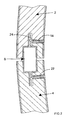
- the channel 16 comprises a first part 18 and a second part 20, the first part 18 adapted to receive a thickness of the end piece 6 and the second part 20 adapted to receive the at least one flange member 12 of the end piece 6.
- the channel 16 is formed as a routed rebated slot.
- Openings 22 are provided in one side of each panel member between an outer face of the respective panel member 2,4 and the second part 20 of the recess 16.
- the secondary fixings 14, such as lug or grub screws, extend through and are retained within the openings 22 to secure the respective panel member 2,4 to the end piece 6.
- the secondary fixings 14 may then be used to secure a furniture component 8 to create a furniture arrangement formed in accordance with the present invention.
- the openings 22 may be provided with a taper or beveled edge to aid the introduction of the secondary fixings 14 into the openings 22.
- each panel member 2,4 is first generally arranged in position in relation to the end piece 6. It will not always be possible precisely to align the panel member 2,4 to the end piece 6. However, the presence of a tapered recess 24 on a first surface of the flange member 12 ensures that when the secondary fixing 14 is tightened to the flange member 12 the panel member 2,4 is drawn into position against the end piece 6. When the respective panel members 2,4 are drawn into position only a shadow line between the respective panel members 2,4 is visible to a user of the furniture arrangement.
- the panel member at each end of a furniture arrangement may have a channel 16 only at one end.
- the other end of such a panel member will have a suitable finish, such as a rounded edge.
- the construction of a suitable end piece 6 is shown more clearly in Figure 3.
- the end piece 6 is hollow and of generally rectangular section.
- the flange member 12 may take the form of a plurality of lugs 32 (in the embodiment illustrated two) rather than a single flange 12 to each side of the end piece 6.
- Normally disposed between the flange members 12 are a plurality of vertical slots 34 extending through a thickness of the end piece 6.
- the slots 34 are spaced at predetermined intervals on both a front and rear surface of each end piece 6.
- the end piece 6 is formed from a hollow steel section to which the plurality of lugs 32 have been welded.
- FIG. 3a shows a furniture component 8 in the form of a side shelf member 40 having two fixing members 10 extending from a rear surface.
- the fixing members 10 are arranged on the side shelf member 40 at suitable intervals to fit into corresponding vertical slots 34.
- the side shelf member 40 has a plurality of parallel fixing points 41 to which the ends of a suitable member may be fixed to provide a shelf.
- a suitable fixing member 10 is shown in Figure 4.
- the fixing member 10 comprises a front portion 36 and a rear portion 38.
- the front portion 36 comprises a plate having a depending hook 37 for insertion and retention within a suitable end piece slot 34.
- the rear portion 38 comprises a locking portion for securing to a furniture component 8.
- the locking portion comprises a serrated tongue for driving into a furniture component 8 to engage therein.
- the fixing member 10 may be provided to a user as an integral part of the furniture component 8 (as in the case of the side shelf member 40 described above) or be formed separately for subsequent attachment to a furniture component 8 when inserted and retained within an end piece slot 34.
- Blade fixings 42 are used to provide additional support for furniture components 8 such as desk tops 44 and the like.
- the blade fixing 42 is secured by one or more fixing members 10 to an end piece 6 between adjacent first and second panel members 2,4.
- a through bore may conveniently be formed by an internally threaded bushing 50 extending through both the blade fixing 42 and the fixing member 10, or alternatively solely through the blade fixing 42.
- a first end of respective first and second brackets 51,52 may then be bolted to each side of the blade fixing 42.
- Each of the first and second brackets 51,52 is substantially L-shaped, an end in use remote from the blade fixing 42 being conveniently secured to an adjacent panel member 2,4.
- the end of the bracket 51,52 adjacent the blade fixing 42 may be adapted to hang over a shaft of a bolt 53,54 extending into the threaded bore.
- Figure 6 shows a desktop 44 to blade fixing 42 detail in which it can be seen that following attachment of the blade fixing 42 to an end piece 6 at each end of a panel member 2, 4 of the furniture system the desktop 44 need only be lowered into position and then fixed to the blade fixing 42 at suitable fixing points 41. In use, the desktop 44 bears onto the blade fixing 42.
- the blade fixing 42 may additionally be provided with an aperture 56 to serve as a cable guide. Additionally, or alternatively, recesses may be formed in the edge of a desktop 44 to serve as a cable guide.
- the forward facing edges of the furniture components 8 are conveniently provided with a finish such as a moulded polyurethane edge trim to protect against wear.
- the blade fixing 42 may also be provided with additional fixing points 41 to which may be secured furniture components 8 in the form of shelf units.
- additional fixing points 41 to which may be secured furniture components 8 in the form of shelf units.
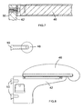
- attachment of a furniture component such as a shelf unit 46 to a blade fixing 42 is shown.
- the blade fixing is provided with a through bore that is conveniently formed by an internally threaded bushing 50.
- a first end of a shelf unit 46 may then be bolted to the blade fixing 42 as shown in Figure 7.
- FIG 8 a blade fixing 42 can be seen, together with the fixing members 10 extending rearwardly therefrom.
- a seat 46 is shown in position on the blade fixing 42.
- a seat back 48 Above the seat 46 can seen a seat back 48, again having a fixing member 10 extending from the rear thereof.
- Figure 9 shows a first arrangement of furniture produced in accordance with the present furniture system.
- a relatively high set of panel members have been used to provide a low bookcase 60 to one side of the panel members and a shelf unit with table top 62 and upper shelf unit 64 to the other.
- a relatively low set of panel members have been used to construct a seating unit 66 with a back rest 48 to one side of the panel members and a desk unit 68 to the other.
- Figure 10 shows a second arrangement of furniture produced in accordance with the present furniture system.
- a set of panel members of intermediate height have been used to construct a seating unit 66 to one side of the panel members and a desk unit 68 to the other.
- a relatively high set of panel members have been used to provide a tall bookcase 70 to one side of the panel members and a seating unit 66 with a back rest 48 to the other.
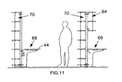
- Figure 11 shows a third arrangement of furniture produced in accordance with the present furniture system.
- a relatively high set of panel members have been used to provide a tall bookcase 70 to one side of the panel members and a desk unit 68 to the other.
- a relatively high set of panel members have been used to construct a tall bookcase 70 to one side of the panel members and a desk unit 68 and upper shelf unit to the other.
- the desktop 44 does not extend to the panel member but is spaced in relation thereto. The space may be used to pass cables through to computers or the like in use located on the desktop 44.
- Figures 9, 10 and 11 illustrate the versatility of the modular furniture system provided for by the invention. It will be understood that the furniture system may also use panel members without a curvature in constructing a furniture module, but that in order to provide appropriate strength and rigidity at least one, and preferably more, panel members having a curvature should be used.
- furniture components including but not limited to, lighting units.
Landscapes
- Life Sciences & Earth Sciences (AREA)
- Engineering & Computer Science (AREA)
- Wood Science & Technology (AREA)
- Furniture Connections (AREA)
- Assembled Shelves (AREA)
- Tables And Desks Characterized By Structural Shape (AREA)
- Coin-Freed Apparatuses For Hiring Articles (AREA)
- Financial Or Insurance-Related Operations Such As Payment And Settlement (AREA)
- Cabinets, Racks, Or The Like Of Rigid Construction (AREA)
Claims (6)
- Modulares Möbelsystem, das mehrere Tafelelemente (2, 4), wobei wenigstens ein Tafelelement (2, 4) eine Krümmung hat, und mehrere Endstücke (6), dafür eingerichtet, zwischen benachbarten Tafelelementen (2, 4) angeordnet und an denselben befestigt zu werden, umfasst, wobei die Endstücke (6) und das wenigstens eine Tafelelement (2, 4) ein gekrümmtes Tragwerk bilden, wobei die Enden jedes Tafelelements (2, 4) mit einem ausgesparten Kanal (16) versehen sind, innerhalb dessen eines der Endstücke (6) aufgenommen wird, und wobei das oder jedes Endstück (6) wenigstens einen sich nach außen erstreckenden Flanschabschnitt (12) hat, der als ein Ansatz geformt ist, der sich von dem oder jedem Endstück (6) aus erstreckt, dadurch gekennzeichnet, dass der Kanal (16) einen ersten Teil (18) und einen zweiten Teil (20) umfasst, wobei der erste Teil (18) dafür eingerichtet ist, eine Dicke des Endstücks (6) aufzunehmen, und ein zweiter Teil (20) dafür eingerichtet ist, den Flanschabschnitt (12) des Endstücks (6) aufzunehmen, wobei das Endstück (6) hohl und von allgemein rechteckigem Querschnitt ist.
- Möbelsystem nach Anspruch 1, dadurch gekennzeichnet, dass sich mehrere Durchgangsbohrungen (22) von einer Seite des Tafelelements (2, 4) aus hindurch zum zweiten Teil (20) des ausgesparten Kanals (16) erstrecken.
- Möbelsystem nach Anspruch 1 oder Anspruch 2, dadurch gekennzeichnet, dass jedes Endstück (6) mit mehreren Schlitzen (34) geformt ist.
- Möbelsystem nach Anspruch 3, dadurch gekennzeichnet, dass das System ferner ein oder mehrere Befestigungselemente (10), die in den einen oder mehrere der mehreren Schlitze (34) gepasst werden kann, und ein Möbelbauteil, das an dem einen oder mehreren Befestigungselementen (10) befestigt werden kann, umfasst.
- Möbelsystem nach Anspruch 4, dadurch gekennzeichnet, dass das Möbelbauteil eine der folgenden Komponenten umfasst:eine Fachbodeneinheit (60, 64, 70),ein Seitenfachbodenelement,eine Schreibtischplatte (44, 68),einen Sitz (46, 66) odereine Sitzlehne (48).
- Möbelsystem nach einem der Ansprüche 1 bis 4, dadurch gekennzeichnet, dass, wenn mehr als eine Tafel (2, 4) eine Krümmung hat, die Krümmung jeder gekrümmten Tafel (2, 4) die gleiche ist.
Applications Claiming Priority (2)
| Application Number | Priority Date | Filing Date | Title |
|---|---|---|---|
| GB0309543 | 2003-04-26 | ||
| GB0309543 | 2003-04-26 |
Publications (2)
| Publication Number | Publication Date |
|---|---|
| EP1470773A1 EP1470773A1 (de) | 2004-10-27 |
| EP1470773B1 true EP1470773B1 (de) | 2007-01-24 |
Family
ID=32947468
Family Applications (1)
| Application Number | Title | Priority Date | Filing Date |
|---|---|---|---|
| EP04252385A Expired - Lifetime EP1470773B1 (de) | 2003-04-26 | 2004-04-23 | Verbesserungen eines modularen Möbelsystems |
Country Status (3)
| Country | Link |
|---|---|
| EP (1) | EP1470773B1 (de) |
| AT (1) | ATE352230T1 (de) |
| DE (1) | DE602004004434T2 (de) |
Family Cites Families (4)
| Publication number | Priority date | Publication date | Assignee | Title |
|---|---|---|---|---|
| GB792979A (en) * | 1955-04-27 | 1958-04-09 | L A Darling Company | Improvements relating to paneled wall or partition structures provided with supports for shelf and like brackets |
| US3513606A (en) * | 1968-02-21 | 1970-05-26 | Vernon H Jones | Structural framework and connector joint therefor |
| DE8811762U1 (de) * | 1988-09-16 | 1988-11-10 | Fahrenberger Apothekenbau Gmbh, 5309 Meckenheim | Möbelelement mit Stützsäule für Ladeneinrichtungen, insbesondere für Apothekeneinrichtungen |
| DE29917483U1 (de) * | 1999-10-04 | 2000-02-17 | Eba Paneelwerk GmbH, 48691 Vreden | Leicht handhabbare Vorrichtung zum formschlüssigen Verbinden von Feder und Trägerteil |
-
2004
- 2004-04-23 AT AT04252385T patent/ATE352230T1/de not_active IP Right Cessation
- 2004-04-23 DE DE602004004434T patent/DE602004004434T2/de not_active Expired - Lifetime
- 2004-04-23 EP EP04252385A patent/EP1470773B1/de not_active Expired - Lifetime
Also Published As
| Publication number | Publication date |
|---|---|
| DE602004004434D1 (de) | 2007-03-15 |
| ATE352230T1 (de) | 2007-02-15 |
| EP1470773A1 (de) | 2004-10-27 |
| DE602004004434T2 (de) | 2007-11-29 |
Similar Documents
| Publication | Publication Date | Title |
|---|---|---|
| USRE38836E1 (en) | Cabinet system | |
| US8033059B2 (en) | Paneling system | |
| US5921044A (en) | Display wall assembly and method of making same | |
| US11006749B2 (en) | Systems, brackets, and methods for mounting storage structures to office work surfaces | |
| US20120304441A1 (en) | Table and privacy screen assembly | |
| US8037642B2 (en) | Panel assembly including slat wall segment | |
| US6447080B1 (en) | Freestanding furniture defining office with adjustable footprint | |
| CA2173568A1 (en) | Cabinet construction system | |
| WO1990003749A1 (en) | Horizontally oriented demountable partition system | |
| US5346296A (en) | Assembly of wall units with concealed wire storage | |
| WO2002094063A2 (en) | Support structure and method of assembly thereof | |
| EP3343114B1 (de) | Oberflächenmontierte küchenkochfeldeinheit und vorrichtung zur installation davon | |
| US20120167500A1 (en) | Upmount overhead brackets for office partition systems | |
| US20020195029A1 (en) | Adjustable sliding-shelf assemblies and method of adjusting the same | |
| WO2012063089A1 (en) | Temporary walling panels | |
| US5988576A (en) | Binder bin mounting bracket | |
| US20070204771A1 (en) | Height adjustable leg assembly | |
| EP1470773A1 (de) | Verbesserungen eines modularen Möbelsystems | |
| US20070278168A1 (en) | Decorative wall hanging assembly | |
| US20080067906A1 (en) | Modular components for building structures | |
| US20070215765A1 (en) | Height adjustable support assembly for supporting a furniture component above a work surface | |
| US4589350A (en) | Shelf assembly | |
| US3829187A (en) | Counter fixture | |
| US10687621B2 (en) | Spacer assembly | |
| GB2144974A (en) | A support bracket for a wall mounted rack system |
Legal Events
| Date | Code | Title | Description |
|---|---|---|---|
| PUAI | Public reference made under article 153(3) epc to a published international application that has entered the european phase |
Free format text: ORIGINAL CODE: 0009012 |
|
| AK | Designated contracting states |
Kind code of ref document: A1 Designated state(s): AT BE BG CH CY CZ DE DK EE ES FI FR GB GR HU IE IT LI LU MC NL PL PT RO SE SI SK TR |
|
| AX | Request for extension of the european patent |
Extension state: AL HR LT LV MK |
|
| 17P | Request for examination filed |
Effective date: 20050422 |
|
| 17Q | First examination report despatched |
Effective date: 20050527 |
|
| AKX | Designation fees paid |
Designated state(s): AT BE BG CH CY CZ DE DK EE ES FI FR GB GR HU IE IT LI LU MC NL PL PT RO SE SI SK TR |
|
| GRAP | Despatch of communication of intention to grant a patent |
Free format text: ORIGINAL CODE: EPIDOSNIGR1 |
|
| GRAS | Grant fee paid |
Free format text: ORIGINAL CODE: EPIDOSNIGR3 |
|
| GRAA | (expected) grant |
Free format text: ORIGINAL CODE: 0009210 |
|
| AK | Designated contracting states |
Kind code of ref document: B1 Designated state(s): AT BE BG CH CY CZ DE DK EE ES FI FR GB GR HU IE IT LI LU MC NL PL PT RO SE SI SK TR |
|
| PG25 | Lapsed in a contracting state [announced via postgrant information from national office to epo] |
Ref country code: SI Free format text: LAPSE BECAUSE OF FAILURE TO SUBMIT A TRANSLATION OF THE DESCRIPTION OR TO PAY THE FEE WITHIN THE PRESCRIBED TIME-LIMIT Effective date: 20070124 Ref country code: AT Free format text: LAPSE BECAUSE OF FAILURE TO SUBMIT A TRANSLATION OF THE DESCRIPTION OR TO PAY THE FEE WITHIN THE PRESCRIBED TIME-LIMIT Effective date: 20070124 Ref country code: PL Free format text: LAPSE BECAUSE OF FAILURE TO SUBMIT A TRANSLATION OF THE DESCRIPTION OR TO PAY THE FEE WITHIN THE PRESCRIBED TIME-LIMIT Effective date: 20070124 Ref country code: FI Free format text: LAPSE BECAUSE OF FAILURE TO SUBMIT A TRANSLATION OF THE DESCRIPTION OR TO PAY THE FEE WITHIN THE PRESCRIBED TIME-LIMIT Effective date: 20070124 Ref country code: NL Free format text: LAPSE BECAUSE OF FAILURE TO SUBMIT A TRANSLATION OF THE DESCRIPTION OR TO PAY THE FEE WITHIN THE PRESCRIBED TIME-LIMIT Effective date: 20070124 Ref country code: LI Free format text: LAPSE BECAUSE OF FAILURE TO SUBMIT A TRANSLATION OF THE DESCRIPTION OR TO PAY THE FEE WITHIN THE PRESCRIBED TIME-LIMIT Effective date: 20070124 Ref country code: CH Free format text: LAPSE BECAUSE OF FAILURE TO SUBMIT A TRANSLATION OF THE DESCRIPTION OR TO PAY THE FEE WITHIN THE PRESCRIBED TIME-LIMIT Effective date: 20070124 Ref country code: DK Free format text: LAPSE BECAUSE OF FAILURE TO SUBMIT A TRANSLATION OF THE DESCRIPTION OR TO PAY THE FEE WITHIN THE PRESCRIBED TIME-LIMIT Effective date: 20070124 |
|
| REG | Reference to a national code |
Ref country code: GB Ref legal event code: FG4D |
|
| REG | Reference to a national code |
Ref country code: CH Ref legal event code: EP |
|
| REG | Reference to a national code |
Ref country code: IE Ref legal event code: FG4D |
|
| REF | Corresponds to: |
Ref document number: 602004004434 Country of ref document: DE Date of ref document: 20070315 Kind code of ref document: P |
|
| PG25 | Lapsed in a contracting state [announced via postgrant information from national office to epo] |
Ref country code: SE Free format text: LAPSE BECAUSE OF FAILURE TO SUBMIT A TRANSLATION OF THE DESCRIPTION OR TO PAY THE FEE WITHIN THE PRESCRIBED TIME-LIMIT Effective date: 20070424 |
|
| PG25 | Lapsed in a contracting state [announced via postgrant information from national office to epo] |
Ref country code: BG Free format text: LAPSE BECAUSE OF FAILURE TO SUBMIT A TRANSLATION OF THE DESCRIPTION OR TO PAY THE FEE WITHIN THE PRESCRIBED TIME-LIMIT Effective date: 20070425 |
|
| PG25 | Lapsed in a contracting state [announced via postgrant information from national office to epo] |
Ref country code: ES Free format text: LAPSE BECAUSE OF FAILURE TO SUBMIT A TRANSLATION OF THE DESCRIPTION OR TO PAY THE FEE WITHIN THE PRESCRIBED TIME-LIMIT Effective date: 20070505 |
|
| PG25 | Lapsed in a contracting state [announced via postgrant information from national office to epo] |
Ref country code: PT Free format text: LAPSE BECAUSE OF FAILURE TO SUBMIT A TRANSLATION OF THE DESCRIPTION OR TO PAY THE FEE WITHIN THE PRESCRIBED TIME-LIMIT Effective date: 20070625 |
|
| ET | Fr: translation filed | ||
| REG | Reference to a national code |
Ref country code: CH Ref legal event code: PL |
|
| NLV1 | Nl: lapsed or annulled due to failure to fulfill the requirements of art. 29p and 29m of the patents act | ||
| PG25 | Lapsed in a contracting state [announced via postgrant information from national office to epo] |
Ref country code: SK Free format text: LAPSE BECAUSE OF FAILURE TO SUBMIT A TRANSLATION OF THE DESCRIPTION OR TO PAY THE FEE WITHIN THE PRESCRIBED TIME-LIMIT Effective date: 20070124 |
|
| PLBE | No opposition filed within time limit |
Free format text: ORIGINAL CODE: 0009261 |
|
| STAA | Information on the status of an ep patent application or granted ep patent |
Free format text: STATUS: NO OPPOSITION FILED WITHIN TIME LIMIT |
|
| 26N | No opposition filed |
Effective date: 20071025 |
|
| PG25 | Lapsed in a contracting state [announced via postgrant information from national office to epo] |
Ref country code: RO Free format text: LAPSE BECAUSE OF FAILURE TO SUBMIT A TRANSLATION OF THE DESCRIPTION OR TO PAY THE FEE WITHIN THE PRESCRIBED TIME-LIMIT Effective date: 20070124 Ref country code: BE Free format text: LAPSE BECAUSE OF FAILURE TO SUBMIT A TRANSLATION OF THE DESCRIPTION OR TO PAY THE FEE WITHIN THE PRESCRIBED TIME-LIMIT Effective date: 20070124 Ref country code: CZ Free format text: LAPSE BECAUSE OF FAILURE TO SUBMIT A TRANSLATION OF THE DESCRIPTION OR TO PAY THE FEE WITHIN THE PRESCRIBED TIME-LIMIT Effective date: 20070124 |
|
| PG25 | Lapsed in a contracting state [announced via postgrant information from national office to epo] |
Ref country code: GR Free format text: LAPSE BECAUSE OF FAILURE TO SUBMIT A TRANSLATION OF THE DESCRIPTION OR TO PAY THE FEE WITHIN THE PRESCRIBED TIME-LIMIT Effective date: 20070425 |
|
| PG25 | Lapsed in a contracting state [announced via postgrant information from national office to epo] |
Ref country code: IE Free format text: LAPSE BECAUSE OF NON-PAYMENT OF DUE FEES Effective date: 20070423 |
|
| PG25 | Lapsed in a contracting state [announced via postgrant information from national office to epo] |
Ref country code: EE Free format text: LAPSE BECAUSE OF FAILURE TO SUBMIT A TRANSLATION OF THE DESCRIPTION OR TO PAY THE FEE WITHIN THE PRESCRIBED TIME-LIMIT Effective date: 20070124 |
|
| PG25 | Lapsed in a contracting state [announced via postgrant information from national office to epo] |
Ref country code: MC Free format text: LAPSE BECAUSE OF NON-PAYMENT OF DUE FEES Effective date: 20070430 |
|
| PG25 | Lapsed in a contracting state [announced via postgrant information from national office to epo] |
Ref country code: CY Free format text: LAPSE BECAUSE OF FAILURE TO SUBMIT A TRANSLATION OF THE DESCRIPTION OR TO PAY THE FEE WITHIN THE PRESCRIBED TIME-LIMIT Effective date: 20070124 |
|
| PG25 | Lapsed in a contracting state [announced via postgrant information from national office to epo] |
Ref country code: LU Free format text: LAPSE BECAUSE OF NON-PAYMENT OF DUE FEES Effective date: 20070423 |
|
| PG25 | Lapsed in a contracting state [announced via postgrant information from national office to epo] |
Ref country code: TR Free format text: LAPSE BECAUSE OF FAILURE TO SUBMIT A TRANSLATION OF THE DESCRIPTION OR TO PAY THE FEE WITHIN THE PRESCRIBED TIME-LIMIT Effective date: 20070124 Ref country code: HU Free format text: LAPSE BECAUSE OF FAILURE TO SUBMIT A TRANSLATION OF THE DESCRIPTION OR TO PAY THE FEE WITHIN THE PRESCRIBED TIME-LIMIT Effective date: 20070725 |
|
| PGFP | Annual fee paid to national office [announced via postgrant information from national office to epo] |
Ref country code: DE Payment date: 20120425 Year of fee payment: 9 |
|
| PGFP | Annual fee paid to national office [announced via postgrant information from national office to epo] |
Ref country code: FR Payment date: 20120504 Year of fee payment: 9 |
|
| PGFP | Annual fee paid to national office [announced via postgrant information from national office to epo] |
Ref country code: IT Payment date: 20120420 Year of fee payment: 9 |
|
| PG25 | Lapsed in a contracting state [announced via postgrant information from national office to epo] |
Ref country code: DE Free format text: LAPSE BECAUSE OF NON-PAYMENT OF DUE FEES Effective date: 20131101 |
|
| REG | Reference to a national code |
Ref country code: FR Ref legal event code: ST Effective date: 20131231 |
|
| REG | Reference to a national code |
Ref country code: DE Ref legal event code: R119 Ref document number: 602004004434 Country of ref document: DE Effective date: 20131101 |
|
| PG25 | Lapsed in a contracting state [announced via postgrant information from national office to epo] |
Ref country code: IT Free format text: LAPSE BECAUSE OF NON-PAYMENT OF DUE FEES Effective date: 20130423 Ref country code: FR Free format text: LAPSE BECAUSE OF NON-PAYMENT OF DUE FEES Effective date: 20130430 |
|
| PGFP | Annual fee paid to national office [announced via postgrant information from national office to epo] |
Ref country code: GB Payment date: 20220303 Year of fee payment: 19 |
|
| GBPC | Gb: european patent ceased through non-payment of renewal fee |
Effective date: 20230423 |
|
| PG25 | Lapsed in a contracting state [announced via postgrant information from national office to epo] |
Ref country code: GB Free format text: LAPSE BECAUSE OF NON-PAYMENT OF DUE FEES Effective date: 20230423 |
|
| PG25 | Lapsed in a contracting state [announced via postgrant information from national office to epo] |
Ref country code: GB Free format text: LAPSE BECAUSE OF NON-PAYMENT OF DUE FEES Effective date: 20230423 |