EP1470623B1 - Systeme laser a femtosecondes pour le traitement precis de matiere et de tissus - Google Patents
Systeme laser a femtosecondes pour le traitement precis de matiere et de tissus Download PDFInfo
- Publication number
- EP1470623B1 EP1470623B1 EP03704425A EP03704425A EP1470623B1 EP 1470623 B1 EP1470623 B1 EP 1470623B1 EP 03704425 A EP03704425 A EP 03704425A EP 03704425 A EP03704425 A EP 03704425A EP 1470623 B1 EP1470623 B1 EP 1470623B1
- Authority
- EP
- European Patent Office
- Prior art keywords
- laser
- focus
- deflection
- repetition rate
- oscillator
- Prior art date
- Legal status (The legal status is an assumption and is not a legal conclusion. Google has not performed a legal analysis and makes no representation as to the accuracy of the status listed.)
- Expired - Lifetime
Links
Images
Classifications
-
- B—PERFORMING OPERATIONS; TRANSPORTING
- B23—MACHINE TOOLS; METAL-WORKING NOT OTHERWISE PROVIDED FOR
- B23K—SOLDERING OR UNSOLDERING; WELDING; CLADDING OR PLATING BY SOLDERING OR WELDING; CUTTING BY APPLYING HEAT LOCALLY, e.g. FLAME CUTTING; WORKING BY LASER BEAM
- B23K26/00—Working by laser beam, e.g. welding, cutting or boring
- B23K26/08—Devices involving relative movement between laser beam and workpiece
-
- A—HUMAN NECESSITIES
- A61—MEDICAL OR VETERINARY SCIENCE; HYGIENE
- A61F—FILTERS IMPLANTABLE INTO BLOOD VESSELS; PROSTHESES; DEVICES PROVIDING PATENCY TO, OR PREVENTING COLLAPSING OF, TUBULAR STRUCTURES OF THE BODY, e.g. STENTS; ORTHOPAEDIC, NURSING OR CONTRACEPTIVE DEVICES; FOMENTATION; TREATMENT OR PROTECTION OF EYES OR EARS; BANDAGES, DRESSINGS OR ABSORBENT PADS; FIRST-AID KITS
- A61F9/00—Methods or devices for treatment of the eyes; Devices for putting-in contact lenses; Devices to correct squinting; Apparatus to guide the blind; Protective devices for the eyes, carried on the body or in the hand
- A61F9/007—Methods or devices for eye surgery
- A61F9/008—Methods or devices for eye surgery using laser
- A61F9/00825—Methods or devices for eye surgery using laser for photodisruption
- A61F9/00827—Refractive correction, e.g. lenticle
-
- A—HUMAN NECESSITIES
- A61—MEDICAL OR VETERINARY SCIENCE; HYGIENE
- A61F—FILTERS IMPLANTABLE INTO BLOOD VESSELS; PROSTHESES; DEVICES PROVIDING PATENCY TO, OR PREVENTING COLLAPSING OF, TUBULAR STRUCTURES OF THE BODY, e.g. STENTS; ORTHOPAEDIC, NURSING OR CONTRACEPTIVE DEVICES; FOMENTATION; TREATMENT OR PROTECTION OF EYES OR EARS; BANDAGES, DRESSINGS OR ABSORBENT PADS; FIRST-AID KITS
- A61F9/00—Methods or devices for treatment of the eyes; Devices for putting-in contact lenses; Devices to correct squinting; Apparatus to guide the blind; Protective devices for the eyes, carried on the body or in the hand
- A61F9/007—Methods or devices for eye surgery
- A61F9/008—Methods or devices for eye surgery using laser
- A61F9/00825—Methods or devices for eye surgery using laser for photodisruption
- A61F9/00831—Transplantation
-
- A—HUMAN NECESSITIES
- A61—MEDICAL OR VETERINARY SCIENCE; HYGIENE
- A61F—FILTERS IMPLANTABLE INTO BLOOD VESSELS; PROSTHESES; DEVICES PROVIDING PATENCY TO, OR PREVENTING COLLAPSING OF, TUBULAR STRUCTURES OF THE BODY, e.g. STENTS; ORTHOPAEDIC, NURSING OR CONTRACEPTIVE DEVICES; FOMENTATION; TREATMENT OR PROTECTION OF EYES OR EARS; BANDAGES, DRESSINGS OR ABSORBENT PADS; FIRST-AID KITS
- A61F9/00—Methods or devices for treatment of the eyes; Devices for putting-in contact lenses; Devices to correct squinting; Apparatus to guide the blind; Protective devices for the eyes, carried on the body or in the hand
- A61F9/007—Methods or devices for eye surgery
- A61F9/008—Methods or devices for eye surgery using laser
- A61F9/00825—Methods or devices for eye surgery using laser for photodisruption
- A61F9/00836—Flap cutting
-
- A—HUMAN NECESSITIES
- A61—MEDICAL OR VETERINARY SCIENCE; HYGIENE
- A61F—FILTERS IMPLANTABLE INTO BLOOD VESSELS; PROSTHESES; DEVICES PROVIDING PATENCY TO, OR PREVENTING COLLAPSING OF, TUBULAR STRUCTURES OF THE BODY, e.g. STENTS; ORTHOPAEDIC, NURSING OR CONTRACEPTIVE DEVICES; FOMENTATION; TREATMENT OR PROTECTION OF EYES OR EARS; BANDAGES, DRESSINGS OR ABSORBENT PADS; FIRST-AID KITS
- A61F9/00—Methods or devices for treatment of the eyes; Devices for putting-in contact lenses; Devices to correct squinting; Apparatus to guide the blind; Protective devices for the eyes, carried on the body or in the hand
- A61F9/007—Methods or devices for eye surgery
- A61F9/008—Methods or devices for eye surgery using laser
- A61F9/00825—Methods or devices for eye surgery using laser for photodisruption
- A61F9/0084—Laser features or special beam parameters therefor
-
- A—HUMAN NECESSITIES
- A61—MEDICAL OR VETERINARY SCIENCE; HYGIENE
- A61F—FILTERS IMPLANTABLE INTO BLOOD VESSELS; PROSTHESES; DEVICES PROVIDING PATENCY TO, OR PREVENTING COLLAPSING OF, TUBULAR STRUCTURES OF THE BODY, e.g. STENTS; ORTHOPAEDIC, NURSING OR CONTRACEPTIVE DEVICES; FOMENTATION; TREATMENT OR PROTECTION OF EYES OR EARS; BANDAGES, DRESSINGS OR ABSORBENT PADS; FIRST-AID KITS
- A61F9/00—Methods or devices for treatment of the eyes; Devices for putting-in contact lenses; Devices to correct squinting; Apparatus to guide the blind; Protective devices for the eyes, carried on the body or in the hand
- A61F9/007—Methods or devices for eye surgery
- A61F9/008—Methods or devices for eye surgery using laser
- A61F9/009—Auxiliary devices making contact with the eyeball and coupling in laser light, e.g. goniolenses
-
- B—PERFORMING OPERATIONS; TRANSPORTING
- B23—MACHINE TOOLS; METAL-WORKING NOT OTHERWISE PROVIDED FOR
- B23K—SOLDERING OR UNSOLDERING; WELDING; CLADDING OR PLATING BY SOLDERING OR WELDING; CUTTING BY APPLYING HEAT LOCALLY, e.g. FLAME CUTTING; WORKING BY LASER BEAM
- B23K26/00—Working by laser beam, e.g. welding, cutting or boring
- B23K26/0006—Working by laser beam, e.g. welding, cutting or boring taking account of the properties of the material involved
-
- B—PERFORMING OPERATIONS; TRANSPORTING
- B23—MACHINE TOOLS; METAL-WORKING NOT OTHERWISE PROVIDED FOR
- B23K—SOLDERING OR UNSOLDERING; WELDING; CLADDING OR PLATING BY SOLDERING OR WELDING; CUTTING BY APPLYING HEAT LOCALLY, e.g. FLAME CUTTING; WORKING BY LASER BEAM
- B23K26/00—Working by laser beam, e.g. welding, cutting or boring
- B23K26/02—Positioning or observing the workpiece, e.g. with respect to the point of impact; Aligning, aiming or focusing the laser beam
- B23K26/04—Automatically aligning, aiming or focusing the laser beam, e.g. using the back-scattered light
-
- B—PERFORMING OPERATIONS; TRANSPORTING
- B23—MACHINE TOOLS; METAL-WORKING NOT OTHERWISE PROVIDED FOR
- B23K—SOLDERING OR UNSOLDERING; WELDING; CLADDING OR PLATING BY SOLDERING OR WELDING; CUTTING BY APPLYING HEAT LOCALLY, e.g. FLAME CUTTING; WORKING BY LASER BEAM
- B23K26/00—Working by laser beam, e.g. welding, cutting or boring
- B23K26/02—Positioning or observing the workpiece, e.g. with respect to the point of impact; Aligning, aiming or focusing the laser beam
- B23K26/06—Shaping the laser beam, e.g. by masks or multi-focusing
- B23K26/062—Shaping the laser beam, e.g. by masks or multi-focusing by direct control of the laser beam
- B23K26/0622—Shaping the laser beam, e.g. by masks or multi-focusing by direct control of the laser beam by shaping pulses
- B23K26/0624—Shaping the laser beam, e.g. by masks or multi-focusing by direct control of the laser beam by shaping pulses using ultrashort pulses, i.e. pulses of 1ns or less
-
- B—PERFORMING OPERATIONS; TRANSPORTING
- B23—MACHINE TOOLS; METAL-WORKING NOT OTHERWISE PROVIDED FOR
- B23K—SOLDERING OR UNSOLDERING; WELDING; CLADDING OR PLATING BY SOLDERING OR WELDING; CUTTING BY APPLYING HEAT LOCALLY, e.g. FLAME CUTTING; WORKING BY LASER BEAM
- B23K26/00—Working by laser beam, e.g. welding, cutting or boring
- B23K26/08—Devices involving relative movement between laser beam and workpiece
- B23K26/082—Scanning systems, i.e. devices involving movement of the laser beam relative to the laser head
-
- A—HUMAN NECESSITIES
- A61—MEDICAL OR VETERINARY SCIENCE; HYGIENE
- A61F—FILTERS IMPLANTABLE INTO BLOOD VESSELS; PROSTHESES; DEVICES PROVIDING PATENCY TO, OR PREVENTING COLLAPSING OF, TUBULAR STRUCTURES OF THE BODY, e.g. STENTS; ORTHOPAEDIC, NURSING OR CONTRACEPTIVE DEVICES; FOMENTATION; TREATMENT OR PROTECTION OF EYES OR EARS; BANDAGES, DRESSINGS OR ABSORBENT PADS; FIRST-AID KITS
- A61F9/00—Methods or devices for treatment of the eyes; Devices for putting-in contact lenses; Devices to correct squinting; Apparatus to guide the blind; Protective devices for the eyes, carried on the body or in the hand
- A61F9/007—Methods or devices for eye surgery
- A61F9/008—Methods or devices for eye surgery using laser
- A61F2009/00844—Feedback systems
-
- A—HUMAN NECESSITIES
- A61—MEDICAL OR VETERINARY SCIENCE; HYGIENE
- A61F—FILTERS IMPLANTABLE INTO BLOOD VESSELS; PROSTHESES; DEVICES PROVIDING PATENCY TO, OR PREVENTING COLLAPSING OF, TUBULAR STRUCTURES OF THE BODY, e.g. STENTS; ORTHOPAEDIC, NURSING OR CONTRACEPTIVE DEVICES; FOMENTATION; TREATMENT OR PROTECTION OF EYES OR EARS; BANDAGES, DRESSINGS OR ABSORBENT PADS; FIRST-AID KITS
- A61F9/00—Methods or devices for treatment of the eyes; Devices for putting-in contact lenses; Devices to correct squinting; Apparatus to guide the blind; Protective devices for the eyes, carried on the body or in the hand
- A61F9/007—Methods or devices for eye surgery
- A61F9/008—Methods or devices for eye surgery using laser
- A61F2009/00861—Methods or devices for eye surgery using laser adapted for treatment at a particular location
- A61F2009/00865—Sclera
-
- A—HUMAN NECESSITIES
- A61—MEDICAL OR VETERINARY SCIENCE; HYGIENE
- A61F—FILTERS IMPLANTABLE INTO BLOOD VESSELS; PROSTHESES; DEVICES PROVIDING PATENCY TO, OR PREVENTING COLLAPSING OF, TUBULAR STRUCTURES OF THE BODY, e.g. STENTS; ORTHOPAEDIC, NURSING OR CONTRACEPTIVE DEVICES; FOMENTATION; TREATMENT OR PROTECTION OF EYES OR EARS; BANDAGES, DRESSINGS OR ABSORBENT PADS; FIRST-AID KITS
- A61F9/00—Methods or devices for treatment of the eyes; Devices for putting-in contact lenses; Devices to correct squinting; Apparatus to guide the blind; Protective devices for the eyes, carried on the body or in the hand
- A61F9/007—Methods or devices for eye surgery
- A61F9/008—Methods or devices for eye surgery using laser
- A61F2009/00861—Methods or devices for eye surgery using laser adapted for treatment at a particular location
- A61F2009/00868—Ciliary muscles or trabecular meshwork
-
- A—HUMAN NECESSITIES
- A61—MEDICAL OR VETERINARY SCIENCE; HYGIENE
- A61F—FILTERS IMPLANTABLE INTO BLOOD VESSELS; PROSTHESES; DEVICES PROVIDING PATENCY TO, OR PREVENTING COLLAPSING OF, TUBULAR STRUCTURES OF THE BODY, e.g. STENTS; ORTHOPAEDIC, NURSING OR CONTRACEPTIVE DEVICES; FOMENTATION; TREATMENT OR PROTECTION OF EYES OR EARS; BANDAGES, DRESSINGS OR ABSORBENT PADS; FIRST-AID KITS
- A61F9/00—Methods or devices for treatment of the eyes; Devices for putting-in contact lenses; Devices to correct squinting; Apparatus to guide the blind; Protective devices for the eyes, carried on the body or in the hand
- A61F9/007—Methods or devices for eye surgery
- A61F9/008—Methods or devices for eye surgery using laser
- A61F2009/00861—Methods or devices for eye surgery using laser adapted for treatment at a particular location
- A61F2009/0087—Lens
-
- A—HUMAN NECESSITIES
- A61—MEDICAL OR VETERINARY SCIENCE; HYGIENE
- A61F—FILTERS IMPLANTABLE INTO BLOOD VESSELS; PROSTHESES; DEVICES PROVIDING PATENCY TO, OR PREVENTING COLLAPSING OF, TUBULAR STRUCTURES OF THE BODY, e.g. STENTS; ORTHOPAEDIC, NURSING OR CONTRACEPTIVE DEVICES; FOMENTATION; TREATMENT OR PROTECTION OF EYES OR EARS; BANDAGES, DRESSINGS OR ABSORBENT PADS; FIRST-AID KITS
- A61F9/00—Methods or devices for treatment of the eyes; Devices for putting-in contact lenses; Devices to correct squinting; Apparatus to guide the blind; Protective devices for the eyes, carried on the body or in the hand
- A61F9/007—Methods or devices for eye surgery
- A61F9/008—Methods or devices for eye surgery using laser
- A61F2009/00861—Methods or devices for eye surgery using laser adapted for treatment at a particular location
- A61F2009/00872—Cornea
-
- A—HUMAN NECESSITIES
- A61—MEDICAL OR VETERINARY SCIENCE; HYGIENE
- A61F—FILTERS IMPLANTABLE INTO BLOOD VESSELS; PROSTHESES; DEVICES PROVIDING PATENCY TO, OR PREVENTING COLLAPSING OF, TUBULAR STRUCTURES OF THE BODY, e.g. STENTS; ORTHOPAEDIC, NURSING OR CONTRACEPTIVE DEVICES; FOMENTATION; TREATMENT OR PROTECTION OF EYES OR EARS; BANDAGES, DRESSINGS OR ABSORBENT PADS; FIRST-AID KITS
- A61F9/00—Methods or devices for treatment of the eyes; Devices for putting-in contact lenses; Devices to correct squinting; Apparatus to guide the blind; Protective devices for the eyes, carried on the body or in the hand
- A61F9/007—Methods or devices for eye surgery
- A61F9/008—Methods or devices for eye surgery using laser
- A61F2009/00861—Methods or devices for eye surgery using laser adapted for treatment at a particular location
- A61F2009/00874—Vitreous
-
- A—HUMAN NECESSITIES
- A61—MEDICAL OR VETERINARY SCIENCE; HYGIENE
- A61F—FILTERS IMPLANTABLE INTO BLOOD VESSELS; PROSTHESES; DEVICES PROVIDING PATENCY TO, OR PREVENTING COLLAPSING OF, TUBULAR STRUCTURES OF THE BODY, e.g. STENTS; ORTHOPAEDIC, NURSING OR CONTRACEPTIVE DEVICES; FOMENTATION; TREATMENT OR PROTECTION OF EYES OR EARS; BANDAGES, DRESSINGS OR ABSORBENT PADS; FIRST-AID KITS
- A61F9/00—Methods or devices for treatment of the eyes; Devices for putting-in contact lenses; Devices to correct squinting; Apparatus to guide the blind; Protective devices for the eyes, carried on the body or in the hand
- A61F9/007—Methods or devices for eye surgery
- A61F9/008—Methods or devices for eye surgery using laser
- A61F2009/00885—Methods or devices for eye surgery using laser for treating a particular disease
- A61F2009/00895—Presbyopia
-
- B—PERFORMING OPERATIONS; TRANSPORTING
- B23—MACHINE TOOLS; METAL-WORKING NOT OTHERWISE PROVIDED FOR
- B23K—SOLDERING OR UNSOLDERING; WELDING; CLADDING OR PLATING BY SOLDERING OR WELDING; CUTTING BY APPLYING HEAT LOCALLY, e.g. FLAME CUTTING; WORKING BY LASER BEAM
- B23K2103/00—Materials to be soldered, welded or cut
- B23K2103/30—Organic material
- B23K2103/32—Material from living organisms, e.g. skins
-
- H—ELECTRICITY
- H01—ELECTRIC ELEMENTS
- H01S—DEVICES USING THE PROCESS OF LIGHT AMPLIFICATION BY STIMULATED EMISSION OF RADIATION [LASER] TO AMPLIFY OR GENERATE LIGHT; DEVICES USING STIMULATED EMISSION OF ELECTROMAGNETIC RADIATION IN WAVE RANGES OTHER THAN OPTICAL
- H01S3/00—Lasers, i.e. devices using stimulated emission of electromagnetic radiation in the infrared, visible or ultraviolet wave range
- H01S3/10—Controlling the intensity, frequency, phase, polarisation or direction of the emitted radiation, e.g. switching, gating, modulating or demodulating
- H01S3/10038—Amplitude control
- H01S3/10046—Pulse repetition rate control
-
- H—ELECTRICITY
- H01—ELECTRIC ELEMENTS
- H01S—DEVICES USING THE PROCESS OF LIGHT AMPLIFICATION BY STIMULATED EMISSION OF RADIATION [LASER] TO AMPLIFY OR GENERATE LIGHT; DEVICES USING STIMULATED EMISSION OF ELECTROMAGNETIC RADIATION IN WAVE RANGES OTHER THAN OPTICAL
- H01S3/00—Lasers, i.e. devices using stimulated emission of electromagnetic radiation in the infrared, visible or ultraviolet wave range
- H01S3/10—Controlling the intensity, frequency, phase, polarisation or direction of the emitted radiation, e.g. switching, gating, modulating or demodulating
- H01S3/11—Mode locking; Q-switching; Other giant-pulse techniques, e.g. cavity dumping
- H01S3/1103—Cavity dumping
Definitions
- the invention relates to a femtosecond laser system for the precise processing of material and tissue, in particular a laser device for precise, micrometer-accurate processing of organic material, preferably an eye.
- the material-processing effect of the laser is limited to the small spatial area of the laser focus (typically a few ⁇ m 3 ), in which the light intensity is high enough to exceed the threshold of the optical breakthrough. Localized to this focus volume, the cohesion of the material is destroyed and creates a cavitation bubble. If the laser focus is directed to a new position for each laser pulse, linear, area or three-dimensional patterns can be generated. The distance between adjacent cavitation bubbles must correspond approximately to the focal diameter at the end of processing, so that the material is easily mechanically removable along the cuts.
- the existing laser equipment for material processing with femtosecond laser pulses use regenerative amplifiers, which amplify individual pulses of a femtosecond oscillator. While the oscillator itself provides only pulse energies in the nanojoule range, the pulses can be regenerative Amplifier amplified up to a few millijoules pulse energy. The repetition rates are limited to a few 10 kHz by using Pockels cells for coupling into and out of the amplifier. While these laser sources are suitable for high erosion rate applications per laser pulse, they are not optimal for the precision cutting application described above.
- a laser system for generating ultrashort light pulses comprising a laser resonator containing at least one active solid-state oscillator element, preferably a thin slice of high gain bandwidth laser-active crystal, has at least one device each for phase-locking the laser modes and dispensing compensation.
- a method for refractive surgery is described in which a compact, low-priced ophthalmic laser system is used.
- the object of the present invention is therefore to provide a device for the precise machining of material, with which these disadvantages of the prior art are overcome.
- the object is achieved by a device for precise machining of material, in particular organic material, comprising a pulsed laser system with a beam source, wherein a cavity-dumped fs oscillator is provided as a beam source.
- a device for precise machining of material comprising a pulsed laser system with a cavity-dumped fs oscillator as a beam source, in which by a jet devices with at least one means for beam deflection, a working beam of the beam source the material can be applied, wherein the pulse emission correlates with the beam deflection and wherein the means for beam deflection comprises means for releasing laser pulses.
- release is understood to mean that the laser is released for a laser pulse and the laser pulse is triggered as soon as the laser can emit a laser pulse again according to its maximum repetition rate.
- correlation of the pulse emission with the beam deflection is understood in particular that the pulse emission can take place when the beam to a was directed certain point, so the pulse emission is driven in response to the beam deflection.
- the object is likewise achieved by a device for the precise machining of material, in particular organic material, comprising a pulsed laser system with a cavity-dumped fs oscillator as the beam source, the energy of the radiation being approximately 100 nJ to 10 ⁇ J, preferably 500 nJ to 5 ⁇ J, is.
- the repetition rate of the radiation is preferably 50 khz to 1 MHz, particularly preferably 100 khz to 500 khz.
- the focus diameter of the radiation is preferably about 500 nm to 10 .mu.m, more preferably 3 .mu.m to 5 .mu.m.
- the pulse duration of the radiation is preferably about 100 fs to 1 ps, more preferably 200 fs to 300 fs.
- the beam shaping and / or beam deflection means or more generally the beam shaping and deflection systems may comprise diffractive or refractive micro-optics or adaptive optics or classical optical systems. With diffractive or refractive elements one can replace several classical or conventional optical elements. When using such a relatively complex Strahlformungs- and -lenking system comparatively simple laser can be used.
- Said device for the precise processing of material is preferably used for the ophthalmological eye treatment, in particular for the correction of the refractive error of an eye.
- the device can be used to cut a flap or lenticle in the cornea to correct the ametropia.
- refractive structures in the cornea for example in the form of areally juxtaposed spots or a point cloud, can be generated with the device according to the invention.
- laser shots can be set directly to produce refractive structures.
- small bubbles can be produced in the eye lens by evaporation of material or liquid.
- very many laser shots with comparatively low energy are required, as can be provided with the device according to the invention.
- gezicheve cuts in the tissue, for example, introduce the eye lens, and thus to improve the curvability and elasticity of the eye lens, since the adjacent tissue parts can now move against each other easier.
- the device for precise processing of Material, in particular organic material is used in this embodiment of the invention as a device for the treatment of presbyopia.
- the beam shaping takes place either conventionally or with diffractive or refractive micro-optics or adaptive optics.
- the beam deflection is preferably carried out via scanning systems.
- An ideal source is directly diode-pumped femtosecond oscillators, possibly with SESAM (semiconductor saturable absorber mirror) for starting and stabilizing the modelocking and dispersive mirrors (chirped mirrors) for dispersion compensation in the resonator.
- SESAM semiconductor saturable absorber mirror
- modelocking and dispersive mirrors chirped mirrors
- microjoule pulse energies are generated at a reduced repetition rate.
- the laser pulse instead of passively decoupling a small portion of the intracavity pulse energy (typically about one percent) during each revolution of a laser pulse in the resonator, the laser pulse is left completely in the resonator for a plurality of rotations and then a larger portion of the laser power is uncoupled from the resonator once , The remaining laser pulse energy is then amplified again in several revolutions in the resonator to a saturation value until a further pulse is coupled out. With the same average laser power of a few 100 mW, laser pulses up to the microjoule range are generated at repetition rates of 0 - a few MHz.
- electro-optical or acousto-optical deflectors can be used with fast switching times. Pulse durations of less than 10 ps, preferably significantly shorter than 1 ps, preferably 100-200 fs, are particularly preferably produced.
- the micron precision material to be machined may include micron sized material, grids, contact lenses, plastics, intraocular lenses (IOL), semiconductor wafers, micro-optical elements, etc. Particularly preferred is organic material, such as tissue, most preferably the human eye.
- the pulsed laser system is an arrangement of a laser beam source for generating fs pulses and corresponding optical devices, in particular mirrors, lenses, etc.
- a system By means of this laser device, a system is provided whose pulse energies, combined with a high repetition rate, enable microscopic and macroscopic sectional figures, preferably with micrometer precision. If, as in the prior art, oscillators in regenerative amplifiers are post-amplified to produce microjoule pulse energies, those used for coupling and decoupling into the amplifier limit Pockels cells the repetition rate of the laser amplifier system. These disadvantages do not exist in the laser according to the invention.
- the device according to the invention is capable of generating microjoule pulse energies at adjustable repetition rates from zero to a few MHz. Particular preference is given to using pulse energies of a few microjoules and repetition rates of a few 100 kHz.
- the oscillators then work with average powers of a few 100 mW. Particularly preferred as the beam source, a directly diode-pumped oscillator is used. This one is very easy and reliable.
- the means for beam deflection are operated in the scan mode.
- the working beam of the beam source can be deflected on in one dimension periodically recurring tracks, so that for example circular paths of different diameters or spiral tracks can be generated.
- the paths of the working beam can be generated by a rotating or otherwise held on a track device, for example by a mirror, a lens, a grid or the like.
- the means for beam deflection may include scanners, such as mechanical scanners, which are movably mounted on predetermined paths.
- the present invention utilizes deflection systems which deflect the laser on the natural paths of the deflection system, eg on circular paths in rotating deflection systems.
- the path of the deflection system is traversed without stops and the pulses are passed through a preselected repetition rate predetermined by the path velocity of the focus movement starting at a defined time issued. So as soon as the focus position has reached a certain point, the laser is released or triggered, that is driven to deliver a laser pulse.
- release is meant that the laser is released for a laser pulse and this laser pulse is triggered as soon as the laser can emit a laser pulse again, corresponding to its maximum repetition rate.
- the aim is to cover the desired cut surface with a uniform grid of effective volumes or laser foci.
- the natural paths of the deflection system can be traversed very quickly with a defined time sequence.
- the adaptation of the time sequence of the laser pulses then leads to the desired coverage of the cut surface with laser shots.
- Characteristics of the beam source required by this procedure namely the triggerability at the times specified by the deflection system, have cavity-dumped fs oscillators.
- the individual pulses of the beam source are therefore triggered when the deflection system has reached the predetermined position. It is advantageous to train movements in which pulses can be triggered at the same time intervals. With the short pulse lengths required here, high maximum repetition rates and moderate pulse energies, cavity-dumped fs oscillators currently represent the ideal radiation sources for the system according to the invention.
- jet devices for beam shaping and / or beam guidance and / or beam deflection and / or beam focusing are furthermore provided.
- the jet can be directed and directed to the material to be processed exactly as required by the intended application.
- the ultra-short laser pulses focused on a focus diameter of the order of 1 ⁇ m can solve the material cohesion in a small, precisely defined focus volume or cause structural changes in the material without thermally, acoustically or mechanically loading adjacent areas in the material.
- the laser focus is scanned three-dimensionally through the material to be processed.
- the application determines how the beam source, beam guidance and shaping, scanner, scanning algorithm and focusing optics are tuned to achieve a high processing speed and high precision at the same time.
- the beam shaping is preferably done by means of a telescope (preferably Galileo telescope with collecting and scattering lens), which expands the beam diameter so that the laser can be focused on a correspondingly small focus.
- a telescope preferably Galileo telescope with collecting and scattering lens
- a lens system is used, which minimizes the aberrations of the telescope largely.
- the beam guidance is preferably carried out by mirrors or mirror pairs with which the beam can be adjusted into the individual subcomponents.
- the beam deflection can be conventional scanners or mechanical laser beam deflection systems such as galvanometer mirrors in close-loop operation, etc.
- mechanical scanners that traverse predetermined paths (e.g., circular paths) and thereby trigger laser pulses by triggering the beam source at the intended locations. For example, you can work on a large area of the cut surface with full repetition rate with relatively slow scanner movements. If work is to be carried out in even smaller areas of the cut surface (for example, if the orbit radius becomes too small), then preferably the repetition rate of the laser can be reduced.
- the repetition rate is preferably adjusted and reduced to the then decreasing maximum web speed, which is due to the limited angular velocity of the deflection mechanism.
- a deflection unit based on the rotation of an optical deflection element it may be technologically easier to operate at constant speed and thus constant angular velocity of the orbital motion of the laser focus.
- the repetition rate of the laser can be adapted to the new path speed, which results from the changed path radius, with each smaller or larger circular path. This results in the processing of a circular area increased by only a factor of 2 processing time, as if all spots would be set with maximum repetition rate.
- the speed of the deflection unit in a few steps during machining, the processing time can be further reduced.
- the beam focusing device serves to cancel the cohesion of the material in the focus of the beam on or within the material (photodisruption). In general, this is associated with local evaporation of the material.
- the laser is preferably focused to a diameter in the micrometer range. This is close to the diffraction limit of light in the visible or near infrared range.
- the focusing optics therefore preferably has a high numerical aperture and thus a short focal length and a large optical aperture (expanded laser beam diameter).
- the beam emanating from the laser source is widened in diameter before focusing on the material or tissue.
- the systems for beam guidance, deflection and focusing are therefore preferably designed for a large steel diameter.
- Laser source, steel deflection (scanner) and focusing optics are coordinated so that precise and fast cutting is possible by means of photodisruption.
- laser spots are placed with a focus diameter of a few 100 nm to a few microns with a spot spacing in the order of the spot diameter in the material.
- the jet devices are programmable.
- the tunability of the individual jet devices to each other and the control by appropriate programs, the system of the jet devices can be adjusted together with the pulsed laser system exactly on the material and the cutting request for which it is to be used.
- the set of parameters can be preselected and coordinated by the program.
- holding devices for positioning and / or fixing the material to be processed are furthermore provided. These holding devices ensure that the micrometer-accurate structures which can be produced by the laser according to the invention are not impaired by uncontrollable movements of the material to be processed, in particular the eye.
- Such a fixing and positioning device may be a simple clamping device for a workpiece, which is preferably equipped with multi-axis adjustment options for movement and tilting of the workpiece for optimal adjustment.
- Fixing devices for medical applications on organs such as the eye must also be adapted to the respective biological conditions.
- the fixation of the human eye can be done, for example, with the aid of a contact glass and a vacuum suction ring.
- a positioning device may preferably be a contact glass.
- This contact glass can either be flat or, preferably, be substantially adapted to the curvature of the material to be processed, in particular of the cornea.
- a suction ring is used as a fixing device.
- the suction ring is preferably fixedly connected to the exit window of the laser device, which leads to a defined position of the cornea relative to the laser focus.
- laser pulses of 100 nJ to 100 ⁇ J, preferably 1 ⁇ J pulse energy are provided by the cavity-dumped fs oscillator.
- a photodisruption in the controlled region of the material in the micrometer range can be triggered and a cavitation bubble can be generated, in particular if the pulse duration is below 300 fs.
- An adjacent shot will create another cavitation bubble adjacent to this cavitation bubble.
- the material structure is then permanently or for a lasting until at least the end of the processing period.
- the cavity-dumped fs oscillator particularly preferably provides laser pulses with repetition rates of 10 kHz to 10 MHz.
- the repetition rate is preferably adjusted to the speed of a deflection system (for example maximum rotational speed of the deflection optics).
- a 300 kHz repetition rate at about 50 Hz speed is preferably used, resulting in a processing time of less than one minute.
- the laser effect for the photodisruption can be precisely located in coordination with the given pulse energy and the deflection devices.
- the material structure is destroyed in a sharply limited focus volume, in closely adjacent areas (less than a micrometer away) there is generally no change in the material.
- Thermal and mechanical stress on unprocessed regions is significantly lower than with other processing methods.
- a working beam of the beam source in geometrically predeterminable form in time predeterminable course on the material can be applied.
- the interaction of the individual components makes it possible to create cuts and structuring.
- a laser pulse with defined pulse parameters pulse energy, pulse duration, focus
- pulse energy, pulse duration, focus is generally sufficient.
- pulse energy, pulse duration, focus a large number of such spots must be placed close to each other.
- the distance between adjacent spots should be on the order of the spot diameter at the end of the procedure.
- the laser focus can be scanned over or through the material.
- the laser focus ideally follows 3-dimensional with micrometer accuracy of a given geometric trajectory.
- a device in which the pulsed working beam can be applied to the material by the beam deflection device and during which the repetition rate of the pulses of the working beam can be modified.
- the laser beam is guided on a circular path of 1 cm in diameter at a repetition rate of 300 kHz, then 60000 spots are set uniformly distributed on each circular path per revolution. If the beam is then guided on a circle of only 0.5 cm diameter with the same frequency of the deflector, by lowering the repetition rate of the pulsed working beam, the same distance of the individual spots from each other on the material to be processed can be generated, as in the beam guide on the larger circular path.
- the repetition rate as a function of the geometry traveled by the deflecting device, it is thus possible to generate any desired geometric patterns with a substantially constant spot spacing on the material to be processed.
- spirals can be traversed, in which from outside to inside at constant rotational frequency of the deflector, the repetition rate continues decreases.
- any other geometric shapes are conceivable. If a constant spacing of the individual spots on the material is not intended, but rather a higher spot density should be achieved in one specific area and a lower spot density in another area, this can likewise be achieved by combining the selected parameters for the repetition rate of the working beam and the frequency or the local course of the deflection are generated.
- the device according to the invention is also used for a method for applying fs pulses of a cavity-dumped fs oscillator beam source to a material, in particular an organic material, in which the material is processed with photodisruption in the focus of the laser beam or its cohesion is resolved ,
- the pulsed laser beam is deflected by means of a deflecting device onto the material to be processed, and the repetition rate of the pulses of the laser beam is modified as a function of the spot pattern produced thereby on the material.
- any spot pattern, and in particular any spacing of the individual spots can be generated from one another in the desired geometry on the material to be processed.
- the spot patterns are distributed on the material to be processed such that the cavitation bubble of each individual spot, which results from photodisruption, is placed exactly adjacent to the cavitation bubble of the next spot. In this way, a desired pattern of directly adjacent cavitation bubbles is created. For special applications, it may also be desirable to set the spots even closer.
- the spots are first set at a greater spacing in order to fill the gaps between the spots in a subsequent step and thereby form a desired pattern of cavitation bubbles.
- the device according to the invention can be used for refractive surgery by processing the cornea or lens of the eye.
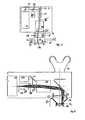
- FIG. 1 shows a schematic representation of the individual components of an exemplary embodiment of a laser system according to the invention.
- the processing apparatus 1 comprises as a beam source 11 a cavity-dumped fs oscillator.
- the laser beam 15 is coupled out via mirrors and a beam splitter 57 onto a beam widening optical system 21.
- the expanded laser beam 15 ' is then directed to a beam focusing device 24 via a beam deflection device such as a scanner in the XY direction. This is displaceable in the Z-axis and thus allows the displacement of the focus point by displacement of the beam focusing along the arrow Z.
- a focusing optical system with variable focal length can be used to move the focus position controlled in the Z direction.
- the focused laser spot 16 is thus directed onto the material 90 to be processed, which is held in position by a fixing device 32.
- the material 90 is here a contact lens to be processed.
- the spot 16 can also be aligned by moving the fixing device 32 in the direction XY 'or Z' on or in the material.
- the laser beam 15 generated by the beam source 11 is focused on the material 90.
- a focus diameter of a few micrometers can be achieved by focusing the laser beam 15 with a beam diameter of a few millimeters through optics with a few centimeters focal length.
- a focus diameter of three microns results when a laser beam of wavelength 1000 nm and a beam diameter of 10 mm is focused with a focal length of 50 mm.
- the laser beam 15 at the output of the beam source 11 has a smaller beam diameter than is necessary for optimal focusing.
- the beam diameter can be adapted to the requirements.
- a telescope in Galilei (diverging lens plus convergent lens) adjusted to infinity can be used as beam widening optics 21. This creates no intermediate focus, which could possibly lead to an optical breakthrough in air. Thus, the remaining laser energy is higher and the beam profile consistently good. Preference is given to the use of lens systems which lead to optimum imaging properties of the telescope. By adjusting the telescope and manufacturing fluctuations in the beam divergence of the beam source 11 can be compensated.
- the laser focus is scanned over or through the material.
- the laser focus or laser spot 16 is thus scanned three-dimensionally with micrometer accuracy.
- the expanded laser beam 15 ' is deflected perpendicular to the original beam direction by a deflector 23.
- the position of the focus 16 shifts to the focusing optics 24 perpendicular to the original beam direction.
- the focus can be moved in an area that is essentially flat and perpendicular to the laser beam direction (X / Y direction).
- the movement parallel to the beam direction (Z-direction) can take place on the one hand by moving the workpiece (see arrow Z ').
- the scanning algorithms are then preferably designed so that the workpiece must be moved only slowly and the fast scanning movements are performed by the deflection unit.
- the focusing optics can also be moved parallel to the direction of the laser beam (arrow Z) in order to reduce the focus in the Z direction.
- the second method is preferred because the patient generally can not be moved fast enough.
- the machined material 90 is fixed relative to the laser device in a fixing and adjusting device 32.
- the fixing device is adjusted vertically and parallel to the beam direction in order to place the pattern at the intended location in the material 90 can.
- mirror or mirror pairs 22 are provided.
- the nature of the mirrors is preferably chosen so that the processing laser beam does not destroy them, the mirrors are highly reflective for the wavelength of the processing laser and are sufficiently reflective for the pilot laser.
- the coating is chosen so that the mirror does not significantly extend the laser pulse duration.
- at least one of the mirrors will be a so-called "chirped mirror" with which the dispersion of all optics present in the beam path can be compensated in order to achieve optimally short pulses in the machining focus.
- FIG. 2 shows a further exemplary embodiment of the present laser processing apparatus with surgical microscope.
- the construction essentially corresponds to the structure in FIG. 1.
- the same parts are identified by the same reference numerals.
- a human eye is provided here.
- this laser device will be described in detail, with which precise cuts in the cornea of the human eye can be introduced.
- a circular surface which follows the curvature of the cornea and is centered to the optical axis of the eye to be cut with fs laser pulses within the cornea.
- a circular segment-shaped edge section from the circular surface to the outside of the cornea creates a corneal flap (flap), which can be folded to the side after the laser cut.
- Such a flap serves to prepare for a LASIK operation in which the thickness of the cornea is varied by laser ablation in such a way that refractive errors of the eye are compensated. So far, this cut is performed with a mechanical keratome, which requires a high degree of practice at the doctor and is fraught with risk.
- a refractive correction of the cornea can take place in the same operation by means of a further curved circular surface which, together with the first circular surface of the flap, encloses a lenticle which can be removed after opening the flap.
- the eye is pressed by a suction ring 32 to a contact glass 31, which is either flat, or preferably the curvature of the cornea is substantially adapted.
- the suction ring is firmly connected to the exit window of the laser device, which ensures a defined position of the cornea relative to the laser focus.
- the expanded femtosecond laser beam is focused with optics 24 in the cornea.
- a beam splitter which is highly reflective for the laser wavelength and transmitting for visible light, reflects the laser beam in the beam path of a surgical microscope, which is used for observation and centering of the eye.
- the focusing optics 24 forms a part of the microscope objective.
- a real intermediate image of the cornea can be generated, which can be viewed spatially with the stereo eyepiece 80.
- the beam deflection unit 23 deflects the expanded laser beam 15 perpendicular to its propagation direction.
- the laser focus can be directed to different points in the cornea.
- the depth of focus can be varied by displacing the focusing optics 24 along the optical axis or by adjusting the focal length of the focusing optics.
- the deflection unit travels circular paths.
- the circle radius is reduced from circular path to circular path and adjusted the repetition rate so; that a uniform spot distance is maintained.
- the depth of focus is adjusted from orbit to orbit so that the cut follows the curvature of the cornea. If astigmatic corrections of the sight (cylinder correction) are to be introduced, the depth of focus during the circular path can be moved up and down twice, so that a lenticle with a cylindrical lens portion is formed.
- the focal depth is slowly shifted from the flap bottom to the outside of the cornea at a fixed radius, so that a cylinder jacket is created.
- the laser beam must be interrupted to leave a "hang" on which the prepared flap is held. For this purpose, the decoupling of laser pulses from the beam source 11 is simply interrupted.
- the beam source 11 is a "cavity-dumped" femtosecond oscillator which is preferably directly diode pumped and thus simple and reliable.
- the emitted laser beam 15 is preferably expanded to a 1-2 cm beam diameter with a Galilean telescope. Kolinear to the expanded laser beam 15, a visible laser beam from a pilot laser 27 is superimposed, which is then scanned and focused together with the processing laser beam.
- the beam splitter 57 is transparent to the femtosecond laser wavelength and reflective to the pilot beam for this purpose.
- a laser device as described is used for a variety of applications (for example for refractive corrections of vision) in which cuts or structural transformations are made within the transparent components of the eye (cornea, lens, vitreous) and on the nontransparent parts such as sclera, iris, ciliary body to be, suitable.
- the invention far surpasses existing technologies
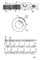
- FIG. 3 shows in the sub-representations 3 a to d application examples of cutting geometries which can be realized with the laser system according to the invention. These applications are only examples - any other geometries can be realized.
- the cohesion of the material 90 is repealed (photodisruption). In general, this is associated with local evaporation of the material.
- the cavitation bubble also referred to below as spot 16
- spot 16 the material structure is permanently or for a period of time lasting until at least the end of the processing period.
- the use of a hard-focused femtosecond laser or oscillator thus provides the most precise localization of the laser effect. In the sharply limited focus volume, this destroys the material structure, while in closely adjacent areas (even less than a micrometer away) there is generally no change in the material. This results in a high processing precision while preserving adjacent material regions.
- a large number of individual spots that dissolve the material structure are placed next to each other.
- the distance between adjacent spots should be on the order of the spot diameter at the end of the procedure.
- a predetermined volume e.g., a bore in the material
- FIG. 3 c an undercut in a transparent material 90 is shown. Since the radiation from the material 90 is not absorbed, contiguous pieces of material can be released from the material by placing spots on the cutting edge when it is adjacent to the surface.
- FIG. 4 schematically shows a detail of a possible scanning pattern, in which the individual spots 16 processed by individual laser pulses are arranged along paths which can be traversed continuously by the scanner.
- the focus is moved very quickly in at least one of three scan dimensions.
- the scanning algorithms are therefore preferably designed so that the spots are placed along paths that correspond to the natural movements of the deflection unit. The movement in the other two dimensions can then be relatively slow.
- the natural paths of the deflection unit may be, for example, circular paths that can run the deflection units with fixed circulating frequencies. This can be done for example by rotating optical elements in the deflection.
- the radius of the circular path and the depth of focus (Z-direction) are then the slowly variable scanning sizes.
- the repetition rate of the Lasers can be used particularly effectively if the rotational frequency of the circular paths is selected so that the full repetition rate of the beam source leads to the desired spot spacing b for the largest circular paths (B) to be traveled. If the circular paths are smaller in the radius (A) when the pattern is cut, the repetition rate of the source can be correspondingly reduced so that the optimum spot distance is again obtained. This adjustment of the repetition rate is readily possible with a suitable cavity-dumped oscillator.
- An adaptation of the rotational frequency to the repetition rate of the source may be technologically more difficult, in particular if this takes place continuously for each circular path (A, B). However, an adaptation of the rotational frequency in a few steps to the smaller circular paths may be advantageous for a reduction of the processing time.
- FIG. 5 shows possible sequences of laser pulses in and outside the laser resonator.
- the rotational frequency of the laser pulses in the oscillator 40 depends only on the resonator length and is predetermined for a particular beam source and is at resonator lengths of a few meters to 100 MHz.
- the principle of cavity dumping is to decouple a part of the pulse 45 circulating in the resonator at a specific time with a switchable optical element. In this case, a large part of the intracavity pulse energy leaves the beam source and is conducted as output laser pulse 46 into the beam deflection system.
- the pulse energy remaining in the resonator is amplified again to its saturation value after a number of circulations in the resonator 42 and can then be decoupled again.
- the decoupled laser pulses 46 thus have a lower repetition rate than the intracavity pulses 45.
- the maximum repetition rate is predetermined by the time until the saturation pulse energy is recovered after decoupling a laser pulse.
- the course of the intracavity pulse energy then corresponds approximately to the behavior shown in FIG. 5 as 42.
- the repetition rate can be reduced simply by decoupling 43, 44 only a certain time after reaching the saturation pulse energy.
- the time between two decoupled laser pulses (reciprocal of the repetition rate) can therefore be freely between infinite (zero repetition rate) and one in steps of the resonator circulation time Minimum (maximum repetition rate) can be set.
- Minimum maximum repetition rate
- the pulse repetition frequency of the deflection of the Strahlablenksystems can be adjusted.
- typical ratios of the decoupled repetition rate to the rotational frequency in the resonator of 1: 100-1: 1000 the number of laser spots placed per revolution of the deflection unit can thus be varied in minimal steps of 0.1-1% become.
- the spot distances on different orbits then scatter only by fractions of one percent.
- the present invention has provided a laser device which comprises a femtosecond beam source and preferably also means for beam shaping and guidance, a programmable beam deflection, beam focusing and a device for positioning and fixing the material or tissue to be processed.
- the device is preferably suitable for precise cutting and structuring with regard to laser pulse parameters, repetition rate and deflection speed and accuracy.
- the processing can also take place within the material.
- the material to be removed does not have to be completely removed by the laser, but by suitable cutting, coherent material regions can be removed intact.
- the cutting accuracy depends on the diameter of the laser focus and is in the micrometer and Submikrometer Scheme.
- the use of laser pulses with a pulse duration well below a picosecond reduces the collateral material or tissue damage almost completely and thus contributes significantly to the processing precision and allows in particular the medical treatment of sensitive tissues in vivo.
Landscapes
- Health & Medical Sciences (AREA)
- Optics & Photonics (AREA)
- Physics & Mathematics (AREA)
- Engineering & Computer Science (AREA)
- Ophthalmology & Optometry (AREA)
- Heart & Thoracic Surgery (AREA)
- Public Health (AREA)
- Veterinary Medicine (AREA)
- Surgery (AREA)
- Biomedical Technology (AREA)
- Nuclear Medicine, Radiotherapy & Molecular Imaging (AREA)
- Vascular Medicine (AREA)
- Life Sciences & Earth Sciences (AREA)
- Animal Behavior & Ethology (AREA)
- General Health & Medical Sciences (AREA)
- Plasma & Fusion (AREA)
- Mechanical Engineering (AREA)
- Transplantation (AREA)
- Laser Surgery Devices (AREA)
- Laser Beam Processing (AREA)
- Radiation-Therapy Devices (AREA)
- Lasers (AREA)
- Cosmetics (AREA)
Claims (7)
- Dispositif (1) pour le traitement précis de matière (90), notamment de matière organique, comprenant un système laser (10) pulsé à l'aide d'un oscillateur fs à vidage de cavité (11) (cavity dumped) servant de source de faisceau (15), caractérisé en ce que les dispositifs à faisceau (20) permettent d'appliquer le faisceau de travail de la source de faisceau à une vitesse de répétition prédéterminée dans des moules de forme prédéterminée à un intervalle prédéterminé ou dans la matière (90) tandis que la vitesse de répétition peut être modifiée.
- Dispositif selon la revendication 1, caractérisé en ce que les dispositifs à faisceau (20) sont prévus pour la formation du faisceau (21) et/ou pour le guidage du faisceau (22) et/ou pour la déviation du faisceau (23) et/ou pour la focalisation du faisceau (24).
- Dispositif selon la revendication 2, caractérisé en ce que les dispositifs à faisceau (20) peuvent être programmés.
- Dispositif selon l'une quelconque des revendications précédentes, caractérisé en ce que l'on prévoit des dispositifs de maintien (30) pour le positionnement (31) et/ou la fixation (32) de la matière (90) à traiter.
- Dispositif selon l'une quelconque des revendications précédentes, caractérisé en ce que l'oscillateur fs à vidage de cavité (11) permet de fournir des impulsions laser allant de 100 nJ à 100 µJ, de préférence une énergie d'impulsion de 1 µJ.
- Dispositif selon l'une quelconque des revendications précédentes, caractérisé en ce que l'oscillateur fs à vidage de cavité (11) permet de fournir des impulsions laser à vitesse de répétition allant de 10 kHz à 10 MHz.
- Dispositif selon l'une quelconque des revendications précédentes, caractérisé en ce que la vitesse de répétition va de 50 kHz à 1 MHz, notamment de 100 kHz à 500 kHz.
Priority Applications (2)
| Application Number | Priority Date | Filing Date | Title |
|---|---|---|---|
| EP10012895.8A EP2352210B1 (fr) | 2002-01-18 | 2003-01-17 | Système à laser femtosecondes pour le traitement précis de matériaux et de tissus |
| EP06018980A EP1742311B1 (fr) | 2002-01-18 | 2003-01-17 | Système laser à femtosecondes pour le traitement précis de matière et de tissus |
Applications Claiming Priority (3)
| Application Number | Priority Date | Filing Date | Title |
|---|---|---|---|
| DE10202036A DE10202036A1 (de) | 2002-01-18 | 2002-01-18 | Femtosekunden Lasersystem zur präzisen Bearbeitung von Material und Gewebe |
| DE10202036 | 2002-01-18 | ||
| PCT/EP2003/000446 WO2003059563A2 (fr) | 2002-01-18 | 2003-01-17 | Systeme laser a femtosecondes pour le traitement precis de matiere et de tissus |
Related Child Applications (2)
| Application Number | Title | Priority Date | Filing Date |
|---|---|---|---|
| EP06018980A Division EP1742311B1 (fr) | 2002-01-18 | 2003-01-17 | Système laser à femtosecondes pour le traitement précis de matière et de tissus |
| EP10012895.8A Division EP2352210B1 (fr) | 2002-01-18 | 2003-01-17 | Système à laser femtosecondes pour le traitement précis de matériaux et de tissus |
Publications (2)
| Publication Number | Publication Date |
|---|---|
| EP1470623A2 EP1470623A2 (fr) | 2004-10-27 |
| EP1470623B1 true EP1470623B1 (fr) | 2006-09-13 |
Family
ID=7712606
Family Applications (3)
| Application Number | Title | Priority Date | Filing Date |
|---|---|---|---|
| EP06018980A Expired - Lifetime EP1742311B1 (fr) | 2002-01-18 | 2003-01-17 | Système laser à femtosecondes pour le traitement précis de matière et de tissus |
| EP10012895.8A Expired - Lifetime EP2352210B1 (fr) | 2002-01-18 | 2003-01-17 | Système à laser femtosecondes pour le traitement précis de matériaux et de tissus |
| EP03704425A Expired - Lifetime EP1470623B1 (fr) | 2002-01-18 | 2003-01-17 | Systeme laser a femtosecondes pour le traitement precis de matiere et de tissus |
Family Applications Before (2)
| Application Number | Title | Priority Date | Filing Date |
|---|---|---|---|
| EP06018980A Expired - Lifetime EP1742311B1 (fr) | 2002-01-18 | 2003-01-17 | Système laser à femtosecondes pour le traitement précis de matière et de tissus |
| EP10012895.8A Expired - Lifetime EP2352210B1 (fr) | 2002-01-18 | 2003-01-17 | Système à laser femtosecondes pour le traitement précis de matériaux et de tissus |
Country Status (7)
| Country | Link |
|---|---|
| US (2) | US8585686B2 (fr) |
| EP (3) | EP1742311B1 (fr) |
| JP (2) | JP2005514211A (fr) |
| AT (2) | ATE339786T1 (fr) |
| AU (1) | AU2003206747A1 (fr) |
| DE (3) | DE10202036A1 (fr) |
| WO (1) | WO2003059563A2 (fr) |
Cited By (1)
| Publication number | Priority date | Publication date | Assignee | Title |
|---|---|---|---|---|
| US11353714B2 (en) | 2018-09-10 | 2022-06-07 | Matthew David TREISER | Laser system delivering ultra-short pulses along multiple beam delivery paths |
Families Citing this family (125)
| Publication number | Priority date | Publication date | Assignee | Title |
|---|---|---|---|---|
| US7583710B2 (en) | 2001-01-30 | 2009-09-01 | Board Of Trustees Operating Michigan State University | Laser and environmental monitoring system |
| US7450618B2 (en) | 2001-01-30 | 2008-11-11 | Board Of Trustees Operating Michigan State University | Laser system using ultrashort laser pulses |
| US7567596B2 (en) | 2001-01-30 | 2009-07-28 | Board Of Trustees Of Michigan State University | Control system and apparatus for use with ultra-fast laser |
| US7973936B2 (en) | 2001-01-30 | 2011-07-05 | Board Of Trustees Of Michigan State University | Control system and apparatus for use with ultra-fast laser |
| US8208505B2 (en) | 2001-01-30 | 2012-06-26 | Board Of Trustees Of Michigan State University | Laser system employing harmonic generation |
| DE10202036A1 (de) * | 2002-01-18 | 2003-07-31 | Zeiss Carl Meditec Ag | Femtosekunden Lasersystem zur präzisen Bearbeitung von Material und Gewebe |
| DE10309971A1 (de) * | 2003-03-07 | 2004-09-16 | Leica Microsystems (Schweiz) Ag | Operationsmikroskop mit einer Objektfeldbeleuchtung |
| US20040188401A1 (en) * | 2003-03-28 | 2004-09-30 | Sadao Mori | Laser processing apparatus |
| US7361171B2 (en) | 2003-05-20 | 2008-04-22 | Raydiance, Inc. | Man-portable optical ablation system |
| US7351241B2 (en) * | 2003-06-02 | 2008-04-01 | Carl Zeiss Meditec Ag | Method and apparatus for precision working of material |
| DE10334110A1 (de) | 2003-07-25 | 2005-02-17 | Carl Zeiss Meditec Ag | Vorrichtung und Verfahren zum Ausbilden gekrümmter Schnittflächen in einem transparenten Material |
| US8921733B2 (en) | 2003-08-11 | 2014-12-30 | Raydiance, Inc. | Methods and systems for trimming circuits |
| US8173929B1 (en) | 2003-08-11 | 2012-05-08 | Raydiance, Inc. | Methods and systems for trimming circuits |
| US7367969B2 (en) * | 2003-08-11 | 2008-05-06 | Raydiance, Inc. | Ablative material removal with a preset removal rate or volume or depth |
| US9022037B2 (en) | 2003-08-11 | 2015-05-05 | Raydiance, Inc. | Laser ablation method and apparatus having a feedback loop and control unit |
| DE10350349B3 (de) * | 2003-10-29 | 2004-12-23 | Siemens Ag | Verfahren und Vorrichtung zur Bearbeitung eines Substrats, insbesondere einer elektrischen Leiterplatte, mittels Laserstrahlung |
| DE10358927B4 (de) * | 2003-12-16 | 2021-09-09 | Carl Zeiss Meditec Ag | Laservorrichtung und Verfahren zur Materialbearbeitung mittels Laserstrahlung |
| US8186357B2 (en) * | 2004-01-23 | 2012-05-29 | Rowiak Gmbh | Control device for a surgical laser |
| US8394084B2 (en) * | 2005-01-10 | 2013-03-12 | Optimedica Corporation | Apparatus for patterned plasma-mediated laser trephination of the lens capsule and three dimensional phaco-segmentation |
| US8633437B2 (en) | 2005-02-14 | 2014-01-21 | Board Of Trustees Of Michigan State University | Ultra-fast laser system |
| DE102005013949A1 (de) * | 2005-03-26 | 2006-09-28 | Carl Zeiss Meditec Ag | Scanvorrichtung |
| DE102005027355A1 (de) * | 2005-06-13 | 2006-12-14 | Femtotechnologies Gmbh | Verfahren zum Bearbeiten eines organischen Materials |
| US8135050B1 (en) | 2005-07-19 | 2012-03-13 | Raydiance, Inc. | Automated polarization correction |
| US20070075060A1 (en) * | 2005-09-30 | 2007-04-05 | Shedlov Matthew S | Method of manufacturing a medical device from a workpiece using a pulsed beam of radiation or particles having an adjustable pulse frequency |
| US20080065052A1 (en) * | 2005-10-14 | 2008-03-13 | Carl Zeiss Meditec Ag | Device and method for material processing by means of laser radiation |
| US8553735B2 (en) * | 2005-10-14 | 2013-10-08 | Carl Zeiss Meditec Ag | Device and method for material processing by means of laser radiation |
| DE102005049281A1 (de) * | 2005-10-14 | 2007-04-19 | Carl Zeiss Meditec Ag | Vorrichtung und Verfahren zur Materialbearbeitung mittels Laserstrahlung |
| DE102005056958A1 (de) * | 2005-11-29 | 2007-06-06 | Rowiak Gmbh | Verfahren und Vorrichtung zum Bearbeiten eines Werkstücks |
| US8618470B2 (en) | 2005-11-30 | 2013-12-31 | Board Of Trustees Of Michigan State University | Laser based identification of molecular characteristics |
| US8189971B1 (en) | 2006-01-23 | 2012-05-29 | Raydiance, Inc. | Dispersion compensation in a chirped pulse amplification system |
| US8232687B2 (en) | 2006-04-26 | 2012-07-31 | Raydiance, Inc. | Intelligent laser interlock system |
| US9130344B2 (en) | 2006-01-23 | 2015-09-08 | Raydiance, Inc. | Automated laser tuning |
| US7444049B1 (en) | 2006-01-23 | 2008-10-28 | Raydiance, Inc. | Pulse stretcher and compressor including a multi-pass Bragg grating |
| ES2411480T3 (es) * | 2006-03-15 | 2013-07-05 | Wavelight Gmbh | Programa de control para el control temporal y espacial de impulsos láser |
| US7822347B1 (en) | 2006-03-28 | 2010-10-26 | Raydiance, Inc. | Active tuning of temporal dispersion in an ultrashort pulse laser system |
| WO2007145702A2 (fr) | 2006-04-10 | 2007-12-21 | Board Of Trustees Of Michigan State University | Système d'usinage par laser |
| DE102006046925A1 (de) * | 2006-09-28 | 2008-04-03 | Jenlab Gmbh | Verfahren und Anordnung zur Laser-Endoskopie für die Mikrobearbeitung |
| WO2009033110A2 (fr) * | 2007-09-05 | 2009-03-12 | Lensx Lasers, Inc. | Blindage de protection induit par laser en chirurgie laser |
| EP2194903B1 (fr) * | 2007-09-06 | 2017-10-25 | Alcon LenSx, Inc. | Ciblage précis d'une photodisruption chirurgicale |
| US9456925B2 (en) * | 2007-09-06 | 2016-10-04 | Alcon Lensx, Inc. | Photodisruptive laser treatment of the crystalline lens |
| US20090149840A1 (en) * | 2007-09-06 | 2009-06-11 | Kurtz Ronald M | Photodisruptive Treatment of Crystalline Lens |
| JP2010538704A (ja) * | 2007-09-10 | 2010-12-16 | アルコン レンゼックス, インコーポレーテッド | 重力場における有効なレーザ光破壊手術 |
| JP2010538770A (ja) * | 2007-09-18 | 2010-12-16 | アルコン レンゼックス, インコーポレーテッド | 統合された白内障手術のための方法及び装置 |
| US20090137991A1 (en) * | 2007-09-18 | 2009-05-28 | Kurtz Ronald M | Methods and Apparatus for Laser Treatment of the Crystalline Lens |
| DE102007048780B4 (de) * | 2007-10-10 | 2018-02-08 | Landesstiftung Baden-Württemberg gGmbH | Strahlumlenkvorrichtung und Verfahren zum rasterartigen Überstreichen einer Oberfläche mit einem Lichtstrahl |
| WO2009059251A2 (fr) * | 2007-11-02 | 2009-05-07 | Lensx Lasers, Inc. | Procédés et appareils d'amélioration des performances optiques après une opération ophtalmologique |
| US7903326B2 (en) | 2007-11-30 | 2011-03-08 | Radiance, Inc. | Static phase mask for high-order spectral phase control in a hybrid chirped pulse amplifier system |
| DE102007058105A1 (de) * | 2007-12-03 | 2009-06-10 | Carl Zeiss Smt Ag | Vorrichtung und Verfahren zur Bearbeitung von optischen Elementen mittels Laserablation |
| US8311069B2 (en) | 2007-12-21 | 2012-11-13 | Board Of Trustees Of Michigan State University | Direct ultrashort laser system |
| PT3363415T (pt) | 2008-01-09 | 2019-11-05 | Alcon Lensx Inc | Fragmentação curva de tecido por laser fotodisruptivo |
| US8740888B2 (en) * | 2008-01-18 | 2014-06-03 | Technolas Perfect Vision Gmbh | Computer control for bio-mechanical alteration of the cornea |
| DE102008017772B4 (de) * | 2008-04-04 | 2021-10-07 | Carl Zeiss Meditec Ag | Vorrichtung zum Ausbilden von Schnittflächen in einem transparentem Material |
| WO2009129483A1 (fr) * | 2008-04-17 | 2009-10-22 | Musculoskeletal Transplant Foundation | Applications de laser à impulsions ultrabrèves |
| DE502008001155D1 (de) * | 2008-05-02 | 2010-09-30 | Leister Process Tech | Verfahren und Laservorrichtung zum Bearbeiten und/oder Verbinden von Werkstücken mittels Laserstrahlung mit Leistungswirk- und Pilotlaser und mindestens einem diffraktiven optischen Element |
| US20090299345A1 (en) * | 2008-05-27 | 2009-12-03 | Bille Josef F | System and method for reshaping a cornea using a combination of liob and structural change procedures |
| US10182942B2 (en) | 2008-06-05 | 2019-01-22 | Carl Zeiss Meditec Ag | Ophthalmological laser system and operating method |
| DE102008027358A1 (de) * | 2008-06-05 | 2009-12-10 | Carl Zeiss Meditec Ag | Ophthalmologisches Lasersystem und Betriebsverfahren |
| US8500723B2 (en) | 2008-07-25 | 2013-08-06 | Lensar, Inc. | Liquid filled index matching device for ophthalmic laser procedures |
| US8480659B2 (en) | 2008-07-25 | 2013-07-09 | Lensar, Inc. | Method and system for removal and replacement of lens material from the lens of an eye |
| US8125704B2 (en) | 2008-08-18 | 2012-02-28 | Raydiance, Inc. | Systems and methods for controlling a pulsed laser by combining laser signals |
| GB0816308D0 (en) | 2008-09-05 | 2008-10-15 | Mtt Technologies Ltd | Optical module |
| US8675699B2 (en) | 2009-01-23 | 2014-03-18 | Board Of Trustees Of Michigan State University | Laser pulse synthesis system |
| WO2010141128A2 (fr) | 2009-03-05 | 2010-12-09 | Board Of Trustees Of Michigan State University | Système d'amplification laser |
| DE102009012873B4 (de) | 2009-03-12 | 2021-08-19 | Carl Zeiss Meditec Ag | Ophthalmologisches Lasersystem und Steuereinheit |
| US8758332B2 (en) | 2009-07-24 | 2014-06-24 | Lensar, Inc. | Laser system and method for performing and sealing corneal incisions in the eye |
| JP2013500086A (ja) | 2009-07-24 | 2013-01-07 | レンサー, インク. | Ladarを利用した手順を眼の水晶体に実施するシステムおよび方法 |
| US8617146B2 (en) | 2009-07-24 | 2013-12-31 | Lensar, Inc. | Laser system and method for correction of induced astigmatism |
| WO2011011727A1 (fr) | 2009-07-24 | 2011-01-27 | Lensar, Inc. | Système et procédé pour émettre des motifs de tir laser vers le cristallin |
| US8382745B2 (en) | 2009-07-24 | 2013-02-26 | Lensar, Inc. | Laser system and method for astigmatic corrections in association with cataract treatment |
| ATE549946T1 (de) * | 2009-08-03 | 2012-04-15 | Kraft Foods R & D Inc | Verfahren zur verarbeitung von nahrungsmittelmaterial mit einem impulslaserstrahl |
| WO2011035063A1 (fr) * | 2009-09-18 | 2011-03-24 | Amo Development, Llc | Enregistrement d'un volet cornéen avec mesure ophtalmique et/ou des données de traitement pour lasik et autres procédures |
| EP2531089B1 (fr) | 2010-02-01 | 2023-04-05 | LENSAR, Inc. | Alignement fondé sur des images de purkinje d'un anneau d'aspiration dans des applications ophtalmiques |
| US8630322B2 (en) | 2010-03-01 | 2014-01-14 | Board Of Trustees Of Michigan State University | Laser system for output manipulation |
| EP2549957B1 (fr) | 2010-03-23 | 2019-01-30 | Edwards Lifesciences Corporation | Méthodes de conditionnement d'un tissu bioprothétique en feuillets |
| DE102011103181A1 (de) | 2010-06-03 | 2011-12-29 | Carl Zeiss Meditec Ag | Vorrichtung und Verfahren zur Glaskörperchirurgie |
| WO2012021748A1 (fr) | 2010-08-12 | 2012-02-16 | Raydiance, Inc. | Micro-usinage au laser de tube polymère |
| US9114482B2 (en) | 2010-09-16 | 2015-08-25 | Raydiance, Inc. | Laser based processing of layered materials |
| USD695408S1 (en) | 2010-10-15 | 2013-12-10 | Lensar, Inc. | Laser system for treatment of the eye |
| USD694890S1 (en) | 2010-10-15 | 2013-12-03 | Lensar, Inc. | Laser system for treatment of the eye |
| WO2012051490A1 (fr) | 2010-10-15 | 2012-04-19 | Lensar, Inc. | Système et procédé d'éclairage commandé par balayage de structures dans un oeil |
| KR20140007913A (ko) * | 2011-02-15 | 2014-01-20 | 웨이브라이트 게엠베하 | 인간의 눈에 각막의 인공 기관의 이식을 지원하는 장치 및 이러한 이식을 실행하는 방법 |
| US10463541B2 (en) | 2011-03-25 | 2019-11-05 | Lensar, Inc. | System and method for correcting astigmatism using multiple paired arcuate laser generated corneal incisions |
| EP2695016B1 (fr) * | 2011-04-01 | 2017-05-03 | Lensar, Inc. | Système pour des incisions de lentilles cornéenne et cristalline générées par laser à l'aide d'un système optique à f/ variable avec interface de contact asphérique avec la cornée ou optiques rotatives et adaptatives |
| US20120330291A1 (en) * | 2011-06-24 | 2012-12-27 | The Regents Of The University Of California | Nonlinear optical photodynamic therapy (nlo-pdt) of the cornea |
| US9095414B2 (en) * | 2011-06-24 | 2015-08-04 | The Regents Of The University Of California | Nonlinear optical photodynamic therapy (NLO-PDT) of the cornea |
| EP2565994B1 (fr) | 2011-09-05 | 2014-02-12 | ALLTEC Angewandte Laserlicht Technologie Gesellschaft mit beschränkter Haftung | Dispositif laser et procédé de marquage d'un objet |
| ES2544034T3 (es) | 2011-09-05 | 2015-08-27 | ALLTEC Angewandte Laserlicht Technologie Gesellschaft mit beschränkter Haftung | Aparato de marcado con al menos un láser de gas y un termodisipador |
| ES2530069T3 (es) * | 2011-09-05 | 2015-02-26 | ALLTEC Angewandte Laserlicht Technologie Gesellschaft mit beschränkter Haftung | Aparato de marcado con una pluralidad de láseres y un dispositivo de desviación de combinación |
| DK2565673T3 (da) | 2011-09-05 | 2014-01-06 | Alltec Angewandte Laserlicht Technologie Gmbh | Indretning og fremgangsmåde til markering af et objekt ved hjælp af en laserstråle |
| EP2564972B1 (fr) * | 2011-09-05 | 2015-08-26 | ALLTEC Angewandte Laserlicht Technologie Gesellschaft mit beschränkter Haftung | Appareil de marquage avec plusieurs lasers et des moyens de déflection et de focalisation pour chaque faisceau lser |
| DK2565996T3 (da) | 2011-09-05 | 2014-01-13 | Alltec Angewandte Laserlicht Technologie Gmbh | Laserindretning med en laserenhed og en fluidbeholder til en køleindretning af laserenheden |
| EP2564974B1 (fr) * | 2011-09-05 | 2015-06-17 | ALLTEC Angewandte Laserlicht Technologie Gesellschaft mit beschränkter Haftung | Appareil de marquage avec une pluralité de lasers gaz ayant des tubes résonateurs et des déflecteurs ajustables individuellement |
| DK2564975T3 (en) * | 2011-09-05 | 2015-01-12 | Alltec Angewandte Laserlicht Technologie Ges Mit Beschränkter Haftung | Selection apparatus with a plurality of lasers and sets of deflecting agents that can be individually adjusted |
| DE102011116759A1 (de) | 2011-10-20 | 2013-04-25 | Carl Zeiss Meditec Ag | Ophthalmologisches Lasersystem und Verfahren zum Durchtrennen von Augengewebe |
| DE102011085047A1 (de) * | 2011-10-21 | 2013-04-25 | Carl Zeiss Meditec Ag | Erzeugung von Schnitten in einem transparenten Material mittels optischer Strahlung |
| DE102011085046A1 (de) | 2011-10-21 | 2013-04-25 | Carl Zeiss Meditec Ag | Erzeugung von Schnittflächen in einem transparenten Material mittels optischer Strahlung |
| CA2861139C (fr) | 2012-01-18 | 2017-07-11 | Wavelight Gmbh | Reglage d'energie laser en fonction d'une densite optique |
| WO2013126653A1 (fr) * | 2012-02-22 | 2013-08-29 | Amo Development, Llc | Systèmes et procédés pour lentilles préformées |
| CN102615436A (zh) * | 2012-04-09 | 2012-08-01 | 镇江大成新能源有限公司 | 薄膜太阳能电池飞秒激光刻蚀工艺过程测控方法 |
| CN102626831A (zh) * | 2012-04-09 | 2012-08-08 | 镇江大成新能源有限公司 | 薄膜太阳能电池飞秒激光刻蚀设备 |
| EP2705812A1 (fr) * | 2012-09-05 | 2014-03-12 | Universität zu Lübeck | Dispositif de découpage laser à l'intérieur d'un matériau transparent |
| US9601897B2 (en) * | 2013-01-09 | 2017-03-21 | Universitaet Stuttgart | Optical rotating device for injecting a laser beam and method for positioning a laser beam |
| DE102013204496A1 (de) | 2013-03-14 | 2014-09-18 | Carl Zeiss Meditec Ag | Erzeugung gekrümmter Schnitte im Inneren der Augenhornhaut |
| AU2014228568B2 (en) | 2013-03-14 | 2018-06-14 | Amo Development, Llc | Laser capsulovitreotomy |
| US9048632B1 (en) * | 2013-03-15 | 2015-06-02 | Board Of Trustees Of Michigan State University | Ultrafast laser apparatus |
| DE102013008269C5 (de) * | 2013-05-15 | 2019-01-24 | Precitec Optronik Gmbh | Bearbeitungskopf für eine Laserbearbeitungsvorrichtung |
| JP5928516B2 (ja) * | 2014-04-07 | 2016-06-01 | 株式会社ニデック | 眼科用レーザ治療装置 |
| FR3026940B1 (fr) | 2014-10-08 | 2021-09-03 | Univ Jean Monnet | Dispositif et procede pour la decoupe d'une cornee ou d'un cristallin |
| EP3261596B1 (fr) * | 2015-02-26 | 2021-06-16 | AMO Development, LLC | Systèmes pour photokératectomie réfractive au laser femtoseconde |
| DE102015112151A1 (de) * | 2015-07-24 | 2017-02-09 | Lpkf Laser & Electronics Ag | Verfahren und Vorrichtung zur Laserbearbeitung eines Substrates mit mehrfacher Ablenkung einer Laserstrahlung |
| CN108024831A (zh) | 2015-10-23 | 2018-05-11 | 纽约市哥伦比亚大学理事会 | 由激光诱导的组织中的胶原交联 |
| EP3377253B1 (fr) | 2015-11-16 | 2023-03-01 | Renishaw PLC | Module pour appareil de fabrication additive |
| US10219948B2 (en) | 2016-02-24 | 2019-03-05 | Perfect Ip, Llc | Ophthalmic laser treatment system and method |
| EP3909552B1 (fr) | 2016-04-06 | 2023-03-08 | Keranova | Système optique de focalisation d'un appareil de découpe incluant un modulateur spatial de lumière |
| WO2017214604A1 (fr) | 2016-06-10 | 2017-12-14 | The Trustees Of Columbia University In The City Of New York | Dispositifs, procédés et systèmes de détection de caractéristiques tissulaires du collagène |
| DE102017002986B4 (de) * | 2016-12-13 | 2019-08-29 | AIXLens GmbH | Verfahren zur Herstellung einer transmitiven Optik und Intraokularlinse |
| US11666481B1 (en) | 2017-12-01 | 2023-06-06 | The Trustees Of Columbia University In The City Of New York | Diagnosis and treatment of collagen-containing tissues |
| CA3079702A1 (fr) * | 2017-12-12 | 2019-06-20 | Alcon Inc. | Interface patient pour chirurgie ophtalmique |
| TW202114308A (zh) * | 2019-05-21 | 2021-04-01 | 日商索尼股份有限公司 | 被動q開關雷射裝置、控制方法及雷射加工裝置 |
| CN111192307B (zh) * | 2019-12-20 | 2023-03-21 | 广西柳州联耕科技有限公司 | 基于激光切割三维零部件的自适应纠偏方法 |
| US11612315B2 (en) | 2020-04-09 | 2023-03-28 | Vialase, Inc. | Alignment and diagnostic device and methods for imaging and surgery at the irido-corneal angle of the eye |
| DE102020112583B4 (de) * | 2020-05-08 | 2024-02-15 | Schwind Eye-Tech-Solutions Gmbh | Verfahren zur Steuerung eines augenchirurgischen Lasers und Behandlungsvorrichtung |
| CN115673453A (zh) * | 2021-07-22 | 2023-02-03 | 台达电子工业股份有限公司 | 激光焊锡系统及其光束整形方法 |
| US12002567B2 (en) | 2021-11-29 | 2024-06-04 | Vialase, Inc. | System and method for laser treatment of ocular tissue based on patient biometric data and apparatus and method for determining laser energy based on an anatomical model |
| US20240058169A1 (en) * | 2022-08-17 | 2024-02-22 | Vialase, Inc. | System and method for accessing different tissue targets of the eye |
Family Cites Families (41)
| Publication number | Priority date | Publication date | Assignee | Title |
|---|---|---|---|---|
| AU606315B2 (en) * | 1985-09-12 | 1991-02-07 | Summit Technology, Inc. | Surface erosion using lasers |
| US4646308A (en) * | 1985-09-30 | 1987-02-24 | Spectra-Physics, Inc. | Synchronously pumped dye laser using ultrashort pump pulses |
| US4901717A (en) | 1987-01-05 | 1990-02-20 | Moore Robert R | Tendon leader |
| JP2597845B2 (ja) * | 1987-06-09 | 1997-04-09 | 浜松ホトニクス株式会社 | 高繰り返しパルスレーザー装置 |
| US4901718A (en) * | 1988-02-02 | 1990-02-20 | Intelligent Surgical Lasers | 3-Dimensional laser beam guidance system |
| US4907586A (en) * | 1988-03-31 | 1990-03-13 | Intelligent Surgical Lasers | Method for reshaping the eye |
| US5119815A (en) * | 1988-12-21 | 1992-06-09 | Nim, Incorporated | Apparatus for determining the concentration of a tissue pigment of known absorbance, in vivo, using the decay characteristics of scintered electromagnetic radiation |
| JPH05102618A (ja) | 1991-10-04 | 1993-04-23 | Toshiba Corp | 短パルスレーザ発生装置 |
| US6325792B1 (en) * | 1991-11-06 | 2001-12-04 | Casimir A. Swinger | Ophthalmic surgical laser and method |
| US5984916A (en) * | 1993-04-20 | 1999-11-16 | Lai; Shui T. | Ophthalmic surgical laser and method |
| US5520679A (en) * | 1992-12-03 | 1996-05-28 | Lasersight, Inc. | Ophthalmic surgery method using non-contact scanning laser |
| US5336215A (en) * | 1993-01-22 | 1994-08-09 | Intelligent Surgical Lasers | Eye stabilizing mechanism for use in ophthalmic laser surgery |
| US5656186A (en) * | 1994-04-08 | 1997-08-12 | The Regents Of The University Of Michigan | Method for controlling configuration of laser induced breakdown and ablation |
| US6016324A (en) * | 1994-08-24 | 2000-01-18 | Jmar Research, Inc. | Short pulse laser system |
| JPH10134345A (ja) * | 1995-10-23 | 1998-05-22 | Mitsubishi Chem Corp | 磁気記録媒体およびその製造方法 |
| US5720894A (en) * | 1996-01-11 | 1998-02-24 | The Regents Of The University Of California | Ultrashort pulse high repetition rate laser system for biological tissue processing |
| EP0951260B1 (fr) * | 1996-10-26 | 2002-09-18 | Asclepion-Meditec AG | Procede et dispositif de faconnage de surfaces |
| DE19727573C1 (de) * | 1996-10-26 | 1998-05-20 | Aesculap Meditec Gmbh | Vorrichtung und Verfahren zur Formgebung von Oberflächen, insbesondere von Linsen |
| JPH10166167A (ja) * | 1996-12-03 | 1998-06-23 | Komatsu Ltd | レーザマーキング方法及び装置 |
| US5870421A (en) * | 1997-05-12 | 1999-02-09 | Dahm; Jonathan S. | Short pulsewidth, high pulse repetition frequency laser system |
| CA2206938C (fr) * | 1997-06-02 | 2005-07-26 | Luc Lafond | Outil manuel d'application de bandes avec appareil a former des coins |
| JP3208730B2 (ja) * | 1998-01-16 | 2001-09-17 | 住友重機械工業株式会社 | 光透過性材料のマーキング方法 |
| US7128737B1 (en) | 1997-10-22 | 2006-10-31 | Carl Zeiss Meditec Ag | Object figuring device |
| JPH11151584A (ja) * | 1997-11-17 | 1999-06-08 | Toshiba Corp | レーザ加工方法及びその装置 |
| AT408163B (de) * | 1998-02-25 | 2001-09-25 | Wintner Ernst Dr | Lasersystem zur erzeugung ultrakurzer lichtimpulse |
| DE19831674A1 (de) * | 1998-07-15 | 2000-01-20 | Laserforum Gmbh Forum Fuer Las | Refraktivchirurgische Augenhalterung |
| US6254595B1 (en) * | 1998-10-15 | 2001-07-03 | Intralase Corporation | Corneal aplanation device |
| US6623476B2 (en) * | 1998-10-15 | 2003-09-23 | Intralase Corp. | Device and method for reducing corneal induced aberrations during ophthalmic laser surgery |
| US6146375A (en) * | 1998-12-02 | 2000-11-14 | The University Of Michigan | Device and method for internal surface sclerostomy |
| US6333485B1 (en) * | 1998-12-11 | 2001-12-25 | International Business Machines Corporation | Method for minimizing sample damage during the ablation of material using a focused ultrashort pulsed beam |
| US6573026B1 (en) * | 1999-07-29 | 2003-06-03 | Corning Incorporated | Femtosecond laser writing of glass, including borosilicate, sulfide, and lead glasses |
| US6999491B2 (en) * | 1999-10-15 | 2006-02-14 | Jmar Research, Inc. | High intensity and high power solid state laser amplifying system and method |
| JP2001232487A (ja) | 1999-11-30 | 2001-08-28 | Canon Inc | レーザ加工装置とレーザ加工方法、および該レーザ加工装置または方法によって加工するインクジェット記録ヘッドの製造方法と該製造方法によるインクジェット記録ヘッド |
| JP3982136B2 (ja) * | 2000-02-04 | 2007-09-26 | セイコーエプソン株式会社 | レーザ加工方法及びその装置 |
| AUPQ555400A0 (en) * | 2000-02-11 | 2000-03-02 | Macquarie Research Limited | Laser system and methods |
| JP3779119B2 (ja) | 2000-02-29 | 2006-05-24 | 独立行政法人科学技術振興機構 | 高強度超短パルスレーザー加工方法 |
| US6603600B2 (en) * | 2001-11-21 | 2003-08-05 | Coherent, Inc. | Chirped pulse amplification method and apparatus |
| US20030099452A1 (en) * | 2001-11-28 | 2003-05-29 | Borrelli Nicholas F. | Manipulating the size of waveguides written into substrates using femtosecond laser pulses |
| DE10202036A1 (de) * | 2002-01-18 | 2003-07-31 | Zeiss Carl Meditec Ag | Femtosekunden Lasersystem zur präzisen Bearbeitung von Material und Gewebe |
| US6964659B2 (en) * | 2002-05-30 | 2005-11-15 | Visx, Incorporated | Thermal modeling for reduction of refractive laser surgery times |
| US7223670B2 (en) | 2004-08-20 | 2007-05-29 | International Business Machines Corporation | DUV laser annealing and stabilization of SiCOH films |
-
2002
- 2002-01-18 DE DE10202036A patent/DE10202036A1/de not_active Withdrawn
-
2003
- 2003-01-17 EP EP06018980A patent/EP1742311B1/fr not_active Expired - Lifetime
- 2003-01-17 EP EP10012895.8A patent/EP2352210B1/fr not_active Expired - Lifetime
- 2003-01-17 WO PCT/EP2003/000446 patent/WO2003059563A2/fr active IP Right Grant
- 2003-01-17 AT AT03704425T patent/ATE339786T1/de not_active IP Right Cessation
- 2003-01-17 JP JP2003559712A patent/JP2005514211A/ja active Pending
- 2003-01-17 DE DE50305026T patent/DE50305026D1/de not_active Expired - Lifetime
- 2003-01-17 AT AT06018980T patent/ATE501535T1/de active
- 2003-01-17 DE DE50313535T patent/DE50313535D1/de not_active Expired - Lifetime
- 2003-01-17 EP EP03704425A patent/EP1470623B1/fr not_active Expired - Lifetime
- 2003-01-17 AU AU2003206747A patent/AU2003206747A1/en not_active Abandoned
- 2003-01-17 US US10/501,679 patent/US8585686B2/en active Active
-
2011
- 2011-11-21 JP JP2011253954A patent/JP5658649B2/ja not_active Expired - Lifetime
-
2013
- 2013-10-23 US US14/060,686 patent/US10123906B2/en not_active Expired - Lifetime
Cited By (2)
| Publication number | Priority date | Publication date | Assignee | Title |
|---|---|---|---|---|
| US11353714B2 (en) | 2018-09-10 | 2022-06-07 | Matthew David TREISER | Laser system delivering ultra-short pulses along multiple beam delivery paths |
| US11782283B2 (en) | 2018-09-10 | 2023-10-10 | Matthew David TREISER | Laser system delivering ultra-short pulses along multiple beam delivery paths |
Also Published As
| Publication number | Publication date |
|---|---|
| DE10202036A1 (de) | 2003-07-31 |
| JP5658649B2 (ja) | 2015-01-28 |
| US8585686B2 (en) | 2013-11-19 |
| US20140088574A1 (en) | 2014-03-27 |
| AU2003206747A8 (en) | 2003-07-30 |
| EP1742311A1 (fr) | 2007-01-10 |
| ATE501535T1 (de) | 2011-03-15 |
| AU2003206747A1 (en) | 2003-07-30 |
| WO2003059563A3 (fr) | 2003-11-13 |
| US10123906B2 (en) | 2018-11-13 |
| EP2352210A1 (fr) | 2011-08-03 |
| WO2003059563A2 (fr) | 2003-07-24 |
| US20050107773A1 (en) | 2005-05-19 |
| DE50305026D1 (de) | 2006-10-26 |
| ATE339786T1 (de) | 2006-10-15 |
| JP2012101082A (ja) | 2012-05-31 |
| DE50313535D1 (de) | 2011-04-21 |
| EP1742311B1 (fr) | 2011-03-09 |
| EP1470623A2 (fr) | 2004-10-27 |
| JP2005514211A (ja) | 2005-05-19 |
| EP2352210B1 (fr) | 2016-03-30 |
Similar Documents
| Publication | Publication Date | Title |
|---|---|---|
| EP1470623B1 (fr) | Systeme laser a femtosecondes pour le traitement precis de matiere et de tissus | |
| EP1628606B1 (fr) | Dispositif de traitement precis d'un materiau | |
| EP2231084B1 (fr) | Correction laser de défauts visuels sur une lentille oculaire naturelle | |
| EP2760622B1 (fr) | Dispositif de découpage au laser à l'intérieur de matières transparentes | |
| EP0909553A1 (fr) | Procédé de fabrication d'implants médicaux finement structurés | |
| EP1694259A1 (fr) | Dispositif a laser et procede de traitement de materiau par faisceaux laser | |
| WO2005011546A1 (fr) | Procede et dispositif pour former un plan de section ferme et courbe | |
| DE102012007272B4 (de) | Lasereinrichtung und Verfahren zur Konfiguration einer solchen Lasereinrichtung |
Legal Events
| Date | Code | Title | Description |
|---|---|---|---|
| PUAI | Public reference made under article 153(3) epc to a published international application that has entered the european phase |
Free format text: ORIGINAL CODE: 0009012 |
|
| 17P | Request for examination filed |
Effective date: 20040818 |
|
| AK | Designated contracting states |
Kind code of ref document: A2 Designated state(s): AT BE BG CH CY CZ DE DK EE ES FI FR GB GR HU IE IT LI LU MC NL PT SE SI SK TR |
|
| AX | Request for extension of the european patent |
Extension state: AL LT LV MK RO |
|
| GRAP | Despatch of communication of intention to grant a patent |
Free format text: ORIGINAL CODE: EPIDOSNIGR1 |
|
| RTI1 | Title (correction) |
Free format text: FEMTOSECOND LASER SYSTEM FOR THE EXACT MANIPULATION OF MATERIAL AND TISSUES |
|
| GRAS | Grant fee paid |
Free format text: ORIGINAL CODE: EPIDOSNIGR3 |
|
| GRAA | (expected) grant |
Free format text: ORIGINAL CODE: 0009210 |
|
| AK | Designated contracting states |
Kind code of ref document: B1 Designated state(s): AT BE BG CH CY CZ DE DK EE ES FI FR GB GR HU IE IT LI LU MC NL PT SE SI SK TR |
|
| PG25 | Lapsed in a contracting state [announced via postgrant information from national office to epo] |
Ref country code: SK Free format text: LAPSE BECAUSE OF FAILURE TO SUBMIT A TRANSLATION OF THE DESCRIPTION OR TO PAY THE FEE WITHIN THE PRESCRIBED TIME-LIMIT Effective date: 20060913 Ref country code: SI Free format text: LAPSE BECAUSE OF FAILURE TO SUBMIT A TRANSLATION OF THE DESCRIPTION OR TO PAY THE FEE WITHIN THE PRESCRIBED TIME-LIMIT Effective date: 20060913 Ref country code: NL Free format text: LAPSE BECAUSE OF FAILURE TO SUBMIT A TRANSLATION OF THE DESCRIPTION OR TO PAY THE FEE WITHIN THE PRESCRIBED TIME-LIMIT Effective date: 20060913 Ref country code: IT Free format text: LAPSE BECAUSE OF FAILURE TO SUBMIT A TRANSLATION OF THE DESCRIPTION OR TO PAY THE FEE WITHIN THE PRESCRIBED TIME-LIMIT;WARNING: LAPSES OF ITALIAN PATENTS WITH EFFECTIVE DATE BEFORE 2007 MAY HAVE OCCURRED AT ANY TIME BEFORE 2007. THE CORRECT EFFECTIVE DATE MAY BE DIFFERENT FROM THE ONE RECORDED. Effective date: 20060913 Ref country code: IE Free format text: LAPSE BECAUSE OF FAILURE TO SUBMIT A TRANSLATION OF THE DESCRIPTION OR TO PAY THE FEE WITHIN THE PRESCRIBED TIME-LIMIT Effective date: 20060913 Ref country code: GB Free format text: LAPSE BECAUSE OF FAILURE TO SUBMIT A TRANSLATION OF THE DESCRIPTION OR TO PAY THE FEE WITHIN THE PRESCRIBED TIME-LIMIT Effective date: 20060913 Ref country code: FI Free format text: LAPSE BECAUSE OF FAILURE TO SUBMIT A TRANSLATION OF THE DESCRIPTION OR TO PAY THE FEE WITHIN THE PRESCRIBED TIME-LIMIT Effective date: 20060913 Ref country code: CZ Free format text: LAPSE BECAUSE OF FAILURE TO SUBMIT A TRANSLATION OF THE DESCRIPTION OR TO PAY THE FEE WITHIN THE PRESCRIBED TIME-LIMIT Effective date: 20060913 |
|
| REG | Reference to a national code |
Ref country code: GB Ref legal event code: FG4D Free format text: NOT ENGLISH |
|
| REG | Reference to a national code |
Ref country code: CH Ref legal event code: EP |
|
| REG | Reference to a national code |
Ref country code: IE Ref legal event code: FG4D Free format text: LANGUAGE OF EP DOCUMENT: GERMAN |
|
| REF | Corresponds to: |
Ref document number: 50305026 Country of ref document: DE Date of ref document: 20061026 Kind code of ref document: P |
|
| REG | Reference to a national code |
Ref country code: CH Ref legal event code: NV Representative=s name: DTS ZUERICH |
|
| PG25 | Lapsed in a contracting state [announced via postgrant information from national office to epo] |
Ref country code: SE Free format text: LAPSE BECAUSE OF FAILURE TO SUBMIT A TRANSLATION OF THE DESCRIPTION OR TO PAY THE FEE WITHIN THE PRESCRIBED TIME-LIMIT Effective date: 20061213 Ref country code: DK Free format text: LAPSE BECAUSE OF FAILURE TO SUBMIT A TRANSLATION OF THE DESCRIPTION OR TO PAY THE FEE WITHIN THE PRESCRIBED TIME-LIMIT Effective date: 20061213 Ref country code: BG Free format text: LAPSE BECAUSE OF FAILURE TO SUBMIT A TRANSLATION OF THE DESCRIPTION OR TO PAY THE FEE WITHIN THE PRESCRIBED TIME-LIMIT Effective date: 20061213 |
|
| PG25 | Lapsed in a contracting state [announced via postgrant information from national office to epo] |
Ref country code: ES Free format text: LAPSE BECAUSE OF FAILURE TO SUBMIT A TRANSLATION OF THE DESCRIPTION OR TO PAY THE FEE WITHIN THE PRESCRIBED TIME-LIMIT Effective date: 20061224 |
|
| PG25 | Lapsed in a contracting state [announced via postgrant information from national office to epo] |
Ref country code: MC Free format text: LAPSE BECAUSE OF NON-PAYMENT OF DUE FEES Effective date: 20070131 |
|
| PG25 | Lapsed in a contracting state [announced via postgrant information from national office to epo] |
Ref country code: PT Free format text: LAPSE BECAUSE OF FAILURE TO SUBMIT A TRANSLATION OF THE DESCRIPTION OR TO PAY THE FEE WITHIN THE PRESCRIBED TIME-LIMIT Effective date: 20070226 |
|
| NLV1 | Nl: lapsed or annulled due to failure to fulfill the requirements of art. 29p and 29m of the patents act | ||
| GBV | Gb: ep patent (uk) treated as always having been void in accordance with gb section 77(7)/1977 [no translation filed] |
Effective date: 20060913 |
|
| REG | Reference to a national code |
Ref country code: IE Ref legal event code: FD4D |
|
| EN | Fr: translation not filed | ||
| PLBE | No opposition filed within time limit |
Free format text: ORIGINAL CODE: 0009261 |
|
| STAA | Information on the status of an ep patent application or granted ep patent |
Free format text: STATUS: NO OPPOSITION FILED WITHIN TIME LIMIT |
|
| 26N | No opposition filed |
Effective date: 20070614 |
|
| BERE | Be: lapsed |
Owner name: CARL ZEISS MEDITEC A.G. Effective date: 20070131 |
|
| PG25 | Lapsed in a contracting state [announced via postgrant information from national office to epo] |
Ref country code: BE Free format text: LAPSE BECAUSE OF NON-PAYMENT OF DUE FEES Effective date: 20070131 |
|
| REG | Reference to a national code |
Ref country code: CH Ref legal event code: PCAR Free format text: DTS ZUERICH;RESIRAIN 1;8125 ZOLLIKERBERG (CH) |
|
| PG25 | Lapsed in a contracting state [announced via postgrant information from national office to epo] |
Ref country code: GR Free format text: LAPSE BECAUSE OF FAILURE TO SUBMIT A TRANSLATION OF THE DESCRIPTION OR TO PAY THE FEE WITHIN THE PRESCRIBED TIME-LIMIT Effective date: 20061214 Ref country code: FR Free format text: LAPSE BECAUSE OF FAILURE TO SUBMIT A TRANSLATION OF THE DESCRIPTION OR TO PAY THE FEE WITHIN THE PRESCRIBED TIME-LIMIT Effective date: 20070518 |
|
| PG25 | Lapsed in a contracting state [announced via postgrant information from national office to epo] |
Ref country code: AT Free format text: LAPSE BECAUSE OF NON-PAYMENT OF DUE FEES Effective date: 20070117 |
|
| PG25 | Lapsed in a contracting state [announced via postgrant information from national office to epo] |
Ref country code: EE Free format text: LAPSE BECAUSE OF FAILURE TO SUBMIT A TRANSLATION OF THE DESCRIPTION OR TO PAY THE FEE WITHIN THE PRESCRIBED TIME-LIMIT Effective date: 20060913 |
|
| PG25 | Lapsed in a contracting state [announced via postgrant information from national office to epo] |
Ref country code: FR Free format text: LAPSE BECAUSE OF FAILURE TO SUBMIT A TRANSLATION OF THE DESCRIPTION OR TO PAY THE FEE WITHIN THE PRESCRIBED TIME-LIMIT Effective date: 20060913 |
|
| PG25 | Lapsed in a contracting state [announced via postgrant information from national office to epo] |
Ref country code: LU Free format text: LAPSE BECAUSE OF NON-PAYMENT OF DUE FEES Effective date: 20070117 Ref country code: CY Free format text: LAPSE BECAUSE OF FAILURE TO SUBMIT A TRANSLATION OF THE DESCRIPTION OR TO PAY THE FEE WITHIN THE PRESCRIBED TIME-LIMIT Effective date: 20060913 |
|
| PG25 | Lapsed in a contracting state [announced via postgrant information from national office to epo] |
Ref country code: HU Free format text: LAPSE BECAUSE OF FAILURE TO SUBMIT A TRANSLATION OF THE DESCRIPTION OR TO PAY THE FEE WITHIN THE PRESCRIBED TIME-LIMIT Effective date: 20070314 Ref country code: TR Free format text: LAPSE BECAUSE OF FAILURE TO SUBMIT A TRANSLATION OF THE DESCRIPTION OR TO PAY THE FEE WITHIN THE PRESCRIBED TIME-LIMIT Effective date: 20060913 |
|
| PGFP | Annual fee paid to national office [announced via postgrant information from national office to epo] |
Ref country code: DE Payment date: 20200121 Year of fee payment: 18 |
|
| PGFP | Annual fee paid to national office [announced via postgrant information from national office to epo] |
Ref country code: CH Payment date: 20200121 Year of fee payment: 18 |
|
| REG | Reference to a national code |
Ref country code: CH Ref legal event code: PCAR Free format text: NEW ADDRESS: BADSTRASSE 5 POSTFACH, 8501 FRAUENFELD (CH) |
|
| REG | Reference to a national code |
Ref country code: CH Ref legal event code: PCAR Free format text: NEW ADDRESS: BAHNHOFSTRASSE 100, 8001 ZUERICH (CH) |
|
| REG | Reference to a national code |
Ref country code: DE Ref legal event code: R119 Ref document number: 50305026 Country of ref document: DE |
|
| REG | Reference to a national code |
Ref country code: CH Ref legal event code: PL |
|
| PG25 | Lapsed in a contracting state [announced via postgrant information from national office to epo] |
Ref country code: LI Free format text: LAPSE BECAUSE OF NON-PAYMENT OF DUE FEES Effective date: 20210131 Ref country code: DE Free format text: LAPSE BECAUSE OF NON-PAYMENT OF DUE FEES Effective date: 20210803 Ref country code: CH Free format text: LAPSE BECAUSE OF NON-PAYMENT OF DUE FEES Effective date: 20210131 |