EP1469588A1 - Vorrichtung zur Verbesserung des Start-Stopp-Betriebes eines Fahrzeugs - Google Patents
Vorrichtung zur Verbesserung des Start-Stopp-Betriebes eines Fahrzeugs Download PDFInfo
- Publication number
- EP1469588A1 EP1469588A1 EP04002285A EP04002285A EP1469588A1 EP 1469588 A1 EP1469588 A1 EP 1469588A1 EP 04002285 A EP04002285 A EP 04002285A EP 04002285 A EP04002285 A EP 04002285A EP 1469588 A1 EP1469588 A1 EP 1469588A1
- Authority
- EP
- European Patent Office
- Prior art keywords
- winding
- excitation
- control unit
- vehicle
- control signals
- Prior art date
- Legal status (The legal status is an assumption and is not a legal conclusion. Google has not performed a legal analysis and makes no representation as to the accuracy of the status listed.)
- Granted
Links
- 238000004804 winding Methods 0.000 claims abstract description 73
- 230000000977 initiatory effect Effects 0.000 claims abstract 3
- 230000005284 excitation Effects 0.000 claims description 57
- 239000007858 starting material Substances 0.000 claims description 17
- 238000000034 method Methods 0.000 claims description 5
- 230000008569 process Effects 0.000 claims description 4
- 238000002485 combustion reaction Methods 0.000 description 5
- 238000010586 diagram Methods 0.000 description 4
- 230000000694 effects Effects 0.000 description 3
- 230000006872 improvement Effects 0.000 description 3
- 238000013459 approach Methods 0.000 description 2
- 230000008901 benefit Effects 0.000 description 2
- 210000000078 claw Anatomy 0.000 description 2
- 230000008878 coupling Effects 0.000 description 2
- 238000010168 coupling process Methods 0.000 description 2
- 238000005859 coupling reaction Methods 0.000 description 2
- 230000004913 activation Effects 0.000 description 1
- 239000003990 capacitor Substances 0.000 description 1
- 238000010276 construction Methods 0.000 description 1
- 230000001419 dependent effect Effects 0.000 description 1
- 238000001514 detection method Methods 0.000 description 1
- 230000005611 electricity Effects 0.000 description 1
- 239000000446 fuel Substances 0.000 description 1
- 229920006395 saturated elastomer Polymers 0.000 description 1
- 239000004065 semiconductor Substances 0.000 description 1
- 238000004904 shortening Methods 0.000 description 1
- 238000009987 spinning Methods 0.000 description 1
Images

Classifications
-
- F—MECHANICAL ENGINEERING; LIGHTING; HEATING; WEAPONS; BLASTING
- F02—COMBUSTION ENGINES; HOT-GAS OR COMBUSTION-PRODUCT ENGINE PLANTS
- F02N—STARTING OF COMBUSTION ENGINES; STARTING AIDS FOR SUCH ENGINES, NOT OTHERWISE PROVIDED FOR
- F02N11/00—Starting of engines by means of electric motors
- F02N11/08—Circuits specially adapted for starting of engines
- F02N11/0859—Circuits specially adapted for starting of engines specially adapted to the type of the starter motor or integrated into it
-
- F—MECHANICAL ENGINEERING; LIGHTING; HEATING; WEAPONS; BLASTING
- F02—COMBUSTION ENGINES; HOT-GAS OR COMBUSTION-PRODUCT ENGINE PLANTS
- F02N—STARTING OF COMBUSTION ENGINES; STARTING AIDS FOR SUCH ENGINES, NOT OTHERWISE PROVIDED FOR
- F02N11/00—Starting of engines by means of electric motors
- F02N11/08—Circuits specially adapted for starting of engines
- F02N11/0814—Circuits specially adapted for starting of engines comprising means for controlling automatic idle-start-stop
-
- F—MECHANICAL ENGINEERING; LIGHTING; HEATING; WEAPONS; BLASTING
- F02—COMBUSTION ENGINES; HOT-GAS OR COMBUSTION-PRODUCT ENGINE PLANTS
- F02N—STARTING OF COMBUSTION ENGINES; STARTING AIDS FOR SUCH ENGINES, NOT OTHERWISE PROVIDED FOR
- F02N11/00—Starting of engines by means of electric motors
- F02N11/04—Starting of engines by means of electric motors the motors being associated with current generators
-
- F—MECHANICAL ENGINEERING; LIGHTING; HEATING; WEAPONS; BLASTING
- F02—COMBUSTION ENGINES; HOT-GAS OR COMBUSTION-PRODUCT ENGINE PLANTS
- F02N—STARTING OF COMBUSTION ENGINES; STARTING AIDS FOR SUCH ENGINES, NOT OTHERWISE PROVIDED FOR
- F02N11/00—Starting of engines by means of electric motors
- F02N11/08—Circuits specially adapted for starting of engines
- F02N2011/0881—Components of the circuit not provided for by previous groups
- F02N2011/0896—Inverters for electric machines, e.g. starter-generators
-
- Y—GENERAL TAGGING OF NEW TECHNOLOGICAL DEVELOPMENTS; GENERAL TAGGING OF CROSS-SECTIONAL TECHNOLOGIES SPANNING OVER SEVERAL SECTIONS OF THE IPC; TECHNICAL SUBJECTS COVERED BY FORMER USPC CROSS-REFERENCE ART COLLECTIONS [XRACs] AND DIGESTS
- Y02—TECHNOLOGIES OR APPLICATIONS FOR MITIGATION OR ADAPTATION AGAINST CLIMATE CHANGE
- Y02T—CLIMATE CHANGE MITIGATION TECHNOLOGIES RELATED TO TRANSPORTATION
- Y02T10/00—Road transport of goods or passengers
- Y02T10/10—Internal combustion engine [ICE] based vehicles
- Y02T10/40—Engine management systems
Definitions
- the invention relates to a device for improvement the start-stop operation of a vehicle.
- a voltage supply system is known from EP 0 825 700 A1 known with increased output power. In this well-known System becomes strong when switched on The voltage applied to the excitation winding temporarily increased compared to the vehicle electrical system voltage. This Voltage increase is either by means of additional Windings and auxiliary diodes in the generator or with the help received a voltage converter.
- DE 197 21 386 A1 describes a starting device for Starting an internal combustion engine known.
- This well-known Starting device has a starter motor that over a starter relay can be connected to a voltage source and engaged with the internal combustion engine for starting is feasible.
- the control of the starter relay and / or the starter motor is carried out via an electronic control unit.
- a device with the features of claim 1 the advantage over the prior art that the considerable time required to build up the field of excitation is reduced. This makes it possible in the starting phase to provide the necessary engine torque quickly, so that the one that occurs in start-stop systems Start time reduced compared to known systems is. This is made possible by means of a Sensor unit in the stop phase of the start-stop operation, so when the rotor is at a standstill, the position the winding axis of the excitation winding is detected and the information obtained at the beginning of the next one Starting process is used by means of the anyway existing stator-side converter and the stator windings quickly or with a small electric Time constant the magnetic energy for the excitation field build up in the machine.
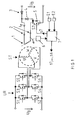
- FIG. 1 shows a circuit diagram of an exemplary embodiment for a device according to the invention.
- the figure 2 shows a diagram to explain the mode of operation the invention.
- FIG. 1 shows a circuit diagram of an exemplary embodiment for a device according to the invention. through the device shown is achieved in that Start-stop operation of the vehicle compared the start phase to known start-stop systems is shortened because the high torque required in the starting phase provided after a comparatively short time becomes.
- the device shown in FIG. 1 has an excitation winding 1 which is assigned to the starter generator of the vehicle.
- the excitation current I e flowing through the excitation winding 1 flows as a function of control signals s7, which are made available by a control unit 7.
- These control signals s7 are fed to a switch S7 implemented as a MOSFET, which then opens or closes.
- a diode 5 is arranged antiparallel to the switch S7 and a diode 4 is arranged antiparallel to the excitation winding 1.
- the control unit 7 is also provided with an input connection E1 connected, via which you get a sensor derived signal is supplied when the driver of the vehicle at the end of a stop phase in start-stop operation the accelerator pedal is pressed to start. Furthermore is the control unit 7 is connected to an input connection E2, over which you get one from another sensor derived signal is supplied when the vehicle by applying the brake to a standstill comes, for example at a traffic light stop.
- the control unit 7 is also provided with a sensor unit 6 connected by means of which the position of the winding axis the excitation winding 1 is detected.
- the control unit 7 generates control signals s1, ..., s7 in Dependence on the input signals fed to it Use of a stored in the control unit 7 Control program.
- the stator windings are controlled via a PWM converter UR, which has a total of six switches S1, ..., S6.
- the switches S1 and S2 are assigned to the phase winding U, the switches S3 and S4 to the phase winding V and the switches S5 and S6 to the phase winding W.
- the respective phase winding is connected to the connection point between the two switches assigned to it.
- a free-wheeling diode is arranged antiparallel to each switch S1, ..., S6.
- the converter is connected to the vehicle battery to which the vehicle electrical system voltage U B of 12V is applied.
- the switches S1, ..., S6 of the converter UR are used by the Control signals s1, ..., s6 controlled by the control unit 7 can be made available.
- the Sensor unit 6 the position of the winding axis of the excitation winding 1 detected.
- the information received about the Position of the winding axis of the excitation winding 1 is to the Control unit 7 passed on and buffered in this.
- the driver of the vehicle then actuates for the purpose of When the vehicle starts the accelerator pedal, this actuation of the accelerator pedal is detected by a sensor and reported to the control unit 7 via the input connection E1.
- the control unit 7 also generates a control signal s7 for the switch S7 in such a way that it switches through and releases a current flow through the excitation winding 1. This allows further field construction in the machine via the excitation circuit.
- FIG. 2 shows a diagram in which the time is plotted along the abscissa and the excitation current I e is plotted along the ordinate.
- the curve k1 illustrates the course of the excitation current I e when the excitation current is switched on in the conventional manner after the accelerator pedal of the vehicle has been actuated. It can be seen that the excitation current rises comparatively slowly and asymptotically approaches its final end value, which is approximately 19 A in the exemplary embodiment shown. For example, the excitation current is about 7A after 0.1s, about 12A after 0.2s, about 14A after 0.3s and about 16A after 0.4s.
- the curve k2 illustrates the course of the excitation current I e if, after actuation of the accelerator pedal of the vehicle, the above-described rapid excitation is first carried out using the stator-side converter UR, which is already present, and only then is the current flow through the excitation winding 1 released. It can be seen that in this case the excitation current jumps to a value of about 10 A after only about 10 ms and then approaches the stated stationary end value asymptotically.
- the curve k2 shows that the excitation current is already about 13A after 0.1s, about 15A after 0.2s, about 17A after 0.3s and about 18A after 0.4s.
- the claw-pole machine used as a belt-driven Starter generator of the vehicle when designing the winding is strongly saturated from an excitation current of about 12A is about 70 - 80% of the maximum torque available after about 70ms. In comparison a significant shortening to the state of the art the start time in the vehicle's start-stop mode.
- the invention achieves that the time required to set up the excitation field in comparison is reduced to known start-stop systems. This allows the required engine torque to quickly increase Be made available, which means the start time at a Start-stop system is reduced.
- the invention becomes the existing stator-side converter used the magnetic with a small time constant Build up energy for the excitation field in the machine. This is done using detection the position of the winding axis of the excitation winding in the Stop phase of the start-stop operation and one dependent on it Activation of the switches of the converter at the beginning the subsequent start phase.
- no additional capacitor is required in the excitation circuit, what the shake resistance of the claimed device favored.
- an additional diode is used, through which undesirable effects of the excitation winding induced high voltage avoided on electrical system consumers become.
- the algorithm for the described fast excitation can be easily started using simple state machines realize. Only a little is required Additional expenditure in the control electronics.
Landscapes
- Engineering & Computer Science (AREA)
- Chemical & Material Sciences (AREA)
- Combustion & Propulsion (AREA)
- Mechanical Engineering (AREA)
- General Engineering & Computer Science (AREA)
- Control Of Eletrric Generators (AREA)
Abstract
Description
Claims (5)
- Vorrichtung zur Verbesserung des Start-Stopp-Betriebes eines Fahrzeugs, welchedadurch gekennzeichnet, dasseine dem Startergenerator des Fahrzeugs zugeordnete und an das Bordnetz des Fahrzeugs angeschlossene Erregerwicklung,eine Steuereinheit, durch deren Steuersignale der durch die Erregerwicklung fließende Erregerstrom beeinflusst wird, undStatorwicklungen enthält, die über einen mehrere Schalter aufweisenden Umrichter mit dem Bordnetz des Fahrzeugs verbindbar sind,sie eine Sensoreinheit (6) aufweist, die in der Stopp-Phase des Start-Stopp-Betriebes die Lage der Wicklungsachse der Erregerwicklung (1) detektiert,die Sensoreinheit (6) mit der Steuereinheit (7) verbunden ist, unddie Steuereinheit (7) zur Einleitung eines Startvorganges Steuersignale (s1,...,s6) für die Schalter (S1,...,S6) des Umrichters (UR) derart generiert, dass in den Statorwicklungen (U,V,W) ein Stromfluss erzeugt wird, der ein in Richtung der Wicklungsachse der Erregerwicklung (1) gerichtetes Magnetfeld einstellt.
- Vorrichtung nach Anspruch 1, dadurch gekennzeichnet, dass die Steuereinheit (7) nach erfolgter Einstellung des in Richtung der Wicklungsachse der Erregerwicklung (1) gerichteten Magnetfelds Steuersignale (s1,...,s6) für die Schalter (S1,...,S6) des Umrichters (UR) derart generiert, dass der Stromfluss in den Statorwicklungen (U,V,W) endet, und einen Erregerstromfluss bewirkende Steuersignale (s7) generiert.
- Vorrichtung nach Anspruch 1 oder 2, dadurch gekennzeichnet, dass die Steuereinheit (7) die den Stromfluss in den Statorwicklungen (U,V,W) bewirkenden Steuersignale (s1,...,s6) nach einer Betätigung des Gaspedals des Fahrzeugs generiert.
- Vorrichtung nach Anspruch 2 oder 3, dadurch gekennzeichnet, dass die Steuereinheit (7) die den Stromfluss in den Statorwicklungen (U,V,W) beendenden Steuersignale (s1,...,s6) und die den Erregerstromfluss bewirkenden Steuersignale (s7) nach Ablauf eines vorgegebenen Zeitintervalles nach der Einleitung eines Startvorgangs generiert.
- Vorrichtung nach einem der vorhergehenden Ansprüche, dadurch gekennzeichnet , dass zwischen der Erregerwicklung (1) und dem Bordnetz eine Diode (3) angeordnet ist, deren Kathode mit der Erregerwicklung (1) und deren Anode mit dem Bordnetz verbunden ist.
Applications Claiming Priority (2)
| Application Number | Priority Date | Filing Date | Title |
|---|---|---|---|
| DE10317092A DE10317092A1 (de) | 2003-04-14 | 2003-04-14 | Vorrichtung zur Verbesserung des Start-Stopp-Betriebes eines Fahrzeugs |
| DE10317092 | 2003-04-14 |
Publications (2)
| Publication Number | Publication Date |
|---|---|
| EP1469588A1 true EP1469588A1 (de) | 2004-10-20 |
| EP1469588B1 EP1469588B1 (de) | 2005-12-28 |
Family
ID=32892336
Family Applications (1)
| Application Number | Title | Priority Date | Filing Date |
|---|---|---|---|
| EP04002285A Expired - Lifetime EP1469588B1 (de) | 2003-04-14 | 2004-02-03 | Vorrichtung zur Verbesserung des Start-Stopp-Betriebes eines Fahrzeugs |
Country Status (3)
| Country | Link |
|---|---|
| EP (1) | EP1469588B1 (de) |
| DE (2) | DE10317092A1 (de) |
| ES (1) | ES2254998T3 (de) |
Families Citing this family (1)
| Publication number | Priority date | Publication date | Assignee | Title |
|---|---|---|---|---|
| DE102013204200A1 (de) | 2013-03-12 | 2014-09-18 | Robert Bosch Gmbh | Elektrische Maschine in einem Kraftfahrzeug mit Drehzahlsignaleingang |
Citations (3)
| Publication number | Priority date | Publication date | Assignee | Title |
|---|---|---|---|---|
| US4630577A (en) * | 1984-03-26 | 1986-12-23 | Fiat Auto S.P.A. | Stop-start device for controlling the operation of an internal combustion engine of a vehicle provided with an automatic transmission |
| FR2729435A1 (fr) * | 1995-01-16 | 1996-07-19 | Kovacs Andre Louis | Demarreur electrique de moteur thermique integrant un redemarreur inertiel de substitution |
| US6313601B1 (en) * | 1999-06-14 | 2001-11-06 | Teac Corporation | Speed control of a motor |
-
2003
- 2003-04-14 DE DE10317092A patent/DE10317092A1/de not_active Withdrawn
-
2004
- 2004-02-03 DE DE502004000219T patent/DE502004000219D1/de not_active Expired - Lifetime
- 2004-02-03 ES ES04002285T patent/ES2254998T3/es not_active Expired - Lifetime
- 2004-02-03 EP EP04002285A patent/EP1469588B1/de not_active Expired - Lifetime
Patent Citations (3)
| Publication number | Priority date | Publication date | Assignee | Title |
|---|---|---|---|---|
| US4630577A (en) * | 1984-03-26 | 1986-12-23 | Fiat Auto S.P.A. | Stop-start device for controlling the operation of an internal combustion engine of a vehicle provided with an automatic transmission |
| FR2729435A1 (fr) * | 1995-01-16 | 1996-07-19 | Kovacs Andre Louis | Demarreur electrique de moteur thermique integrant un redemarreur inertiel de substitution |
| US6313601B1 (en) * | 1999-06-14 | 2001-11-06 | Teac Corporation | Speed control of a motor |
Also Published As
| Publication number | Publication date |
|---|---|
| EP1469588B1 (de) | 2005-12-28 |
| DE10317092A1 (de) | 2004-11-11 |
| ES2254998T3 (es) | 2006-06-16 |
| DE502004000219D1 (de) | 2006-02-02 |
Similar Documents
| Publication | Publication Date | Title |
|---|---|---|
| DE69733866T2 (de) | Regler für den Antrieb eines Permanentmagnet-Synchronmotors | |
| DE69713641T2 (de) | Alternator für Kraftfahrzeug angewendet als Generator und als elektrischer Motor zum Anlassen des Verbrennungsmotors des Kraftfahrzeuges | |
| DE69402802T2 (de) | Steuer-verfahren für elektrische Geräte in Hybridfahrzeugen | |
| EP2823178B1 (de) | Verfahren zum vorbereiten des startens eines verbrennungsmotors durch einen riemengetriebenen startergenerator | |
| DE102011007874A1 (de) | Vorrichtung und Verfahren zum Starten eines in einem Fahrzeug angeordneten Verbrennungsmotors | |
| DE112015003212T5 (de) | Elektrische Servolenkvorrichtung und elektrisches Servolenksystem | |
| DE102019124214A1 (de) | Verfahren zum Betrieb eines Kraftfahrzeugs mit einer permanenterregten Synchronmaschine und Kraftfahrzeug | |
| DE10392456T5 (de) | Anordnung für die Durchführung eines Verfahrens zur Steuerung einer mehrphasigen und reversiblen rotierenden elektrischen Maschine, die mit einem Verbrennungsmotor eines Kraftfahrzeugs verbunden ist | |
| DE102021129144B4 (de) | Verfahren zum Betreiben einer elektrischen Schaltungsanordnung, elektrische Schaltung und Kraftfahrzeug | |
| DE69905239T2 (de) | Steuervorrichtung für anlasser eines kraftfahrzeuges | |
| DE19518991A1 (de) | Verfahren zum Betrieb eines elektronisch kommutierten Motors, und Motor zur Durchführung eines solchen Verfahrens | |
| EP1469587B1 (de) | Vorrichtung zur Verbesserung des Start-Stopp-Betriebes eines Fahrzeugs | |
| EP3092706A1 (de) | Verfahren zum betreiben eines aktiven gleichrichters, schaltungsanordnung und computerprogramm | |
| DE102005012093B4 (de) | Motorsteuervorrichtung | |
| DE112014000754T5 (de) | Starter- und Schaltsystem mit variablem Fluss | |
| EP1469588B1 (de) | Vorrichtung zur Verbesserung des Start-Stopp-Betriebes eines Fahrzeugs | |
| EP1469586B1 (de) | Vorrichtung zur Verbesserung des Start-Stopp-Betriebes eines Fahrzeuges | |
| WO2019174804A1 (de) | Verfahren zum erkennen eines fehlerzustands einer elektrischen maschine | |
| WO2012107330A2 (de) | Verfahren zum regeln eines von einer elektrischen maschine in einem kraftfahrzeug abgegebenen ist-drehmoments auf ein soll-drehmoment | |
| WO2003094336A1 (de) | Schaltungsanordnung zur versorgung der steuerelektronik bei elektrischen maschinen | |
| DE102020000822B4 (de) | Motorantriebseinrichtung | |
| DE10317093A1 (de) | Vorrichtung zur Verbesserung des Start-Stopp-Betriebes eines Fahrzeugs | |
| EP1289120A1 (de) | Verfahren zur impulsartigen Erhöhung des Drehmomentes eines Asynchronmotors | |
| DE102011087523A1 (de) | Verfahren zum Betreiben einer fremderregten elektrischen Maschine in einem Kraftfahrzeug | |
| DE102010041976B4 (de) | Verfahren zum Betreiben einer Brennkraftmaschine, elektrische Maschine einer Brennkraftmaschine und Motorsteuergerät zum Steuern und/oder Regeln einer Brennkraftmaschine |
Legal Events
| Date | Code | Title | Description |
|---|---|---|---|
| PUAI | Public reference made under article 153(3) epc to a published international application that has entered the european phase |
Free format text: ORIGINAL CODE: 0009012 |
|
| AK | Designated contracting states |
Kind code of ref document: A1 Designated state(s): AT BE BG CH CY CZ DE DK EE ES FI FR GB GR HU IE IT LI LU MC NL PT RO SE SI SK TR |
|
| AX | Request for extension of the european patent |
Extension state: AL LT LV MK |
|
| GRAP | Despatch of communication of intention to grant a patent |
Free format text: ORIGINAL CODE: EPIDOSNIGR1 |
|
| 17P | Request for examination filed |
Effective date: 20050420 |
|
| AKX | Designation fees paid |
Designated state(s): DE ES FR GB IT |
|
| GRAS | Grant fee paid |
Free format text: ORIGINAL CODE: EPIDOSNIGR3 |
|
| GRAA | (expected) grant |
Free format text: ORIGINAL CODE: 0009210 |
|
| AK | Designated contracting states |
Kind code of ref document: B1 Designated state(s): DE ES FR GB IT |
|
| REG | Reference to a national code |
Ref country code: GB Ref legal event code: FG4D Free format text: NOT ENGLISH |
|
| REF | Corresponds to: |
Ref document number: 502004000219 Country of ref document: DE Date of ref document: 20060202 Kind code of ref document: P |
|
| GBT | Gb: translation of ep patent filed (gb section 77(6)(a)/1977) |
Effective date: 20060406 |
|
| REG | Reference to a national code |
Ref country code: ES Ref legal event code: FG2A Ref document number: 2254998 Country of ref document: ES Kind code of ref document: T3 |
|
| ET | Fr: translation filed | ||
| PLBE | No opposition filed within time limit |
Free format text: ORIGINAL CODE: 0009261 |
|
| STAA | Information on the status of an ep patent application or granted ep patent |
Free format text: STATUS: NO OPPOSITION FILED WITHIN TIME LIMIT |
|
| 26N | No opposition filed |
Effective date: 20060929 |
|
| PGFP | Annual fee paid to national office [announced via postgrant information from national office to epo] |
Ref country code: ES Payment date: 20100219 Year of fee payment: 7 |
|
| PGFP | Annual fee paid to national office [announced via postgrant information from national office to epo] |
Ref country code: GB Payment date: 20100219 Year of fee payment: 7 |
|
| GBPC | Gb: european patent ceased through non-payment of renewal fee |
Effective date: 20110203 |
|
| PG25 | Lapsed in a contracting state [announced via postgrant information from national office to epo] |
Ref country code: GB Free format text: LAPSE BECAUSE OF NON-PAYMENT OF DUE FEES Effective date: 20110203 |
|
| REG | Reference to a national code |
Ref country code: ES Ref legal event code: FD2A Effective date: 20120411 |
|
| PG25 | Lapsed in a contracting state [announced via postgrant information from national office to epo] |
Ref country code: ES Free format text: LAPSE BECAUSE OF NON-PAYMENT OF DUE FEES Effective date: 20110204 |
|
| PGFP | Annual fee paid to national office [announced via postgrant information from national office to epo] |
Ref country code: DE Payment date: 20140417 Year of fee payment: 11 |
|
| REG | Reference to a national code |
Ref country code: FR Ref legal event code: PLFP Year of fee payment: 12 |
|
| PGFP | Annual fee paid to national office [announced via postgrant information from national office to epo] |
Ref country code: IT Payment date: 20150223 Year of fee payment: 12 |
|
| PGFP | Annual fee paid to national office [announced via postgrant information from national office to epo] |
Ref country code: FR Payment date: 20150217 Year of fee payment: 12 |
|
| REG | Reference to a national code |
Ref country code: DE Ref legal event code: R119 Ref document number: 502004000219 Country of ref document: DE |
|
| PG25 | Lapsed in a contracting state [announced via postgrant information from national office to epo] |
Ref country code: DE Free format text: LAPSE BECAUSE OF NON-PAYMENT OF DUE FEES Effective date: 20150901 |
|
| REG | Reference to a national code |
Ref country code: FR Ref legal event code: ST Effective date: 20161028 |
|
| PG25 | Lapsed in a contracting state [announced via postgrant information from national office to epo] |
Ref country code: IT Free format text: LAPSE BECAUSE OF NON-PAYMENT OF DUE FEES Effective date: 20160203 |
|
| PG25 | Lapsed in a contracting state [announced via postgrant information from national office to epo] |
Ref country code: FR Free format text: LAPSE BECAUSE OF NON-PAYMENT OF DUE FEES Effective date: 20160229 |