EP1469452A2 - Bildanzeigevorrichtung in einem Spielautomat - Google Patents
Bildanzeigevorrichtung in einem Spielautomat Download PDFInfo
- Publication number
- EP1469452A2 EP1469452A2 EP04004714A EP04004714A EP1469452A2 EP 1469452 A2 EP1469452 A2 EP 1469452A2 EP 04004714 A EP04004714 A EP 04004714A EP 04004714 A EP04004714 A EP 04004714A EP 1469452 A2 EP1469452 A2 EP 1469452A2
- Authority
- EP
- European Patent Office
- Prior art keywords
- pixel
- pixel electrodes
- information signal
- pair
- gaming machine
- Prior art date
- Legal status (The legal status is an assumption and is not a legal conclusion. Google has not performed a legal analysis and makes no representation as to the accuracy of the status listed.)
- Withdrawn
Links
- 239000004973 liquid crystal related substance Substances 0.000 claims description 26
- 239000003086 colorant Substances 0.000 claims description 8
- 239000011159 matrix material Substances 0.000 claims description 8
- 238000013461 design Methods 0.000 description 16
- 238000010586 diagram Methods 0.000 description 8
- 230000006872 improvement Effects 0.000 description 5
- 238000012545 processing Methods 0.000 description 4
- 230000035945 sensitivity Effects 0.000 description 4
- 230000007480 spreading Effects 0.000 description 4
- 230000000694 effects Effects 0.000 description 3
- 230000006870 function Effects 0.000 description 3
- 238000005070 sampling Methods 0.000 description 3
- 239000010409 thin film Substances 0.000 description 3
- 230000009471 action Effects 0.000 description 2
- 238000013459 approach Methods 0.000 description 2
- 238000012937 correction Methods 0.000 description 2
- 238000004519 manufacturing process Methods 0.000 description 2
- 238000012986 modification Methods 0.000 description 2
- 230000004048 modification Effects 0.000 description 2
- 239000000758 substrate Substances 0.000 description 2
- ATJFFYVFTNAWJD-UHFFFAOYSA-N Tin Chemical compound [Sn] ATJFFYVFTNAWJD-UHFFFAOYSA-N 0.000 description 1
- 230000003044 adaptive effect Effects 0.000 description 1
- 230000005540 biological transmission Effects 0.000 description 1
- 230000008859 change Effects 0.000 description 1
- 230000007274 generation of a signal involved in cell-cell signaling Effects 0.000 description 1
- 229910052738 indium Inorganic materials 0.000 description 1
- APFVFJFRJDLVQX-UHFFFAOYSA-N indium atom Chemical compound [In] APFVFJFRJDLVQX-UHFFFAOYSA-N 0.000 description 1
- 238000003780 insertion Methods 0.000 description 1
- 230000037431 insertion Effects 0.000 description 1
- 230000002093 peripheral effect Effects 0.000 description 1
- 230000004044 response Effects 0.000 description 1
- 239000000126 substance Substances 0.000 description 1
Images



Classifications
-
- G—PHYSICS
- G07—CHECKING-DEVICES
- G07F—COIN-FREED OR LIKE APPARATUS
- G07F17/00—Coin-freed apparatus for hiring articles; Coin-freed facilities or services
- G07F17/32—Coin-freed apparatus for hiring articles; Coin-freed facilities or services for games, toys, sports, or amusements
- G07F17/3202—Hardware aspects of a gaming system, e.g. components, construction, architecture thereof
-
- G—PHYSICS
- G07—CHECKING-DEVICES
- G07F—COIN-FREED OR LIKE APPARATUS
- G07F17/00—Coin-freed apparatus for hiring articles; Coin-freed facilities or services
- G07F17/32—Coin-freed apparatus for hiring articles; Coin-freed facilities or services for games, toys, sports, or amusements
- G07F17/3202—Hardware aspects of a gaming system, e.g. components, construction, architecture thereof
- G07F17/3204—Player-machine interfaces
- G07F17/3211—Display means
-
- G—PHYSICS
- G09—EDUCATION; CRYPTOGRAPHY; DISPLAY; ADVERTISING; SEALS
- G09G—ARRANGEMENTS OR CIRCUITS FOR CONTROL OF INDICATING DEVICES USING STATIC MEANS TO PRESENT VARIABLE INFORMATION
- G09G3/00—Control arrangements or circuits, of interest only in connection with visual indicators other than cathode-ray tubes
- G09G3/20—Control arrangements or circuits, of interest only in connection with visual indicators other than cathode-ray tubes for presentation of an assembly of a number of characters, e.g. a page, by composing the assembly by combination of individual elements arranged in a matrix no fixed position being assigned to or needed to be assigned to the individual characters or partial characters
- G09G3/34—Control arrangements or circuits, of interest only in connection with visual indicators other than cathode-ray tubes for presentation of an assembly of a number of characters, e.g. a page, by composing the assembly by combination of individual elements arranged in a matrix no fixed position being assigned to or needed to be assigned to the individual characters or partial characters by control of light from an independent source
- G09G3/36—Control arrangements or circuits, of interest only in connection with visual indicators other than cathode-ray tubes for presentation of an assembly of a number of characters, e.g. a page, by composing the assembly by combination of individual elements arranged in a matrix no fixed position being assigned to or needed to be assigned to the individual characters or partial characters by control of light from an independent source using liquid crystals
- G09G3/3607—Control arrangements or circuits, of interest only in connection with visual indicators other than cathode-ray tubes for presentation of an assembly of a number of characters, e.g. a page, by composing the assembly by combination of individual elements arranged in a matrix no fixed position being assigned to or needed to be assigned to the individual characters or partial characters by control of light from an independent source using liquid crystals for displaying colours or for displaying grey scales with a specific pixel layout, e.g. using sub-pixels
-
- G—PHYSICS
- G09—EDUCATION; CRYPTOGRAPHY; DISPLAY; ADVERTISING; SEALS
- G09G—ARRANGEMENTS OR CIRCUITS FOR CONTROL OF INDICATING DEVICES USING STATIC MEANS TO PRESENT VARIABLE INFORMATION
- G09G2300/00—Aspects of the constitution of display devices
- G09G2300/04—Structural and physical details of display devices
- G09G2300/0439—Pixel structures
- G09G2300/0452—Details of colour pixel setup, e.g. pixel composed of a red, a blue and two green components
-
- G—PHYSICS
- G09—EDUCATION; CRYPTOGRAPHY; DISPLAY; ADVERTISING; SEALS
- G09G—ARRANGEMENTS OR CIRCUITS FOR CONTROL OF INDICATING DEVICES USING STATIC MEANS TO PRESENT VARIABLE INFORMATION
- G09G3/00—Control arrangements or circuits, of interest only in connection with visual indicators other than cathode-ray tubes
- G09G3/20—Control arrangements or circuits, of interest only in connection with visual indicators other than cathode-ray tubes for presentation of an assembly of a number of characters, e.g. a page, by composing the assembly by combination of individual elements arranged in a matrix no fixed position being assigned to or needed to be assigned to the individual characters or partial characters
- G09G3/34—Control arrangements or circuits, of interest only in connection with visual indicators other than cathode-ray tubes for presentation of an assembly of a number of characters, e.g. a page, by composing the assembly by combination of individual elements arranged in a matrix no fixed position being assigned to or needed to be assigned to the individual characters or partial characters by control of light from an independent source
- G09G3/36—Control arrangements or circuits, of interest only in connection with visual indicators other than cathode-ray tubes for presentation of an assembly of a number of characters, e.g. a page, by composing the assembly by combination of individual elements arranged in a matrix no fixed position being assigned to or needed to be assigned to the individual characters or partial characters by control of light from an independent source using liquid crystals
- G09G3/3611—Control of matrices with row and column drivers
- G09G3/3648—Control of matrices with row and column drivers using an active matrix
Definitions
- This invention relates to a display device which is provided in a gaming machine such as a slot machine or a pachinko machine.
- this invention is made in view of the above problems, and provides a display device and a gaming machine which can make pixels of the display device fine and can achieve improvement in image quality without increasing image data in the display device, with which the gaming machine such as a slot machine or a pachinko machine is equipped.
- this invention is a display device provided in a gaming machine such as a slot machine or a pachinko machine, comprising pixel units each of which is constituted by arranging each one of a plurality of kinds of pixel electrodes that display predetermined colors respectively, wherein one pixel is constituted by a pair of adjacent pixel units, and an information signal for the pixel is supplied in the substantially same timing to pixel electrodes for the same color included in the pair of the pixel units, respectively.
- the image display device may further comprise drive control means for controlling the information signal supplied to the pixel electrodes, wherein the drive control means supplies the information signal in the substantially same timing to pixel electrodes for the same color included in the pair of the pixel units, respectively.
- the image display device may further comprise: drive control means for controlling the information signal supplied to the pixel electrodes; and information signal lines that connect outputs for one pixel from the drive control means with the pixel electrodes for the same color included in the pair of the pixel units respectively in a one-to-many relationship.
- an information signal for one pixel is supplied through the information signal lines that connect pixel electrodes for the same color included in a pair of adjacent pixel units with outputs of the drive control means in a one-to-many relationship.
- a pitch P between pixel units and a distance d to a player in a normal game posture from the display device concerned satisfying a relationship of P ⁇ tan ( ⁇ /180/35) ⁇ d pixel lines can be made hardly conspicuous. According to this invention, it is possible to attain finer pixels by adopting the above-mentioned constitution and to easily achieve the pitch P between pixel units satisfying the above-mentioned relationship.
- pixel electrodes are arranged in matrix on an xy plane, and that pixel electrodes for the same color are arranged in a y direction and the same pattern is continuously arranged in an x direction to form a stripe.
- pixel electrodes of the same color are lined in the y direction, it is possible to reduce the spreading of an image at the time of displaying a slant line in comparison with the pixel electrodes arranged in other forms, such as a delta arrangement, a mosaic arrangement, or the like. Hence, it becomes possible to improve the image quality.
- this invention may include a gaming machine, such as a slot machine or a pachinko machine.
- the gaming machine comprises a display unit that is constituted by a plurality of kinds of pixel electrodes that display predetermined colors respectively and are arranged in matrix, wherein the display unit has pixel units each of which is constituted by arranging each one of a plurality of kinds of pixel electrodes that display predetermined colors respectively, one pixel is constituted by a pair of adjacent pixel units, and an information signal for the pixel is supplied in the substantially same timing to pixel electrodes for the same color included in the pair of the pixel units, respectively.
- the display unit provided in the gaming machine by displaying data for one pixel of existing image data with a pair of pixel electrodes, it becomes possible to make the pitch between pixel units about one half of the conventional one without increasing a data amount of the existing image data. Hence, it becomes possible to achieve finer pixels, and consequently, it becomes possible to display effectively the image according to the progress of the game in the gaming machine.
- the gaming machine may further comprises drive control means for controlling the information signal supplied to the pixel electrodes, wherein the drive control means supplies the information signal in the substantially same timing to pixel electrodes for the same color included in the pair of the pixel units, respectively.
- the gaming machine may further comprise: drive control means for controlling the information signal supplied to the pixel electrodes; and information signal lines that connect outputs for one pixel from the drive control means with the pixel electrodes for the same color included in the pair of the pixel units respectively in a one-to-many relationship.
- an information signal for one pixel is supplied through the information signal lines that connect pixel electrodes for the same color included in a pair of adjacent pixel units with outputs of the drive control means in a one-to-many relationship.
- pixel electrodes are arranged in matrix on an xy plane, and that pixel electrodes for the same color are arranged in a y direction and the same pattern is continuously arranged in an x direction to form a stripe.
- pixel electrodes of the same color are lined in the y direction, it is possible to reduce the spreading of an image at the time of displaying a slant line in comparison with the pixel electrodes arranged in other forms. Hence, it becomes possible to improve the image quality.
- the display unit is a highly transmissive liquid crystal display provided on a game board.
- the display board such as a reel unit of a slot machine, or a game board of a pachinko machine, with being overlapped.
- the display board such as a reel unit of a slot machine, or a game board of a pachinko machine, with being overlapped.
- Fig. 2 is an explanatory diagram schematically showing a display screen of a display device according to a first embodiment. Note that, in this figure, only 4 pixels in 2 x 2 are shown in an enlarged manner.
- a plurality of kinds of pixel electrodes R, G, and B (hereinafter, these are called Ra, Ga, Ba, Rb, Gb, and Bb appropriately) that display three colors of R (red), G (green), and B (blue) respectively are arranged in matrix on an xy plane, and pixel electrodes for the same color are arranged in the y direction and the same pattern is continuously arranged in the x direction to form a stripe.
- pixel units a and b are formed by arranging each kind of pixel electrodes R, G, and B, and one pixel is constituted by one pair of adjacent pixel units.
- a pixel unit a is formed by adjacently arranging the pixel electrodes Ra, Ga, and Ba
- a pixel unit b is formed by adjacently arranging the pixel electrodes Rb, Gb, and Bb, and one pixel data is displayed by these adjacent pixel units a and b.
- Fig. 3 shows a concrete configuration of this display screen.
- gate lines G1, G2,... that are wired in a horizontal direction in this figure (corresponding to the x direction in Fig. 2) and are connected to the scanning signal driver 11
- information signal lines (source lines) DRa, DGa,... that are wired in a vertical direction in this figure (corresponding to the y direction in Fig. 2) and are connected to the information signal driver 10 that is drive control means are provided on a liquid crystal panel substrate so that they may be orthogonal in the condition of being insulated mutually.
- TFT thin film transistor
- the gate lines G1, G2,... are connected to gate electrodes of the TFTs
- the information signal lines DRa, DGa,... are connected to source electrodes of the TFTs
- the pixel electrodes are connected to drain electrodes of the TFTs.
- outputs for one pixel from the information signal driver 10 which is drive control means, and respective pixel electrodes Ra, Ga, Ba, Rb, Gb, and Bb included in the pair of pixel units a and b are connected in a one-to-many relationship. That is, each of the information signal lines DRa, DGa, DBa, DRb, DGb, DBb... is branched on the way, and outputs for one pixel from the information signal driver 10, and pixel electrodes for the same color included in a pair of pixel units a and b respectively are connected in a one-to-two relationship.
- one pixel is constituted by one pair of adjacent pixel units a and b, and the information signal line DR is connected to the pixel electrodes Ra and Rb, the information signal line DG is to the pixel electrodes Ga and Gb, and the information signal line DB is to the pixel electrodes Ba and Bb.
- the scanning signal driver 11 makes the scanning selection of the gate lines G1, G2,... by turns to supply gate voltages.
- the information signal driver 10 supplies information signal voltages, corresponding to respective pixel data, to the information signal lines DRa, DGa,..., and applies them to respective pixel electrodes through the TFTs.
- Fig. 4 shows the application timing of these information signal voltages.
- this figure shows voltage levels in a positive field and a negative field that are applied to the gate lines and information signal lines in the case that one frame is scanned by shuttling.
- the information signal voltages for one pixel are supplied in the same timing to pixel electrodes for the same color included in a pair of pixel units a and b.
- the scanning selection of the gate lines G1, G2,... is made by turns, the voltages are applied, and in synchronization with this timing of application to respective gate lines, information signal voltages at the same level and in the same timing are applied through the information signal lines DRa, DGa,... to pairs of pixel electrodes (Ra, Rb), (Ga, Gb), and (Ba, Bb).
- this invention is not limited to this. As shown in Fig. 5, this invention is applicable also to a mosaic arrangement (Fig. 5(a)), a delta arrangement (Fig. 5(b)), or a 2G square arrangement (Fig. 5(c)). Also, in these cases, information signals for one pixel are supplied at the same level and in the same timing to respective pixel electrodes for the same color included in the pair of pixel units a and b.
- FIG. 6 is a perspective view and a front view that show the slot machine 1 according to this embodiment.
- a game board 2 is provided in the front of a main body of the slot machine 1, and on this game board 2, a transparent liquid crystal display 3 which is the display device mentioned above is provided in an area shown by dotted lines in the figure.
- reel display windows 3a are formed in this transparent liquid crystal display 3.
- various display units, such as lamps and segment indicators, are provided also in areas other than the transparent liquid crystal display 3 on the game board 2.
- the slot machine 1 comprises a speaker 4, a lamp 5, an operation switch unit 6, and a medal receiving tray 1a in the front of the main body.
- the transparent liquid crystal display 3 is a highly transmissive liquid crystal display, and electrodes which apply voltages to liquid crystal are formed with electroconductive substances (for example, adaptive oxide of indium and tin, etc.) in transparent thin films.
- Fig. 7 is a block diagram showing the configuration of a control unit 7 provided inside the slot machine 1.
- the slot machine 1 comprises a main control circuit 71 for controlling game processing operation in the slot machine 1, peripheral devices (actuator etc.) electrically connected to the main control circuit 71, and a sub-control circuit 72 for controlling the transparent liquid crystal display 3 and speaker 4 on the basis of a control instruction transmitted from the main control circuit 71.
- the main control circuit 71 mainly comprises a CPU arranged on a circuit board, and in addition to this, comprises a circuit performing random sampling at the time of performing the probability lottery processing of determining a winning.
- the CPU serves as internal winning combination determination means and winning judgment means to perform control operation according to a program set up beforehand, and also comprises ROM and RAM served as memory means.
- This memory means (ROM and RAM) stores the data used for the judgment of random sampling performed every start operation, and various control instructions (commands) for transmission to the sub-control circuit 72.
- main actuators As the main actuators whose operation is controlled by control signals from the above-mentioned main control circuit 71, there are a lamp 5, various display units on the game board 2, a hopper (including a drive unit for payout) that contains coins and pays out the predetermined number of coins to the medal receiving tray 1a, which are shown in Fig. 6, and stepping motors for rotating reels.
- Each of these actuators is connected to an output unit of the above-mentioned main control circuit 71 through a drive circuit provided for each, and its operation is controlled in response to a control signal, such as a drive instruction outputted from the CPU.
- main input signal generation means generating an input signal required for the main control circuit 71 to generate a control command
- the operation switch unit 6 provided in the front of the slot machine 1, and an inserted coin sensor, and various sensors detecting operating statuses of reels are provided.
- the operation switch unit 6 detects the start of a game, and a stop operation of each reel, and the inserted coin sensor detects a coin inserted into a coin insertion slot.
- the various sensors for each reel supply signals for identifying respective reel positions to the main control circuit 71.
- a design table is stored in ROM.
- each code number given one by one for every fixed rotation pitch of each reel is associated with each design code showing a kind of a design provided correspondingly for the code number.
- a winning design combination table is also stored in the ROM. On this winning design combination table, combinations of the designs showing winnings, coin payoff amounts of winnings, and winning judgment code showing those winnings are associated with each other. The above-described winning design combination table will be referred to when performing winning identification at the time of the stop of all reels.
- the sub-control circuit 72 performs the display control of the transparent liquid crystal display 3, and the output control of sound from the speaker 4 on the basis of control instructions (commands) from the main control circuit 71.
- This sub-control circuit 72 is configured on a circuit board other than the circuit board where the main control circuit 71 is configured.
- This mainly comprises a microcomputer (hereafter, this is called "sub-microcomputer") 73, and is constituted by an image control circuit 81 as display control means for the transparent liquid crystal display 3, a sound source IC 78 controlling the sound outputted by the speaker 4, and a power amplifier 79 as an amplifier.
- the above-mentioned sub-microcomputer 73 includes a sub-CPU 74 performing control operation according to a control instruction transmitted from the main control circuit 71, a program ROM 75 as memory means, and a work RAM 76.
- the sub-control circuit 72 is configured so as to execute random sampling on an operating program in the sub-CPU 74.
- the program ROM 75 stores a control program executed by the sub-CPU 74.
- the work RAM 76 functions as temporary storage means when the sub-CPU 74 executes the above-mentioned control program.
- the image control circuit 81 is constituted by an image control CPU 82, an image control work RAM 83, an image control program ROM 84, an image ROM 86, a video RAM 87, and an image control IC 88.
- the image control CPU 82 determines the contents of display in the transparent liquid crystal display 3 according to the image control program stored in the image control program ROM 84 on the basis of parameters set up by the sub-microcomputer 73.
- the image control program ROM 84 stores the image control program and various selection tables that relate to the display in the transparent liquid crystal display 3.
- the image control work RAM 83 functions as temporary storage means when the image control CPU 82 executes the above-mentioned image control program.
- the image control IC 88 forms an image according to the contents of display determined by the image control CPU 82, and outputs it to the transparent liquid crystal display 3.
- the image ROM 86 stores dot data for forming an image.
- the video RAM 87 functions as temporary storage means when the image control IC 88 forms an image.
- the operation switch unit 6 detects a player's operation. According to an operation signal from the operation switch unit 6, the control unit 7 drives each actuator to start a game. Subsequently, according to the stop operation of a player, each reel is stopped by turns. Then, when all reels stop, the main control circuit 71 refers to the winning design combination table in ROM to judge whether there is any winning design combination among combinations of designs currently displayed on the reel display window 3a. When there is a design combination which is a winning, the main control circuit 71 pays off the payoff amount of medals corresponding to the winning to the medal saucer 1a out of a hopper. Moreover, the main control circuit 71 outputs suitably to the sub-control circuit 72 a control instruction according to internal winning combination obtained as a result of the probability lottery processing, a player's stop operation, a kind of the winning, and the like.
- the sub-control circuit 72 performs the display control of the transparent liquid crystal display 3, and the output control for sound from the speaker 4 on the basis of control instructions (commands) from the main control circuit 71. That is, the image control CPU 82 of the image control circuit 81 determines the contents of display in the transparent liquid crystal display 3 according to the image control program stored in the image control program ROM 84 on the basis of parameters set up by the sub-microcomputer 73. The image control IC 88 forms image data according to the contents of display determined by the image control CPU 82, and outputs it to the transparent liquid crystal display 3.
- the scanning signal driver 11 makes scanning selection of the gate lines G1, G2,... by turns to supply gate voltages.
- the information signal driver 10 applies information signal voltages for one pixel to each of pixel electrodes Ra, Ga, Ba, Rb, Gb, and Bb for the same color, which are included in each of a pair of pixel units, at the same level of the information signal voltages. Consequently, the image is displayed on the game board 2 so as to overlap with designs of each reel visually recognized through the reel display windows 3a.
- the information signals for one pixel are supplied to each of the pixel electrodes Ra, Ga, Ba, Rb, Gb, and Bb for the same color included in the adjacent pixel units a and b respectively.
- the display device 3 and slot machine 1 in accordance with this embodiment by displaying one pixel of the existing image data by pairs of pixel electrodes (Ra, Rb), (Ga, Gb), and (Ba, Bb), as shown in Fig. 2, it becomes possible to make the pitch P between pixel units about one half of the conventional one without increasing the data amount of existing image data. Hence, finer pixels can be attained.
- the pixel electrodes Ra, Ga, Ba, Rb, Gb, and Bb are arranged in a stripe on the xy plane. It is therefore possible to reduce the spreading of an image at the time of displaying a slant line in comparison with the case where pixel electrodes are arranged in other forms, such as a delta arrangement, a mosaic arrangement, or the like. Hence, it becomes possible to improve the image quality.
- a display device is made to be the highly transmissive transparent liquid crystal display 3 pasted to the game plane 2. Hence, it becomes possible to display images overlapping with designs of reels, being visible through the real display windows 3a and provided inside the main body, and with the game board 2. Hence, it is possible to attain improvement in power of expression more effectively.
- an output for one pixel from the information signal driver 10 which is drive control means, and respective pixel electrodes Ra, Ga, Ba, Rb, Gb, and Bb included in a pair of the above-mentioned pixel units a and b are connected in a one-to-many relationship.
- a plurality of kinds of pixel electrodes R, G, and B that display three colors of R (red), G (green), and B (blue) respectively are arranged in matrix on an xy plane, and pixel electrodes of the same color are arranged in the y direction and the same pattern is continuously arranged in the x direction to form a stripe (see Fig.2).
- pixel units a and b are formed by arranging each kind of pixel electrodes R, G, and B, and one pixel is constituted by one pair of adjacent pixel units.
- the pixel unit a is formed by adjacently arranging the pixel electrodes Ra, Ga, and Ba
- the pixel unit b is formed by adjacently arranging the pixel electrodes Rb, Gb, and Bb, and one pixel data is displayed by these adjacent pixel units a and b.
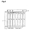
- Fig. 8 shows a concrete configuration of this display screen.
- gate lines G1, G2,... that are wired in the horizontal direction in this figure and are connected to the scanning signal driver 11
- information signal lines (source lines) DR, DG, DB,... that are wired in the vertical direction in this figure and are connected to the information signal driver 10 that is drive control means are provided on a liquid crystal panel substrate so that they may be orthogonal in the condition of being insulated mutually.
- TFT thin film transistor
- Each of the information signal lines DR, DG, DB,... is branched on the way, and outputs for one pixel from the information signal driver 10, and pixel electrodes for the same color included in a pair of pixel units a and b respectively are connected in a one-to-two relationship. That is, the information signal line DR is connected to the pixel electrodes Ra and Rb, the information signal line DG is to the pixel electrodes Ga and Gb, and the information signal line DB is to the pixel electrodes Ba and Bb.
- the scanning signal driver 11 makes the scanning selection of the gate lines G1, G2,... by turns to supply gate voltages.
- the information signal driver 10 supplies information signal voltages, corresponding to respective pixel data, to the information signal lines DR, DG, DB,..., and applies them to respective pixel electrodes through the TFTs.
- outputs for one pixel from the information signal driver 10, and pixel electrodes for the same color included in the pixel units a and b respectively are connected in the one-to-two relationship.
- the information signal voltages for one pixel are supplied in the same timing and at the same level to pixel electrodes for the same color included in each pixel unit.
- the information signals for one pixel are supplied to each of the pixel electrodes Ra, Ga, Ba, Rb, Gb, and Bb for the same color included in the adjacent pixel units a and b respectively.
- the pixel electrodes Ra, Ga, Ba, Rb, Gb, and Bb for the same color included in the adjacent pixel units a and b respectively.
- the pixel electrodes Ra, Ga, Ba, Rb, Gb, and Bb are arranged in a stripe on the xy plane. Therefore, it is possible to reduce the spreading of an image at the time of displaying a slant line in comparison with the case where pixel electrodes are arranged in another form, such as a delta arrangement, a mosaic arrangement, or the like. Hence, it becomes possible to improve the image quality.
- a pitch P (mm) between pixel units which are explained in the above-mentioned first and second embodiments, and a distance d (mm) from the slot machine 1 concerned to a player in a normal game posture satisfy a following relationship: P ⁇ tan ( ⁇ /180/35) ⁇ d.
- Fig. 9 is a graphical representation where the vertical axis is set as the sensitivity of a player to pixels and the horizontal axis logarithmically shows the number of pixel lines per one degree of a player's viewing angle (lines/deg) (hereafter, this is called “number of stripes").
- this number of stripes means the number of colored (black, blue, red) pixel lines at the time of displaying a white and an arbitrary color (for example, white and black, white and blue, white and red, or the like) in a stripe by turns for every pixel line.
- the number of stripes of pixel lines is set up according to the relationship of the above-mentioned formula (1).
- the distance d from the display device to a player in a normal game posture changes according to the kind of a gaming machine
- its assumed value is 300 - 400 mm in a pachinko machine, and 400 - 500 mm in a slot machine.
- the relationship between this assumed value and the value of the above-mentioned P is shown in Fig.1.
- a range enclosed with dotted lines shows values of the pitch P corresponding to the above-mentioned number of stripes of pixel lines equal to 35.
- Values satisfying the above-mentioned formula (1) are in a range lower than a hatched portion in Fig. 1, i.e., a range where the number of stripes becomes 40 or more.
- the distance d under normal use is 300 - 500 mm as mentioned above. Nevertheless, since a player's game posture changes every player or by a game status, it can be considered that a player approaches a gaming machine to about one half of the assumed distance d. Therefore, since pixels become conspicuous when a player approaches the gaming machine, the assumed distance d is set at one half in this modified example as shown in the above formula (2).
- a pixel line becomes not conspicuous if the number of stripes is set to 35 or more. Nevertheless, even if the value of the pitch P is made small beyond necessity, it becomes impossible to visually recognize the difference with human eyes when the pitch P becomes below some extent. Hence, it is not reasonable in view of manufacturing cost etc. to make the number of stripes large beyond necessity. Furthermore, as shown in Fig. 9, pixel lines are not conspicuous so long as the number of stripes is equal to or larger than the peak value (about 5 - 8) for blue or red pixel lines even if it is 35 or less. In this modified example, therefore, by using the correction value ⁇ , the number of stripes is made within a hatched range in Fig. 9.
- an image display device and a gaming machine in accordance with this invention it is possible in a display device provided in the gaming machine to make pixels of the display device finer and to make pixel lines hardly conspicuous, without increasing image data. That is, by constituting one pixel by a pair of adjacent pixel units, and supplying information signals for one pixel in the same timing to pixel electrodes for the same color that are contained in the pair of pixel units respectively, it becomes possible to make the pitch between pixels finer by about one half with the conventional amount of image data.
Landscapes
- Physics & Mathematics (AREA)
- General Physics & Mathematics (AREA)
- Engineering & Computer Science (AREA)
- Chemical & Material Sciences (AREA)
- Crystallography & Structural Chemistry (AREA)
- Computer Hardware Design (AREA)
- Theoretical Computer Science (AREA)
- Slot Machines And Peripheral Devices (AREA)
- Liquid Crystal (AREA)
- Devices For Indicating Variable Information By Combining Individual Elements (AREA)
- Display Devices Of Pinball Game Machines (AREA)
Applications Claiming Priority (4)
| Application Number | Priority Date | Filing Date | Title |
|---|---|---|---|
| JP2003092529A JP2004301950A (ja) | 2003-03-28 | 2003-03-28 | 画像表示装置及び遊技機 |
| JP2003092529 | 2003-03-28 | ||
| JP2003092521A JP4191521B2 (ja) | 2003-03-28 | 2003-03-28 | 遊技機 |
| JP2003092521 | 2003-03-28 |
Publications (2)
| Publication Number | Publication Date |
|---|---|
| EP1469452A2 true EP1469452A2 (de) | 2004-10-20 |
| EP1469452A3 EP1469452A3 (de) | 2005-10-26 |
Family
ID=32911471
Family Applications (1)
| Application Number | Title | Priority Date | Filing Date |
|---|---|---|---|
| EP04004714A Withdrawn EP1469452A3 (de) | 2003-03-28 | 2004-03-01 | Bildanzeigevorrichtung in einem Spielautomat |
Country Status (3)
| Country | Link |
|---|---|
| EP (1) | EP1469452A3 (de) |
| CN (1) | CN100520864C (de) |
| AU (1) | AU2004200860A1 (de) |
Cited By (1)
| Publication number | Priority date | Publication date | Assignee | Title |
|---|---|---|---|---|
| CN100397463C (zh) * | 2004-12-09 | 2008-06-25 | 三星Sdi株式会社 | 像素电路和有机发光显示器 |
Citations (1)
| Publication number | Priority date | Publication date | Assignee | Title |
|---|---|---|---|---|
| JP2001125553A (ja) * | 1999-10-25 | 2001-05-11 | Sharp Corp | 画像表示装置及び遊技機 |
Family Cites Families (6)
| Publication number | Priority date | Publication date | Assignee | Title |
|---|---|---|---|---|
| JP2620240B2 (ja) * | 1987-06-10 | 1997-06-11 | 株式会社日立製作所 | 液晶表示装置 |
| JP2951352B2 (ja) * | 1990-03-08 | 1999-09-20 | 株式会社日立製作所 | 多階調液晶表示装置 |
| US7274383B1 (en) * | 2000-07-28 | 2007-09-25 | Clairvoyante, Inc | Arrangement of color pixels for full color imaging devices with simplified addressing |
| US20030016318A1 (en) * | 2001-07-23 | 2003-01-23 | Wei-Chen Liang | Color display |
| US7079164B2 (en) * | 2001-08-03 | 2006-07-18 | Lg.Philips Lcd Co., Ltd. | Method and apparatus for driving liquid crystal display panel |
| US20030027624A1 (en) * | 2001-08-03 | 2003-02-06 | Gilmore Jason C. | Hybrid slot machine |
-
2004
- 2004-03-01 EP EP04004714A patent/EP1469452A3/de not_active Withdrawn
- 2004-03-01 AU AU2004200860A patent/AU2004200860A1/en not_active Abandoned
- 2004-03-19 CN CNB2004100294730A patent/CN100520864C/zh not_active Expired - Fee Related
Patent Citations (1)
| Publication number | Priority date | Publication date | Assignee | Title |
|---|---|---|---|---|
| JP2001125553A (ja) * | 1999-10-25 | 2001-05-11 | Sharp Corp | 画像表示装置及び遊技機 |
Cited By (1)
| Publication number | Priority date | Publication date | Assignee | Title |
|---|---|---|---|---|
| CN100397463C (zh) * | 2004-12-09 | 2008-06-25 | 三星Sdi株式会社 | 像素电路和有机发光显示器 |
Also Published As
| Publication number | Publication date |
|---|---|
| EP1469452A3 (de) | 2005-10-26 |
| CN1604152A (zh) | 2005-04-06 |
| CN100520864C (zh) | 2009-07-29 |
| AU2004200860A1 (en) | 2004-10-14 |
Similar Documents
| Publication | Publication Date | Title |
|---|---|---|
| US20040214636A1 (en) | Gaming machine | |
| EP1463027A2 (de) | Anzeigetafel für einen Spielautomaten | |
| US20040192441A1 (en) | Gaming machine | |
| AU2004202356B2 (en) | Gaming machine | |
| JP2004129903A (ja) | 遊技機 | |
| EP1469452A2 (de) | Bildanzeigevorrichtung in einem Spielautomat | |
| JP2008284060A (ja) | 遊技台 | |
| JP4789562B2 (ja) | 遊技機 | |
| JP6052346B2 (ja) | 遊技機 | |
| JP5768913B2 (ja) | 遊技機 | |
| JP2005296661A (ja) | 画像表示装置及び遊技機 | |
| JP2011156231A (ja) | 遊技機 | |
| JPH0639111A (ja) | パチンコ遊戯機 | |
| JP6555406B2 (ja) | 遊技機 | |
| JP2008284062A (ja) | 遊技台 | |
| JP5069480B2 (ja) | 遊技機 | |
| JP2008012090A (ja) | 遊技機 | |
| JP2005114893A (ja) | 液晶表示装置の制御装置および遊技台 | |
| JP5504930B2 (ja) | 遊技機 | |
| JP5273842B2 (ja) | 液晶ディスプレイ装置および液晶ディスプレイ装置を備えた遊技機 | |
| JP2006110062A (ja) | 遊技機 | |
| JP5573208B2 (ja) | 遊技機 | |
| JP5521590B2 (ja) | 遊技機 | |
| JP2007125080A (ja) | 遊技機 | |
| JP2007029608A (ja) | 表示装置およびそれを備えた遊技機 |
Legal Events
| Date | Code | Title | Description |
|---|---|---|---|
| PUAI | Public reference made under article 153(3) epc to a published international application that has entered the european phase |
Free format text: ORIGINAL CODE: 0009012 |
|
| 17P | Request for examination filed |
Effective date: 20040301 |
|
| AK | Designated contracting states |
Kind code of ref document: A2 Designated state(s): AT BE BG CH CY CZ DE DK EE ES FI FR GB GR HU IE IT LI LU MC NL PL PT RO SE SI SK TR |
|
| AX | Request for extension of the european patent |
Extension state: AL LT LV MK |
|
| PUAL | Search report despatched |
Free format text: ORIGINAL CODE: 0009013 |
|
| AK | Designated contracting states |
Kind code of ref document: A3 Designated state(s): AT BE BG CH CY CZ DE DK EE ES FI FR GB GR HU IE IT LI LU MC NL PL PT RO SE SI SK TR |
|
| AX | Request for extension of the european patent |
Extension state: AL LT LV MK |
|
| AKX | Designation fees paid |
Designated state(s): AT BE BG CH CY CZ DE DK EE ES FI FR GB GR HU IE IT LI LU MC NL PL PT RO SE SI SK TR |
|
| RAP1 | Party data changed (applicant data changed or rights of an application transferred) |
Owner name: UNIVERSAL ENTERTAINMENT CORPORATION |
|
| 18D | Application deemed to be withdrawn |
Effective date: 20131224 |
|
| STAA | Information on the status of an ep patent application or granted ep patent |
Free format text: STATUS: THE APPLICATION IS DEEMED TO BE WITHDRAWN |
|
| R18D | Application deemed to be withdrawn (corrected) |
Effective date: 20140103 |