EP1469272A2 - Heat exchange device for automobiles - Google Patents
Heat exchange device for automobiles Download PDFInfo
- Publication number
- EP1469272A2 EP1469272A2 EP20040004304 EP04004304A EP1469272A2 EP 1469272 A2 EP1469272 A2 EP 1469272A2 EP 20040004304 EP20040004304 EP 20040004304 EP 04004304 A EP04004304 A EP 04004304A EP 1469272 A2 EP1469272 A2 EP 1469272A2
- Authority
- EP
- European Patent Office
- Prior art keywords
- frame
- heat exchanger
- exchanger arrangement
- arrangement according
- legs
- Prior art date
- Legal status (The legal status is an assumption and is not a legal conclusion. Google has not performed a legal analysis and makes no representation as to the accuracy of the status listed.)
- Withdrawn
Links
Images


Classifications
-
- B—PERFORMING OPERATIONS; TRANSPORTING
- B60—VEHICLES IN GENERAL
- B60K—ARRANGEMENT OR MOUNTING OF PROPULSION UNITS OR OF TRANSMISSIONS IN VEHICLES; ARRANGEMENT OR MOUNTING OF PLURAL DIVERSE PRIME-MOVERS IN VEHICLES; AUXILIARY DRIVES FOR VEHICLES; INSTRUMENTATION OR DASHBOARDS FOR VEHICLES; ARRANGEMENTS IN CONNECTION WITH COOLING, AIR INTAKE, GAS EXHAUST OR FUEL SUPPLY OF PROPULSION UNITS IN VEHICLES
- B60K11/00—Arrangement in connection with cooling of propulsion units
- B60K11/02—Arrangement in connection with cooling of propulsion units with liquid cooling
- B60K11/04—Arrangement or mounting of radiators, radiator shutters, or radiator blinds
-
- F—MECHANICAL ENGINEERING; LIGHTING; HEATING; WEAPONS; BLASTING
- F28—HEAT EXCHANGE IN GENERAL
- F28D—HEAT-EXCHANGE APPARATUS, NOT PROVIDED FOR IN ANOTHER SUBCLASS, IN WHICH THE HEAT-EXCHANGE MEDIA DO NOT COME INTO DIRECT CONTACT
- F28D1/00—Heat-exchange apparatus having stationary conduit assemblies for one heat-exchange medium only, the media being in contact with different sides of the conduit wall, in which the other heat-exchange medium is a large body of fluid, e.g. domestic or motor car radiators
- F28D1/02—Heat-exchange apparatus having stationary conduit assemblies for one heat-exchange medium only, the media being in contact with different sides of the conduit wall, in which the other heat-exchange medium is a large body of fluid, e.g. domestic or motor car radiators with heat-exchange conduits immersed in the body of fluid
- F28D1/04—Heat-exchange apparatus having stationary conduit assemblies for one heat-exchange medium only, the media being in contact with different sides of the conduit wall, in which the other heat-exchange medium is a large body of fluid, e.g. domestic or motor car radiators with heat-exchange conduits immersed in the body of fluid with tubular conduits
- F28D1/0408—Multi-circuit heat exchangers, e.g. integrating different heat exchange sections in the same unit or heat exchangers for more than two fluids
- F28D1/0426—Multi-circuit heat exchangers, e.g. integrating different heat exchange sections in the same unit or heat exchangers for more than two fluids with units having particular arrangement relative to the large body of fluid, e.g. with interleaved units or with adjacent heat exchange units in common air flow or with units extending at an angle to each other or with units arranged around a central element
- F28D1/0443—Combination of units extending one beside or one above the other
-
- F—MECHANICAL ENGINEERING; LIGHTING; HEATING; WEAPONS; BLASTING
- F28—HEAT EXCHANGE IN GENERAL
- F28F—DETAILS OF HEAT-EXCHANGE AND HEAT-TRANSFER APPARATUS, OF GENERAL APPLICATION
- F28F9/00—Casings; Header boxes; Auxiliary supports for elements; Auxiliary members within casings
- F28F9/001—Casings in the form of plate-like arrangements; Frames enclosing a heat exchange core
- F28F9/002—Casings in the form of plate-like arrangements; Frames enclosing a heat exchange core with fastening means for other structures
-
- F—MECHANICAL ENGINEERING; LIGHTING; HEATING; WEAPONS; BLASTING
- F01—MACHINES OR ENGINES IN GENERAL; ENGINE PLANTS IN GENERAL; STEAM ENGINES
- F01P—COOLING OF MACHINES OR ENGINES IN GENERAL; COOLING OF INTERNAL-COMBUSTION ENGINES
- F01P3/00—Liquid cooling
- F01P3/18—Arrangements or mounting of liquid-to-air heat-exchangers
- F01P2003/185—Arrangements or mounting of liquid-to-air heat-exchangers arranged in parallel
-
- F—MECHANICAL ENGINEERING; LIGHTING; HEATING; WEAPONS; BLASTING
- F01—MACHINES OR ENGINES IN GENERAL; ENGINE PLANTS IN GENERAL; STEAM ENGINES
- F01P—COOLING OF MACHINES OR ENGINES IN GENERAL; COOLING OF INTERNAL-COMBUSTION ENGINES
- F01P2070/00—Details
- F01P2070/52—Details mounting heat-exchangers
-
- F—MECHANICAL ENGINEERING; LIGHTING; HEATING; WEAPONS; BLASTING
- F28—HEAT EXCHANGE IN GENERAL
- F28F—DETAILS OF HEAT-EXCHANGE AND HEAT-TRANSFER APPARATUS, OF GENERAL APPLICATION
- F28F2265/00—Safety or protection arrangements; Arrangements for preventing malfunction
- F28F2265/26—Safety or protection arrangements; Arrangements for preventing malfunction for allowing differential expansion between elements
-
- F—MECHANICAL ENGINEERING; LIGHTING; HEATING; WEAPONS; BLASTING
- F28—HEAT EXCHANGE IN GENERAL
- F28F—DETAILS OF HEAT-EXCHANGE AND HEAT-TRANSFER APPARATUS, OF GENERAL APPLICATION
- F28F2265/00—Safety or protection arrangements; Arrangements for preventing malfunction
- F28F2265/30—Safety or protection arrangements; Arrangements for preventing malfunction for preventing vibrations
Definitions
- the invention relates to a heat exchanger arrangement for motor vehicles, in which the A heat exchanger in a frame consisting of collecting boxes Longitudinal and transverse sides, are arranged and the cooling air flows through them, the frame means for attaching the heat exchanger Has attachment points and support bearings for supporting the arrangement are provided in the motor vehicle.
- This heat exchanger arrangement is known from international patent application WO 99/47875.
- the frame there consists of a U-shaped frame, which has guides on the inside of its two opposite legs, into which a heat exchanger can be inserted.
- the frame is then completed by a second cross strut to form a closed frame construction. It is not possible with this known frame construction of the heat exchanger arrangement, or only with complex changes to the frame construction, to accommodate heat exchangers of different dimensions. The flexibility of the heat exchanger arrangement therefore seems to be in need of improvement. Further prior art, which also has frame structures, is known to the applicant, for example from EP 0 020 190, from CA 1 081 277, from DE 100 61 561 A1 or from DE 195 14 016 C1.
- the object of the invention is therefore to provide a heat exchanger arrangement, the frame construction of which allows better flexibility, so that, for example, an entire series of motor vehicles can be equipped with a heat exchanger arrangement which has the same frame construction.
- This object is achieved according to the invention in a heat exchanger arrangement corresponding to the preamble by the features in the characterizing part of claim 1.
- the frame consists of frame parts which frame at least one heat exchanger, the frame being adjustable in size in the direction of extension of at least one of the longitudinal and / or transverse sides of the frame.
- the frame consists of a first approximately U-shaped frame and a second approximately U-shaped frame which fit together to frame at least one heat exchanger, the frame consisting of the two frames in the direction of extension of the legs of the Frame is adjustable in size.
- the legs of the two frames are preferably releasably connected in corresponding positions.
- the cross strut of the second U-shaped frame is slightly shorter than the cross strut of the first U-shaped frame, so that the second frame fits into the first frame.
- the legs of a frame can alternatively have different lengths.
- the two frames are joined together in such a way that the longer leg of one frame corresponds to the shorter leg of the other frame.
- the fastening points of the at least one heat exchanger are designed to be elastic within the frame and otherwise no further fastening of the heat exchanger to the frame is required. The elasticity is selected so that not only is the heat exchanger mounted in a vibration-reduced manner, but also its thermal changes in length are taken into account, that is, are permitted.
- the elastic fastening should be designed in such a way that the thermally induced length changes are also possible.
- Spring elements can therefore also be used as elastic fastening.
- the heat exchangers are preferably arranged with header boxes at the top and bottom and the elastic fastening points can be found between the header boxes and the cross struts of the two frames.
- Each elastic fastening point preferably consists of an opening with a conical edge into which a correspondingly shaped pin protrudes, a vibration-damping material, for example rubber, or a spring element being inserted between the pin and the edge of the opening.
- a vibration-damping material for example rubber
- a spring element being inserted between the pin and the edge of the opening.
- it does not necessarily have to be an opening.
- the same effect can be achieved with a bulge or the like, preferably conical deformation, in which the pin can engage.
- the detachable connection between the legs of the frame can either be designed in such a way that a stepless size adjustment can take place or in such a way that a size adjustment in predetermined steps is possible.
- Both frames can be made of plastic, and one of the frames can have reinforcements in its legs. Furthermore, a frame made of plastic and the second frame made of metal.
- the heat exchangers can be arranged side by side and / or one behind the other in the direction of flow of the cooling air (front to back) in the frame, and they are preferably connected to the frame exclusively via elastic fastening points.
- the size adjustment of the frame in this embodiment is provided in one direction, preferably in the vertical direction.
- a further exemplary embodiment provides for a size adjustment of the frame in the vertical and in the horizontal direction, and it therefore offers even more advantages in terms of flexibility than the first exemplary embodiment. It takes four angular frames that together form the frame, and it may therefore be somewhat more complex than the first example, where there are only two one-piece frames. Regarding the cost, however, it should be noted that the four angular frames can be absolutely identical, which can have a significant impact on the reduction in manufacturing costs.
- the frame consists of two angular frames which fit together with one of their legs and enclose at least one heat exchanger from three sides, the frame being adjustable in size in the direction of extension of the matching legs, and the frame either on the fourth Side can be completed by means of a traverse or remains open on this side.
- the size is again only adjusted in one direction, which, however, in contrast to the first exemplary embodiment, is the horizontal direction.
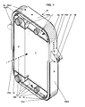
- Figures 1-6 show a heat exchanger arrangement in which the frame 10 consists of four angular frames 6c, 6d, 6e and 6f .
- the remaining figures relate to a heat exchanger arrangement which has a frame 10 comprising a first and a second approximately U-shaped frame 6a, 6b and to a heat exchanger arrangement with two angular frames 6g, 6h .
- the heat exchanger arrangement is intended for motor vehicles, in which, according to FIGS.
- the header tanks 1 , 2 having heat exchangers 3 , 4 are arranged in a frame 10 in order to be flowed through by the cooling air KL, the frame 10 having means for Attachment of the heat exchangers 3 , 4 with their header boxes 1 , 2 at attachment points 11 and support bearings 12 are provided for supporting the arrangement in the motor vehicle.
- the support bearings 12 are attached to the frame 10 on the left and right.
- the frame 10 consists of frame parts 6c, 6d, 6e, 6f , which frame at least one heat exchanger, the frame 10 being adjustable in size in the direction of extent of the longitudinal and transverse sides 15 of the frame 10 .
- the designation "long sides” and “short sides” only serves to differentiate the sides and in any case says nothing about their length. For example, both sides can have the same length.
- the direction of extension of the longitudinal and transverse sides 15 is identical to that of the matching legs of the frame parts.
- the frame 10 is formed here from four angular frames 6c, 6d, 6e, 6f forming the longitudinal and transverse sides 15 , which together frame two heat exchangers 3, 4 , the frame 10 in the direction of extension of the first legs 15c1, 15d1, 15e1, 15f1 (Long side) of the angle frame 6c, 6d, 6e, 6f and in the direction of extension of the second leg 15c2, 15d2, 15e2, 15f2 (transverse side) the angle frame 6c, 6d, 6e, 6f is adjustable.
- the heat exchangers 3, 4 are only arranged next to one another in FIGS. 1-6.
- the arrangement could also have heat exchangers arranged one behind the other, as is shown in principle in the other figures described below.
- All the angular frames 6c, 6d, 6e, 6f are identical, which can be seen by looking at FIG. 3, in which no heat exchangers have been drawn in, in order to make this situation easier to recognize.
- Each angular frame 6c, 6d, 6e, 6f has a strut 40 .
- FIG. 4 shows a single angular frame, which is designated 6e , for example.
- the angular frame 6e has a first leg 15e1 and a second leg 15e2 in an identical design to the other angular frames 6c, 6d, 6f .
- the leg 15e2 which is vertical in the picture, preferably — but not necessarily — has a larger cross section than the leg 15e1 and is designed as a hollow profile. In versions not shown, it is e.g. B. a U profile.
- the interlocking legs 15 of the angular frames 6c, d, e, f are held at least in one direction - here in the direction of flow of the cooling air KL - by positive locking, which is achieved by a hollow profile or, for example, by a U-profile-like configuration one of the legs 15 is reached.
- a hollow profile In the hollow profile shown there is a slot 41, running in the longitudinal direction of the leg 15e2 .
- the above-mentioned strut 40 lies in one plane with the slot 41 and, for connection to the hollow profile, is forked into two arms 42 and 43 to a sufficient length.
- Such a fork and the slot 41 are not necessary if, instead of the hollow profile, a U-shaped profile or a differently designed guide of the one leg 15/1 in the other leg 15/2 is chosen which is known to the person skilled in the art.
- One arm 42 ends at one edge of the slot 41 and the other arm 43 ends at the other edge of the slot 41.
- the strut 40 is formed with only one arm. In the assembled state, the one-armed piece of the strut 40 of the one angular frame 6c can be pushed between the arms 42, 43 of the strut 40 of the adjacent angular frame, so that the struts 40 of the adjacent angular frame can cross, as for example from FIGS.
- FIG. 5 the direction of movement of the angular frame during assembly or disassembly has been indicated by an arrow. 4, where there is another slot 50 in the horizontal leg 15e1 , which also runs in the longitudinal direction of the leg 15e1 .
- This slot 50 used for the continuous size adjustment within certain limits its frame 10.
- a fastener 7 (Fig. 3, 5) are performed to accomplish the locking of the frame 10 in the desired size.
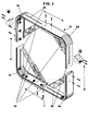
- 7 and 10 show another heat exchanger arrangement in which the frame 10 consists of two approximately U-shaped frames 6a and 6b and which is adjustable in size in the vertical direction. The direction of extension of the legs 15a , 15b of the frames 6a and 6b is therefore vertical.
- FIG. 7 is also an exploded illustration and therefore speaks largely from the illustration itself.
- the legs 15a of the upper frame 6a are located between the legs 15b of the lower frame 6b, on which the support bearings 12 are also arranged, because the lower frame 6b is more stable trained and therefore suitable to absorb the bearing forces well.
- the size adjustment is provided in stages, for which purpose there are openings 8 in the legs 15a which correspond to openings 9 in the legs 15b in certain setting positions.
- a fastening member 7 is attached in the corresponding openings 8, 9 .
- the person skilled in the art also has positive connections, such as latching connections or the like, which he may use in order to be able to dispense with fastening elements 7 .
- the lower frame 6b is made of plastic and the upper frame 6a is made of metal, for example aluminum sheet or sheet steel.
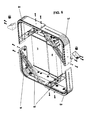
- the arrangement in FIG. 9 has a strut 14 between the legs 15b . Accordingly, an elongated cutout 21 is provided in the legs 15a , into which the strut 14 can slide when the two frames 6a, 6b are joined together.
- the left heat exchanger 3 was not drawn in FIG. 9 in order to allow a view of the strut. In this exemplary embodiment, heat exchangers can thus be seen in side-by-side and in front-to-back arrangement. Furthermore, the support of the arrangement in a motor vehicle on the longitudinal bars 70 of the vehicle frame was shown. Standard dampers 80 are provided.
- an enlarged section of an elastic fastening point 11 has been shown. According to this illustration, it is provided to punch an opening 13 in the cross struts 16 and to form a conical collar 19 around the opening 13 .
- a pin 17 which protrudes into the opening 13 , is arranged on the collecting box 1 of a heat exchanger, a vibration-damping element 18 being arranged between the pin 17 and the collar 19 of the opening 13 .
- This type of formation of an elastic fastening point 11 causes the heat exchangers to be held in a stable position and not to be additionally fastened.
- a certain preload of the frames 6a, 6b on the heat exchanger can be provided.
- a pan-like shape can also be provided, as was provided for the fastening points 11 of the arrangement described first, which can be seen in particular from the illustration according to FIG. 4.
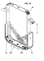
- Fig. 10 shows another solution, in which the frame 10 consists of two approximately L-shaped angle frames 6g, 6h , which fit together with one of their legs 15g1, 15h1 and enclose at least one heat exchanger 3, 4 from three sides, the The frame 10 is adjustable in size in the direction of extension of the two matching legs 15g1, 15h1 of the angle frame 6g, 6h , and the frame 10 can either be completed on the fourth side by means of a crossmember 90 or remains open on this side.
- the cross member 90 is U-shaped in the exemplary embodiment shown. This traverse 90 must be replaced if a different size of the frame 10 is to be set in the direction of the legs 15g1, 15h1 .
- the traverse 90 can be a part made from sheet metal.
- the frame 10 is designed in such a way that it saves space.
- the frame parts are therefore relatively flat, and they are arranged in the immediate vicinity of the outer contour of the heat exchanger.
Landscapes
- Engineering & Computer Science (AREA)
- Mechanical Engineering (AREA)
- Physics & Mathematics (AREA)
- Thermal Sciences (AREA)
- General Engineering & Computer Science (AREA)
- Chemical & Material Sciences (AREA)
- Combustion & Propulsion (AREA)
- Transportation (AREA)
- Cooling, Air Intake And Gas Exhaust, And Fuel Tank Arrangements In Propulsion Units (AREA)
- Mutual Connection Of Rods And Tubes (AREA)
Abstract
Description
Die Erfindung betrifft eine Wärmeübertrageranordnung für Kraftfahrzeuge, bei der die Sammelkästen besitzenden Wärmeübertrager in einer Umrahmung, bestehend aus Längs - und Querseiten, angeordnet sind und von der Kühlluft durchströmt werden, wobei die Umrahmung Mittel zur Befestigung der Wärmeübertrager an Befestigungspunkten aufweist und wobei Stützlager zur Abstützung der Anordnung im Kraftfahrzeug vorgesehen sind.The invention relates to a heat exchanger arrangement for motor vehicles, in which the A heat exchanger in a frame consisting of collecting boxes Longitudinal and transverse sides, are arranged and the cooling air flows through them, the frame means for attaching the heat exchanger Has attachment points and support bearings for supporting the arrangement are provided in the motor vehicle.
Diese Wärmeübertrageranordnung ist aus der internationalen Patentanmeldung
WO 99/47875 bekannt. Die Umrahmung besteht dort aus einem u - förmigen
Rahmen, der an den Innenseiten seiner beiden gegenüberliegenden Schenkel
Führungen besitzt, in die ein Wärmeübertrager eingeschoben werden kann. Die
Umrahmung wird dann durch eine zweite Querstrebe zu einer geschlossenen
Rahmenkonstruktion komplettiert. Es ist mit dieser bekannten Rahmenkonstruktion
der Wärmeübertrageranordnung nicht, oder nur mit aufwendigen Änderungen der
Rahmenkonstruktion, möglich, Wärmeübertrager unterschiedlicher Abmessungen
unterzubringen. Somit scheint die Flexibilität der Wärmeübertrageranordnung
verbesserungsbedürftig zu sein.
Weiterer Stand der Technik, der ebenfalls Rahmenkonstruktionen aufweist, ist der
Anmelderin beispielsweise aus EP 0 020 190, aus CA 1 081 277, aus DE 100 61 561
A1 oder aus DE 195 14 016 C1 bekannt. Der beschriebene Nachteil trifft mehr oder
weniger auch auf die Anordnungen aus den vorstehend genannten Dokumenten zu.
In der kürzlich angemeldeten DE 102 50 334.6 wird ein geschlossener, einstückiger
Rahmen aus Kunststoff eingesetzt, der es offensichtlich nicht gestattet,
Wärmeübertrager vorzusehen, die nicht in den Umfang der Umrahmung
hineinpassen.This heat exchanger arrangement is known from international patent application WO 99/47875. The frame there consists of a U-shaped frame, which has guides on the inside of its two opposite legs, into which a heat exchanger can be inserted. The frame is then completed by a second cross strut to form a closed frame construction. It is not possible with this known frame construction of the heat exchanger arrangement, or only with complex changes to the frame construction, to accommodate heat exchangers of different dimensions. The flexibility of the heat exchanger arrangement therefore seems to be in need of improvement.
Further prior art, which also has frame structures, is known to the applicant, for example from EP 0 020 190, from CA 1 081 277, from DE 100 61 561 A1 or from DE 195 14 016 C1. The disadvantage described more or less also applies to the arrangements from the documents mentioned above. In the recently registered DE 102 50 334.6, a closed, one-piece frame made of plastic is used, which obviously does not allow heat exchangers to be provided which do not fit into the scope of the frame.
Die Aufgabe der Erfindung besteht demzufolge darin, eine
Wärmeübertrageranordnung zur Verfügung zu stellen, deren Rahmenkonstruktion
eine bessere Flexibilität zulässt, so dass beispielsweise eine gesamte Baureihe von
Kraftfahrzeugen mit einer Wärmeübertrageranordnung ausgerüstet werden kann, die
die gleiche Rahmenkonstruktion aufweist.
Diese Aufgabe wird bei einer dem Oberbegriff entsprechenden
Wärmeübertrageranordnung erfindungsgemäß durch die Merkmale im Kennzeichen
des Anspruchs 1 gelöst. Die Umrahmung besteht aus Rahmenteilen, die wenigstens
einen Wärmeübertrager umrahmen, wobei die Umrahmung in Erstreckungsrichtung
wenigstens einer der Längs - und / oder Querseiten der Umrahmung
größenverstellbar ist.The object of the invention is therefore to provide a heat exchanger arrangement, the frame construction of which allows better flexibility, so that, for example, an entire series of motor vehicles can be equipped with a heat exchanger arrangement which has the same frame construction.
This object is achieved according to the invention in a heat exchanger arrangement corresponding to the preamble by the features in the characterizing part of claim 1. The frame consists of frame parts which frame at least one heat exchanger, the frame being adjustable in size in the direction of extension of at least one of the longitudinal and / or transverse sides of the frame.
Gemäß einem Ausführungsbeispiel ist vorgesehen, dass die Umrahmung aus einem
ersten etwa u - förmigen Rahmen und einem zweiten etwa u - förmigen Rahmen
besteht, die zusammenpassen, um wenigstens einen Wärmeübertrager zu
umrahmen, wobei die aus den beiden Rahmen bestehende Umrahmung in
Erstreckungsrichtung der Schenkel der Rahmen größenverstellbar ist.
Die Schenkel der beiden Rahmen sind in entsprechenden Positionen vorzugsweise
lösbar zu verbinden.
Die Querstrebe des zweiten u-förmigen Rahmens ist geringfügig kürzer als die
Querstrebe des ersten u - förmigen Rahmens, so dass der zweite Rahmen in den
ersten Rahmen hineinpasst. Die Möglichkeit zur Größenverstellung der
Rahmenkonstruktion schafft die Voraussetzungen dafür, beispielsweise für leichte,
mittlere und schwere Lastkraftwagen, die gleiche Rahmenkonstruktion einzusetzen,
deren Herstellung deshalb wesentlich kostengünstiger erfolgen kann. Bei leichten
Lastkraftwagen sind wegen der geringeren Motorleistung kleinere Wärmeübertrager
vorzusehen, wobei dann beide Rahmen so weit zusammengeschoben und in dieser
Position an ihren Schenkeln lösbar verbunden sind, dass sie z. B. die kleinstmögliche
Fläche einschließen. Umgekehrt kann bei schweren Lastkraftwagen mit wesentlich
größeren Wärmeübertragern die lösbare Verbindung so erfolgen, dass z. B. die
größtmögliche Fläche von beiden Rahmen umfasst wird. Die Position der lösbaren
Verbindung der Schenkel ist veränderbar.
Die lösbare Verbindung der Schenkel kann so ausgebildet sein, dass mittels der
Umrahmung eine Vorspannkraft auf den mindestens einen Wärmeübertrager
ausgeübt wird. Auf jeden Fall sollte sichergestellt sein, dass sich die
Wärmeübertrager im Betrieb nicht wesentlich bewegen können, d. h, dass sie nicht
aus den elastischen Befestigungspunkten herausrutschen können.
Tragarme oder dergleichen Befestigungselemente an den Wärmeübertragerrn sind
nicht unbedingt notwendig.
Die Schenkel eines u - förmigen Rahmens sind etwa gleich lang, wobei die Schenkel
des einen Rahmens länger sind als die Schenkel des anderen Rahmens. According to one embodiment, it is provided that the frame consists of a first approximately U-shaped frame and a second approximately U-shaped frame which fit together to frame at least one heat exchanger, the frame consisting of the two frames in the direction of extension of the legs of the Frame is adjustable in size.
The legs of the two frames are preferably releasably connected in corresponding positions.
The cross strut of the second U-shaped frame is slightly shorter than the cross strut of the first U-shaped frame, so that the second frame fits into the first frame. The possibility of adjusting the size of the frame construction creates the prerequisites for this, for example for light, medium and heavy trucks, to use the same frame construction, which can therefore be manufactured much more cost-effectively. In light trucks, smaller heat exchangers are to be provided because of the lower engine power, in which case both frames are pushed together so far and are releasably connected to their legs in this position that they are connected, for. B. Include the smallest possible area. Conversely, in the case of heavy goods vehicles with much larger heat exchangers, the releasable connection can take place in such a way that, for. B. the largest possible area is encompassed by both frames. The position of the detachable connection of the legs can be changed.
The releasable connection of the legs can be designed such that a pretensioning force is exerted on the at least one heat exchanger by means of the frame. In any case, it should be ensured that the heat exchangers cannot move significantly during operation. h that they cannot slip out of the elastic fastening points.
Support arms or similar fasteners on the heat exchangers are not absolutely necessary.
The legs of a U-shaped frame are approximately the same length, the legs of one frame being longer than the legs of the other frame.
Die Schenkel eines Rahmens können alternativ auch unterschiedliche Länge
besitzen. In diesem Fall werden die beiden Rahmen so zusammengefügt, dass der
längere Schenkel des einen Rahmens mit dem kürzeren Schenkel des anderen
Rahmens korrespondiert.
Es ist weiter vorteilhaft, wenigstens einen der u - förmigen Rahmen mit einer
Verstrebung zwischen seinen Schenkeln auszurüsten, um die notwendige Stabilität
der Rahmenkonstruktion zu gewährleisten.
Die Befestigungspunkte des mindestens einen Wärmeübertragers sind innerhalb der
Umrahmung elastisch ausgebildet und ansonsten ist keine weitere Befestigung des
Wärmeübertragers an der Umrahmung erforderlich. Die Elastizität ist so gewählt,
dass nicht nur eine vibrationsreduzierte Lagerung der Wärmeübertrager erreicht wird,
sondern auch deren thermisch bedingten Längenänderungen berücksichtigt, d. h.,
zugelassen werden. Falls eine Vorspannkraft mittels der Umrahmung auf den
Wärmeübertrager ausgeübt wird, sollte die elastische Befestigung so ausgelegt sein,
dass auch dann die thermisch bedingten Längenänderungen möglich sind. Als
elastische Befestigung können deshalb auch Federelemente zum Einsatz kommen.
Vorzugsweise sind die Wärmeübertrager mit oben und unten liegenden
Sammelkästen angeordnet und die elastischen Befestigungspunkte sind zwischen
den Sammelkästen und den Querstreben der beiden Rahmen anzutreffen.
Grundsätzlich ist es natürlich auch möglich die elastischen Befestigungspunkte
zwischen den die Sammelkästen gewöhnlich an den Seite verbindenden Seitenteilen
und der Umrahmung vorzusehen. Dies kann dann der Fall sein, wenn sogenannte
Querstrom - Wärmeübertrager vorgesehen werden, bei denen die Sammelkästen
vertikal, d. h. links und rechts des Wärmeübertragers, angeordnet sind.
Jeder elastische Befestigungspunkt besteht vorzugsweise aus einer Öffnung mit
einem konischen Rand, in die ein korrespondierend geformter Zapfen hineinragt,
wobei zwischen dem Zapfen und dem Rand der Öffnung ein
schwingungsdämpfender Werkstoff, beispielsweise Gummi, oder ein Federelement,
eingefügt ist. Es muss sich allerdings nicht unbedingt um eine Öffnung handeln. Die
gleiche Wirkung kann mit einer Ausbuchtung oder dergleichen vorzugsweise
konischen Verformung erzielt werden, in die der Zapfen eingreifen kann.
Die lösbare Verbindung zwischen den Schenkeln der Rahmen kann entweder so
ausgebildet sein, dass eine stufenlose Größenverstellung erfolgen kann oder so,
dass eine Größenverstellung in vorgegebenen Stufen möglich wird. The legs of a frame can alternatively have different lengths. In this case, the two frames are joined together in such a way that the longer leg of one frame corresponds to the shorter leg of the other frame.
It is further advantageous to equip at least one of the U-shaped frames with a strut between its legs in order to ensure the necessary stability of the frame construction.
The fastening points of the at least one heat exchanger are designed to be elastic within the frame and otherwise no further fastening of the heat exchanger to the frame is required. The elasticity is selected so that not only is the heat exchanger mounted in a vibration-reduced manner, but also its thermal changes in length are taken into account, that is, are permitted. If a pretensioning force is exerted on the heat exchanger by means of the frame, the elastic fastening should be designed in such a way that the thermally induced length changes are also possible. Spring elements can therefore also be used as elastic fastening.
The heat exchangers are preferably arranged with header boxes at the top and bottom and the elastic fastening points can be found between the header boxes and the cross struts of the two frames.
In principle, it is of course also possible to provide the elastic fastening points between the side parts which usually connect the collecting boxes on the side and the frame. This can be the case if so-called cross-flow heat exchangers are provided, in which the header boxes are arranged vertically, ie to the left and right of the heat exchanger.
Each elastic fastening point preferably consists of an opening with a conical edge into which a correspondingly shaped pin protrudes, a vibration-damping material, for example rubber, or a spring element being inserted between the pin and the edge of the opening. However, it does not necessarily have to be an opening. The same effect can be achieved with a bulge or the like, preferably conical deformation, in which the pin can engage.
The detachable connection between the legs of the frame can either be designed in such a way that a stepless size adjustment can take place or in such a way that a size adjustment in predetermined steps is possible.
Beide Rahmen können aus Kunststoff bestehen, wobei einer der Rahmen
Verstärkungen in seinen Schenkeln aufweisen kann.
Ferner kann ein Rahmen aus Kunststoff und der zweite Rahmen aus Metall
bestehen.
Die Wärmeübertrager können nebeneinander (side by side) und/oder in
Strömungsrichtung der Kühlluft hintereinander (front to back) in der Umrahmung
angeordnet sein, und sie sind vorzugsweise ausschließlich über elastische
Befestigungspunkte mit der Umrahmung verbunden.Both frames can be made of plastic, and one of the frames can have reinforcements in its legs.
Furthermore, a frame made of plastic and the second frame made of metal.
The heat exchangers can be arranged side by side and / or one behind the other in the direction of flow of the cooling air (front to back) in the frame, and they are preferably connected to the frame exclusively via elastic fastening points.
Wie aus den beschriebenen Merkmalen hervorgeht, ist die Größenverstellung der
Umrahmung bei diesem Ausführungsbeispiel in einer Richtung, vorzugsweise in der
vertikalen Richtung, vorgesehen.
Ein weiteres Ausführungsbeispiel sieht demgegenüber eine Größenverstellung der
Umrahmung in der vertikalen und in der horizontalen Richtung vor, und es bietet
deshalb hinsichtlich Flexibilität noch mehr Vorteile als das erste Ausführungsbeispiel.
Es benötigt vier Winkelrahmen, die gemeinsam die Umrahmung bilden, und es ist
deshalb möglicherweise etwas aufwendiger als das erste Beispiel, bei dem lediglich
zwei einstückige Rahmen vorhanden sind. Bezüglich der Kostenaufwendungen soll
allerdings darauf aufmerksam gemacht werden, dass die vier Winkelrahmen absolut
identisch sein können, wodurch ein wesentlicher Einfluss auf die Senkung der
Herstellungskosten genommen werden kann.
Ein anderes Ausführungsbeispiel sieht vor, dass die Umrahmung aus zwei
Winkelrahmen besteht, die mit einem ihrer Schenkel zusammenpassen und
wenigstens einen Wärmeübertrager von drei Seiten einfassen, wobei die
Umrahmung in Erstreckungsrichtung der zusammenpassenden Schenkel der
Winkelrahmen größenverstellbar ist, und wobei die Umrahmung entweder an der
vierten Seite mittels einer Traverse komplettierbar ist oder an dieser Seite offen
bleibt. Mit diesem Ausführungsbeispiel, dass zwei L-förmige Winkelrahmen vorsieht,
erfolgt die Größenverstellung wiederum nur in einer Richtung, die hier aber - im
Gegensatz zum ersten Ausführungsbeispiel - die horizontale Richtung ist.As can be seen from the features described, the size adjustment of the frame in this embodiment is provided in one direction, preferably in the vertical direction.
In contrast, a further exemplary embodiment provides for a size adjustment of the frame in the vertical and in the horizontal direction, and it therefore offers even more advantages in terms of flexibility than the first exemplary embodiment. It takes four angular frames that together form the frame, and it may therefore be somewhat more complex than the first example, where there are only two one-piece frames. Regarding the cost, however, it should be noted that the four angular frames can be absolutely identical, which can have a significant impact on the reduction in manufacturing costs.
Another exemplary embodiment provides that the frame consists of two angular frames which fit together with one of their legs and enclose at least one heat exchanger from three sides, the frame being adjustable in size in the direction of extension of the matching legs, and the frame either on the fourth Side can be completed by means of a traverse or remains open on this side. With this exemplary embodiment, which provides two L-shaped angular frames, the size is again only adjusted in one direction, which, however, in contrast to the first exemplary embodiment, is the horizontal direction.
Wegen weiterer Merkmale wird auf die Patentansprüche hingewiesen.
Die Erfindung wird nachfolgend in Ausführungsbeispielen unter Bezugnahme auf die
beiliegenden Zeichnungen beschrieben. Aus der folgenden Beschreibung gehen
weitere Merkmale und Wirkungen hervor, die sich gegebenenfalls als besonders
wichtig erweisen können.For further features, reference is made to the claims.
The invention is described below in exemplary embodiments with reference to the accompanying drawings. From the following description further features and effects emerge which may prove to be particularly important.
Die beigefügten Figuren zeigen Folgendes:
- Fig. 1
- Perspektivansicht auf eine Wärmeübertrageranordnung, von einer Seite gesehen;
- Fig. 2
- Perspektivansicht auf die Anordnung, von der anderen Seite gesehen;
- Fig. 3
- Explosionsdarstellung auf die Umrahmung ohne Wärmeübertrager;
- Fig. 4
- Perspektivansicht auf einen Winkelrahmen;
- Fig. 5
- Explosionsdarstellung eines Ausschnittes der Umrahmung;
- Fig. 6
- Explosionsdarstellung der Wärmeübertrageranordnung aus Fig. 2;
- Fig. 7
- Wärmeübertrageranordnung in side - by - side - Anordnung
- Fig. 8
- Detailansicht eines Befestigungspunktes;
- Fig. 9
- Wärmeübertageranordnung in side-by-side - und in front-to-back -Anordnung in einem zweiten Ausführungsbeispiel
- Fig.10
- Explosionsdarstellung eines dritten Ausführungsbeispiels
- Fig. 1
- Perspective view of a heat exchanger assembly, seen from one side;
- Fig. 2
- Perspective view of the arrangement seen from the other side;
- Fig. 3
- Exploded view of the frame without heat exchanger;
- Fig. 4
- Perspective view of an angle frame;
- Fig. 5
- Exploded view of a section of the frame;
- Fig. 6
- Exploded view of the heat exchanger arrangement from Fig. 2;
- Fig. 7
- Heat exchanger arrangement in side - by - side arrangement
- Fig. 8
- Detailed view of an attachment point;
- Fig. 9
- Heat exchanger arrangement in side-by-side - and in front-to-back arrangement in a second embodiment
- Figure 10
- Exploded view of a third embodiment
Die Figuren 1 - 6 zeigen eine Wärmeübertrageranordnung, bei der die Umrahmung
10 aus vier Winkelrahmen 6c, 6d, 6e und 6f besteht. Die restlichen Figuren beziehen
sich auf eine Wärmeübertrageranordnung, die eine Umrahmung 10 aus einem ersten
und einem zweiten etwa u-förmigen Rahmen 6a, 6b aufweist und auf eine
Wärmeübertrageranordnung mit zwei Winkelrahmen 6g, 6h.
Die Wärmeübertrageranordnung ist für Kraftfahrzeuge gedacht, bei der, gemäß den
Fig. 1 - 6, die Sammelkästen 1, 2 besitzenden Wärmeübertrager 3, 4 in einer
Umrahmung 10 angeordnet sind, um von der Kühlluft KL durchströmt zu werden,
wobei die Umrahmung 10 Mittel zur Befestigung der Wärmeübertrager 3, 4 mit ihren
Sammelkästen 1, 2 an Befestigungspunkten 11 aufweist und wobei Stützlager 12 zur
Abstützung der Anordnung im Kraftfahrzeug vorgesehen sind. Die Stützlager 12 sind
links und rechts an der Umrahmung 10 befestigt. Die Umrahmung 10 besteht aus
Rahmenteilen 6c, 6d, 6e, 6f, die wenigstens einen Wärmeübertrager umrahmen,
wobei die Umrahmung 10 in Erstreckungsrichtung der Längs - und der Querseiten 15
der Umrahmung 10 größenverstellbar ist. Die Bezeichnung "Längsseiten" und
"Querseiten" dient lediglich der Unterscheidung der Seiten und sagt jedenfalls nichts
über deren Länge aus. Beide Seiten können beispielsweise durchaus die gleiche
Länge besitzen. Figures 1-6 show a heat exchanger arrangement in which the
The heat exchanger arrangement is intended for motor vehicles, in which, according to FIGS. 1-6, the
Die Erstreckungsrichtung der Längs - und Querseiten 15 ist identisch mit derjenigen
der zusammenpassenden Schenkel der Rahmenteile.
Die Umrahmung 10 wird hier aus vier die Längs - und Querseiten 15 bildenden
Winkelrahmen 6c, 6d, 6e, 6f gebildet, die gemeinsam zwei Wärmeübertrager 3, 4
umrahmen, wobei die Umrahmung 10 in der Erstreckungsrichtung der ersten
Schenkel 15c1, 15d1, 15e1, 15f1 (Längsseite) der Winkelrahmen 6c, 6d, 6e, 6f und
in der Erstreckungsrichtung der zweiten Schenkel 15c2, 15d2, 15e2, 15f2
(Querseite) der Winkelrahmen 6c, 6d, 6e, 6f größenverstellbar ist. Die
Wärmeübertrager 3, 4 sind in den Figuren 1 - 6 lediglich nebeneinander angeordnet.
Die Anordnung könnte zusätzlich auch hintereinander angeordnete Wärmeübertrager
aufweisen, wie das in den anderen, weiter unten beschriebenen, Figuren prinzipiell
gezeigt ist.
Sämtliche Winkelrahmen 6c, 6d, 6e, 6f sind identisch, was durch einen Blick auf die
Fig. 3 erkennbar ist, in der keine Wärmeübertrager eingezeichnet wurden, um diesen
Sachverhalt einfacher erkennbar zu machen. Man kann, beispielsweise beim rechten
oberen Winkelrahmen 6d beginnend, in Gedanken im Uhrzeigersinn oder entgegen
demselben um die Umrahmung 10 herumfahren und den Winkelrahmen 6d dreimal
jeweils um 90° drehen, und man wird dabei feststellen, dass die Winkelrahmen
identisch ausgebildet sind. Jeder Winkelrahmen 6c, 6d, 6e, 6f besitzt eine
Verstrebung 40. In der Fig. 4 wurde eine einzelner Winkelrahmen abgebildet, der
beispielsweise mit 6e bezeichnet ist. Der Winkelrahmen 6e besitzt in mit den
anderen Winkelrahmen 6c, 6d, 6f identischer Ausbildung, einen ersten Schenkel
15e1 und einen zweiten Schenkel 15e2. Der im Bild vertikale Schenkel 15e2 besitzt
vorzugsweise - aber nicht notwendigerweise - einen größeren Querschnitt als der
Schenkel 15e1 und ist als Hohlprofil ausgebildet. In nicht gezeigten Ausführungen
handelt es sich z. B. um ein U - Profil. Es kann als vorteilhaft angesehen werden,
wenn die ineinandergreifenden Schenkel 15 der Winkelrahmen 6c, d, e, f wenigstens
in einer Richtung - hier in Strömungsrichtung der Kühlluft KL - durch Formschluss
gehalten werden, was durch ein Hohlprofil oder beispielsweise durch eine U -
profilartige Ausbildung eines der Schenkel 15 erreicht wird. In dem gezeigten
Hohlprofil befindet sich ein Schlitz 41, in Längsrichtung des Schenkels 15e2
verlaufend. Die erwähnte Verstrebung 40 liegt in einer Ebene mit dem Schlitz 41, und
sie ist zum Anschluss an das Hohlprofil weisend in ausreichender Länge in zwei
Arme 42 und 43 aufgegabelt. Eine solche Aufgabelung und der Schlitz 41 sind nicht
notwendig, wenn anstelle des Hohlprofils ein U - Profil oder eine dem Fachmann
geläufige, andersartig ausgebildete Führung des einen Schenkels 15/1 in dem
anderen Schenkel 15/2 gewählt wird. Der eine Arm 42 endet an dem einen Rand des
Schlitzes 41 und der andere Arm 43 endet an dem anderen Rand des Schlitzes 41.
Im Anschlussbereich an den im Bild horizontalen Schenkel 15e1 ist die Verstrebung
40 lediglich einarmig ausgebildet. Im montierten Zustand kann das einarmige Stück
der Verstrebung 40 des einen Winkelrahmens 6c zwischen die Arme 42, 43 der
Verstrebung 40 des benachbarten Winkelrahmens geschoben werden, so dass sich
die Verstrebungen 40 der benachbarten Winkelrahmen überkreuzen können, wie
beispielsweise aus den Fig. 2 und 5 sehr gut zu sehen ist. In Fig. 5 ist durch einen
Pfeil die Bewegungsrichtung der Winkelrahmen bei der Montage bzw. Demontage
angezeigt worden.
Zurück zur Fig. 4, wo sich in dem horizontalen Schenkel 15e1 ein weiterer Schlitz 50
befindet, der ebenfalls in Längsrichtung des Schenkels 15e1 verläuft. Dieser Schlitz
50 dient der stufenlosen Größenverstellung innerhalb gewisser Grenzen der
Umrahmung 10. Durch diesen Schlitz 50 hindurch kann z. B. ein Befestigungsorgan
7 (Fig. 3, 5) geführt werden, um die Arretierung der Umrahmung 10 in der
gewünschten Größe zu bewerkstelligen.
Die Fig. 7 und 10 zeigen eine andere Wärmeübertrageranordnung, bei der die
Umrahmung 10 aus zwei etwa U - förmigen Rahmen 6a und 6b besteht und die in
vertikaler Richtung größenverstellbar ist. Die Erstreckungsrichtung der Schenkel 15a,
15b der Rahmen 6a und 6b ist also vertikal verlaufend. Die Fig. 7 ist ebenfalls eine
Explosionsdarstellung und spricht deshalb weitgehend aus der Darstellung selbst.
Die Schenkel 15a des oberen Rahmens 6a befinden sich zwischen den Schenkeln
15b des unteren Rahmens 6b, an dem auch die Stützlager 12 angeordnet sind, weil
der untere Rahmen 6b stabiler ausgebildet und deshalb geeignet ist, die Lagerkräfte
gut aufzunehmen. Im weiteren Unterschied zur vorne beschriebenen
Wärmeübertrageranordnung, ist hier die Größenverstellung in Stufen vorgesehen,
wozu in den Schenkeln 15a Öffnungen 8 vorhanden sind, die in bestimmten
Einstellpositionen mit Öffnungen 9 in den Schenkeln 15b übereinstimmen. Ein
Befestigungsorgan 7 wird in den übereinstimmenden Öffnungen 8, 9 angebracht.
Dem Fachmann stehen allerdings auch formschlüssige Verbindungen, wie
beispielsweise Rastverbindungen o. ä. zur Verfügung, die er gegebenenfalls
einsetzen wird, um auf Befestigungsorgane 7 verzichten zu können. Der untere
Rahmen 6b besteht aus Kunststoff und der obere Rahmen 6a besteht aus Metall,
beispielsweise aus Aluminiumblech oder aus Stahlblech. Die Anordnung in der Fig. 9
besitzt zwischen den Schenkeln 15b eine Verstrebung 14. In den Schenkeln 15a ist
demzufolge ein länglicher Ausschnitt 21 vorhanden, in den die Verstrebung 14 beim
Zusammenfügen beider Rahmen 6a, 6b hineingleiten kann. Der linke
Wärmeübertrager 3 wurde in der Fig. 9 nicht gezeichnet, um den Blick auf die
Verstrebung zu gestatten. In diesem Ausführungsbeispiel sind also Wärmeübertrager
in side - by - side und in front - to - back -Anordnung zu sehen. Ferner wurde dort
die Abstützung der Anordnung in einem Kraftfahrzeug an den Längsholmen 70 des
Fahrzeugrahmens gezeigt. Es sind standardmäßige Dämpfer 80 vorgesehen.
In Fig. 8 wurde ein vergrößerter Ausschnitt eines elastischen Befestigungspunktes
11 dargestellt. Nach dieser Abbildung ist vorgesehen, beispielsweise in den
Querstreben 16 eine Öffnung 13 zu stanzen und einen konischen Kragen 19 um die
Öffnung 13 herum auszubilden. Am Sammelkasten 1 eines Wärmeübertragers ist ein
Zapfen 17 angeordnet, der in die Öffnung 13 hineinragt, wobei ein
schwingungsdämpfendes Element 18 zwischen dem Zapfen 17 und dem Kragen 19
der Öffnung 13 angeordnet ist. Diese Art der Ausbildung eines elastischen
Befestigungspunktes 11 bewirkt, dass die Wärmeübertrager stabil in ihrer Position
gehalten werden und nicht zusätzlich zu befestigen sind. Eine gewisse Vorspannung
der Rahmen 6a, 6b auf die Wärmeübertrager kann vorgesehen werden. Es kann
anstelle der Öffnung 11 auch eine pfannenartige Ausformung vorgesehen werden,
wie es bei den Befestigungspunkten 11 der zuerst beschriebenen Anordnung
vorgesehen wurde, was insbesondere aus der Abbildung gemäß Fig. 4 zu sehen ist.The direction of extension of the longitudinal and transverse sides 15 is identical to that of the matching legs of the frame parts.
The
All the
4, where there is another
7 and 10 show another heat exchanger arrangement in which the
8, an enlarged section of an
Die Fig. 10 zeigt eine andere Lösung, bei der die Umrahmung 10 aus zwei etwa L -
förmigen Winkelrahmen 6g, 6h besteht, die mit je einem ihrer Schenkel 15g1, 15h1
zusammenpassen und wenigstens einen Wärmeübertrager 3, 4 von drei Seiten
einfassen, wobei die Umrahmung 10 in Erstreckungsrichtung der zwei
zusammenpassenden Schenkel 15g1, 15h1 der Winkelrahmen 6g, 6h
größenverstellbar ist, und wobei die Umrahmung 10 entweder an der vierten Seite
mittels einer Traverse 90 komplettierbar ist oder an dieser Seite offen bleibt. Die
Traverse 90 ist im gezeigten Ausführungsbeispiel u - förmig ausgebildet. Diese
Traverse 90 muss ausgetauscht werden, falls in Richtung der Schenkel 15g1, 15h1
eine andere Größe der Umrahmung 10 eingestellt werden soll. Dies ist jedoch kein
wesentlicher Aufwand, da es sich bei der Traverse 90 um ein aus Blech hergestelltes
Teil handeln kann.
Die Umrahmung 10 ist in allen Ausführungsbeispielen so gestaltet, dass sie
raumsparend ist. Die Rahmenteile sind deshalb relativ flach ausgebildet, und sie sind
in unmittelbarer Nähe der äußeren Kontur der Wärmeübertrager angeordnet.Fig. 10 shows another solution, in which the
In all exemplary embodiments, the
Claims (29)
dadurch gekennzeichnet, dass
die Umrahmung (10) aus Rahmenteilen (6a, 6b, oder 6c, 6d, 6e, 6f, oder 6g, 6h) besteht, die wenigstens einen Wärmeübertrager umrahmen, wobei die Umrahmung (10) in Erstreckungsrichtung in wenigstens einer der Längs - und / oder Querseiten (15) der Umrahmung (10) größenverstellbar ist.Heat exchanger arrangement for motor vehicles, in which the heat exchangers (3, 4, 5) which have the collecting tanks (1, 2) are arranged in a frame (10) consisting of longitudinal and transverse sides and through which the cooling air (KL) flows, the Frame (10) has means for fastening the heat exchangers (3, 4, 5) to fastening points (11) and support bearings (12) are provided to support the arrangement in the motor vehicle,
characterized in that
the frame (10) consists of frame parts (6a, 6b, or 6c, 6d, 6e, 6f, or 6g, 6h) which frame at least one heat exchanger, the frame (10) in the direction of extension in at least one of the longitudinal and / or transverse sides (15) of the frame (10) is adjustable in size.
die Umrahmung (10) aus Winkelrahmenteilen (6g, 6h) besteht, die mit einem ihrer Schenkel (15g1, 15h1) zusammenpassen und wenigstens einen Wärmeübertrager (3, 4) von drei Seiten einfassen, wobei die Umrahmung (10) in Erstreckungsrichtung der zusammenpassenden Schenkel (15g1, 15h1) der Winkelrahmenteile (6g, 6h) größenverstellbar ist, und wobei die Umrahmung (10) an der vierten Seite mittels einer Traverse (90) komplettierbar ist.Heat exchanger arrangement for motor vehicles according to claim 1, characterized in that
the frame (10) consists of angular frame parts (6g, 6h) which fit together with one of their legs (15g1, 15h1) and enclose at least one heat exchanger (3, 4) from three sides, the frame (10) in the direction of extension of the matching legs (15g1, 15h1) of the angular frame parts (6g, 6h) is adjustable in size, and the frame (10) on the fourth side can be completed by means of a crossmember (90).
Applications Claiming Priority (2)
| Application Number | Priority Date | Filing Date | Title |
|---|---|---|---|
| DE10316614A DE10316614A1 (en) | 2003-04-11 | 2003-04-11 | Heat exchanger arrangement for motor vehicles |
| DE10316614 | 2003-04-11 |
Publications (2)
| Publication Number | Publication Date |
|---|---|
| EP1469272A2 true EP1469272A2 (en) | 2004-10-20 |
| EP1469272A3 EP1469272A3 (en) | 2007-12-26 |
Family
ID=32892329
Family Applications (1)
| Application Number | Title | Priority Date | Filing Date |
|---|---|---|---|
| EP04004304A Withdrawn EP1469272A3 (en) | 2003-04-11 | 2004-02-26 | Heat exchange device for automobiles |
Country Status (3)
| Country | Link |
|---|---|
| US (1) | US20040200598A1 (en) |
| EP (1) | EP1469272A3 (en) |
| DE (1) | DE10316614A1 (en) |
Cited By (3)
| Publication number | Priority date | Publication date | Assignee | Title |
|---|---|---|---|---|
| CN101749965A (en) * | 2008-12-19 | 2010-06-23 | 卡特彼勒公司 | Cooling component for machine, machine and assembling method thereof |
| DE102009031695A1 (en) * | 2009-07-04 | 2011-01-05 | Modine Manufacturing Co., Racine | Cooling module for vehicle, has displacing mechanism provided with rails, where module is arranged on mechanism and one of rails is partially made of metal and forms bar of frame construction that is made of plastic |
| EP2620610A1 (en) * | 2012-01-30 | 2013-07-31 | Faurecia Bloc Avant | Motor vehicule front-end carrier comprising oblong opening and cooling module |
Families Citing this family (29)
| Publication number | Priority date | Publication date | Assignee | Title |
|---|---|---|---|---|
| DE102004044872A1 (en) * | 2004-09-14 | 2006-03-16 | Behr Gmbh & Co. Kg | Fastening arrangement for a charge air cooler, in particular a cooling module |
| DE102005039090A1 (en) * | 2005-08-06 | 2007-02-08 | Behr Gmbh & Co. Kg | Assembly support system |
| DE102005040721A1 (en) * | 2005-08-27 | 2007-03-01 | Modine Manufacturing Co., Racine | Cooling module and elastic bearing for it |
| JP4658157B2 (en) * | 2008-04-28 | 2011-03-23 | 豊田鉄工株式会社 | Vehicle cooling component support device |
| DE102009035085A1 (en) * | 2009-07-28 | 2011-02-10 | Behr Gmbh & Co. Kg | Mounting frame, heat exchanger assembly and vehicle |
| JP6048231B2 (en) * | 2013-03-11 | 2016-12-21 | マツダ株式会社 | Radiator support device for vehicle |
| DE102014226758A1 (en) | 2014-12-22 | 2016-06-23 | Volkswagen Aktiengesellschaft | Assembly carrier series as well as mounting carrier for mounting of cooler modules and method for the production of mounting supports |
| US9702638B2 (en) * | 2015-07-17 | 2017-07-11 | Spx Flow Technology Systems, Inc. | Frame for a heat exchanger |
| US10048023B2 (en) | 2015-08-27 | 2018-08-14 | Denso International America, Inc. | Heat exchanger shroud mount |
| US10514205B2 (en) | 2016-04-10 | 2019-12-24 | Forum Us, Inc. | Heat exchanger unit |
| US10480820B2 (en) | 2016-04-10 | 2019-11-19 | Forum Us, Inc. | Heat exchanger unit |
| US10545002B2 (en) | 2016-04-10 | 2020-01-28 | Forum Us, Inc. | Method for monitoring a heat exchanger unit |
| US10533881B2 (en) | 2016-04-10 | 2020-01-14 | Forum Us, Inc. | Airflow sensor assembly for monitored heat exchanger system |
| US10502597B2 (en) | 2016-04-10 | 2019-12-10 | Forum Us, Inc. | Monitored heat exchanger system |
| US11015871B2 (en) * | 2016-05-03 | 2021-05-25 | Carrier Corporation | Heat exchanger arrangement |
| US9751394B1 (en) | 2016-09-14 | 2017-09-05 | Caterpillar Inc. | Cooling package mounting assembly |
| JP6437981B2 (en) * | 2016-10-20 | 2018-12-12 | 本田技研工業株式会社 | Saddle riding vehicle |
| GB2558633A (en) * | 2017-01-12 | 2018-07-18 | Denso Marston Ltd | A heat exchanger assembly |
| JP6873403B2 (en) * | 2017-08-03 | 2021-05-19 | スズキ株式会社 | Vehicle front structure |
| US20190145719A1 (en) * | 2017-11-14 | 2019-05-16 | Valeo North America, Inc. | Exchanger frame and core assembly of a motor vehicle and methods of use thereof |
| EP3527799B1 (en) | 2018-02-20 | 2024-08-07 | Modine Manufacturing Company | Cooling module |
| FR3090508B1 (en) * | 2018-12-20 | 2022-06-24 | Valeo Systemes Thermiques | Motor vehicle thermal system |
| US11098962B2 (en) | 2019-02-22 | 2021-08-24 | Forum Us, Inc. | Finless heat exchanger apparatus and methods |
| US11946667B2 (en) | 2019-06-18 | 2024-04-02 | Forum Us, Inc. | Noise suppresion vertical curtain apparatus for heat exchanger units |
| CN111483314B (en) * | 2020-06-04 | 2024-06-25 | 浙江银轮机械股份有限公司 | Mounting frame and cooling device |
| CN112572139A (en) * | 2020-12-14 | 2021-03-30 | 房县诚信汽配有限责任公司 | Strap assembly for automobile shock absorption fuel tank |
| US20220307777A1 (en) * | 2021-03-23 | 2022-09-29 | Denso International America, Inc. | Heat exchanging system |
| FR3128494B1 (en) * | 2021-10-21 | 2023-10-20 | Valeo Systemes Thermiques | Support component and support of a heat exchanger obtained from an assembly of such support components |
| DE102022202610A1 (en) | 2022-03-16 | 2023-09-21 | Mahle International Gmbh | Heat exchanger assembly and vehicle with the same |
Citations (7)
| Publication number | Priority date | Publication date | Assignee | Title |
|---|---|---|---|---|
| US2481755A (en) * | 1947-08-06 | 1949-09-13 | Gilbert C Jones | Radiator clamp |
| US2575412A (en) * | 1948-03-22 | 1951-11-20 | Harry B Fechter | Auto radiator hanger clamp |
| DE7424066U (en) * | 1974-07-15 | 1974-11-28 | Schaefer Werke Kg | Holder for a panel radiator |
| DE4238017A1 (en) * | 1992-01-14 | 1993-07-15 | Sen Werner Mueller | Heating body quick clamp console - is adjustable for fitting heating body on wall and comprises long profile bar with fixture holes |
| US5360059A (en) * | 1988-10-06 | 1994-11-01 | Modine Manufacturing Company | Frame for a vehicular radiator |
| US6029345A (en) * | 1995-11-13 | 2000-02-29 | Alliedsignal Inc. | Radiator, charge air cooler and condenser mounting method |
| GB2355700A (en) * | 1999-10-27 | 2001-05-02 | Caterpillar Inc | Slidable heat-exchanger core elements for a mobile machine |
Family Cites Families (10)
| Publication number | Priority date | Publication date | Assignee | Title |
|---|---|---|---|---|
| US1432461A (en) * | 1921-04-22 | 1922-10-17 | Josef D Harris | Radiator for motor vehicles |
| US2147719A (en) * | 1934-08-17 | 1939-02-21 | Blanche R Simons | Vehicle radiator |
| US4230176A (en) * | 1978-04-24 | 1980-10-28 | Caterpillar Tractor Co. | Floating radiator tank top |
| US4382464A (en) * | 1981-08-12 | 1983-05-10 | Ex-Cell-O Corporation | Radiator |
| US4619313A (en) * | 1984-10-12 | 1986-10-28 | Touchstone Railway Supply & Mfg. Co., Inc. | Radiator frame unit |
| DE9213450U1 (en) * | 1992-10-06 | 1993-01-07 | Cummins Engine Co. Ltd., New Malden, Surrey | Drive unit |
| US5570738A (en) * | 1995-11-13 | 1996-11-05 | Alliedsignal Inc. | Radiator assembly for use in a motor vehicle |
| GB9805379D0 (en) * | 1998-03-14 | 1998-05-06 | Grayson Automotive Services Li | Heat exchanger assemblies for vehicles |
| US6105660A (en) * | 1998-11-02 | 2000-08-22 | Textron Inc. | Oil cooler movably supported on a vehicle and method for same |
| JP3903136B2 (en) * | 2001-11-05 | 2007-04-11 | 株式会社小松製作所 | Construction machine cooling system |
-
2003
- 2003-04-11 DE DE10316614A patent/DE10316614A1/en not_active Withdrawn
-
2004
- 2004-02-26 EP EP04004304A patent/EP1469272A3/en not_active Withdrawn
- 2004-03-31 US US10/813,740 patent/US20040200598A1/en not_active Abandoned
Patent Citations (7)
| Publication number | Priority date | Publication date | Assignee | Title |
|---|---|---|---|---|
| US2481755A (en) * | 1947-08-06 | 1949-09-13 | Gilbert C Jones | Radiator clamp |
| US2575412A (en) * | 1948-03-22 | 1951-11-20 | Harry B Fechter | Auto radiator hanger clamp |
| DE7424066U (en) * | 1974-07-15 | 1974-11-28 | Schaefer Werke Kg | Holder for a panel radiator |
| US5360059A (en) * | 1988-10-06 | 1994-11-01 | Modine Manufacturing Company | Frame for a vehicular radiator |
| DE4238017A1 (en) * | 1992-01-14 | 1993-07-15 | Sen Werner Mueller | Heating body quick clamp console - is adjustable for fitting heating body on wall and comprises long profile bar with fixture holes |
| US6029345A (en) * | 1995-11-13 | 2000-02-29 | Alliedsignal Inc. | Radiator, charge air cooler and condenser mounting method |
| GB2355700A (en) * | 1999-10-27 | 2001-05-02 | Caterpillar Inc | Slidable heat-exchanger core elements for a mobile machine |
Cited By (4)
| Publication number | Priority date | Publication date | Assignee | Title |
|---|---|---|---|---|
| CN101749965A (en) * | 2008-12-19 | 2010-06-23 | 卡特彼勒公司 | Cooling component for machine, machine and assembling method thereof |
| CN101749965B (en) * | 2008-12-19 | 2013-03-20 | 卡特彼勒公司 | Cooling component for machine, machine and assembling method thereof |
| DE102009031695A1 (en) * | 2009-07-04 | 2011-01-05 | Modine Manufacturing Co., Racine | Cooling module for vehicle, has displacing mechanism provided with rails, where module is arranged on mechanism and one of rails is partially made of metal and forms bar of frame construction that is made of plastic |
| EP2620610A1 (en) * | 2012-01-30 | 2013-07-31 | Faurecia Bloc Avant | Motor vehicule front-end carrier comprising oblong opening and cooling module |
Also Published As
| Publication number | Publication date |
|---|---|
| EP1469272A3 (en) | 2007-12-26 |
| US20040200598A1 (en) | 2004-10-14 |
| DE10316614A1 (en) | 2004-11-11 |
Similar Documents
| Publication | Publication Date | Title |
|---|---|---|
| EP1469272A2 (en) | Heat exchange device for automobiles | |
| DE69300389T2 (en) | Luggage carriers for motor vehicles. | |
| DE102012103038B4 (en) | Belt guide device on a belt integral seat | |
| DE8530629U1 (en) | Adjustable fastening device | |
| EP1830048A1 (en) | Heat exchanger with a connecting plate, in particular intercooler | |
| DE102010039620A1 (en) | Grille for a motor vehicle | |
| DE10158314B4 (en) | Energy absorber for motor vehicle steering column | |
| DE202011050032U1 (en) | Throttling device for the air flow through an air passage | |
| DE2132709C3 (en) | Safety seat for automobiles | |
| EP3138716A1 (en) | Air inlet for a motor vehicle | |
| WO2012175232A1 (en) | Lamellar covering and spring element for a lamellar covering | |
| DE102012214474B4 (en) | Controllable air intake for a motor vehicle | |
| DE102017119098A1 (en) | Internal drive shaft | |
| DE102012000173A1 (en) | Air flap arrangement for motor vehicle front end, has air flaps opened or closed over actuator and coupled with linear drive over thrust device such that air flaps are guided on two sides in link guides in vehicle transverse direction | |
| DE60100438T2 (en) | Linear steering column guide device | |
| DE102007041000A1 (en) | Motor vehicle with a base, a safety belt and a belt machine | |
| EP1678456B1 (en) | Heat exchanger module for a motor vehicle | |
| EP3613659B1 (en) | Motor vehicle and motor vehicle air conveying device | |
| DE102006030076A1 (en) | Roll bar for a motor vehicle comprises a locking device arranged on a covering frame for fixing the partial frames relative to each other in the use position | |
| WO2008095636A1 (en) | Actuating means for a crash-active head restraint | |
| DE102007013690A1 (en) | Casing part for a heating/air-conditioning unit in a car allows a stream of fresh air to flow through by entering via a fresh-air inlet and an outlet opening | |
| EP3606779A1 (en) | Air guidance element with friction element and air outlet | |
| DE102004042283B4 (en) | A steering column assembly | |
| DE102015005170A1 (en) | Radiator grill assembly for a vehicle and modular system | |
| DE102015109229A1 (en) | Covering element for regulating an air flow to a cooler device |
Legal Events
| Date | Code | Title | Description |
|---|---|---|---|
| PUAI | Public reference made under article 153(3) epc to a published international application that has entered the european phase |
Free format text: ORIGINAL CODE: 0009012 |
|
| AK | Designated contracting states |
Kind code of ref document: A2 Designated state(s): AT BE BG CH CY CZ DE DK EE ES FI FR GB GR HU IE IT LI LU MC NL PT RO SE SI SK TR |
|
| AX | Request for extension of the european patent |
Extension state: AL LT LV MK |
|
| PUAL | Search report despatched |
Free format text: ORIGINAL CODE: 0009013 |
|
| AK | Designated contracting states |
Kind code of ref document: A3 Designated state(s): AT BE BG CH CY CZ DE DK EE ES FI FR GB GR HU IE IT LI LU MC NL PT RO SE SI SK TR |
|
| AX | Request for extension of the european patent |
Extension state: AL LT LV MK |
|
| STAA | Information on the status of an ep patent application or granted ep patent |
Free format text: STATUS: THE APPLICATION HAS BEEN WITHDRAWN |
|
| 18W | Application withdrawn |
Effective date: 20080115 |