EP1468949B1 - Dispositif de rupture pour des matériaux en bande - Google Patents
Dispositif de rupture pour des matériaux en bande Download PDFInfo
- Publication number
- EP1468949B1 EP1468949B1 EP03008665A EP03008665A EP1468949B1 EP 1468949 B1 EP1468949 B1 EP 1468949B1 EP 03008665 A EP03008665 A EP 03008665A EP 03008665 A EP03008665 A EP 03008665A EP 1468949 B1 EP1468949 B1 EP 1468949B1
- Authority
- EP
- European Patent Office
- Prior art keywords
- motor
- web
- tearing
- motors
- tear
- Prior art date
- Legal status (The legal status is an assumption and is not a legal conclusion. Google has not performed a legal analysis and makes no representation as to the accuracy of the status listed.)
- Expired - Lifetime
Links
- 238000006073 displacement reaction Methods 0.000 claims description 4
- 238000000034 method Methods 0.000 description 5
- 230000008878 coupling Effects 0.000 description 3
- 238000010168 coupling process Methods 0.000 description 3
- 238000005859 coupling reaction Methods 0.000 description 3
- 230000001133 acceleration Effects 0.000 description 2
- 230000006978 adaptation Effects 0.000 description 1
- 238000006243 chemical reaction Methods 0.000 description 1
- 230000006835 compression Effects 0.000 description 1
- 238000007906 compression Methods 0.000 description 1
- 230000001419 dependent effect Effects 0.000 description 1
- 230000001360 synchronised effect Effects 0.000 description 1
- 230000001960 triggered effect Effects 0.000 description 1
Images


Classifications
-
- B—PERFORMING OPERATIONS; TRANSPORTING
- B65—CONVEYING; PACKING; STORING; HANDLING THIN OR FILAMENTARY MATERIAL
- B65H—HANDLING THIN OR FILAMENTARY MATERIAL, e.g. SHEETS, WEBS, CABLES
- B65H35/00—Delivering articles from cutting or line-perforating machines; Article or web delivery apparatus incorporating cutting or line-perforating devices, e.g. adhesive tape dispensers
- B65H35/10—Delivering articles from cutting or line-perforating machines; Article or web delivery apparatus incorporating cutting or line-perforating devices, e.g. adhesive tape dispensers from or with devices for breaking partially-cut or perforated webs, e.g. bursters
-
- B—PERFORMING OPERATIONS; TRANSPORTING
- B65—CONVEYING; PACKING; STORING; HANDLING THIN OR FILAMENTARY MATERIAL
- B65H—HANDLING THIN OR FILAMENTARY MATERIAL, e.g. SHEETS, WEBS, CABLES
- B65H2404/00—Parts for transporting or guiding the handled material
- B65H2404/20—Belts
- B65H2404/26—Particular arrangement of belt, or belts
- B65H2404/269—Particular arrangement of belt, or belts other arrangements
- B65H2404/2691—Arrangement of successive belts forming a transport path
-
- B—PERFORMING OPERATIONS; TRANSPORTING
- B65—CONVEYING; PACKING; STORING; HANDLING THIN OR FILAMENTARY MATERIAL
- B65H—HANDLING THIN OR FILAMENTARY MATERIAL, e.g. SHEETS, WEBS, CABLES
- B65H2515/00—Physical entities not provided for in groups B65H2511/00 or B65H2513/00
- B65H2515/30—Forces; Stresses
- B65H2515/34—Pressure, e.g. fluid pressure
Definitions
- the invention relates to a tear-off device for sections of a material web with a preferential movement and a tear-off device according to the preamble of claim 1.
- tear-off devices are used, for example, in hose machines as part of a sack line in order to separate a tubular web at perforated points into hose sections.
- the tubular web is usually transported by the preferred factory between opposite endless conveyor belts and fed to the tear-off.
- the conveyor belts of the tear-off are initially not engaged with the tubular web.
- the opposing pressure rollers are then hired by pivoting the pivot arms towards each other against the conveyor belts and the tubular web located therebetween. Since the tear-off device has a higher speed of the conveyor belts than the preferential movement, a tearing off of a hose section of the hose conveyor takes place at a prepared perforated point.
- the pivoting of the pivot arms via a respective push rod or pull rod, which are mounted on a lever like a connecting rod.
- the movement of the lever is controlled by a compression spring and a cam, which rotates in a direction of rotation and periodically causes tearing operations.
- a tear-off is known, which differs from the aforementioned in particular in that the pressure rollers are mounted displaceably on both sides of the conveyor belts and are synchronously movable with a coupling linkage.
- a tear-off device is known from EP 0 716 036 A1, in which a pressure roller mounted on a lever arm is set by pivoting the lever against another pressure roller.
- the pivoting of the lever is effected by an actuator, which is controlled by a processing unit and triggered, for example, at a calculated time.
- a sensor for detecting a tear-off edge can be connected to the processing unit.
- the GB 2 277 924 describes a tear-off, in which also a pressure roller is mounted on a lever and is made by pivoting the lever against an opposing pressure roller.
- the pivoting of the lever is effected by a connecting rod mounted on an eccentric rod.
- the eccentric is driven by a servomotor, which is synchronized with a web feed device.
- the object of the invention is to provide a tear-off device of the type mentioned, which allows a variable and precise timing of the tear-off.
- the engagable pressure elements each have roller segments or eccentric, which are rotatably mounted and which are rotatably driven individually or jointly by the motors or the motor of the Anstell listening, with the control device by means of a rotary movement of the roller segment or the eccentric the pressure element to a controllable time is adjustable.
- the time of employment of the pressure element is not determined by an eccentric disc or another rigid mechanism, but motor-controlled.
- the movement, for example, of a servo motor can be precisely controlled in time with a control device known per se.
- the control device is preferably a programmable control device with which the time of the adjusting movement and, depending on the embodiment, the time of the Abstellieri with respect to the transport of the material web is adjustable.
- the on and off of the at least one pressure element takes place in that the motor performs only a small movement back and forth, which causes the arrival and Abstellzi of the pressure element.
- operating parameters such as the stroke time when turning on or off the pressure element, can be set individually. It can be programmable in addition to the times of arrival and Abstellterrorism and the adjustment of the motor.
- the motor performs a rotational movement in a direction of rotation in which the pressure elements are alternately turned on and off, wherein the speed of the motor is preferably variable and preferably even to standstill of the engine is variable.
- a movement of the engine is also precisely controlled in time with a control device known per se and has the advantage that lower accelerations are necessary because no reversing operation of the engine takes place.
- the pressure elements are mounted on one or both sides of the material web so that they are displaceable together with their storage by means of at least one second motor against the web and the opposing pressure elements. In this way, by varying the adjustment of the second motor of the contact pressure can be varied.
- Both mentioned variants of the motor movement have the advantage of adaptability of their parameters to different operating conditions and material webs, for example, tubular webs with different tube formats, different types of web, z. As different types of paper, and at different machine speeds.
- the duration and the strength of the Anlichvorganges is in the simplest way adaptable to different types of web, which may for example have different coefficients of friction or where different force is required to separate the perforation.
- the exact adjustment of the operating parameters for the tearing process also allows the use of higher machine speeds than is possible with conventional tear-off with a rigidly fixed sequence of the tearing process.
- servo motors provide a high torque or a high force even at the lowest speed or at a standstill and can have high dynamics, with an exact position control by a control loop can be reached with a position encoder.
- the pressure force of the employed pressure element can be determined by varying the adjustment path of the motor or the position of the second motor with known elastic properties of the pressure elements, the material web and any conveyor belts depending on the embodiment.
- a servomotor instead of a servomotor, another direct drive or a stepper motor may also be provided.
- the advantageous adaptability of the operating parameters of the tear-off device according to the invention can be increased in a preferred manner, characterized in that the preferred work and the tear-off each have their own drive.
- This allows an individually adaptable adjustment of the transport speeds at 29icdcne Brusorten.
- the overspeed, by which the transport speed of the tear-off device exceeds that of the preferential work can be adapted to the degree required for the tear-off process, depending on the type of web.
- the adaptability of the tear-off process to the length of the sections of the material web and the transport speed of a subsequent processing device are also given.
- the engageable pressure elements are pressure rollers, which are each rotatably mounted on an eccentric, and the eccentric are individually or jointly rotatably driven by the at least one motor of the adjusting device.
- At least one pressure roller located on a first side of the material web can be set.
- the pressure roller mounted on the eccentric can be switched on or off against the opposing pressure roller and the material web therebetween.
- both of two opposing pressure rollers and both can be adjusted against each other.
- the rotational movement of the eccentric over a limited adjustment can be done back and forth, or it can be done circumferentially in one direction, with variable speed.
- the pressure element is preferably displaceable together with its storage by means of the at least one second motor against the web and the opposite pressure element, so that the contact pressure is variable.
- the latter feature preferably also has a second embodiment, in which the engagable pressure elements each have roller segments which are rotatably mounted, and which are individually or jointly rotatably driven by the motors or the motor of the adjusting device.
- the pressing elements are rotated at the beginning of a tearing operation so that the roll segments of the material web or the conveyor belts are facing, so that they engage with the material web.
- the timing of the setting of the roller segments is preferably adjustable with the programmable control device of the motor with respect to the transport of the material web. While the roller segments are turned on, they can still be driven or run freely with any conveyor belts.
- FIG. 1 shows a tear-off device with a preferential movement 10 and a tear-off device 12.
- the preferential movement 10 and the tear-off device 12 each have upper endless conveyor belts 14 and lower endless conveyor belts 16. Between the conveyor belts 14 and 16, a web 18 is transported.
- the conveyor belts 14 and 16 run on pulleys 20 and are driven by drives 22 with drive control devices 23.
- the tear-off 12 has on the upper side of the web 18, three upper pressure rollers 24, which on the lower side of the web 18 three lower pressure rollers 26 face.
- the pressure rollers 24 and 26 are each mounted in pivot arms 28, which are each mounted on pivot axes 30.
- the material web 18 is in a transport direction 32, which is indicated by an arrow, between the conveyor belts 14 and 16 of the tear-off, at which the pressure rollers 24 and 26 abut moved.
- the conveyor belts 14 and 16 of the tear-off 12 in the position shown in Figure 1 of the pressure rollers 24 and 26 are not engaged with the web 18, so that the transport speed of the web 18 by the conveyor belts 14 and 16 of the preferred factory 10 is determined.
- the Schwenkbarme 28 are on both sides of the web 18 so opposite, that in each case the free end of the pivot arm 28 is adjacent on a first side of the web 18 of the pivot axis 30 of the pivot arm 28 on the second side of the web 18.
- the Schwenkbarme 28 are thus pivotable at opposite ends.
- a push rod 34 is hinged, whereas on the upper pivot arm 28, a pull rod 36 is articulated.
- the pull rod 36 and the push rod 34 are mounted on connecting arms 37 of a rotatably mounted shaft 40 of a servomotor 42, so that the pivot arms 28 are pivotable by means of a rotation of the shaft 40 and the arm 37 caused by the servomotor 42.
- the position of the servo motor 42 is controlled in time with an electronic control device 43.
- the control device 43 may be, for example, a programmable logic controller.
- a control electronics 44 of a control loop of the servo motor 42 is integrated.
- the control loop has a position transmitter 45 arranged on or integrated in the servomotor 42 and recognizing the position of the servomotor 42. While by the controller 43, the adjustment and the timing of the servomotor 42 is programmable, controls the control electronics 44 by means of the position sensor 45, the respective instantaneous desired position of the servo motor 42.
- the controller 43 and the drive control devices 23, the control circuits with position sensors in a similar manner may cooperate in the operation control of the tear-off together. For example, with the control device 43, the times of the on and off movements in relation to the transport of the material web 18 are adjustable.
- FIG 2 shows the tear-off device of Figure 1, in which the pressure rollers 24 and 26 are employed against each other. Both pivot arms 28 are pivoted about their pivot axis 30. As can be seen in Figure 2, a small rotational movement of the shaft 40 with the arms 37 is sufficient to pivot about the push rod 34 and the tie rod 36, the pivot arms 28 so that the pressure rollers 24 and 26 are employed.
- the material web 18 detected by the conveyor belts 14 and 16 of the tear-off unit 12 between the pressure rollers 24 and 26 is separated at a perforated point marked by an arrow X due to the increased speed of the conveyor belts 14 and 16 of the tear-off unit 12 compared to the preferential work 10 a material section 46 separated.
- transport speed v 1 of the preferred factory 10 Due to a relative to the transport speed v 1 of the preferred factory 10 increased transport speed v 2 of Abr fabricattechnikes 12 of the separated material portion 46 is removed during further transport of the rest of the web 18.
- the transport speeds v 1 and v 2 can be specified independently of one another via the drives 22, as required.
- FIG. 3 shows a section of a modified embodiment of the tear-off device from FIG. 1, in which the pull rod 36 and the push rod 34 are each mounted in the manner of a connecting rod to wheels 47, which are coupled to a wheel 48.
- the wheel 48 is driven by the motor 40.
- the stroke of the connecting rod-mounted tension and push rods is designed so that by means of rotating in a direction of rotation motor 40 alternately on and off the pressure rollers 24 and 26 takes place.
- the control device 43 can accelerate or even stop the motor 40 so that the pressure rollers 24 and 26 can remain a variable time in the salaried state.
- FIG. 3 can also be modified so that only a pull rod 36 or push rod 34 is a connecting rod on a driven Wheel 47 is mounted and the pivot arms 28 are connected to a coupling linkage so that they are synchronously pivotable.
- Figure 4 shows a modified embodiment of the tear-off device of Figure 1, in which the push rod 34 and the pull rod 36 are each mounted on a linear motor 49 so that the pivot arms 28 are pivotable by means of a caused by the linear motors 49 tensile or compressive movement. In this way, a very short stroke time when turning on or off the pivot arms 28 can be achieved.
- the positions of the linear motors 49 are in turn controlled in a conventional manner with control means 43 specifically in time and have control electronics 44 and position sensor 45.
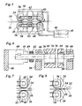
- FIG. 5 shows a first embodiment of the invention.
- the upper pressure rollers 24 and the lower pressure rollers 26 are each rotatably mounted on roller axles 54 (FIG. 6), which are each mounted in bearing plates 58 via eccentrically arranged drive axles 56.
- the pressure rollers 24 and 26 are pivotable about the respective drive axle 56.
- the drive of the drive shafts 56 via servo motors 60.
- the drive axles 56 of the upper pressure rollers 24 and the lower pressure rollers 26 are each force-coupled via toothed belt 62 and are driven by a servo motor 60. Instead of the toothed belt 62, the power coupling of the pressure rollers 24 and 26, for example, via gear stages.
- control devices 43 of the servomotors 60 are provided with control electronics 44 and positioners 45 recognizing the positions of the servomotors 60 (FIG. 6).
- Figure 6 shows a cross section through a lower pressure roller 26 and the associated servomotor 60 of Figure 5, corresponding to the plane indicated in Figure 5.
- the pressure roller 26 is rotatably mounted with fitted bearings 64 on the roller shaft 54. At the ends of the roller shaft 54 each eccentric portion of the drive axle 56 is fixed. Alternatively, the roller shaft 54 and the drive shaft 56 may be made in one piece.
- the drive shaft 56 is rotatably mounted in bearings 66 in the bearing plates 58.
- the servomotor 60 which is held on a plate 68, not shown in Figure 5, drives the drive shaft 56 at. On the servo motor 60, the position sensor 45 is arranged.
- roller shaft 54 By means of a rotational movement of the drive axle 56, the roller shaft 54 is pivoted about the drive axis 56.
- the rotatably mounted on the roller shaft 54 lower pressure roller 26 can be made so against the opposite upper pressure roller 24.
- a gear 69 is fixed, in which the toothed belt 62 engages, with which the force of the servo motor 60 is transmitted to the other drive axles 56 of the lower pressure rollers 26.
- the arrangement of the elements described on the roll axes 54 and drive axles 56 is only an example.
- Figure 7 shows a detail of Figure 5 with the right two pinch rollers 24 and 26. Shown are the drive axles 56, the servomotors 60, the timing belt 62 and the bearing plates 58. While the drive shafts 56 stand still, the pinch rollers 24 and 26 through the conveyor belts 14 and 16 taken and rotate about their roll axes 54 ( Figure 6). However, the distance between a pressure roller 24 or 26 and the passing thereon conveyor belt 14 and 16 may also be so large that the pressure roller is not moved.
- Figure 8 shows the same view as Figure 7, but in which the pressure rollers 24 and 26 are in the position employed on the conveyor belts 14 and 16 position.
- the pressure rollers 24 and 26 were pivoted to opposite directions by means of opposite rotational movements of the respective drive axes 56 of the transport direction 32 of the web 18 opposite.
- the distance between the drive axles 56 is so small that the pressure rollers 24 and 26 before their maximum vertical deflection against each other, so that the drive axles 56 can not perform a complete revolution. Therefore, the shutdown of a pressure roller 24 or 26 by means of the reversal of the direction of rotation of the motor 60 takes place.
- the fixed roller axes 54 may be adjustable.
- all drive axles 56 can also be coupled by a toothed belt or gear stages and can be driven by a single servomotor 60.
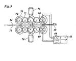
- Figure 9 shows a second embodiment with pressure elements 70 with engageable roller segments, which are coupled on both sides of the material web 18 respectively via gears 72 and rotatably mounted on a frame 74.
- the pressure elements 70 are driven by the motors 60 in a direction of rotation represented by an arrow.
- FIG. 9 shows the moment in which the roller segments of the pressure elements 70 are set against one another and engage with the conveyor belts 14 and 16 and the material web 18. They then continue to rotate in the salaried state and transport the severed portion of the web 18 while being further driven or free to be in line with the conveyor belts 14 and 16.
- the salaried state of the pressure elements ends 70 after a rotation of about 180 °.
- the control means 43 of the motors 60 the time of the next setting operation is controllable.
- the racks 74 are vertically displaceable by means of second motors 76. In this way, the contact pressure of the employed pressure elements 70 can be varied and made an adaptation to different thickness web materials.
- Such a displaceable mounting of the pressure elements 70 can also be advantageously used in the embodiment shown in Figure 5.
- the pressure elements 70 it is also possible for only the pressure elements 70 to have roll segments that can be set on one side of the material web 18 or to be mounted on a displaceable frame.
- the control means 43 of the motors 60 allow programmable adaptability of operating parameters, e.g. the displacement of the motors or the timing of the on and off movements in relation to the transport of the material web 18.
- operating parameters e.g. the displacement of the motors or the timing of the on and off movements in relation to the transport of the material web 18.
- the control means 43 can cooperate, is the tear-off device according to the invention particularly adaptable to various parameters of the material web 18 to be processed. Examples of this are different formats of the sections of the material web, different thickness material webs, different types of paper or other types of material of the web and different transport speeds.
- the preferred work and / or the tear-off each have their own drive the conveyor belts on a first and on a second side of the web.
- the axes of pressure elements facing one another on both sides of the material web are each vertical to one another arranged.
- the invention also includes such arrangements in which the pressure elements are arranged on both sides of the material web in the transport direction displaced relative to each other, so that the material web runs undressed when employed pressure elements through the tear-off.
Landscapes
- Auxiliary Devices For And Details Of Packaging Control (AREA)
- Perforating, Stamping-Out Or Severing By Means Other Than Cutting (AREA)
Claims (11)
- Dispositif de rupture pour des segments (46) d'une bande de matériau (18) avec un mécanisme de tirage (10) pour le transport de la bande de matériau (18) et avec un mécanisme de rupture (12), qui présente au moins deux éléments de pression (24; 26; 70) disposés sur les côtés opposés de la bande de matériau (18), desquels au moins l'un peut être ajustable sur la bande de matériau (18) par l'intermédiaire d'un dispositif de réglage, où le dispositif de réglage présente au moins un moteur (60) et un dispositif de commande (43) pourvu pour la commande temporisée du moteur (60) avec lequel élément de pression (24; 26; 70) peut être réglé à un moment contrôlable, caractérisé en ce que, chacun d'entre les éléments de pression (24; 26; 70) ajustables présente des segments cylindriques ou excentriques (54) montés en paliers avec la possibilité de rotation et qui peuvent être entraînés en rotation individuellement ou ensemble par les moteurs (60) ou le moteur (60) du dispositif de réglage, où avec le dispositif de commande (43) par un mouvement de rotation du segment cylindrique ou de l'excentrique (54), l'élément de pression (24; 26; 70) peut être réglé à un moment contrôlable.
- Dispositif de rupture selon la revendication 1, caractérisé en ce que, le moteur (60) est un servomoteur.
- Dispositif de rupture selon l'une des revendications antérieures, caractérisé en ce que, le mécanisme de tirage (10) et le mécanisme de rupture (12) présentent à raison d'un système d'entraînement propre (22).
- Dispositif de rupture selon l'une des revendications antérieures, caractérisé en ce que, le dispositif de commande (43) est un dispositif de commande programmable, avec lequel on peut fixer les moments des mouvements de couplage et/ou découplage par rapport au transport de la bande de matériau (18).
- Dispositif de rupture selon l'une des revendications 1 à 4, caractérisé en ce que, les éléments de pression (24; 26) qui peuvent être réglés sont des cylindres de pression, chacun étant monté en paliers avec la possibilité de rotation sur un excentrique (54), et que les excentriques (54) peuvent être entraînés en rotation individuellement ou ensemble par les moteurs (60) ou le moteur (60) du dispositif de réglage.
- Dispositif de rupture selon l'une des revendications 1 à 4, caractérisé en ce que, les éléments de pression (70) qui peuvent être réglés présentent chacun des segments cylindriques montés en paliers avec la possibilité de rotation et qui peuvent être entraînés en rotation individuellement ou ensemble par les moteurs (60) ou le moteur (60) du dispositif de couplage.
- Dispositif de rupture selon l'une des revendications antérieures, caractérisé en ce qu'au moins l'un d'entre les éléments de pression (24; 26; 70) est monté en paliers de sorte que celui, par l'intermédiaire au moins d'un second moteur (76) puisse être déplacé en essence perpendiculaire à l'égard de la bande de matériau (18).
- Dispositif de rupture selon l'une des revendications antérieures, caractérisé en ce que, cet au moins un moteur (60) du dispositif de couplage peut être entraîné en sens opposés sur un intervalle de réglage limité, et les mouvements de réglage du moteur (60) peuvent être commandés de manière temporisée par l'intermédiaire dispositif de commande (43).
- Dispositif de rupture selon les revendications 4 et 8, caractérisé en ce que, l'intervalle de réglage du moteur (60) est programmable.
- Dispositif de rupture selon l'une des revendications antérieures, caractérisé en ce que, cet au moins un moteur (60) peut être entraîné en rotation avec une vitesse variable dans un sens de rotation.
- Dispositif de rupture selon la revendication 10, caractérisé en ce que, la vitesse du moteur (60) peut être variée jusqu'à l'arrêt.
Priority Applications (4)
| Application Number | Priority Date | Filing Date | Title |
|---|---|---|---|
| DE50303941T DE50303941D1 (de) | 2003-04-16 | 2003-04-16 | Abreisseinrichtung für Materialbahnen |
| EP03008665A EP1468949B1 (fr) | 2003-04-16 | 2003-04-16 | Dispositif de rupture pour des matériaux en bande |
| ES03008665T ES2263870T3 (es) | 2003-04-16 | 2003-04-16 | Dispositivo de rotura para bandas de material. |
| US10/820,350 US20040206468A1 (en) | 2003-04-16 | 2004-04-08 | Tear-off device for continuous materials |
Applications Claiming Priority (1)
| Application Number | Priority Date | Filing Date | Title |
|---|---|---|---|
| EP03008665A EP1468949B1 (fr) | 2003-04-16 | 2003-04-16 | Dispositif de rupture pour des matériaux en bande |
Publications (2)
| Publication Number | Publication Date |
|---|---|
| EP1468949A1 EP1468949A1 (fr) | 2004-10-20 |
| EP1468949B1 true EP1468949B1 (fr) | 2006-06-21 |
Family
ID=32892887
Family Applications (1)
| Application Number | Title | Priority Date | Filing Date |
|---|---|---|---|
| EP03008665A Expired - Lifetime EP1468949B1 (fr) | 2003-04-16 | 2003-04-16 | Dispositif de rupture pour des matériaux en bande |
Country Status (4)
| Country | Link |
|---|---|
| US (1) | US20040206468A1 (fr) |
| EP (1) | EP1468949B1 (fr) |
| DE (1) | DE50303941D1 (fr) |
| ES (1) | ES2263870T3 (fr) |
Families Citing this family (1)
| Publication number | Priority date | Publication date | Assignee | Title |
|---|---|---|---|---|
| DE102008006562A1 (de) * | 2008-01-29 | 2009-10-15 | Böwe Systec AG | Verfahren und Vorrichtung zum Transport von Papier in einer Papierhandhabungsanlage von einem ersten Transport an einen zweiten Transport |
Family Cites Families (6)
| Publication number | Priority date | Publication date | Assignee | Title |
|---|---|---|---|---|
| US2911132A (en) * | 1956-11-06 | 1959-11-03 | Strachan & Henshaw Ltd | Web severing devices in web feeding machines |
| DE1231100B (de) * | 1964-12-01 | 1966-12-22 | Eberhard Tilger Dipl Ing | Anordnung zur Betaetigung der Trennvorrichtung zum Trennen von mit Schwaechungslinien versehenen Bahnen aus Papier, Kunststoff od. dgl. in einer Schlauchziehmaschine |
| US4131272A (en) * | 1977-06-13 | 1978-12-26 | Paper Converting Machine Company | Method and apparatus for separating a continuous stream of connected business forms into exact count zig-zag folded stacks |
| GB2249543B (en) * | 1990-11-09 | 1995-05-17 | Fmc Corp | Separator/folder bag machine |
| DE4440660C2 (de) * | 1994-11-14 | 1998-12-03 | Windmoeller & Hoelscher | Trenneinrichtung zum Abtrennen perforierter Schlauchabschnitte |
| EP0716036A1 (fr) * | 1994-12-09 | 1996-06-12 | Industria Grafica Meschi S.r.l. | Méthode pour rompre du papier imprimé delivré sous forme d'une bande continue dépourvue de perforations latérales d'entraînement et appareil de rupture et de pliage correspondant |
-
2003
- 2003-04-16 ES ES03008665T patent/ES2263870T3/es not_active Expired - Lifetime
- 2003-04-16 DE DE50303941T patent/DE50303941D1/de not_active Expired - Lifetime
- 2003-04-16 EP EP03008665A patent/EP1468949B1/fr not_active Expired - Lifetime
-
2004
- 2004-04-08 US US10/820,350 patent/US20040206468A1/en not_active Abandoned
Also Published As
| Publication number | Publication date |
|---|---|
| DE50303941D1 (de) | 2006-08-03 |
| US20040206468A1 (en) | 2004-10-21 |
| ES2263870T3 (es) | 2006-12-16 |
| EP1468949A1 (fr) | 2004-10-20 |
Similar Documents
| Publication | Publication Date | Title |
|---|---|---|
| DE4136792C2 (de) | Verstelleinrichtung für falzproduktführende Zylinder in Falzapparaten an Rotationsdruckmaschinen | |
| DE3836214C2 (fr) | ||
| EP0365573A1 (fr) | Machine d'etiquetage. | |
| EP3603948B1 (fr) | Installation de fabrication de carton ondulé | |
| DE2140088A1 (de) | Antriebssystem fur eine Bahnver arbeitungsvorrichtung | |
| CH696035A5 (de) | Vorrichtung zum registergenauen Ausrichten von Produkten aus Bogenmaterial in einer Vorrichtung zur Handhabung von Produkten aus Bogenmaterial. | |
| EP0365812B1 (fr) | Dispositif pour alimenter un dispositif de pliage en ébauches d'emballage | |
| WO2001087601A2 (fr) | Appareil de pliage | |
| EP1471023B1 (fr) | Dispositif de rupture pour des matériaux en bande | |
| DD282438A5 (de) | Vorrichtung zum zufuehren von bogen an eine bogenverarbeitende maschine, insbesondere druckmaschine | |
| EP1468949B1 (fr) | Dispositif de rupture pour des matériaux en bande | |
| EP1110887A1 (fr) | Dispositif pour guider des feuilles et procédé appliquant ledit dispositif de guidage | |
| CH696538A5 (de) | Signaturenübergabevorrichtung. | |
| EP0023985B1 (fr) | Dispositif de brochage pour machines d'impression | |
| EP0586926A2 (fr) | Dispositif pour couper et agrafer des produits imprimés à plusieurs couches dans des appareils de pliage | |
| CH696031A5 (de) | Vorrichtung zum Schneiden von Produkten aus Bogenmaterial. | |
| DE2112807C3 (de) | Vorrichtung zum Bedrucken bzw. Formstanzen von direkt aufeinanderfolgenden Abschnitten einer Materialbahn | |
| EP0870714B1 (fr) | Plieuse à lame, méthode pour le pliage transversal avec une plieuse à lame et ligne pour travaux de ville avec une plieuse à lame | |
| EP1870179A2 (fr) | Dispositif pour l' avancement cadencé d'une bande de matière | |
| DE19908118B4 (de) | Schneidmesserzylinder | |
| EP1972587A1 (fr) | Dispositif destiné à collecter des produits imprimés sur un cylindre de collecte | |
| EP1842606A1 (fr) | Dispositif pour le cintrage en forme de boucles d'un fil continu | |
| EP0829441B1 (fr) | Dispositif pour éjecter des feuilles imprimées et empilées | |
| EP1827870A2 (fr) | Plieuse a poches | |
| EP1525976B1 (fr) | Dispositif de fermeture de fonds dans une machine pour la fabrication de sacs |
Legal Events
| Date | Code | Title | Description |
|---|---|---|---|
| PUAI | Public reference made under article 153(3) epc to a published international application that has entered the european phase |
Free format text: ORIGINAL CODE: 0009012 |
|
| AK | Designated contracting states |
Kind code of ref document: A1 Designated state(s): AT BE BG CH CY CZ DE DK EE ES FI FR GB GR HU IE IT LI LU MC NL PT RO SE SI SK TR |
|
| AX | Request for extension of the european patent |
Extension state: AL LT LV MK |
|
| 17P | Request for examination filed |
Effective date: 20041117 |
|
| RAP1 | Party data changed (applicant data changed or rights of an application transferred) |
Owner name: NEWLONG INDUSTRIAL CO., LTD. |
|
| GRAP | Despatch of communication of intention to grant a patent |
Free format text: ORIGINAL CODE: EPIDOSNIGR1 |
|
| AKX | Designation fees paid |
Designated state(s): DE DK ES GB IT |
|
| GRAS | Grant fee paid |
Free format text: ORIGINAL CODE: EPIDOSNIGR3 |
|
| GRAA | (expected) grant |
Free format text: ORIGINAL CODE: 0009210 |
|
| AK | Designated contracting states |
Kind code of ref document: B1 Designated state(s): DE DK ES GB IT |
|
| PG25 | Lapsed in a contracting state [announced via postgrant information from national office to epo] |
Ref country code: IT Free format text: LAPSE BECAUSE OF FAILURE TO SUBMIT A TRANSLATION OF THE DESCRIPTION OR TO PAY THE FEE WITHIN THE PRESCRIBED TIME-LIMIT;WARNING: LAPSES OF ITALIAN PATENTS WITH EFFECTIVE DATE BEFORE 2007 MAY HAVE OCCURRED AT ANY TIME BEFORE 2007. THE CORRECT EFFECTIVE DATE MAY BE DIFFERENT FROM THE ONE RECORDED. Effective date: 20060621 Ref country code: GB Free format text: LAPSE BECAUSE OF FAILURE TO SUBMIT A TRANSLATION OF THE DESCRIPTION OR TO PAY THE FEE WITHIN THE PRESCRIBED TIME-LIMIT Effective date: 20060621 |
|
| REG | Reference to a national code |
Ref country code: GB Ref legal event code: FG4D Free format text: NOT ENGLISH |
|
| REF | Corresponds to: |
Ref document number: 50303941 Country of ref document: DE Date of ref document: 20060803 Kind code of ref document: P |
|
| PG25 | Lapsed in a contracting state [announced via postgrant information from national office to epo] |
Ref country code: DK Free format text: LAPSE BECAUSE OF FAILURE TO SUBMIT A TRANSLATION OF THE DESCRIPTION OR TO PAY THE FEE WITHIN THE PRESCRIBED TIME-LIMIT Effective date: 20060921 |
|
| REG | Reference to a national code |
Ref country code: ES Ref legal event code: FG2A Ref document number: 2263870 Country of ref document: ES Kind code of ref document: T3 |
|
| GBV | Gb: ep patent (uk) treated as always having been void in accordance with gb section 77(7)/1977 [no translation filed] |
Effective date: 20060621 |
|
| PLBE | No opposition filed within time limit |
Free format text: ORIGINAL CODE: 0009261 |
|
| STAA | Information on the status of an ep patent application or granted ep patent |
Free format text: STATUS: NO OPPOSITION FILED WITHIN TIME LIMIT |
|
| 26N | No opposition filed |
Effective date: 20070322 |
|
| PGFP | Annual fee paid to national office [announced via postgrant information from national office to epo] |
Ref country code: ES Payment date: 20080424 Year of fee payment: 6 |
|
| PGRI | Patent reinstated in contracting state [announced from national office to epo] |
Ref country code: IT Effective date: 20081001 |
|
| PGFP | Annual fee paid to national office [announced via postgrant information from national office to epo] |
Ref country code: IT Payment date: 20090428 Year of fee payment: 7 |
|
| REG | Reference to a national code |
Ref country code: ES Ref legal event code: FD2A Effective date: 20090417 |
|
| PG25 | Lapsed in a contracting state [announced via postgrant information from national office to epo] |
Ref country code: ES Free format text: LAPSE BECAUSE OF NON-PAYMENT OF DUE FEES Effective date: 20090417 |
|
| PG25 | Lapsed in a contracting state [announced via postgrant information from national office to epo] |
Ref country code: IT Free format text: LAPSE BECAUSE OF NON-PAYMENT OF DUE FEES Effective date: 20100416 |
|
| PGFP | Annual fee paid to national office [announced via postgrant information from national office to epo] |
Ref country code: DE Payment date: 20110530 Year of fee payment: 9 |
|
| REG | Reference to a national code |
Ref country code: DE Ref legal event code: R119 Ref document number: 50303941 Country of ref document: DE Effective date: 20121101 |
|
| PG25 | Lapsed in a contracting state [announced via postgrant information from national office to epo] |
Ref country code: DE Free format text: LAPSE BECAUSE OF NON-PAYMENT OF DUE FEES Effective date: 20121101 |