EP1468345B1 - System und verfahren zur koordinierten steuerung eines geschalteten leistungskondensators mit integriertem resonanzschutzsystem - Google Patents
System und verfahren zur koordinierten steuerung eines geschalteten leistungskondensators mit integriertem resonanzschutzsystem Download PDFInfo
- Publication number
- EP1468345B1 EP1468345B1 EP20020806214 EP02806214A EP1468345B1 EP 1468345 B1 EP1468345 B1 EP 1468345B1 EP 20020806214 EP20020806214 EP 20020806214 EP 02806214 A EP02806214 A EP 02806214A EP 1468345 B1 EP1468345 B1 EP 1468345B1
- Authority
- EP
- European Patent Office
- Prior art keywords
- control parameters
- resonance
- capacitor
- determining
- condition
- Prior art date
- Legal status (The legal status is an assumption and is not a legal conclusion. Google has not performed a legal analysis and makes no representation as to the accuracy of the status listed.)
- Expired - Lifetime
Links
Images


Classifications
-
- G—PHYSICS
- G05—CONTROLLING; REGULATING
- G05F—SYSTEMS FOR REGULATING ELECTRIC OR MAGNETIC VARIABLES
- G05F1/00—Automatic systems in which deviations of an electric quantity from one or more predetermined values are detected at the output of the system and fed back to a device within the system to restore the detected quantity to its predetermined value or values, i.e. retroactive systems
-
- H—ELECTRICITY
- H02—GENERATION; CONVERSION OR DISTRIBUTION OF ELECTRIC POWER
- H02M—APPARATUS FOR CONVERSION BETWEEN AC AND AC, BETWEEN AC AND DC, OR BETWEEN DC AND DC, AND FOR USE WITH MAINS OR SIMILAR POWER SUPPLY SYSTEMS; CONVERSION OF DC OR AC INPUT POWER INTO SURGE OUTPUT POWER; CONTROL OR REGULATION THEREOF
- H02M1/00—Details of apparatus for conversion
- H02M1/12—Arrangements for reducing harmonics from AC input or output
-
- H—ELECTRICITY
- H02—GENERATION; CONVERSION OR DISTRIBUTION OF ELECTRIC POWER
- H02J—ELECTRIC POWER NETWORKS; CIRCUIT ARRANGEMENTS OR SYSTEMS FOR SUPPLYING OR DISTRIBUTING ELECTRIC POWER; SYSTEMS FOR STORING ELECTRIC ENERGY
- H02J3/00—Circuit arrangements for AC mains or AC distribution networks
- H02J3/001—Arrangements for handling faults or abnormalities, e.g. emergencies or contingencies
- H02J3/0014—Arrangements for handling faults or abnormalities, e.g. emergencies or contingencies for preventing or reducing power oscillations in networks
-
- H—ELECTRICITY
- H02—GENERATION; CONVERSION OR DISTRIBUTION OF ELECTRIC POWER
- H02J—ELECTRIC POWER NETWORKS; CIRCUIT ARRANGEMENTS OR SYSTEMS FOR SUPPLYING OR DISTRIBUTING ELECTRIC POWER; SYSTEMS FOR STORING ELECTRIC ENERGY
- H02J3/00—Circuit arrangements for AC mains or AC distribution networks
- H02J3/18—Arrangements for adjusting, eliminating or compensating reactive power in networks
Definitions
- the present invention relates to systems and methods for coordinated control of a switched power capacitor with an integrated resonance protection system. More specifically, the invention relates to adjusting calculations made by the primary control system in response to a determination of a harmonic resonance condition by the resonance protection system.
- Existing switched power capacitor control systems may include a primary control system and a harmonic resonance protection system.
- the primary control system determines if a capacitor switching operation is needed by comparing actual control parameters to target control parameters and determining if a switching operation would make the actual control parameters closer in value to the target control parameters.
- Target control parameters are predetermined.
- Actual control parameters are calculated by the primary control system based on measurements of voltages and currents obtained with voltage and current transformers respectively: If a switching operation is required, the primary control system further determines which capacitor bank is to be switched based on other factors such as, for example, a capacitor's size and whether a capacitor is connected or disconnected.
- the resonance protection system monitors the circuit for harmonic resonance conditions.
- Harmonic resonance conditions may be due to capacitor switching operations or system changes such as, for example, a load change, a system source impedance change, or a network topology change. Harmonic resonance may cause significant harmonic distortion in the system voltages and currents, which may increase the losses in the circuit and cause damage to equipment operating in the system due to overheating and vibration.
- the protection system performs additional capacitor switching operation to de-tune the circuit from the sustained resonance. If a switching operation is required, the harmonic resonance protection system further determines which capacitor is to be switched based on other factors such as, for example, a capacitor's size and whether a capacitor is connected or disconnected.
- Existing switched power capacitor control systems may contain both an independent primary control system and an independent resonance protection system.
- the independence of these two systems results in several drawbacks.
- the independent systems must duplicate certain functions such as, for example, determining whether a capacitor is connected and generating a signal to control a capacitor.
- the independent systems may, under certain circumstances, force the capacitor banks into a constant on/off operation deadlock. For example, the primary control system may determine that a certain capacitor bank needs to be switched on.
- the resonance protection system will perform additional capacitor switching operations to de-tune the circuit from the sustained resonance. It is possible that the resonance protection system may determine to switch off the same capacitor bank that the primary control system switched on. Once the capacitor bank is switched off by the resonance protection system, the primary control system will switch the capacitor bank back on. This operation deadlock can cause excessive wear to the capacitors and the switching apparatus. Thus, it would be a great improvement in the art to integrate and coordinate the primary control system and the resonance protection system to avoid duplication of functions and switching deadlock.
- US Patent 5548203 discloses a method for coordinated control of a switched power capacitor with an integrated resonance protection function, comprising the steps of :
- the present invention is a method and a system as defined in Claims 1 and 9.
- FIG. 1 illustrates a switched power capacitor device 120 in accordance with an aspect of the present invention.
- feeder 110 feeds switched power capacitor device 120 that includes breaker switched capacitor banks 140a and 140b along with control unit 160.
- Control unit 160 measures voltage 180 and current 190 to determine switching operations for capacitor banks 140a and 140b that provide the desired power to load 170.
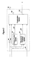
- Figure 2 illustrates a block diagram of the control unit 160 of the switched power capacitor device 120 in accordance with the present invention.
- primary control system 220 calculates control parameters.
- Resonance protection system 230 determines if a harmonic resonance condition is present
- Coordination system 240 adjusts the control parameters if a harmonic resonance condition is present and performs capacitor switching operations based on the control parameters.
- primary control system 220 transmits control parameters 222 to coordination system 240.
- Control parameters 222 comprise any parameter relevant to the control of a switched power capacitor, such as, for example, power factor and node voltage.
- Control parameters 222 consist of both pre-determined target parameters and actual parameters calculated by primary control system 220.
- Control parameters 222 may also consist of the difference between target parameters and actual parameters.
- Primary control system calculates actual parameters based on measurements of voltage 180 and current 190 obtained with voltage and current transformers respectively.
- Resonance protection system 230 determines if a harmonic resonance condition is present and transmits an input 232 to coordination system 240 indicating whether a harmonic resonance condition had been detected. Exemplary methods for determining if a harmonic resonance condition is present are described in detail in U.S. Pat. No. 6,181,113 . If input 232 indicates that a harmonic resonance condition is present, then coordination system 240 adjusts control parameters 222. Coordination system 240 adjusts control parameters 222 to de-tune switched power capacitor 120 from a harmonic resonance condition. Coordination system 240 may adjust control parameters 222 by any method such as, for example, reducing the target reactive power by the value of the reactive power provided by one capacitor bank.
- Coordination system 240 performs capacitor bank switching operations 244 based on control parameters 222. Coordination system 240 compares actual control parameters to target control parameters, and determines if a switching operation is necessary to make the value of the actual parameters closer to the value of the target parameters. Coordination system 240 further determines whether a switching operation is needed based on other factors such as, for example, the operating status 242 of each capacitor bank and the size of each capacitor. Determining the operating status 242 of each capacitor comprises determining whether the capacitor is connected or disconnected.
- FIG. 3 illustrates a flow chart of an illustrative method for controlling a switched power capacitor in accordance with the present invention.
- coordination system 240 clears resonance flags.
- coordination system 240 receives control parameters 222 from primary control system 220.
- Control parameters 222 comprise any parameters relevant to the control of a switched power capacitor, such as, for example, power factor and node voltage.
- coordination system 240 determines if a resonance flag is set.
- coordination system 240 determines whether input 232 indicates that a harmonic resonance condition is present. If a harmonic resonance condition is present, then, at step 318, coordination system 240 sets a resonance flag and adjusts control parameters 222. Coordination system 240 may adjust control parameters 222 by any method such as, for example, reducing the target reactive power by the value of the reactive power provided by one capacitor bank.
- Coordination system 240 adjusts control parameters 222.
- the adjustment made at step 320 will be equivalent to the adjustment made at step 318 to avoid performing multiple switching operations prior to the reset of a resonance flag.
- coordination system 240 determines if resonance flag reset conditions have been satisfies.
- a resonance flag reset condition may be triggered by the expiration of a pre-set time delay or by a system condition change that exceeds a preset threshold value.
- a system conditions change may include events such as, for example, a load change, a system source impedance change, or a network topology change. Such events may de-tune the circuit from a resonance condition. If a resonance flag reset condition has been satisfied, then, at step 324, coordination system 240 resets the resonance flag.
- coordination system 240 determines if a capacitor bank switching operation 244 is needed. To determine if a capacitor switching operation is needed, coordination system 240 compares actual control parameters to target control parameters, and determines if a switching operation is necessary to make the value of the actual parameters closer to the value of the target parameters. Coordination system 240 further determines whether a switching operation is needed based on other factors such as, for example, the operating status 242 of each capacitor bank and the size of each capacitor. Deters the operating status 242 of each capacitor comprises determining whether the capacitor is connected or disconnected. If a capacitor bank switching operation 244 is needed, then, at step 328, coordination system 240 performs capacitor bank switching operations 244. The method then return to step 312.
Landscapes
- Engineering & Computer Science (AREA)
- Power Engineering (AREA)
- Physics & Mathematics (AREA)
- Electromagnetism (AREA)
- General Physics & Mathematics (AREA)
- Radar, Positioning & Navigation (AREA)
- Automation & Control Theory (AREA)
- Supply And Distribution Of Alternating Current (AREA)
- Control Of Electrical Variables (AREA)
- Emergency Protection Circuit Devices (AREA)
Claims (16)
- Verfahren zur koordinierten Steuerung eines geschalteten Leistungskondensators mit einer integrierten Resonanzschutzfunktion, die folgenden Schritte umfassend:A. Empfangen von Steuerungsparametern (312) und einer Anzeige darüber, ob ein harmonischer Resonanzzustand vorliegt (314), wobei die Steuerungsparameter eine Zielblindleistung des geschalteten Leistungskondensators enthalten;B. wenn ein harmonischer Resonanzzustand vorliegt, dann Anpassen der Steuerungsparameter (320) durch Reduzieren der Zielblindleistung um die Blindleistung mindestens einer Kondensatorbank, wobei der Schritt des Anpassens von Steuerungsparatnetern weiter enthält zu bestimmen, ob eine Resonanzkennzeichnung gesetzt ist; wenn eine Resonanzkennzeichnung nicht gesetzt ist, danna. Bestimmen, ob ein Resonanzzustand vorliegt (316),b. wenn ein ltesvnanzzustand vorliegt, dann Anpassen von Steuerungsparametern und Setzen einer Resonanzkennzeichnung (318),wenn eine Resonanzkennzeichnung gesetzt ist, danna. Anpassen von Steuerungsparametern (320),b. Bestimmen, ob ein Resonanzkennzeicbzxungs-Rücksetzungszustand vorliegt, durch Bestimmen, ob mindestens eine einer im Voraus bestimmten Zeitverzögerungen abgelaufen ist oder ein Überschreiten eines im Voraus bestimmten Schwellenwerts durch eine Systemzustandsänderung vorgekommen ist (322), undc. wenn ein Resonanzkennzeichnungs-Rücksetzungszustand vorliegt dann Rücksetzen der Resonanzkennzeichnung (324), undC. Durchführen von Kondensatorschaltoperationen basierend auf den Steuerungsparametern und Zurückkehren zu Schritt A.
- Verfahren nach Anspruch 1, wobei der Schritt des Empfangenes von Steuerungsparametern umfasst, Zielsteuerungsparameter und Iststeuerungsparameter zu empfangen.
- Verfahren nach Anspruch 1, wobei der Schritt des Empfangenes von Steuerungsparametern umfasst, mindestens eines des Leistungsfaktors und der Knotenspannung zu empfangen.
- Verfahren nach Anspruch 1, wobei der Schritt des Bestimmens, ob ein Überschreiten eines im Voraus bestimmten Schwellenwerts durch eine Systemzustandsänderung vorgenommen ist, umfasst zu bestimmen, ob mindestens eines eines Überschreitens eines im Voraus bestimmten Schwellenwerts durch eine Laständerung, eine Systemquellenimpedanzänderung und eine Netztopologieänderung vorgekommen ist.
- Verfahren nach Anspruch 1, wobei der Schritt des Anpassens der Steuerungsparameter umfasst, die Blindleistung um die durch eine Kondensatorbank bereitgestellte Blindleistung zu reduzieren.
- Verfahren nach Anspruch 1, wobei der Schritt des Durchführens von Kondenstorschaltoperationen die folgenden Schritte umfasst: Bestimmen, ob Kondensatorschaltoperationen benötigt werden (326), und wenn Kondcnsatorschaltoperationen benötigt werden, dann Durchführen von Kondensatozschaltvpezationen (328).
- Verfahren nach Anspruch 6, wobei der Schritt des Bestimmens, ob Kondensatorschaltoperationen benötigt werden, die folgenden Schritte umfasst: Vergleichen von Iststeuerungsparametern mit Zielsteuezungspazametern; und Bestimmen, ob eine Kondensatorschaltoperation Iststeuerungsparameter näher zu Zielsteuerungsparametern machen würde.
- Verfahren nach Anspruch 7, weiter umfassend mindestens eines von Bestimmen, ob jede Kondensatorbank verbunden oder nicht verbunden ist, und Bestimmen der Größte jedes Kondensators.
- System für koordinierte Steuerung eines geschalteten Leistungskottdensators mit einer integrierten Resonanzschutzfunktion, einen Steuerungsprozessor umfassend, der zum Durchführen des folgenden Prozesses programmiert ist:A. Empfangen von Steuerungsparametern (312) und einer Anzeige darüber, ob ein harmonische Resonanzzustand vorliegt (314), wobei die Steuerungsparameter eine Zielblindleistung des geschalteten Leistungskondensators enthalten;B. wenn ein harmonischer Resonanzzustand vorliegt, dann Anpassen der Steuerungsparameter (320) durch Reduzieren der Zielblindleistung um die Blindleistung mindestens einer Kondensatorbank, wobei der Schritt des Anpassens von Steuerungsparametern weiter enthält zu bestimmen, ob eine Resonanzkennzeichnung gesetzt ist; wenn eine Resonanzkennzeichnung nicht gesetzt ist, danna. Bestimmen, ob ein Resonanzzustand vorliegt (316),b. wenn ein ktesonanzzustand vorliegt, dann Anpassen von Steuerungsparametern und Setzen einer Resonanzkennzeichnung (318),wenn eine Resonanzkennzeichnung gesetzt ist, danna. Anpassen von Steuerungsparametern (320),b. Bestimmen, ob ein Resonanzkennzeichnungs-Rücksetzungszustand vorliegt, durch Bestimmen, ob mindestens eine einer im Voraus bestimmten Zeitverzögerungen abgelaufen ist oder ein Überschreiten eines im Voraus bestimmten Schwellenwerts durch eine Systemzustandsänderung vorgekommen ist (322), undc. wenn ein Resonanzkennzeichnungs-Rücksetzungszustand vorliegt, dann Rücksetzen der Resonanzkennzeichnung (324), undC. Durchführen von Kondensatorschaltoperationen basierend auf den Steuerungsparametern und Zurückkehren zu Schritt A.
- System nach Anspruch 9, wobei die Steuerungsparameter Zielsteuerungsparameter und Iststeuerungsparameter umfassend.
- System nach Anspruch 10, wobei die Steuerungsparameter mindestens eines des Lexsrimgsfalctors und der Knotenspannung umfassen.
- System nach Anspruch 9, wobei die Systemzustandsänderung mindestens eine einer Laständerung, einer Systenn:quolleninnpedanzänderung und einer Netztopologieänderung umfasst.
- System nach Anspruch 9, wobei Anpassen der Steuerungsparameter umfasst, die Blindleistung um die durch eine Kondensatorbanac bereitgestellte Blindleistung zu reduzieren.
- System nach Anspruch 9, wobei Durchführen von Kondensatorschaltoperationen umfasst: Bestimmen, ob Kondensatorschaltoperationen benötigt werden (326), und wenn Kondensatorschaltoperationen benötigt werden, dann Durchführen von Kondensatorschaltvperationen (328).
- System nach Anspruch 14, wobei Bestimmen, ob Kondensatorschaltoperationen benötigt werden, umfasst: Vergleichen von Iststeuerungsparametem mit Zielsteuerungsparametern; und Bestimmen, ob eine Kondensatorschaltoperation Iststeuerungsparameter näher zu Zielsteuerungsparametem machen würde.
- System nach Anspruch 15, weiter umfassend mindestens eines von Bestimmen, ob jede Kondensatorbank verbunden oder nicht verbunden ist, und Bestimmen der Größe jedes Kondensators.
Applications Claiming Priority (3)
| Application Number | Priority Date | Filing Date | Title |
|---|---|---|---|
| US34063 | 2001-12-26 | ||
| US10/034,063 US6747373B1 (en) | 2001-12-26 | 2001-12-26 | System and method for coordinated control of a switched power capacitor with an integrated resonance protection system |
| PCT/US2002/041297 WO2003058653A2 (en) | 2001-12-26 | 2002-12-20 | System and method for coordinated control of a switched power capacitor with an integrated resonance protection system |
Publications (3)
| Publication Number | Publication Date |
|---|---|
| EP1468345A2 EP1468345A2 (de) | 2004-10-20 |
| EP1468345A4 EP1468345A4 (de) | 2009-01-21 |
| EP1468345B1 true EP1468345B1 (de) | 2011-11-16 |
Family
ID=21874069
Family Applications (1)
| Application Number | Title | Priority Date | Filing Date |
|---|---|---|---|
| EP20020806214 Expired - Lifetime EP1468345B1 (de) | 2001-12-26 | 2002-12-20 | System und verfahren zur koordinierten steuerung eines geschalteten leistungskondensators mit integriertem resonanzschutzsystem |
Country Status (12)
| Country | Link |
|---|---|
| US (1) | US6747373B1 (de) |
| EP (1) | EP1468345B1 (de) |
| CN (1) | CN100397281C (de) |
| AT (1) | ATE534065T1 (de) |
| AU (1) | AU2002367369A1 (de) |
| BR (2) | BR0207589A (de) |
| ES (1) | ES2377699T3 (de) |
| FI (1) | FI20031193A7 (de) |
| NO (1) | NO331729B1 (de) |
| RU (1) | RU2300799C2 (de) |
| SE (1) | SE525393C2 (de) |
| WO (1) | WO2003058653A2 (de) |
Families Citing this family (8)
| Publication number | Priority date | Publication date | Assignee | Title |
|---|---|---|---|---|
| US7253481B2 (en) * | 2005-07-14 | 2007-08-07 | Taiwan Semiconductor Manufacturing Company, Ltd. | High performance MOS device with graded silicide |
| US7569896B2 (en) * | 2006-05-22 | 2009-08-04 | Taiwan Semiconductor Manufacturing Company, Ltd. | Transistors with stressed channels |
| US7364957B2 (en) * | 2006-07-20 | 2008-04-29 | Taiwan Semiconductor Manufacturing Company, Ltd. | Method and apparatus for semiconductor device with improved source/drain junctions |
| US20090310272A1 (en) * | 2008-06-17 | 2009-12-17 | Global Energy Savings, Inc. | Energy savings and surge protection device |
| US20100259230A1 (en) * | 2009-04-13 | 2010-10-14 | Boothroyd Howard G | Power factor correction device with adjustable capacitance |
| RU2561822C2 (ru) * | 2011-06-24 | 2015-09-10 | Закрытое акционерное общество "ГРИН ЭНЕРДЖИ" | Способ энергосбережения |
| DE102012216266A1 (de) * | 2012-09-13 | 2014-03-13 | Siemens Aktiengesellschaft | Verfahren und Vorrichtung zum Herstellen eines Filters und Filter |
| ES2539534B1 (es) * | 2014-10-03 | 2016-02-19 | Jaime MARTÍN ASENSIO | Sistema recuperador de energía |
Family Cites Families (31)
| Publication number | Priority date | Publication date | Assignee | Title |
|---|---|---|---|---|
| SU530328A1 (ru) * | 1974-07-01 | 1976-09-30 | Ленинградское Отделение Государственного Ордена Трудового Красного Знамени Проектного Института "Тяжпромэлектропроект" | Устройство дл управлени шунтовой конденсаторной батареей |
| US4891569A (en) | 1982-08-20 | 1990-01-02 | Versatex Industries | Power factor controller |
| SU1275409A1 (ru) * | 1985-04-08 | 1986-12-07 | Markushevich Nokhum S | Способ автоматического регулировани конденсаторных батарей энергосистемы |
| US4897775A (en) | 1986-06-16 | 1990-01-30 | Robert F. Frijouf | Control circuit for resonant converters |
| US4769587A (en) | 1987-03-09 | 1988-09-06 | Beckwith Electric Co. | Power factor control with overvoltage and undervoltage override control in a capacitor control system for a distribution system |
| SU1677706A1 (ru) * | 1988-07-05 | 1991-09-15 | В.М.Позин | Способ автоматического регулировани конденсаторной батареи |
| DE3905261A1 (de) | 1989-02-21 | 1990-08-23 | Siemens Ag | Verfahren und einrichtung zur stabilisation eines elektrischen versorgungsnetzes |
| US5224029A (en) * | 1991-08-16 | 1993-06-29 | Newman Jr Robert C | Power factor and harmonic correction circuit including ac startup circuit |
| US5424627A (en) * | 1991-12-13 | 1995-06-13 | Electric Power Research Institute | Modular thyristor controlled series capacitor control system |
| US5270914A (en) | 1992-01-10 | 1993-12-14 | Lauw Hian K | Series resonant converter control system and method |
| JPH05227795A (ja) * | 1992-02-10 | 1993-09-03 | Alex Denshi Kogyo Kk | 誘導電動機制御装置および制御方法 |
| US5212441A (en) * | 1992-02-25 | 1993-05-18 | Basic Measuring Instruments, Inc. | Harmonic-adjusted power factor meter |
| US5475291A (en) * | 1992-12-10 | 1995-12-12 | Matsushita Electric Industrial Co., Ltd. | Adjustment device for adjusting control parameters of a servo motor and an adjustment method therefor |
| FR2716045B1 (fr) * | 1994-02-04 | 1996-03-15 | Schlumberger Ind Sa | Filtre actif. |
| US5548203A (en) | 1994-06-29 | 1996-08-20 | Electric Power Research Institute, Inc. | Capacitor polarity-based var correction controller for resonant line conditions and large amplitude line harmonics |
| US5825162A (en) * | 1994-07-25 | 1998-10-20 | Hitachi, Ltd. | Electric power flow controller |
| JP2795183B2 (ja) | 1994-08-08 | 1998-09-10 | 松下電器産業株式会社 | 静止形無効電力補償装置 |
| US5600549A (en) * | 1994-09-20 | 1997-02-04 | Astec International, Ltd. | Power factor corrected electrical power converter |
| US5670864A (en) | 1995-05-26 | 1997-09-23 | Pacific Scientific Company | Adaptive automatic power capacitor for controlling controller a capacitor bank of a power distribution system |
| US5726504A (en) * | 1996-05-24 | 1998-03-10 | Pecukonis; Joseph P. | Apparatus and method for adaptively canceling harmonic currents in a power line |
| US5977660A (en) * | 1996-08-09 | 1999-11-02 | Mesta Electronics, Inc. | Active harmonic filter and power factor corrector |
| RO120431B1 (ro) * | 1996-10-22 | 2006-01-30 | Abb Power T & D Company Inc. | Dispozitiv electric de măsurare a energiei electrice |
| US6008548A (en) | 1997-09-19 | 1999-12-28 | Cinergy Corp. | Programmable logic controller for resonance control in complex capacitor switching |
| GB2336223B (en) | 1998-04-09 | 2000-04-19 | Alstom Uk Ltd | Improvements in or relating to the application of power-factor correction in AV power systems |
| US6075350A (en) * | 1998-04-24 | 2000-06-13 | Lockheed Martin Energy Research Corporation | Power line conditioner using cascade multilevel inverters for voltage regulation, reactive power correction, and harmonic filtering |
| US5963021A (en) * | 1998-05-11 | 1999-10-05 | Siemens Power Transmission & Distribution, Llc | Delayed contact closing apparatus and method for capacitors |
| US6157177A (en) | 1999-01-19 | 2000-12-05 | Infineon Technologies Ag | Switched mode power supply for supplying a main and an auxiliary electrical circuit |
| US6181113B1 (en) | 1999-07-29 | 2001-01-30 | Abb Power T&D Company Inc. | Harmonic resonance control and protection system for switched power factor control capacitor devices |
| US6166929A (en) * | 2000-02-29 | 2000-12-26 | Rockwell Technologies, Llc | CSI based drive having active damping control |
| US6177781B1 (en) * | 2000-05-25 | 2001-01-23 | Steve Yiua Shi Yin | Power-factor improvement device |
| DE60108099T2 (de) * | 2001-07-16 | 2005-06-02 | Axa Power A/S | Kompensation des Spannungsabfalls eines Kabels in einem elektrischen Energieversorgungssystem |
-
2001
- 2001-12-26 US US10/034,063 patent/US6747373B1/en not_active Expired - Lifetime
-
2002
- 2002-12-20 BR BR0207589A patent/BR0207589A/pt not_active IP Right Cessation
- 2002-12-20 BR BRPI0207589-0A patent/BRPI0207589B1/pt unknown
- 2002-12-20 EP EP20020806214 patent/EP1468345B1/de not_active Expired - Lifetime
- 2002-12-20 WO PCT/US2002/041297 patent/WO2003058653A2/en not_active Ceased
- 2002-12-20 FI FI20031193A patent/FI20031193A7/fi not_active Application Discontinuation
- 2002-12-20 AT AT02806214T patent/ATE534065T1/de active
- 2002-12-20 RU RU2004122927A patent/RU2300799C2/ru not_active IP Right Cessation
- 2002-12-20 AU AU2002367369A patent/AU2002367369A1/en not_active Abandoned
- 2002-12-20 ES ES02806214T patent/ES2377699T3/es not_active Expired - Lifetime
- 2002-12-20 CN CNB02827573XA patent/CN100397281C/zh not_active Expired - Lifetime
-
2003
- 2003-08-26 SE SE0302283A patent/SE525393C2/sv unknown
- 2003-08-26 NO NO20033787A patent/NO331729B1/no not_active IP Right Cessation
Also Published As
| Publication number | Publication date |
|---|---|
| WO2003058653A2 (en) | 2003-07-17 |
| SE0302283L (sv) | 2003-10-27 |
| WO2003058653A3 (en) | 2003-12-11 |
| NO20033787D0 (no) | 2003-08-26 |
| SE525393C2 (sv) | 2005-02-15 |
| SE0302283D0 (sv) | 2003-08-26 |
| FI20031193L (fi) | 2003-10-15 |
| CN100397281C (zh) | 2008-06-25 |
| EP1468345A4 (de) | 2009-01-21 |
| AU2002367369A1 (en) | 2003-07-24 |
| EP1468345A2 (de) | 2004-10-20 |
| RU2300799C2 (ru) | 2007-06-10 |
| CN1618051A (zh) | 2005-05-18 |
| ES2377699T3 (es) | 2012-03-30 |
| ATE534065T1 (de) | 2011-12-15 |
| BR0207589A (pt) | 2004-06-08 |
| BRPI0207589B1 (pt) | 2017-06-27 |
| RU2004122927A (ru) | 2006-01-20 |
| AU2002367369A8 (en) | 2003-07-24 |
| NO20033787L (no) | 2003-10-24 |
| FI20031193A7 (fi) | 2003-10-15 |
| NO331729B1 (no) | 2012-03-12 |
| US6747373B1 (en) | 2004-06-08 |
Similar Documents
| Publication | Publication Date | Title |
|---|---|---|
| US5726561A (en) | Voltage selection apparatus and methods | |
| US8412966B2 (en) | Voltage sensing circuitry for solid state power controllers | |
| EP0044181B1 (de) | Wechselstromleistungsversorgungssystem und Verfahren und Gerät zum Steuern seiner Last | |
| US20010017485A1 (en) | Control system and method for switching and intercepting power supplies | |
| EP1468345B1 (de) | System und verfahren zur koordinierten steuerung eines geschalteten leistungskondensators mit integriertem resonanzschutzsystem | |
| KR100464596B1 (ko) | 과부하 검출 회로 차단기 | |
| JP2001352678A (ja) | 電力系統安定化装置 | |
| AU583868B2 (en) | Power systems | |
| KR100710658B1 (ko) | 증강된 보호 기능을 가진 전력 분배 시스템의 자동화된 재배치 방법 및 장치 | |
| US4414598A (en) | Regulated power supply | |
| US4330686A (en) | Loudspeaker systems | |
| JPH0549169A (ja) | 電力制御装置 | |
| Henry et al. | Improvement of power quality by means of fault current limitation | |
| CN113839545B (zh) | 一种带抑制过冲电路的开关电源系统 | |
| AU2021288503B2 (en) | Method and device for monitoring a three-phase network operated in a compensated manner for a tuning change of the arc suppression coil | |
| JP3227653B2 (ja) | 電力系統保護制御装置 | |
| JP2003513603A (ja) | スタチック形調整器 | |
| KR100256910B1 (ko) | 전원절체 및 단속제어장치 | |
| JP3761630B2 (ja) | 自動力率調整装置 | |
| CN214543618U (zh) | 配网消弧不间断电源电路及消弧系统 | |
| US7058672B2 (en) | Resonant protection kit for power supply | |
| JPH0382337A (ja) | 系統安定化装置 | |
| EP4651341A1 (de) | Verfahren und system zur gewinnung elektromagnetischer induktionsenergie mit adaptiver steuerung für einen übertragungsleiter | |
| JPH0746837A (ja) | スイッチング電源装置 | |
| CN119560975A (zh) | 基于电压波形的实时监控方法及监控电路 |
Legal Events
| Date | Code | Title | Description |
|---|---|---|---|
| PUAI | Public reference made under article 153(3) epc to a published international application that has entered the european phase |
Free format text: ORIGINAL CODE: 0009012 |
|
| 17P | Request for examination filed |
Effective date: 20040702 |
|
| AK | Designated contracting states |
Kind code of ref document: A2 Designated state(s): AT BE BG CH CY CZ DE DK EE ES FI FR GB GR IE IT LI LU MC NL PT SE SI SK TR |
|
| AX | Request for extension of the european patent |
Extension state: AL LT LV MK RO |
|
| A4 | Supplementary search report drawn up and despatched |
Effective date: 20081219 |
|
| 17Q | First examination report despatched |
Effective date: 20090624 |
|
| GRAP | Despatch of communication of intention to grant a patent |
Free format text: ORIGINAL CODE: EPIDOSNIGR1 |
|
| GRAS | Grant fee paid |
Free format text: ORIGINAL CODE: EPIDOSNIGR3 |
|
| GRAA | (expected) grant |
Free format text: ORIGINAL CODE: 0009210 |
|
| AK | Designated contracting states |
Kind code of ref document: B1 Designated state(s): AT BE BG CH CY CZ DE DK EE ES FI FR GB GR IE IT LI LU MC NL PT SE SI SK TR |
|
| REG | Reference to a national code |
Ref country code: GB Ref legal event code: FG4D |
|
| REG | Reference to a national code |
Ref country code: CH Ref legal event code: EP |
|
| REG | Reference to a national code |
Ref country code: IE Ref legal event code: FG4D Ref country code: DE Ref legal event code: R081 Ref document number: 60241584 Country of ref document: DE Owner name: ABB SCHWEIZ AG, CH Free format text: FORMER OWNER: ABB TECHNOLOGY AG, ZUERICH, CH |
|
| REG | Reference to a national code |
Ref country code: DE Ref legal event code: R096 Ref document number: 60241584 Country of ref document: DE Effective date: 20120126 |
|
| REG | Reference to a national code |
Ref country code: SE Ref legal event code: TRGR |
|
| REG | Reference to a national code |
Ref country code: NL Ref legal event code: VDEP Effective date: 20111116 Ref country code: CH Ref legal event code: NV Representative=s name: MARKS & CLERK (LUXEMBOURG) LLP |
|
| REG | Reference to a national code |
Ref country code: ES Ref legal event code: FG2A Ref document number: 2377699 Country of ref document: ES Kind code of ref document: T3 Effective date: 20120330 |
|
| PG25 | Lapsed in a contracting state [announced via postgrant information from national office to epo] |
Ref country code: GR Free format text: LAPSE BECAUSE OF FAILURE TO SUBMIT A TRANSLATION OF THE DESCRIPTION OR TO PAY THE FEE WITHIN THE PRESCRIBED TIME-LIMIT Effective date: 20120217 Ref country code: NL Free format text: LAPSE BECAUSE OF FAILURE TO SUBMIT A TRANSLATION OF THE DESCRIPTION OR TO PAY THE FEE WITHIN THE PRESCRIBED TIME-LIMIT Effective date: 20111116 Ref country code: SI Free format text: LAPSE BECAUSE OF FAILURE TO SUBMIT A TRANSLATION OF THE DESCRIPTION OR TO PAY THE FEE WITHIN THE PRESCRIBED TIME-LIMIT Effective date: 20111116 Ref country code: PT Free format text: LAPSE BECAUSE OF FAILURE TO SUBMIT A TRANSLATION OF THE DESCRIPTION OR TO PAY THE FEE WITHIN THE PRESCRIBED TIME-LIMIT Effective date: 20120316 Ref country code: BE Free format text: LAPSE BECAUSE OF FAILURE TO SUBMIT A TRANSLATION OF THE DESCRIPTION OR TO PAY THE FEE WITHIN THE PRESCRIBED TIME-LIMIT Effective date: 20111116 |
|
| PG25 | Lapsed in a contracting state [announced via postgrant information from national office to epo] |
Ref country code: CY Free format text: LAPSE BECAUSE OF FAILURE TO SUBMIT A TRANSLATION OF THE DESCRIPTION OR TO PAY THE FEE WITHIN THE PRESCRIBED TIME-LIMIT Effective date: 20111116 |
|
| PG25 | Lapsed in a contracting state [announced via postgrant information from national office to epo] |
Ref country code: EE Free format text: LAPSE BECAUSE OF FAILURE TO SUBMIT A TRANSLATION OF THE DESCRIPTION OR TO PAY THE FEE WITHIN THE PRESCRIBED TIME-LIMIT Effective date: 20111116 Ref country code: MC Free format text: LAPSE BECAUSE OF NON-PAYMENT OF DUE FEES Effective date: 20111231 Ref country code: SK Free format text: LAPSE BECAUSE OF FAILURE TO SUBMIT A TRANSLATION OF THE DESCRIPTION OR TO PAY THE FEE WITHIN THE PRESCRIBED TIME-LIMIT Effective date: 20111116 Ref country code: DK Free format text: LAPSE BECAUSE OF FAILURE TO SUBMIT A TRANSLATION OF THE DESCRIPTION OR TO PAY THE FEE WITHIN THE PRESCRIBED TIME-LIMIT Effective date: 20111116 |
|
| REG | Reference to a national code |
Ref country code: AT Ref legal event code: MK05 Ref document number: 534065 Country of ref document: AT Kind code of ref document: T Effective date: 20111116 |
|
| PLBE | No opposition filed within time limit |
Free format text: ORIGINAL CODE: 0009261 |
|
| STAA | Information on the status of an ep patent application or granted ep patent |
Free format text: STATUS: NO OPPOSITION FILED WITHIN TIME LIMIT |
|
| REG | Reference to a national code |
Ref country code: IE Ref legal event code: MM4A |
|
| 26N | No opposition filed |
Effective date: 20120817 |
|
| PG25 | Lapsed in a contracting state [announced via postgrant information from national office to epo] |
Ref country code: IE Free format text: LAPSE BECAUSE OF NON-PAYMENT OF DUE FEES Effective date: 20111220 |
|
| REG | Reference to a national code |
Ref country code: DE Ref legal event code: R097 Ref document number: 60241584 Country of ref document: DE Effective date: 20120817 |
|
| PG25 | Lapsed in a contracting state [announced via postgrant information from national office to epo] |
Ref country code: AT Free format text: LAPSE BECAUSE OF FAILURE TO SUBMIT A TRANSLATION OF THE DESCRIPTION OR TO PAY THE FEE WITHIN THE PRESCRIBED TIME-LIMIT Effective date: 20111116 |
|
| PG25 | Lapsed in a contracting state [announced via postgrant information from national office to epo] |
Ref country code: LU Free format text: LAPSE BECAUSE OF NON-PAYMENT OF DUE FEES Effective date: 20111220 |
|
| PG25 | Lapsed in a contracting state [announced via postgrant information from national office to epo] |
Ref country code: BG Free format text: LAPSE BECAUSE OF FAILURE TO SUBMIT A TRANSLATION OF THE DESCRIPTION OR TO PAY THE FEE WITHIN THE PRESCRIBED TIME-LIMIT Effective date: 20120216 |
|
| PG25 | Lapsed in a contracting state [announced via postgrant information from national office to epo] |
Ref country code: TR Free format text: LAPSE BECAUSE OF FAILURE TO SUBMIT A TRANSLATION OF THE DESCRIPTION OR TO PAY THE FEE WITHIN THE PRESCRIBED TIME-LIMIT Effective date: 20111116 |
|
| REG | Reference to a national code |
Ref country code: FR Ref legal event code: PLFP Year of fee payment: 14 |
|
| REG | Reference to a national code |
Ref country code: FR Ref legal event code: PLFP Year of fee payment: 15 |
|
| REG | Reference to a national code |
Ref country code: DE Ref legal event code: R081 Ref document number: 60241584 Country of ref document: DE Owner name: ABB SCHWEIZ AG, CH Free format text: FORMER OWNER: ABB TECHNOLOGY AG, ZUERICH, CH Ref country code: DE Ref legal event code: R082 Ref document number: 60241584 Country of ref document: DE Representative=s name: MARKS & CLERK (LUXEMBOURG) LLP, LU |
|
| REG | Reference to a national code |
Ref country code: ES Ref legal event code: PC2A Owner name: ABB SCHWEIZ AG Effective date: 20171213 |
|
| REG | Reference to a national code |
Ref country code: FR Ref legal event code: PLFP Year of fee payment: 16 |
|
| REG | Reference to a national code |
Ref country code: CH Ref legal event code: PFUS Owner name: ABB SCHWEIZ AG, CH Free format text: FORMER OWNER: ABB TECHNOLOGY AG, CH |
|
| REG | Reference to a national code |
Ref country code: GB Ref legal event code: 732E Free format text: REGISTERED BETWEEN 20180426 AND 20180502 |
|
| REG | Reference to a national code |
Ref country code: FR Ref legal event code: TP Owner name: ABB SCHWEIZ AG, CH Effective date: 20180912 |
|
| PGFP | Annual fee paid to national office [announced via postgrant information from national office to epo] |
Ref country code: IT Payment date: 20181220 Year of fee payment: 17 Ref country code: ES Payment date: 20190124 Year of fee payment: 17 |
|
| PG25 | Lapsed in a contracting state [announced via postgrant information from national office to epo] |
Ref country code: IT Free format text: LAPSE BECAUSE OF NON-PAYMENT OF DUE FEES Effective date: 20191220 |
|
| REG | Reference to a national code |
Ref country code: ES Ref legal event code: FD2A Effective date: 20210524 |
|
| PG25 | Lapsed in a contracting state [announced via postgrant information from national office to epo] |
Ref country code: ES Free format text: LAPSE BECAUSE OF NON-PAYMENT OF DUE FEES Effective date: 20191221 |
|
| PGFP | Annual fee paid to national office [announced via postgrant information from national office to epo] |
Ref country code: FI Payment date: 20211222 Year of fee payment: 20 Ref country code: FR Payment date: 20211224 Year of fee payment: 20 Ref country code: GB Payment date: 20211221 Year of fee payment: 20 Ref country code: SE Payment date: 20211221 Year of fee payment: 20 Ref country code: DE Payment date: 20211210 Year of fee payment: 20 |
|
| PGFP | Annual fee paid to national office [announced via postgrant information from national office to epo] |
Ref country code: CH Payment date: 20211221 Year of fee payment: 20 |
|
| PGFP | Annual fee paid to national office [announced via postgrant information from national office to epo] |
Ref country code: CZ Payment date: 20211220 Year of fee payment: 20 |
|
| REG | Reference to a national code |
Ref country code: DE Ref legal event code: R071 Ref document number: 60241584 Country of ref document: DE |
|
| REG | Reference to a national code |
Ref country code: CH Ref legal event code: PL |
|
| REG | Reference to a national code |
Ref country code: GB Ref legal event code: PE20 Expiry date: 20221219 |
|
| REG | Reference to a national code |
Ref country code: FI Ref legal event code: MAE |
|
| PG25 | Lapsed in a contracting state [announced via postgrant information from national office to epo] |
Ref country code: GB Free format text: LAPSE BECAUSE OF EXPIRATION OF PROTECTION Effective date: 20221219 Ref country code: CZ Free format text: LAPSE BECAUSE OF EXPIRATION OF PROTECTION Effective date: 20221220 |
|
| REG | Reference to a national code |
Ref country code: SE Ref legal event code: EUG |