EP1468240B1 - Tourelle pour vehicule militaire - Google Patents
Tourelle pour vehicule militaire Download PDFInfo
- Publication number
- EP1468240B1 EP1468240B1 EP03731737A EP03731737A EP1468240B1 EP 1468240 B1 EP1468240 B1 EP 1468240B1 EP 03731737 A EP03731737 A EP 03731737A EP 03731737 A EP03731737 A EP 03731737A EP 1468240 B1 EP1468240 B1 EP 1468240B1
- Authority
- EP
- European Patent Office
- Prior art keywords
- turret
- military vehicle
- vehicle according
- caisson
- oscillating mass
- Prior art date
- Legal status (The legal status is an assumption and is not a legal conclusion. Google has not performed a legal analysis and makes no representation as to the accuracy of the status listed.)
- Expired - Lifetime
Links
Images
Classifications
-
- F—MECHANICAL ENGINEERING; LIGHTING; HEATING; WEAPONS; BLASTING
- F41—WEAPONS
- F41A—FUNCTIONAL FEATURES OR DETAILS COMMON TO BOTH SMALLARMS AND ORDNANCE, e.g. CANNONS; MOUNTINGS FOR SMALLARMS OR ORDNANCE
- F41A27/00—Gun mountings permitting traversing or elevating movement, e.g. gun carriages
- F41A27/06—Mechanical systems
- F41A27/08—Bearings, e.g. trunnions; Brakes or blocking arrangements
- F41A27/10—Bearings for supporting a pivoting gun in a wall, e.g. a turret wall
-
- F—MECHANICAL ENGINEERING; LIGHTING; HEATING; WEAPONS; BLASTING
- F41—WEAPONS
- F41H—ARMOUR; ARMOURED TURRETS; ARMOURED OR ARMED VEHICLES; MEANS OF ATTACK OR DEFENCE, e.g. CAMOUFLAGE, IN GENERAL
- F41H7/00—Armoured or armed vehicles
- F41H7/02—Land vehicles with enclosing armour, e.g. tanks
- F41H7/03—Air-pressurised compartments for crew; Means for preventing admission of noxious substances, e.g. combustion gas from gun barrels, in crew compartments; Sealing arrangements
Definitions
- the technical sector of the present invention is that of turrets for military vehicles and supporting an oscillating mass incorporating a gun.
- the mounting of an oscillating mass on a turret generally allows the displacement of the oscillating mass following a rotation about a fixed axis relative to the turret, commonly called rotating site.
- the turret is itself rotatable relative to the vehicle, commonly called rotation in the field. This last rotation does not pose any particular problems in general.
- the rotation in site poses difficult problems to solve for deflections of the barrel of the weapon of the order of 100 ° with respect to the turret.
- the oscillating mass is driven and fed from the turret, which requires establishing a communication to ensure these functions while avoiding the spread of gaseous combustion residues from the barrel to the turret.
- the oscillating mass is placed in communication with the external environment to evacuate the combustion gases and the sockets or pellets and it is again appropriate to ensure the tightness of the oscillating mass relative to the external environment.
- this seal produces, by its friction, a disturbance by resistance to the rotation of the oscillating mass.
- This disturbance is undesirable because it is equivalent to a dry friction which disturbs the precise pointing of the oscillating weight on a target with the aid of a command sent by servocontrols to the means for positioning the said mass in situ.
- the patent US 3854377 discloses a mobile vehicle turret bearing in relation to the vehicle and supporting an oscillating mass comprising a site-oriented gun. In this turret, the empty sockets are evacuated to the inside of the vehicle, and not to the outside.
- the object of the present invention is to design a new organization of the structure of a turret carrying an oscillating mass to ensure a significant clearance of the oscillating mass and insulation with respect to the external environment and, whatever the angular position of the oscillating mass.
- the subject of the invention is therefore a turret for a mobile military vehicle lying in relation to said vehicle and supporting an oscillating mass comprising in particular a field-oriented gun, the oscillating weight being mounted in the turret using a connection interface.
- said interface providing mobility in the barrel site
- the interface consists of a closed box inside which the weapon is able to slide during firing ammunition, said box being mounted mobile in site in said turret via a left trunnion and a right trunnion and the left trunnion being hollow and communicating with the outside, characterized in that the connecting interface ensures the sealing of said mass relative to the external environment to the turret via a calibrated sealing member through which the evacuation of bushings is carried out.
- the right trunnion is hollow to put in communication the interior of the box and the interior of the turret
- the box is provided with a non-return valve of communication with the outside allowing adjustment of the pressure prevailing inside thereof.
- the journals have an internal diameter sufficient to ensure the passage of ammunition sockets and their evacuation to the outside of the turret.
- the turret may comprise means for receiving the bushings fixed to the sealing member.
- the turret is equipped with means of suction and filtration of the outside air to ensure an overpressure inside the turret.
- the box is articulated by means of bearings mounted on the trunnions.
- the turret may comprise means for storing the sleeves integral with the sealing member.
- the turret is equipped with a medium-caliber gun, for example a 40 mm gun.
- a first advantage of the turret according to the invention lies in the simple design of the oscillating mass integrated in the turret to ensure a large deflection.
- Another advantage lies in the facilitated integration of the sealing means of the oscillating mass.
- Another advantage lies in the fact that the tightness of the turret is ensured by the oscillating mass.
- Another advantage is that dry friction is reduced, which reduces pointing disturbances of the oscillating weight.
- Yet another advantage of the invention lies in the fact that the rigidity of the closed box contributes to placing the first modes of the excitation frequency of the box to a higher value given by the movements of the oscillating mass controlled by the actuator.
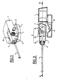
- a turret 1 intended to equip a military vehicle not shown and supporting an oscillating mass 2 enclosed in a box 3 of which only the barrel 4 is visible.
- the turret 1 comprises a base 5 for connecting it rotatably with respect to the vehicle on which it will be mounted.
- the turret 1 comprises an actuating means 6 for pivoting in site the oscillating mass 2 around left trunnions 7 and 29 right of which only the left trunnion is visible by considering the plane of the figure.
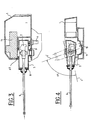
- the vertical section shows the integration of the oscillating mass 2, extended by the barrel 4, in the casing 3.
- the oscillating mass 2 is mounted in the turret 1 by means of the connection interface constituted by the caisson 3.
- the oscillating mass is provided with a gasket 8 ensuring tightness.
- the barrel 4 slides relative to the mass oscillating 2 at each shot in the box 3 using a mechanism 9, namely 9a, 9b, 9c, positioning.
- the rear portion 10 of the box 3 has a shape matching with the corresponding lower part 11 of the turret 1. This embodiment ensures the desired deflection of the oscillating weight without penalizing the available space of the turret.
- the weapon represented by its barrel 4 is able to slide during firing ammunition and the box 3 is itself mounted mobile site in said turret.
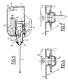
- the box 3 which is an AA cut of the figure 2 , we see that the box 3 is equipped with pins 7 and 29 on either side to secure it in the turret 1 and ensure its rotation in situ using the means 6 in a known manner.
- the means 6 consists for example of a motor secured to the turret and whose output gear meshes with a wheel integral with the oscillating mass.
- the turret comprises a block 13 for storing and transferring the ammunition to the weapon 2. It can also be seen that the interior of the caisson 3 communicates through the trunnion 29 with the inside I of the turret 1.
- trunnions 7 and 29 are constituted by a boring large diameter and extended by an outer ring on which the hinge bearing of the box relative to the turret is mounted. This joint is sealed with respect to the medium outside the turret in a known manner, for example by means of a lip seal, said interface thus ensuring the mobility of the gun.
- the two extreme positions of the box 3 with respect to the turret 1 are represented, positions which are obtained by means of the actuating means 6.
- the angle a defines the angle of deflection of the barrel 4 between a position 4 4 'and 4 "positions are of the order of 100 °.
- the turret according to the invention allows both to seal against the outside and a significant clearance of the barrel without disrupting the operation of the weapon while providing a simple architecture.
- the caisson 3 is provided with a non-return valve 40 of communication with the outside allowing the adjustment of the pressure prevailing therein.
- the turret 1 is equipped with means 14 for suctioning and filtering the outside air. This air intake is designed to overpressure the turret 1 relative to the outside environment and exhaust the stale air to the outside. The overpressure is of the order of 10% more than the external pressure.
- the air circuit is carried out in the following manner and is shown schematically by the arrows 16-23.
- the turret 1 also ensures the evacuation of empty sockets or ammunition pellets after firing. This evacuation is performed through the journals 7 and 29 which have a large diameter, that is to say a diameter sufficient to pass a medium caliber ammunition, for example 40 mm.
- the sleeve at its output of the oscillating mass is supported by a mechanism not shown, a pusher for example, which from the block 13 through the other pin 7 to its complete output.
- the Figures 6 and 7 represent the two main stages of this phase. Since the journals 7 and 29 are hollow for communicating the inside of the box and the inside of the turret 1, it is easy to interpose a calibrated sealing member 24 to communicate the turret 1 with the medium outside.
- the member 24 may be for example a diaphragm whose lips remain closed between the passage of two consecutive sleeves as shown in FIG. figure 6 . The opening of these lips is controlled during the passage of the sleeve 25 as shown on the figure 7 . During its advance generated by the pusher the sleeve causes the opening of the means 24. Since the inside of the turret is overpressure, a leak in the member 24 does not pose a problem.
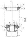
- FIG 8 there is shown the detail of the connection between the trunnion and the turret to ensure the rotation of the interface 2 relative to the turret 1 with the left and right trunnions 7 and 29.
- a left bearing 30 and a right bearing 31 are provided on either side of the interface 2, with reference to the plane of the figure.
- the outer cage 33 of the left bearing 30 is integral with the turret while the inner cage 32 is secured to the interface 2.
- the outer cage 33 has no particular features while the inner cage 32 supports a connection mechanism 34 of the interface 2.
- This mechanism 34 comprises in particular a cylindrical tube 35 whose inner diameter is provided to allow the passage of the empty sleeve.
- the outer cage 36 of the right bearing 31 has no particularity and the inner cage 37 has an internal diameter sufficient to ensure the passage of the This internal diameter may be greater than that of the cylindrical tube as shown in the figure to facilitate this introduction.
- a pusher represented in the form of the arrow 38 supplies the interface 2 with ammunition.
- the empty sockets that leave the left side can be accumulated in a bag 39 hooked to the end of the tube 35.
- sealing means are provided at the left bearing 30. These means being conventional do not have to be explained.
Landscapes
- Engineering & Computer Science (AREA)
- General Engineering & Computer Science (AREA)
- Aiming, Guidance, Guns With A Light Source, Armor, Camouflage, And Targets (AREA)
- Vibration Dampers (AREA)
- Mechanical Operated Clutches (AREA)
- Stored Programmes (AREA)
- Refuge Islands, Traffic Blockers, Or Guard Fence (AREA)
- Body Structure For Vehicles (AREA)
- Vehicle Cleaning, Maintenance, Repair, Refitting, And Outriggers (AREA)
Description
- Le secteur technique de la présente invention est celui des tourelles destinées aux véhicules militaires et supportant une masse oscillante intégrant un canon.
- Le montage d'une masse oscillante sur une tourelle permet généralement le débattement de cette masse oscillante suivant une rotation autour d'un axe fixe par rapport à la tourelle, appelée communément rotation en site. Par ailleurs, la tourelle est elle-même mobile en rotation par rapport au véhicule, appelée communément rotation en gisement. Cette dernière rotation ne pose en général pas de problèmes particuliers. Par contre, la rotation en site pose des problèmes difficiles à résoudre pour des débattements du canon de l'arme de l'ordre de 100° par rapport à la tourelle.
- Il s'avère indispensable d'isoler vis-à-vis de l'extérieur la tourelle afin d'éviter une contamination et d'assurer l'évacuation des gaz de combustion produits lors du tir des munitions et bien entendu des douilles vides ou des culots après le tir des munitions.
- D'autre part, la masse oscillante est pilotée et alimentée à partir de la tourelle, ce qui impose d'établir une communication pour assurer ces fonctions tout en évitant la propagation des résidus gazeux de combustion du canon vers la tourelle.
- Enfin, la masse oscillante est mise en communication avec le milieu extérieur pour évacuer les gaz de combustion et les douilles ou culots et il convient là aussi d'assurer l'étanchéité de la masse oscillante par rapport au milieu extérieur.
- On a déjà proposé une tourelle dans laquelle celle-ci est isolée par rapport au milieu extérieur en interposant des moyens d'étanchéité entre cette tourelle et la masse oscillante. Pour cela, on monte un joint sur la tourelle circulant autour de la fenêtre nécessaire au débattement prévu de la masse oscillante. Le contact de la lèvre du joint sur une surface cylindrique centrée sur l'axe de rotation de la masse oscillante et liée à la masse oscillante permet d'assurer cette étanchéité. Toutefois, cette solution nécessite un rayon pour la surface cylindrique d'autant plus grand que le débattement de la masse oscillante est important. Ainsi, pour de grands débattements de la masse oscillante, par exemple de 100°, la hauteur de la tourelle présente un handicap pour son encombrement, pour sa discrétion ou encore pour la masse de l'ensemble. De plus, ce joint produit, par son frottement, une perturbation par une résistance à la rotation de la masse oscillante. Cette perturbation n'est pas souhaitable car elle équivaut à un frottement sec qui perturbe le pointage précis de la masse oscillante sur une cible à l'aide d'une consigne envoyée par des asservissements aux moyens de positionnement en site de ladite masse.
- Le brevet
US-3854377 décrit une tourelle pour véhicule mobile en gisement par rapport au véhicule et supportant une masse oscillante comprenant un canon orienté en site. Dans cette tourelle, les douilles vides sont évacuées vers l'intérieur du véhicule, et non pas à l'extérieur. - Le but de la présente invention est de concevoir une nouvelle organisation de la structure d'une tourelle portant une masse oscillante permettant d'assurer un débattement important de la masse oscillante et une isolation par rapport au milieu extérieur et, ce, quelle que soit la position angulaire de la masse oscillante.
- L'invention a donc pour objet une tourelle pour véhicule militaire mobile en gisement par rapport audit véhicule et supportant une masse oscillante comprenant notamment un canon orienté en site, la masse oscillante étant montée dans la tourelle à l'aide d'une interface de liaison, ladite interface assurant la mobilité en site du canon, l'interface est constituée d'un caisson fermé à l'intérieur duquel l'arme est apte à coulisser au cours du tir des munitions, ledit caisson étant monté mobile en site dans ladite tourelle par l'intermédiaire d'un tourillon gauche et d'un tourillon droit et le tourillon gauche étant creux et communiquant avec l'extérieur, caractérisée en ce que l'interface de liaison assure l'étanchéité de ladite masse par rapport au milieu extérieur à la tourelle par l'intermédiaire d'un organe d'étanchéité calibré au travers duquel l'évacuation des douilles est réalisée.
- Selon encore une caractéristique de l'invention, le tourillon droit est creux pour mettre en communication l'intérieur du caisson et l'intérieur de la tourelle
- Selon une autre caractéristique de l'invention, le caisson est muni d'une valve anti-retour de communication avec l'extérieur permettant l'ajustement de la pression régnant à l'intérieur de celui-ci.
- Selon encore une autre caractéristique de l'invention, les tourillons présentent un diamètre interne suffisant pour assurer le passage des douilles de munitions et leur évacuation vers l'extérieur de la tourelle.
- Selon encore une autre caractéristique de l'invention, la tourelle peut comporter un moyen .de réception des douilles fixé à l'organe d'étanchéité.
- Selon encore une autre caractéristique de l'invention, la tourelle est équipée d'un moyen d'aspiration et de filtration de l'air extérieur pour assurer une surpression à l'intérieur de la tourelle.
- Selon encore une autre caractéristique de l'invention, le caisson est articulé par l'intermédiaire de roulements montés sur les tourillons.
- Selon encore une autre caractéristique de l'invention, la tourelle peut comporter un moyen de stockage des douilles solidaire de l'organe d'étanchéité.
- Avantageusement, la tourelle est équipée d'un canon de moyen calibre, par exemple un canon de 40 mm.
- Un tout premier avantage de la tourelle selon l'invention réside dans la conception simple de la masse oscillante intégrée dans la tourelle pour assurer un grand débattement.
- Un autre avantage réside dans l'intégration facilitée des moyens d'étanchéité de la masse oscillante.
- Un autre avantage réside dans le fait que l'étanchéité de la tourelle est assurée par la masse oscillante.
- Un autre avantage encore réside dans le fait que les frottements secs sont réduits, ce qui réduit les perturbations de pointage de la masse oscillante.
- Un autre avantage encore de l'invention réside dans le fait que la rigidité du caisson fermé contribue à placer les premiers modes de la fréquence d'excitation du caisson à une valeur supérieure donnée par les mouvements de la masse oscillante commandée par l'actionneur.
- D'autres caractéristiques, détails et avantages de l'invention ressortiront plus clairement de la description donnée ci-après à titre indicatif en relation avec des dessins dans lesquels :
- la
figure 1 est une vue générale de la tourelle, - la
figure 2 est une coupe verticale de la tourelle passant par l'axe du canon, - la
figure 3 est une coupe AA de lafigure 2 , - la
figure 4 montre le débattement de la masse oscillante par rapport à la tourelle, - la
figure 5 illustre la circulation de l'air dans la tourelle, - les
figures 6 et 7 montrent l'expulsion d'une douille vide vers l'extérieur, et - la
figure 8 est une coupe montrant les tourillons. - Sur la
figure 1 , on a représenté une tourelle 1 destinée à équiper un véhicule militaire non représenté et supportant une masse oscillante 2 enfermée dans un caisson 3 dont seul le canon 4 est visible. La tourelle 1 comporte une embase 5 permettant de la relier de manière rotative par rapport au véhicule sur lequel elle sera montée. La tourelle 1 comporte un moyen d'actionnement 6 permettant de faire pivoter en site la masse oscillante 2 autour de tourillons gauche 7 et 29 droit dont seul le tourillon de gauche est visible en considérant le plan de la figure. - Sur la
figure 2 , la coupe verticale montre l'intégration de la masse oscillante 2, prolongée par le canon 4, dans le caisson 3. On voit que la masse oscillante 2 est montée dans la tourelle 1 à l'aide de l'interface de liaison constituée du caisson 3. Au niveau du canon 4, la masse oscillante est munie d'un joint 8 assurant l'étanchéité. Le canon 4 coulisse par rapport à la masse oscillante 2 à chaque tir dans le caisson 3 à l'aide d'un mécanisme 9, à savoir 9a, 9b, 9c, de positionnement. La partie arrière 10 du caisson 3 présente une concordance de forme avec la partie basse 11 correspondante de la tourelle 1. Cette réalisation permet d'assurer le débattement souhaité de la masse oscillante sans pénaliser l'espace disponible de la tourelle. L'arme représentée par son canon 4 est apte à coulisser au cours du tir des munitions et le caisson 3 est lui-même monté mobile en site dans ladite tourelle. - Sur la
figure 3 , qui est une coupe AA de lafigure 2 , on voit que le caisson 3 est équipé de tourillons 7 et 29 de part et d'autre permettant de le fixer dans la tourelle 1 et d'assurer sa rotation en site à l'aide du moyen 6 de façon connue. Le moyen 6 est constitué par exemple d'un moteur solidaire de la tourelle et dont le pignon de sortie engrène sur une roue solidaire de la masse oscillante. La tourelle comporte un bloc 13 de stockage et de transfert des munitions vers l'arme 2. On voit également que l'intérieur du caisson 3 communique par le tourillon 29 avec l'intérieur I de la tourelle 1. Ces tourillons 7 et 29 sont constitués par un percement de diamètre important et prolongé par une couronne extérieure sur laquelle le roulement d'articulation du caisson par rapport à la tourelle est monté. Cette articulation est rendue étanche par rapport au milieu extérieur à la tourelle de manière connue, par exemple à l'aide d'un joint à lèvres, ladite interface assurant ainsi la mobilité en site du canon. - Sur la
figure 4 , on a représenté les deux positions extrêmes du caisson 3 par rapport à la tourelle 1, positions qui sont obtenues à l'aide du moyen d'actionnement 6. L'angle a définit l'angle de débattement du canon 4 entre une position 4' haute et une position 4" basse. L'angle de débattement entre les positions 4' et 4" est de l'ordre de 100°. Ainsi, si on considère une position de départ d'angle α nul du canon 4, la position 4' définit un angle de +85° environ et la position 4" un angle de - 15° environ. On voit encore sur la figure que dans la position 4', la partie arrière 10 du caisson 3 vient épouser la forme complémentaire 11 en regard de la tourelle. Ainsi, la tourelle selon l'invention permet à la fois d'assurer l'étanchéité vis-à-vis de l'extérieur et un débattement important du canon sans perturber le fonctionnement de l'arme tout en offrant une architecture simple. - Sur la
figure 5 , on a représenté le principe de circulation de l'air dans la tourelle 1 et l'interface 2 et plus précisément du caisson 3. Le caisson 3 est muni d'une valve 40 anti-retour de communication avec l'extérieur permettant l'ajustement de la pression régnant à l'intérieur de celui-ci. La tourelle 1 est équipée d'un moyen 14 d'aspiration et de filtration de l'air extérieur. Cette aspiration d'air est prévue pour mettre en surpression la tourelle 1 par rapport au milieu extérieur et évacuer l'air vicié vers l'extérieur. La surpression est de l'ordre de 10% de plus que la pression extérieur. Le circuit de l'air s'effectue de la manière suivante et est schématisé par les flèches 16-23. L'air pénètre en 16 en étant aspiré par l'aspirateur 14 et circule à l'intérieur de la tourelle 1 à travers le bloc 13 en 18 et entre le bloc 13 et la paroi de la tourelle en 19 ; il arrive ensuite au niveau du tourillon 29 en 20 pour circuler dans l'interface 2 pour s'échapper soit par le tourillon en 21 soit par la valve 40 en 22 et 23. Etant donné que l'aspirateur 14 crée une surpression dans la tourelle, l'isolation est assurée en conséquence. - La tourelle 1 selon l'invention permet également d'assurer l'évacuation des douilles vides ou des culots de munitions après le tir. Cette évacuation est réalisée à travers les tourillons 7 et 29 qui présentent un grand diamètre, c'est-à-dire un diamètre suffisant pour faire passer une munition de moyen calibre, par exemple de 40 mm. A cette fin, la douille à sa sortie de la masse oscillante est prise en charge par un mécanisme non représenté, un poussoir par exemple, qui depuis le bloc 13 la fait traverser l'autre tourillon 7 jusqu'à sa sortie complète.
- Les
figures 6 et 7 représentent les deux étapes principales de cette phase. Etant donné que les tourillons 7 et 29 sont creux pour mettre en communication l'intérieur du caisson et l'intérieur de la tourelle 1, il est facile d'interposer un organe d'étanchéité 24 calibré pour faire communiquer la tourelle 1 avec le milieu extérieur. L'organe 24 peut être par exemple un diaphragme dont les lèvres restent fermées entre le passage de deux douilles consécutives comme représenté sur lafigure 6 . L'ouverture de ces lèvres est commandée lors du passage de la douille 25 comme représentée sur lafigure 7 . Au cours de son avancée engendrée par le poussoir la douille vient provoquer l'ouverture du moyen 24. Etant donné que l'intérieur de la tourelle est en surpression, une fuite au niveau de l'organe 24 ne pose pas de problème. Il y a donc fuite d'air mais l'air vicié extérieur ne peut pénétrer à l'intérieur de la tourelle. Sur lafigure 7 , on a représenté la position d'expulsion de la douille 25 qui a traversé partiellement l'organe 24 d'étanchéité. A la fin de sa course, la douille vide tombe par exemple dans un sac de récupération pour être évacuée ultérieurement. - Sur la
figure 8 , on a représenté le détail de réalisation de la liaison entre le tourillon et la tourelle permettant d'assurer la rotation de l'interface 2 par rapport à la tourelle 1 à l'aide des tourillons gauche 7 et droit 29. A cette fin, on prévoit de part et d'autre de l'interface 2 un roulement gauche 30 et un roulement droit 31 en se référant dans le plan de la figure. La cage externe 33 du roulement gauche 30 est solidaire de la tourelle tandis que la cage interne 32 est solidaire de l'interface 2. La cage externe 33 ne présente pas de particularités alors que la cage interne 32 supporte un mécanisme de connexion 34 de l'interface 2. Ce mécanisme 34 comprend notamment un tube cylindrique 35 dont le diamètre interne est prévu pour permettre le passage de la douille vide. La cage externe 36 du roulement droit 31 ne présente pas de particularité et la cage interne 37 présente un diamètre interne suffisant pour assurer le passage de la Ce diamètre interne peut être supérieur à celui du tube cylindrique comme cela apparaît sur la figure pour faciliter cette introduction. Un poussoir représenté sous la forme de la flèche 38 permet d'alimenter l'interface 2 en munitions. Les douilles vides qui sortent côté gauche peuvent être accumulées dans un sac 39 accroché à l'extrémité du tube 35. Bien entendu, des moyens d'étanchéité sont prévus au niveau du roulement gauche 30. Ces moyens étant classiques n'ont pas à être explicités.
Claims (10)
- Tourelle (1) pour véhicule militaire mobile en gisement par rapport audit véhicule et supportant une masse oscillante (2) comprenant notamment un canon (4) orienté en site, la masse oscillante (2) étant montée dans la tourelle (1) à l'aide d'une interface de liaison (3), ladite interface (3) assurant la mobilité en site du canon, l'interface est constituée d'un caisson (3) fermé à l'intérieur duquel l'arme est apte à coulisser au cours du tir des munitions, ledit caisson étant monté mobile en site dans ladite tourelle (1) par l'intermédiaire d'un tourillon gauche (7) et d'un tourillon droit (29) et le tourillon gauche (7) étant creux et communiquant avec l'extérieur, caractérisée en ce que l'interface de liaison (3) assure l'étanchéité de ladite masse par rapport au milieu extérieur à la tourelle par l'intermédiaire d'un organe d'étanchéité calibré (24) au travers duquel l'évacuation des douilles est réalisée.
- Tourelle pour véhicule militaire selon la revendication 1, caractérisée en ce que le tourillon droit (29) est creux pour mettre en communication l'intérieur du caisson (3) et l'intérieur de la tourelle.
- Tourelle pour véhicule militaire selon la revendication 1, caractérisée en ce que le caisson (3) est muni d'une valve (40) anti-retour de communication avec l'extérieur permettant l'ajustement de la pression régnant à l'intérieur de celui-ci.
- Tourelle pour véhicule militaire selon la revendication 3, caractérisée en ce que les tourillons (7, 29) présentent un diamètre interne suffisant pour assurer le passage des munitions et leur évacuation vers l'extérieur de la tourelle.
- Tourelle pour véhicule militaire selon la revendication 1, caractérisée en ce qu'elle comporte un moyen de réception (39) des douilles fixé à l'organe d'étanchéité (24).
- Tourelle pour véhicule militaire selon l'une quelconque des revendications précédentes, caractérisée en ce qu'elle est équipée d'un moyen (14) d'aspiration et de filtration de l'air extérieur pour assurer une surpression à l'intérieur de la tourelle.
- Tourelle pour véhicule miliaire selon l'une quelconque des revendications précédentes, caractérisée en ce que le caisson (3) est articulé par l'intermédiaire de roulements (30, 31) montés sur les tourillons.
- Tourelle pour véhicule militaire selon la revendication 6, caractérisée en ce qu'elle comporte un moyen (39) de stockage des douilles solidaire de l'organe d'étanchéité.
- Tourelle pour véhicule militaire selon l'une quelconque des revendications précédentes, caractérisée en ce qu'elle est équipée d'un canon de moyen calibre.
- Tourelle pour véhicule militaire selon la revendication 9, caractérisée en ce qu'elle est équipée d'un canon de 40 mm.
Applications Claiming Priority (3)
| Application Number | Priority Date | Filing Date | Title |
|---|---|---|---|
| FR0200731A FR2835048B1 (fr) | 2002-01-22 | 2002-01-22 | Tourelle pour vehicule militaire |
| FR0200731 | 2002-01-22 | ||
| PCT/FR2003/000214 WO2003062732A1 (fr) | 2002-01-22 | 2003-01-22 | Tourelle pour vehicule militaire |
Publications (2)
| Publication Number | Publication Date |
|---|---|
| EP1468240A1 EP1468240A1 (fr) | 2004-10-20 |
| EP1468240B1 true EP1468240B1 (fr) | 2010-04-07 |
Family
ID=27589542
Family Applications (1)
| Application Number | Title | Priority Date | Filing Date |
|---|---|---|---|
| EP03731737A Expired - Lifetime EP1468240B1 (fr) | 2002-01-22 | 2003-01-22 | Tourelle pour vehicule militaire |
Country Status (7)
| Country | Link |
|---|---|
| US (1) | US7021189B2 (fr) |
| EP (1) | EP1468240B1 (fr) |
| AT (1) | ATE463712T1 (fr) |
| DE (1) | DE60332000D1 (fr) |
| FR (1) | FR2835048B1 (fr) |
| IL (2) | IL162918A0 (fr) |
| WO (1) | WO2003062732A1 (fr) |
Cited By (1)
| Publication number | Priority date | Publication date | Assignee | Title |
|---|---|---|---|---|
| US11156417B2 (en) | 2017-02-02 | 2021-10-26 | Nexter Systems | Cap for duct for ejecting cartridges and turret including a duct for ejecting cartridges obturated by such a cap |
Families Citing this family (26)
| Publication number | Priority date | Publication date | Assignee | Title |
|---|---|---|---|---|
| DE102009020161A1 (de) * | 2009-05-04 | 2010-11-11 | Esw Gmbh | Aufsatzeinrichtung für Fahrzeuge |
| DE202009007415U1 (de) | 2009-05-25 | 2010-08-26 | Rheinmetall Waffe Munition Gmbh | Modularer Waffenträger |
| DE102010031898A1 (de) | 2010-07-21 | 2012-01-26 | Rheinmetall Air Defence Ag | Fernsteuerbares Geschütz |
| US8930066B2 (en) * | 2011-01-21 | 2015-01-06 | Control Solutions LLC | Customizable control apparatus and method for a vehicle turret |
| US8607686B2 (en) | 2011-01-21 | 2013-12-17 | Control Solutions LLC | Controlled vehicle turret apparatus and method |
| US8428827B2 (en) | 2011-01-21 | 2013-04-23 | Control Solutions LLC | Apparatus and method for controlling rotational movement of a vehicle turret |
| US8640596B1 (en) * | 2011-09-07 | 2014-02-04 | The United States Of America As Represented By The Secretary Of The Navy | Gas extraction system retrofit kit for gun weapon system |
| FR2991763B1 (fr) * | 2012-06-07 | 2014-06-20 | Panhard General Defense | Plateau tournant motorise pour elements additionnels de tourelle. |
| USD753543S1 (en) | 2013-06-14 | 2016-04-12 | Wargaming.Net Llp | Armored vehicle |
| USD736793S1 (en) * | 2013-08-26 | 2015-08-18 | Wargaming.Net Llp | Display device portion with a graphical user interface showing an armored vehicle |
| USD742895S1 (en) * | 2013-08-26 | 2015-11-10 | Wargaming.Net Llp | Display device portion with a graphical user interface showing an armored vehicle |
| USD742393S1 (en) * | 2013-08-26 | 2015-11-03 | Wargaming.Net Llp | Display device portion with a graphical user interface showing an armored vehicle |
| USD741346S1 (en) * | 2013-10-17 | 2015-10-20 | Wargaming.Net Llp | Display device portion with a graphical user interface showing an armored vehicle |
| USD736799S1 (en) * | 2013-10-18 | 2015-08-18 | Wargaming.Net Llp | Display device portion with a graphical user interface showing an armored vehicle |
| FR3014372B1 (fr) * | 2013-12-05 | 2015-12-04 | Nexter Systems | Dispositif de distribution d'air de climatisation pour une tourelle d'un vehicule et vehicule comportant un tel dispositif |
| FR3022020A1 (fr) | 2014-06-10 | 2015-12-11 | Nexter Systems | Dispositif d'extraction de douille |
| US9328986B1 (en) | 2014-11-04 | 2016-05-03 | Oshkosh Corporation | Turret assembly |
| US9194664B1 (en) * | 2015-02-19 | 2015-11-24 | The United States Of America As Represented By The Secretary Of The Army | Main gun shield for battle tank |
| EP3306259A1 (fr) | 2016-10-10 | 2018-04-11 | CMI Defence S.A. | Structure standard et interchangeable pour un véhicule blindé |
| FR3056738B1 (fr) * | 2016-09-23 | 2019-04-12 | Nexter Systems | Tourelle pour vehicule blinde |
| FR3072906B1 (fr) * | 2017-11-02 | 2019-09-20 | Nexter Systems | Distributeur d'air et tourelle equipee d'un tel distributeur d'air |
| USD900677S1 (en) * | 2018-04-17 | 2020-11-03 | Fnss Savunma Sistemleri A.S. | Turret |
| EP4617613A1 (fr) * | 2024-03-12 | 2025-09-17 | BAE SYSTEMS plc | Améliorations apportées à un sous-système d'arme |
| WO2025191235A1 (fr) * | 2024-03-12 | 2025-09-18 | Bae Systems Plc | Sous-système d'arme |
| GB2639224A (en) * | 2024-03-12 | 2025-09-17 | Bae Systems Plc | Further improvements to weapon sub-system |
| IT202400012451A1 (it) * | 2024-05-31 | 2025-12-01 | Leonardo Spa | Metodo per migliorare un sistema montato su un veicolo e veicolo dotato di un sistema migliorato mediante tale metodo |
Family Cites Families (14)
| Publication number | Priority date | Publication date | Assignee | Title |
|---|---|---|---|---|
| US1578310A (en) * | 1925-12-08 | 1926-03-30 | Jr Levin H Campbell | Vehicle of the type known as alpha tank |
| US2357209A (en) * | 1939-01-04 | 1944-08-29 | Lanciani Ettore | Armed rotating turret for aircraft |
| DE1193399B (de) * | 1964-01-14 | 1965-05-20 | Keller & Knappich Gmbh | Drehkranzlafette fuer Schnellfeuerwaffen auf Panzerfahrzeugen |
| LU47304A1 (fr) * | 1964-11-07 | 1966-05-09 | ||
| US3710681A (en) * | 1970-03-30 | 1973-01-16 | Efmc Corp | Gun mount closure or seal |
| US3854377A (en) * | 1972-05-20 | 1974-12-17 | Keller & Knappich Augsburg | Tank turret for automatic weapons |
| DE2551086A1 (de) * | 1975-11-14 | 1977-05-18 | Wegmann & Co | Einrichtung zur zeitweisen abdichtung des innenraumes von gepanzerten fahrzeugen, insbesondere von kampfpanzern, gegen das eindringen von fluessigen oder gasfoermigen stoffen |
| SE432669B (sv) * | 1979-10-02 | 1984-04-09 | Bofors Ab | Anordning for tetning av eldrorsoppningen i en vapenkupol |
| DE3325924A1 (de) * | 1983-07-19 | 1985-01-31 | Rheinmetall GmbH, 4000 Düsseldorf | Blendenlafettierung wenigstens einer automatischen rohrwaffe in beengter einbaulage |
| US4777864A (en) * | 1984-05-10 | 1988-10-18 | Ares, Inc. | Electronically controlled, externally powered, automatic gun |
| US4635529A (en) * | 1984-12-21 | 1987-01-13 | General Electric Company | Seal assembly |
| US4840108A (en) * | 1987-05-08 | 1989-06-20 | Werkzeugmaschinenfabrick Oerlikon-Buhrle Ag | Apparatus for the infeed of ammunition from an ammunition container to an automatic firing weapon |
| DE4206218C1 (de) * | 1992-02-28 | 1998-10-01 | Rheinmetall Ind Ag | Panzerturm |
| US6250197B1 (en) * | 1999-02-16 | 2001-06-26 | Paul H. Sanderson | Sponson tow-plate-mounted helicopter armament apparatus and associated methods |
-
2002
- 2002-01-22 FR FR0200731A patent/FR2835048B1/fr not_active Expired - Fee Related
-
2003
- 2003-01-22 US US10/501,408 patent/US7021189B2/en not_active Expired - Lifetime
- 2003-01-22 WO PCT/FR2003/000214 patent/WO2003062732A1/fr not_active Ceased
- 2003-01-22 DE DE60332000T patent/DE60332000D1/de not_active Expired - Lifetime
- 2003-01-22 AT AT03731737T patent/ATE463712T1/de not_active IP Right Cessation
- 2003-01-22 EP EP03731737A patent/EP1468240B1/fr not_active Expired - Lifetime
- 2003-01-22 IL IL16291803A patent/IL162918A0/xx unknown
-
2004
- 2004-07-08 IL IL162918A patent/IL162918A/en active IP Right Grant
Cited By (1)
| Publication number | Priority date | Publication date | Assignee | Title |
|---|---|---|---|---|
| US11156417B2 (en) | 2017-02-02 | 2021-10-26 | Nexter Systems | Cap for duct for ejecting cartridges and turret including a duct for ejecting cartridges obturated by such a cap |
Also Published As
| Publication number | Publication date |
|---|---|
| DE60332000D1 (de) | 2010-05-20 |
| IL162918A (en) | 2010-12-30 |
| US7021189B2 (en) | 2006-04-04 |
| WO2003062732A1 (fr) | 2003-07-31 |
| FR2835048A1 (fr) | 2003-07-25 |
| ATE463712T1 (de) | 2010-04-15 |
| EP1468240A1 (fr) | 2004-10-20 |
| US20050115396A1 (en) | 2005-06-02 |
| IL162918A0 (en) | 2005-11-20 |
| FR2835048B1 (fr) | 2006-06-16 |
Similar Documents
| Publication | Publication Date | Title |
|---|---|---|
| EP1468240A1 (fr) | Tourelle pour vehicule militaire | |
| EP2169341B1 (fr) | Tourelleau escamotable manuellement | |
| FR2997151A1 (fr) | Amortisseur avec fonction ressort associee | |
| EP1129220B1 (fr) | Dispositif de repartition de matieres en vrac | |
| FR2819221A1 (fr) | Dispositif de mise a l'air libre destine a un reservoir de vehicule automobile | |
| FR3020409A1 (fr) | Assemblage pour turbomachine d'aeronef, comprenant un boitier de prelevement de puissance mecanique a acces simplifie | |
| FR2572803A1 (fr) | Systeme d'arme a tube monte dans un blinde | |
| EP3523594B1 (fr) | Dispositif d'éjection de douilles et/ou de maillons issus d'une chaîne ou bande de munitions associée à une arme principale et/ou secondaire | |
| EP2071268B1 (fr) | Tourelleau escamotable | |
| EP1535017B1 (fr) | Systeme de defense d'une cible comprenant un dispositif lanceur de projectiles | |
| EP0036811A1 (fr) | Mortier à tir rapide | |
| FR2755223A1 (fr) | Tourelle protegee pour vehicules blindes | |
| FR2549218A1 (fr) | Vehicule blinde equipe d'un mortier | |
| EP3699542B1 (fr) | Véhicule furtif avec système d'arme integré à déploiement rapide | |
| EP3179194B1 (fr) | Dispositif de manutention d'obus pour pièce d'artillerie | |
| FR2467379A1 (fr) | Tourelle de char a chargement automatique de l'arme | |
| EP2354488A1 (fr) | Dispositif de régulation de la phase liquide d'un circuit de refroidissement d'un moteur thermique | |
| EP0571266B1 (fr) | Système de chargement d'une munition dans une chambre pivotante d'une arme | |
| EP0017591B1 (fr) | Véhicule de combat à canon alimenté de façon automatique | |
| EP0045701B1 (fr) | Périscope de sous-marin | |
| EP4317903B1 (fr) | Montage d'arme et tourelle comportant un tel montage d'arme | |
| FR3022338A1 (fr) | Tourelleau comportant un magasin a munitions | |
| FR2670878A1 (fr) | Dispositif de chargement automatique d'une arme en munitions. | |
| EP0140053A2 (fr) | Mortier capable d'être monté sur un véhicule | |
| FR2503347A2 (fr) | Dispositif d'acheminement de munitions, du magasin au mecanisme de mise a feu d'une piece d'artillerie |
Legal Events
| Date | Code | Title | Description |
|---|---|---|---|
| PUAI | Public reference made under article 153(3) epc to a published international application that has entered the european phase |
Free format text: ORIGINAL CODE: 0009012 |
|
| 17P | Request for examination filed |
Effective date: 20040622 |
|
| AK | Designated contracting states |
Kind code of ref document: A1 Designated state(s): AT BE BG CH CY CZ DE DK EE ES FI FR GB GR HU IE IT LI LU MC NL PT SE SI SK TR |
|
| AX | Request for extension of the european patent |
Extension state: AL LT LV MK RO |
|
| 17Q | First examination report despatched |
Effective date: 20050727 |
|
| RAP1 | Party data changed (applicant data changed or rights of an application transferred) |
Owner name: NEXTER SYSTEMS |
|
| 17Q | First examination report despatched |
Effective date: 20050727 |
|
| GRAP | Despatch of communication of intention to grant a patent |
Free format text: ORIGINAL CODE: EPIDOSNIGR1 |
|
| GRAS | Grant fee paid |
Free format text: ORIGINAL CODE: EPIDOSNIGR3 |
|
| GRAA | (expected) grant |
Free format text: ORIGINAL CODE: 0009210 |
|
| AK | Designated contracting states |
Kind code of ref document: B1 Designated state(s): AT BE BG CH CY CZ DE DK EE ES FI FR GB GR HU IE IT LI LU MC NL PT SE SI SK TR |
|
| REG | Reference to a national code |
Ref country code: GB Ref legal event code: FG4D Free format text: NOT ENGLISH |
|
| REG | Reference to a national code |
Ref country code: CH Ref legal event code: EP |
|
| REG | Reference to a national code |
Ref country code: IE Ref legal event code: FG4D Free format text: LANGUAGE OF EP DOCUMENT: FRENCH |
|
| REF | Corresponds to: |
Ref document number: 60332000 Country of ref document: DE Date of ref document: 20100520 Kind code of ref document: P |
|
| REG | Reference to a national code |
Ref country code: NL Ref legal event code: VDEP Effective date: 20100407 |
|
| PG25 | Lapsed in a contracting state [announced via postgrant information from national office to epo] |
Ref country code: SI Free format text: LAPSE BECAUSE OF FAILURE TO SUBMIT A TRANSLATION OF THE DESCRIPTION OR TO PAY THE FEE WITHIN THE PRESCRIBED TIME-LIMIT Effective date: 20100407 |
|
| REG | Reference to a national code |
Ref country code: IE Ref legal event code: FD4D |
|
| PG25 | Lapsed in a contracting state [announced via postgrant information from national office to epo] |
Ref country code: SE Free format text: LAPSE BECAUSE OF FAILURE TO SUBMIT A TRANSLATION OF THE DESCRIPTION OR TO PAY THE FEE WITHIN THE PRESCRIBED TIME-LIMIT Effective date: 20100407 Ref country code: NL Free format text: LAPSE BECAUSE OF FAILURE TO SUBMIT A TRANSLATION OF THE DESCRIPTION OR TO PAY THE FEE WITHIN THE PRESCRIBED TIME-LIMIT Effective date: 20100407 Ref country code: ES Free format text: LAPSE BECAUSE OF FAILURE TO SUBMIT A TRANSLATION OF THE DESCRIPTION OR TO PAY THE FEE WITHIN THE PRESCRIBED TIME-LIMIT Effective date: 20100718 |
|
| PG25 | Lapsed in a contracting state [announced via postgrant information from national office to epo] |
Ref country code: FI Free format text: LAPSE BECAUSE OF FAILURE TO SUBMIT A TRANSLATION OF THE DESCRIPTION OR TO PAY THE FEE WITHIN THE PRESCRIBED TIME-LIMIT Effective date: 20100407 Ref country code: AT Free format text: LAPSE BECAUSE OF FAILURE TO SUBMIT A TRANSLATION OF THE DESCRIPTION OR TO PAY THE FEE WITHIN THE PRESCRIBED TIME-LIMIT Effective date: 20100407 |
|
| PG25 | Lapsed in a contracting state [announced via postgrant information from national office to epo] |
Ref country code: GR Free format text: LAPSE BECAUSE OF FAILURE TO SUBMIT A TRANSLATION OF THE DESCRIPTION OR TO PAY THE FEE WITHIN THE PRESCRIBED TIME-LIMIT Effective date: 20100708 Ref country code: CY Free format text: LAPSE BECAUSE OF FAILURE TO SUBMIT A TRANSLATION OF THE DESCRIPTION OR TO PAY THE FEE WITHIN THE PRESCRIBED TIME-LIMIT Effective date: 20100414 |
|
| PG25 | Lapsed in a contracting state [announced via postgrant information from national office to epo] |
Ref country code: EE Free format text: LAPSE BECAUSE OF FAILURE TO SUBMIT A TRANSLATION OF THE DESCRIPTION OR TO PAY THE FEE WITHIN THE PRESCRIBED TIME-LIMIT Effective date: 20100407 Ref country code: DK Free format text: LAPSE BECAUSE OF FAILURE TO SUBMIT A TRANSLATION OF THE DESCRIPTION OR TO PAY THE FEE WITHIN THE PRESCRIBED TIME-LIMIT Effective date: 20100407 Ref country code: IE Free format text: LAPSE BECAUSE OF FAILURE TO SUBMIT A TRANSLATION OF THE DESCRIPTION OR TO PAY THE FEE WITHIN THE PRESCRIBED TIME-LIMIT Effective date: 20100407 Ref country code: PT Free format text: LAPSE BECAUSE OF FAILURE TO SUBMIT A TRANSLATION OF THE DESCRIPTION OR TO PAY THE FEE WITHIN THE PRESCRIBED TIME-LIMIT Effective date: 20100809 |
|
| PLBE | No opposition filed within time limit |
Free format text: ORIGINAL CODE: 0009261 |
|
| STAA | Information on the status of an ep patent application or granted ep patent |
Free format text: STATUS: NO OPPOSITION FILED WITHIN TIME LIMIT |
|
| PG25 | Lapsed in a contracting state [announced via postgrant information from national office to epo] |
Ref country code: SK Free format text: LAPSE BECAUSE OF FAILURE TO SUBMIT A TRANSLATION OF THE DESCRIPTION OR TO PAY THE FEE WITHIN THE PRESCRIBED TIME-LIMIT Effective date: 20100407 Ref country code: CZ Free format text: LAPSE BECAUSE OF FAILURE TO SUBMIT A TRANSLATION OF THE DESCRIPTION OR TO PAY THE FEE WITHIN THE PRESCRIBED TIME-LIMIT Effective date: 20100407 |
|
| 26N | No opposition filed |
Effective date: 20110110 |
|
| PG25 | Lapsed in a contracting state [announced via postgrant information from national office to epo] |
Ref country code: IT Free format text: LAPSE BECAUSE OF FAILURE TO SUBMIT A TRANSLATION OF THE DESCRIPTION OR TO PAY THE FEE WITHIN THE PRESCRIBED TIME-LIMIT Effective date: 20100407 |
|
| BERE | Be: lapsed |
Owner name: NEXTER SYSTEMS Effective date: 20110131 |
|
| PG25 | Lapsed in a contracting state [announced via postgrant information from national office to epo] |
Ref country code: MC Free format text: LAPSE BECAUSE OF NON-PAYMENT OF DUE FEES Effective date: 20110131 |
|
| REG | Reference to a national code |
Ref country code: CH Ref legal event code: PL |
|
| PG25 | Lapsed in a contracting state [announced via postgrant information from national office to epo] |
Ref country code: CH Free format text: LAPSE BECAUSE OF NON-PAYMENT OF DUE FEES Effective date: 20110131 Ref country code: LI Free format text: LAPSE BECAUSE OF NON-PAYMENT OF DUE FEES Effective date: 20110131 |
|
| PG25 | Lapsed in a contracting state [announced via postgrant information from national office to epo] |
Ref country code: BE Free format text: LAPSE BECAUSE OF NON-PAYMENT OF DUE FEES Effective date: 20110131 |
|
| REG | Reference to a national code |
Ref country code: DE Ref legal event code: R119 Ref document number: 60332000 Country of ref document: DE Effective date: 20110802 |
|
| PG25 | Lapsed in a contracting state [announced via postgrant information from national office to epo] |
Ref country code: LU Free format text: LAPSE BECAUSE OF NON-PAYMENT OF DUE FEES Effective date: 20110122 |
|
| PG25 | Lapsed in a contracting state [announced via postgrant information from national office to epo] |
Ref country code: DE Free format text: LAPSE BECAUSE OF NON-PAYMENT OF DUE FEES Effective date: 20110802 |
|
| PG25 | Lapsed in a contracting state [announced via postgrant information from national office to epo] |
Ref country code: BG Free format text: LAPSE BECAUSE OF FAILURE TO SUBMIT A TRANSLATION OF THE DESCRIPTION OR TO PAY THE FEE WITHIN THE PRESCRIBED TIME-LIMIT Effective date: 20100707 Ref country code: TR Free format text: LAPSE BECAUSE OF FAILURE TO SUBMIT A TRANSLATION OF THE DESCRIPTION OR TO PAY THE FEE WITHIN THE PRESCRIBED TIME-LIMIT Effective date: 20100407 |
|
| PG25 | Lapsed in a contracting state [announced via postgrant information from national office to epo] |
Ref country code: HU Free format text: LAPSE BECAUSE OF FAILURE TO SUBMIT A TRANSLATION OF THE DESCRIPTION OR TO PAY THE FEE WITHIN THE PRESCRIBED TIME-LIMIT Effective date: 20100407 |
|
| REG | Reference to a national code |
Ref country code: FR Ref legal event code: PLFP Year of fee payment: 14 |
|
| REG | Reference to a national code |
Ref country code: FR Ref legal event code: PLFP Year of fee payment: 15 |
|
| REG | Reference to a national code |
Ref country code: FR Ref legal event code: PLFP Year of fee payment: 16 |
|
| PGFP | Annual fee paid to national office [announced via postgrant information from national office to epo] |
Ref country code: GB Payment date: 20211216 Year of fee payment: 20 Ref country code: FR Payment date: 20211215 Year of fee payment: 20 |
|
| REG | Reference to a national code |
Ref country code: GB Ref legal event code: PE20 Expiry date: 20230121 |
|
| PG25 | Lapsed in a contracting state [announced via postgrant information from national office to epo] |
Ref country code: GB Free format text: LAPSE BECAUSE OF EXPIRATION OF PROTECTION Effective date: 20230121 |