EP1467478A2 - Motor control apparatus and motor control method - Google Patents
Motor control apparatus and motor control method Download PDFInfo
- Publication number
- EP1467478A2 EP1467478A2 EP04008433A EP04008433A EP1467478A2 EP 1467478 A2 EP1467478 A2 EP 1467478A2 EP 04008433 A EP04008433 A EP 04008433A EP 04008433 A EP04008433 A EP 04008433A EP 1467478 A2 EP1467478 A2 EP 1467478A2
- Authority
- EP
- European Patent Office
- Prior art keywords
- current
- motor
- fundamental wave
- higher harmonic
- command value
- Prior art date
- Legal status (The legal status is an assumption and is not a legal conclusion. Google has not performed a legal analysis and makes no representation as to the accuracy of the status listed.)
- Granted
Links
Images




Classifications
-
- H—ELECTRICITY
- H02—GENERATION; CONVERSION OR DISTRIBUTION OF ELECTRIC POWER
- H02P—CONTROL OR REGULATION OF ELECTRIC MOTORS, ELECTRIC GENERATORS OR DYNAMO-ELECTRIC CONVERTERS; CONTROLLING TRANSFORMERS, REACTORS OR CHOKE COILS
- H02P21/00—Arrangements or methods for the control of electric machines by vector control, e.g. by control of field orientation
- H02P21/06—Rotor flux based control involving the use of rotor position or rotor speed sensors
Definitions
- the present invention relates to a motor control apparatus and a motor control method.
- Permanent magnet synchronous motors that do not require mechanical parts such as brushes, which become worn, and are compact and highly efficient are utilized widely as drive motors in electric cars and the like.
- the armature magnetic flux linkage generated by the permanent magnet changes sinusoidally relative to the phase.
- the vector control normally implemented on the motor current does not effectively prevent the occurrence of torque rippling and deterioration in the motor efficiency attributable to the higher harmonic components of the motor current.
- the higher harmonic component contained in a motor current is extracted and after the higher harmonic current component is converted to a value in the dhqh coordinate system, a higher harmonic current controller implements control so as to match the higher harmonic current with a higher harmonic current command value.
- the fundamental wave current control the motor current having been detected is converted to a value in the dq coordinate system and then a fundamental wave current controller implements control so as to match the fundamental wave current with a fundamental wave current command value.
- the motor current input to the fundamental wave current controller contains the higher harmonic component.
- the fundamental wave current controller which implements control so as to match the motor current with the fundamental wave current command value, tries to suppress the higher harmonic current component.
- the conformity of the higher harmonic current to its command value becomes affected and it becomes difficult to achieve the level of higher harmonic current control response desired in the control design specifications.
- the present invention provides a motor control apparatus and a motor control method that improves the conformity of the higher harmonic current to the command value in the higher harmonic current control.
- a motor control apparatus comprises a fundamental wave current control means for implementing feedback control on a fundamental wave component of a motor current flowing to a 3-phase AC motor in a dq coordinate system rotating in synchronization with the rotation of the motor, a higher harmonic current control means for implementing feedback control on a higher harmonic component of the motor current in a dhqh coordinate system rotating with a frequency which is an integral multiple of a frequency of the fundamental wave component of the motor current, a command value calculation means for calculating an AC voltage command value by adding an output from the fundamental wave current control means to an output from the higher harmonic current control means and outputs the AC voltage command value to a power conversion means for generating a 3-phase AC voltage corresponding to the AC voltage command value, and a higher harmonic component elimination means for eliminating the higher harmonic component of the motor current from a control deviation between a motor current feedback value and a fundamental wave current command value in the fundamental wave current control means.
- a method for controlling a motor by employing circuits including a fundamental wave current control circuit that implements feedback control on a fundamental wave component of a motor current in a dq coordinate system and a higher harmonic current control circuit that implements feedback control on a higher harmonic component of the motor current in a dhqh coordinate system
- the higher harmonic components of the motor current is eliminated from a control deviation between a fundamental wave current command value and a motor current feedback value in the fundamental wave current control circuit
- an AC voltage command value is calculated by adding an output from the fundamental wave current control circuit from which the higher harmonic component has been eliminated to an output from the higher harmonic current control circuit and a 3-phase AC voltage corresponding to the AC voltage command value is generated and the 3-phase AC voltage is applied to a 3-phase AC motor.
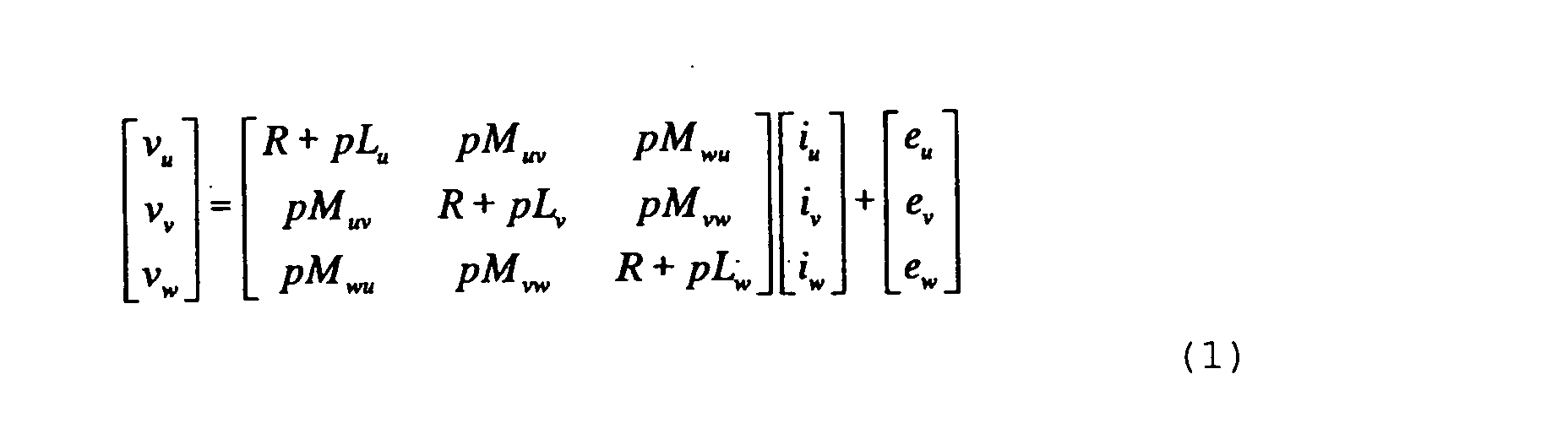
- Expression (1) presented below is a circuit equation pertaining to a permanent magnet synchronous motor driven with a 3-phase alternating current.
- vu, vv and vw represent the voltages at the individual phases (U-phase, V-phase and W-phase)
- iu, iv and iw represent the currents at the individual phases
- eu, ev and ew represent the speed electromotive forces at the individual phases attributable to the magnet
- Lu, Lv and Lw represent the self-inductances at the individual phases
- Muv, Mvw and Mwu represent mutual inductances between the phases
- R represents the armature resistance
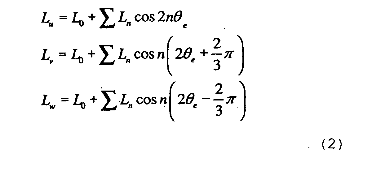
- the inductances When the inductances are expressed by incorporating the spatial changes in the inductances, the self-inductances are expressed as in expression (2) below and the mutual inductances are expressed as in expression (3).
- ⁇ e represents the electrical phase of the rotor.
- n is a natural number.
- the speed electromotive forces eu, ev and ew induced by the permanent magnet are expressed as in expression (4).
- w e represents the electrical angular speed
- ⁇ ' represents the fundamental wave component in the flux linkage
- ⁇ m' represents the higher harmonic component in the flux linkage
- m represents a natural number equal to or greater than 2.
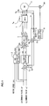
- FIG. 1 is a control block diagram of a 3-phase synchronous motor which is controlled through standard vector control.
- the vector control in the known art is first explained in reference to FIG. 1.
- Current sensors 9a and 9b respectively detect a U-phase current iu and a W-phase current iw at a 3-phase synchronous motor 11.
- a dq ⁇ 3-phase converter 6 executes a coordinate conversion to convert the currents iu and iw detected by the current sensors 9a and 9b to currents id and iq in a dq coordinate system.
- the dq coordinate system rotates in synchronization with the fundamental wave component of the magnetic flux at the 3-phase synchronous motor 11.
- the phase ⁇ e utilized by the dq ⁇ 3-phase converter 6 when the coordinate conversion is executed represents the position of the rotor at the 3-phase synchronous motor 11 expressed as an electrical phase.
- the rotor position is first detected with a rotary position sensor 10 such as an encoder or a resolver, and then, based upon the rotor position, the electrical phase ⁇ e is calculated by a phase speed computing unit 8.
- the phase speed computing unit 8 also calculates the electrical angular speed ⁇ e of the 3-phase synchronous motor 11 through time differentiation of the phase ⁇ e.
- the d-axis current id and the q-axis current iq obtained by the dq ⁇ 3-phase converter 6 are controlled through feedback control so as to respectively match a d-axis current command value id* and a q-axis current command value iq*.
- subtractors 1a and 1b calculate current control deviations (id* - id) and (iq* - iq) of the d-axis current id and the q-axis current iq relative to the d-axis current command value id* and the q-axis current command value iq* respectively.
- a dq-axis current controller 2 implements PI control on the current control deviations (id* - id) and (iq* - iq) . Namely, a d-axis control voltage vd and a q-axis control voltage vq which will set the current control deviations to 0 are determined.
- a non-interactive controller 3 obtains a d-axis compensating voltage vd_cmp and a q-axis compensating voltage vq_cmp through expressions (5) and (6) presented below based upon the motor angular speed ⁇ e, the d-axis current command value id* and the q-axis current command value iq*, in order to achieve a feed-forward compensation for the d-axis and q-axis interference.
- Lq represents the fundamental wave component in the q-axis inductance
- Ld represents the fundamental wave component in the d-axis inductance
- ⁇ ⁇ (3/2) ⁇ ⁇ '.
- Adders 4a and 4b respectively calculate a d-axis control voltage command value vd* and a q-axis control voltage command value vq* by adding the compensating voltages vd_cmp and vq_cmp output by the non-interactive controller 3 to the d-axis control voltage vd and the q-axis control voltage vq output by the dq-axis current controller 2.
- a dq ⁇ 3-phase converter 5 converts the d-axis control voltage vd* and the q-axis control voltage vq* to 3-phase voltage command values vu*, vv* and vw*.
- An inverter 7 executes a PWM (pulse width modulation) control based upon the 3-phase voltage command values vu*, vv* and vw*, thereby converting the DC power from a DC source 7a to 3-phase AC power.
- the 3-phase AC power resulting from the conversion is then supplied to the 3-phase synchronous motor 11.
- a higher harmonic current in the 3-phase synchronous motor 11 is controlled in a coordinate system which rotates at a rate that is an integral multiple of the fundamental wave components of the motor currents, as explained later.
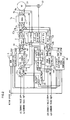
- FIG. 2 is a block diagram of the structure adopted in the motor control apparatus in the first embodiment. It is to be noted that the same reference numerals are assigned to components identical to those shown in FIG. 1, and the following explanation focuses on the differences fromthe apparatus shown in FIG. 1.
- a new coordinate system i.e., a dhqh coordinate system, which rotates in synchronization with the higher harmonic current that is a target of control, is set and the higher harmonic current is controlled in the dhqh coordinate system.
- the motor control apparatus in FIG. 2 includes a dq-axis current controller (fundamental wave current controller) 2 and a dhqh-axis current controller (higher harmonic current controller) 15, which can be integrated in a single microprocessor.
- the dq-axis current controller 2 implements feedback control on the fundamental wave component of the motor current in the dq-axis coordinate system which rotates in synchronization with the rotation of the motor 11.
- the dhqh-axis current controller 15 implements feedback control on the higher harmonic component of the motor current in the dhqh coordinate system.
- the dhqh coordinate system is an orthogonal coordinate system rotating with a frequency that is an integral multiple of the frequency of the fundamental wave component in the motor current.
- a higher harmonic extraction unit 12 extracts the higher harmonic currents contained in the d-axis current and q-axis current.
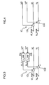
- FIG. 3 shows in detail the structure adopted in the higher harmonic extraction unit 12.
- the d-axis and q-axis current command values id* and iq* are passed through low-pass filters (LPF) 12a and 12b and thus, estimated current response values id_i and iq_i are respectively obtained.
- LPF low-pass filters
- the cutoff frequencies at the low-pass filters 12a and 12b should be set in advance to the control response frequency of the dq-axis current controller 2.
- the estimated current response value id_i thus obtained is subtracted from the d-axis current id by a subtractor 12c, and as a result, a d-axis higher harmonic current id_high is determined.
- the estimated current response value iq_i is subtracted from the q-axis current iq by a subtractor 12d, and as a result, a q-axis higher harmonic current iq_high is determined.
- the low-pass filters 12a and 12b in the higher harmonic extraction unit 12 may be omitted, as shown in FIG. 4. Namely, the value obtained by subtracting the d-axis current command value id* from the d-axis current id may be set as the d-axis higher harmonic current id_high, and the value obtained by subtracting the q-axis current command value iq* from the q-axis current iq may be set as the q-axis higher harmonic current iq_high.
- the d-axis current response and the q-axis current response both achieve values close to the response frequency set for the dq-axis current controller 2 on the control design stage. If, on the other hand, the low-pass filters 12a and 12b are omitted (see FIG. 4), the d-axis current response and the q-axis current response achieve values higher than the response frequency set on the control design stage.
- the d-axis higher harmonic current id_high and the q-axis higher harmonic current iq_high obtained at the higher harmonic extraction unit 12 are input to a dhqh ⁇ dq converter 13.
- the dhqh ⁇ dq converter 13 converts id_high and iq_high respectively to values idh and iqh in the dhqh coordinate system.
- a phase ⁇ eh used by the dhqh ⁇ dq converter 13 when the coordinate conversion is executed can be determined through the following expression (7) by using the degree k of the higher harmonic in the dq coordinate system.
- ⁇ eh k ⁇ ⁇ e
- Subtractors 14a and 14b subtract the higher harmonic current idh and iqh in the dhqh coordinate system respectively from higher harmonic current command values idh* and iqh* and thus obtain higher harmonic current control deviations (idh* - idh) and (iqh* - iqh).
- a dhqh-axis current controller 15 which may be constituted with, for instance, a PI controller, calculates control voltages vdh and vqh to set the higher harmonic current control deviations to 0.
- a circuit equation in the dhqh coordinate system can be modified based upon expression (1) to the following expression (8).
- expression (8) the spatial higher harmonics in the self-inductances and the mutual inductances and the spatial higher harmonics in the speed electromotive forces induced by the magnet are incorporated.
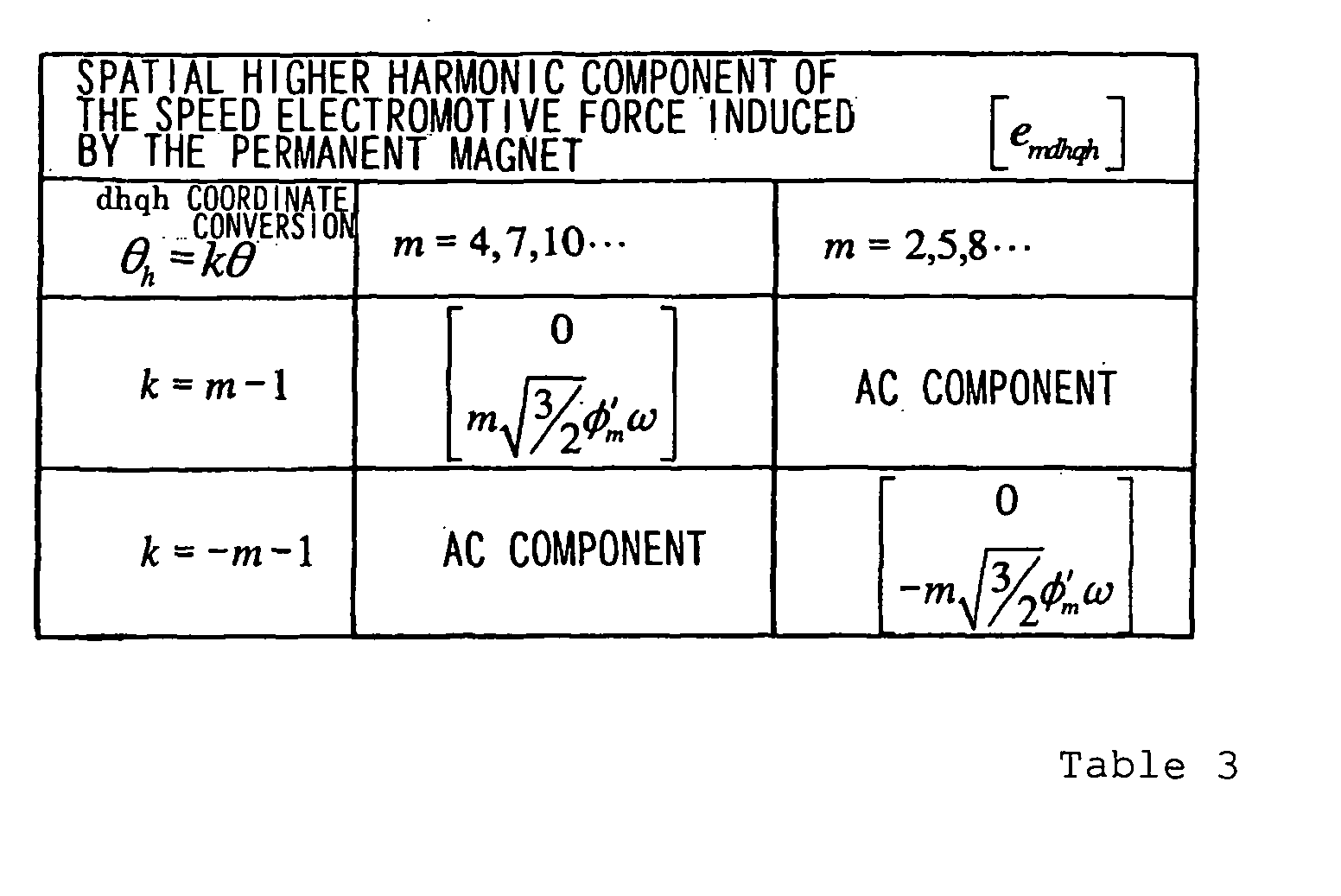
- the spatial higher harmonic component Xndhqh of the inductances are presented in Table 2, and the spatial higher harmonic component emdhqh of the speed electromotive forces induced by the magnet are presented in Table 3.
- Tables 2 and 3 indicate that the spatial higher harmonic component which is the primary cause of inducing the higher harmonic current can be expressed as a DC quantity.
- the terms pertaining to the speed electromotive forces include terms attributable to idh and iqh, terms attributable to id and iq and terms attributable to the higher harmonic component in the magnetic flux generated by the magnet. These speed electromotive forces constitute an external disturbance to the higher harmonic current control implemented in the dhqh coordinate system.
- a dhqh speed electromotive force compensator 18 is a feed-forward compensator which compensates for the adverse effect of the speed electromotive forces.
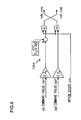
- FIG. 5 shows the structure adopted in the dhqh speed electromotive force compensator 18.
- the dhqh speed electromotive force compensator 18 calculates control voltages vdh_cmp and vqh_cmp based upon the d-axis current command value id*, the q-axis current command iq*, the dh-axis current command value idh*, the qh-axis current command value iqh*, the motor angular speed ⁇ e, the inductances L0 and L2 and the parameter of the higher harmonic component ⁇ 5' of the magnetic flux.
- Adders 19a and 19b respectively add the control voltages vdh and vqh determined at the dhqh-axis current controller 15 to the control voltages vdh_cmp and vqh_cmp having been calculated, and thus obtain dhqh control voltages vdh* and vqh*.
- a dhqh ⁇ 3-phase converter 16 converts the dhqh control voltages vdh* and vqh* to 3-phase AC voltages vu', vv' and vw'.
- Adders 17a, 17b and 17c add the 3-phase AC voltages vu', vv' and vw' respectively to the control voltages vu*, vv* and vw* obtained through the dq-axis current control and thus obtain voltage command values vu", vv" and vw" in correspondence to the individual phases.
- FIG. 6 shows the dh-axis current response and the qh-axis current response achieved by changing the qh current command value in steps through the higher harmonic current control implemented in the structure described above.
- a disturbance is observed both in the dh current and the qh current in the transient response.
- This disturbance occurs for the following reason.
- the d-axis current id and the q-axis current iq input to the dq-axis current controller 2 both contain the higher harmonic component. Since the dq-axis current controller 2 determines the control output so as to match the d-axis current id and the q-axis current iq respectively with the current command values id* and iq*, it tries to suppress the higher harmonic component. In other words, since the dq-axis current controller 2 interferes with the dhqh-axis current control, the conformity of the dhqh higher harmonic currents to the respective command values is adversely affected in the current transient response.
- the motor control apparatus in the first embodiment includes a dhqh ⁇ dq converter 20 and adders 21a and 21b.
- the dhqh ⁇ dq converter 20 converts the dh-axis current command value idh* and the qh-axis current command value iqh* respectively to values id_high* and iq_high* in the dq coordinate system.
- the coordinate conversion executed by the dhqh ⁇ dq converter 20 is expressed as in (10) below.
- the higher harmonic current command values id_high* and iq_high* resulting from the coordinate conversion are respectively added to the d-axis current command value id* and the q-axis current command value iq* by the adders 21a and 21b and thus, a d-axis current command value id1* and a q-axis current command value iq1* are determined (see expressions (11) and (12)).
- id1* id* + id_high*
- iq1* iq* + iq_high*
- the higher harmonic component values id_high* and iq_high* are respectively added to the d-axis current command value id* and the q-axis current command value iq* and then the d-axis current id and the q-axis current iq (feedback values) both containing the higher harmonic component are subtracted from the sums resulting from the addition, i.e., the d-axis current command value id1* and the q-axis current command value iq1*.
- the higher harmonic component contained in the d-axis current command id1* and the q-axis current command value iq1* is cancelled out by the higher harmonic component contained in the d-axis current feedback value id and the q-axis current feedback value iq respectively, and, as a result, it is possible to prevent any higher harmonic component from being input to the dq-axis current controller 2.
- the higher harmonic current is not suppressed through the control implemented by the dq-axis current controller 2, and the current control in the dq coordinate system and the current control in the dhqh coordinate system can be implemented completely independently of each other.
- the motor control apparatus in the first embodiment which achieves an improvement in the conformity of the higher harmonic current to the respective command values in the higher harmonic current control, reduces the extent of torque ripple and improves the motor efficiency when the higher harmonic current control is adopted in a vehicle that accelerates and decelerates over frequent intervals.
- the motor control apparatus in the first embodiment includes the non-interactive controller 3 and the adders 4a and 4b provided to compensate for any adverse effect of the d-axis and q-axis interference on the output vd and vq from the dq-axis current controller 2 based upon the d-axis current command value id* and the q-axis current command value iq* and the motor rotation speed ⁇ e and, as a result, the adverse effect of the d-axis and the q-axis interference is eliminated to further improve the response of the fundamental wave current control.
- the dhqh speed electromotive force compensator 18 and the adders 19a and 19b are provided to compensate for the adverse effect of the speed electromotive forces in the motor 11 on the output vdh and vqh from the dhqh current controller 15 based upon the d-axis current command value id* and the q-axis current command value iq*, the dh-axis current command value idh* and the qh-axis current command value iqh* and the motor rotation speed ⁇ e, the adverse effect of the motor speed electromotive forces is eliminated to further improve the response of the higher harmonic current control.
- FIG. 7 indicates that no disturbance causes in the current transient change and that a high level of conformity to the current command value is achieved.
- FIG. 8 is a block diagram of the structure adopted in the motor control apparatus in the second embodiment. It is to be noted that the same reference numerals are assigned to components identical to those shown in FIGS. 1 and 2 and the following explanation focuses on the differences from the first embodiment.
- the d-axis current command value id* and the q-axis current command value iq* as well as the motor angular speed ⁇ e are input to the non-interactive controller 3.
- the higher harmonic current command values id_high* and iq_high* calculated based upon expression (10) and the d-axis current command value id1* and the q-axis current command value iq1* respectively calculated based upon expressions (11) and (12) are input in addition to the motor angular speed ⁇ e to a non-interactive controller 3A.
- the non-interactive controller 3A calculates a d-axis compensating voltage vd_cmp and a q-axis compensating voltage vq_cmp through the following expressions (13) and (14).
- vd_cmp -Lq ⁇ e ⁇ iq1* - k ⁇ Ld ⁇ e ⁇ iq_high*
- vq_cmp ⁇ e ⁇ (Ld ⁇ id1* + ⁇ ) + k ⁇ Lq ⁇ e ⁇ id_high*
- FIG. 9 presents a structural example of the dhqh speed electromotive force compensator 18A in the second embodiment when the dhqh circuit equation of the motor is expressed as in expression (9).
- the current control in the dq coordinate system and the current control in the dhqh coordinate system can be implemented without allowing the dq-axis current controller 2 to interfere with the dhqh-axis current control.
- the conformity of the currents to the respective command values in the higher harmonic current control improves, and the extent of torque ripple can be reduced and the motor efficiency is improved even when the higher harmonic current control is adopted in a vehicle that accelerates and decelerates over frequent intervals.
- the motor control apparatus in the second embodiment includes the non-interactive controller 3A and the adders 4a and 4b provided to compensate for the adverse effect resulting from the d-axis and the q-axis interference on the output vd and vq from the dq-axis current controller 2 based upon the current command value id_high* and iq_high* in the dq coordinate systems obtained by converting the dh-axis current command value and the qh-axis current command value to values in the dq coordinate system, the d-axis and q-axis current command values id1* and iq1* both containing the higher harmonic component and the motor rotation speed ⁇ e, the adverse effect of the d-axis and the q-axis interference is eliminated to further improve the response of the fundamental wave current control.
- the dhqh speed electromotive force compensator 18a and the adders 19a and 19b provided to compensate for the adverse effect of the speed electromotive forces in the motor 11 on the output vdh and vqh from the dhqh-axis current controller 15 based upon the dh-axis current command value idh* and the qh-axis current command value iqh* and the motor rotation speed ⁇ e, the adverse effect of the motor speed electromotive forces is eliminated to further improve the response of the higher harmonic current control.
- FIG. 10 is a block diagram of the structure adopted in the motor control apparatus in the third embodiment. It is to be noted that the same reference numerals are assigned to components identical to those shown in FIGS. 1 and 2 and the following explanation focuses onthedifferences fromthe first embodiment.
- a d-axis current and a q-axis current (feedback values) that do not contain any higher harmonic component are generated by subtracting the higher harmonic component values id_high* and iq_high* (the output from the dhqh ⁇ dq converter 20) respectively from the d-axis current id and the q-axis current iq (feedback values) containing the higher harmonic component, and the d-axis current and the q-axis current are controlled based upon the control deviations relative to the fundamental wave component current command values id* and iq*.
- the higher harmonic current command values id_high* and iq_high* resulting from the conversion executed by the dhqh ⁇ dq converter 20 are input to subtractors 22a and 22b respectively.
- the subtractors 22a and 22b respectively subtract the higher harmonic current command values id_high* and iq_high* from the d-axis current id and the q-axis current iq both containing the higher harmonic component and thus obtain a d-axis current id1 and a q-axis current iq1 that do not contain any higher harmonic component (expressions (15) and (16)).
- id1 id - id_high*
- iq1 iq - iq_high*
- the subtractors 1a and 1b calculate the differences (current control deviations) (id* - id1) and (iq* - iq1) by subtracting the d-axis current id1 and the q-axis current iq1 (feedback values) constituted of the fundamental wave component alone respectively from the d-axis current command value id* and the q-axis current command value iq* containing the fundamental wave component alone.
- the differences thus calculated are input to the dq-axis current controller 2.
- the motor control apparatus in the third embodiment eliminates the higher harmonic component from the d-axis current id and the q-axis current iq (feedback values) input to the dq-axis current controller 2, and, as a result, the dq-axis current control and the dhqh-axis current control can be implemented completely independently of each other without allowing the dq-axis current controller 2 to interfere with the dhqh-axis current control.
- the conformity of the currents to the respective command values in the higher harmonic current control improves, and the extent of torque ripple can be reduced and the motor efficiency is improved even when the higher harmonic current control is adopted in a vehicle that accelerates and decelerates over frequent intervals.
- FIG. 11 is a block diagram of the structure adopted in the motor control apparatus in the fourth embodiment. It is to be noted that the same reference numerals are assigned to components identical to those shown in FIGS. 1 and 2 and the following explanation focuses on the differences from the first embodiment.
- the higher harmonic current extraction unit is constituted by using a high-pass filter 12A to extract the d-axis higher harmonic current id_high and the q-axis higher harmonic current iq_high. Then, subtractors 23a and 23b subtract the higher harmonic currents id_high and iq_high respectively from the d-axis current id and the q-axis current iq (feedback values) containing the higher harmonic component, thereby generating a d-axis current and a q-axis current that do not contain any higher harmonic component and are constituted of the fundamental wave component alone.
- the motor control apparatus in the fourth embodiment achieves an advantage equivalent to that realized by passing the d-axis current id and the q-axis current iq through a low-pass filter with a cutoff frequency equal to that of the high-pass filter 12A.
- the higher harmonic component can be excluded from the feedback values at the dq-axis current controller 2.
- the dq-axis current controller 2 is not allowed to interfere with the dhqh-axis current control and the current control in the dq coordinate system and the current control in the dhqh coordinate system can be implemented completely independently of each other.
- the conformity of the currents to the respective command values in the higher harmonic current control improves, and the extent of torque ripple can be reduced and the motor efficiency is improved even when the higher harmonic current control is adopted in a vehicle that accelerates and decelerates over frequent intervals.
- the motor control apparatus may be alternatively achieved by using a low-pass filter having a cutoff frequency equal to that of the high-pass filter 12A and using values obtained by passing the d-axis current id and the q-axis current iq through this low-pass filter as d-axis and q-axis current feedback values.
Landscapes
- Engineering & Computer Science (AREA)
- Power Engineering (AREA)
- Control Of Ac Motors In General (AREA)
- Control Of Motors That Do Not Use Commutators (AREA)
Abstract
Description


| DEGREE q IN THE 3-PHASE AC COORDINATE SYSTEM | DEGREE k IN THE dq COORDINATE SYSTEM |
| q=1,4,7, ··· | k = q-1 |
| q=2,5,8, ··· | k = -q-1 |




Claims (8)
- A motor control apparatus comprising:a fundamental wave current control means (2) for implementing feedback control on a fundamental wave component of a motor current flowing to a 3-phase AC motor (11) in a dq coordinate system rotating in synchronization with the rotation of the motor (11);a higher harmonic current control means (15) for implementing feedback control on a higher harmonic component of the motor current in a dhqh coordinate system rotating with a frequency which is an integral multiple of a frequency of the fundamental wave component of the motor current;a command value calculation means (5,16,17a,17b,17c) for calculating an AC voltage command value by adding an output from the fundamental wave current control means (2) to an output from the higher harmonic current control means (15) and outputs the AC voltage command value to a power conversion means (7) for generating a 3-phase AC voltage corresponding to the AC voltage command value; anda higher harmonic component elimination means (20,21a,21b) for eliminating the higher harmonic component of the motor current from a control deviation between a motor current feedback value and a fundamental wave current command value in the fundamental wave current control means (2).
- A motor control apparatus according to claim 1, wherein:the higher harmonic component eliminating means (20, 21a, 21b) converts higher harmonic current command values in the dhqh coordinate system to higher harmonic current command values in the dq coordinate system through coordinate conversion, and calculates a d-axis current command value and a q-axis current command value both containing the higher harmonic component by adding the higher harmonic current command values resulting from the coordinate conversion to fundamental wave current command values; andthe fundamental wave current control means (2) controls the fundamental wave component of the motor current so as to match motor current feedback values with the d-axis current command value and the q-axis current command value containing the higher harmonic component.
- A motor control apparatus according to claim 2, further comprising:a rotation speed detection means (8,10) for detecting a rotation speed of the motor (11);a non-interactive control means (3,3A,4a,4b) for compensating for an adverse effect caused by interference of the d-axis and the q-axis on the output from the fundamental wave current control means (2) based upon the fundamental wave current command values and the motor rotation speed; anda speed electromotive force compensation means (18,18A,19a,19b) for compensating for an adverse effect induced by a speed electromotive force in the motor on the output from the higher harmonic current control means (15) based upon the fundamental wave current command values, the higher harmonic current command values and the motor rotation speed.
- A motor control apparatus according to claim 2, further comprising:a rotation speed detection means (8,10) for detecting a rotation speed of the motor;a non-interactive control means (3,3A,4a,4b) for compensating for an adverse effect caused by interference of the d-axis and the q-axis on the output from the fundamental wave current control means based upon the higher harmonic current command values obtained through a conversion to the dq coordinate system, the d-axis current command value and q-axis current command value, both containing the higher harmonic component and the motor rotation speed; anda speed electromotive force compensation means (18,18A,19a,19b) for compensating for an adverse effect induced by a speed electromotive force in the motor on the output from the higher harmonic current control means (15) based upon the higher harmonic current command values and the motor rotation speed.
- Amotor control apparatus according to claim 1, wherein:the higher harmonic component elimination means (20, 21a, 21b) converts higher harmonic current command values in the dhqh coordinate system to higher harmonic current command values in the dq coordinate system through coordinate conversion and calculates motor current feedback values which are the fundamental wave component by subtracting the higher harmonic current command values resulting from the coordinate conversion from motor current feedback values in the fundamental wave current control means (2); andthe fundamental wave current control means (2) controls the fundamental wave component of the motor current so as to match the motor current feedback values which are the fundamental wave component with fundamental wave current command values.
- A motor control apparatus according to claim 1, wherein:the higher harmonic component elimination means (20, 21a, 21b) executes high-pass filter processing on the motor current feedback value and calculates the motor current feedback value which is the fundamental wave component by subtracting results of the high-pass filter processing from the motor current feedback value; andthe fundamental wave current control means (2) controls the fundamental wave component of the motor current so as to match the motor current feedback value which is the fundamental wave component with the fundamental wave current command value.
- A motor control apparatus according to claim 1, wherein:the higher harmonic component elimination means (20, 21a, 21b) executes low-pass filter processing on the motor current feedback value to calculate the motor current feedback value which is the fundamental wave component; andthe fundamental wave current control means (2) controls the fundamental wave component of the motor current so as to match the motor current feedback value which is the fundamental wave component with the fundamental wave current command value.
- A method for controlling a motor by employing circuits including a fundamental wave current control circuit (2) that implements feedback control on a fundamental wave component of a motor current in a dq coordinate system rotating in synchronizationwiththerotationofthemotor (11) andahigher harmonic current control circuit (15) that implements feedback control on a higher harmonic component of the motor current in a dhqh coordinate system rotating with a frequency which is an integral multiple of the frequency of the fundamental wave component of the motor current, comprising:eliminating the higher harmonic components of the motor current from a control deviation between a fundamental wave current command value and a motor current feedback value in the fundamental wave current control circuit (2);calculating an AC voltage command value by adding an output from the fundamental wave current control circuit (2) from which the higher harmonic component has been eliminated to an output from the higher harmonic current control circuit (15); andgenerating a 3-phase AC voltage corresponding to the AC voltage command value and applying the 3-phase AC voltage to a 3-phase AC motor (11).
Applications Claiming Priority (2)
| Application Number | Priority Date | Filing Date | Title |
|---|---|---|---|
| JP2003102480A JP3928575B2 (en) | 2003-04-07 | 2003-04-07 | Motor control device |
| JP2003102480 | 2003-04-07 |
Publications (3)
| Publication Number | Publication Date |
|---|---|
| EP1467478A2 true EP1467478A2 (en) | 2004-10-13 |
| EP1467478A3 EP1467478A3 (en) | 2005-12-14 |
| EP1467478B1 EP1467478B1 (en) | 2007-10-03 |
Family
ID=32866698
Family Applications (1)
| Application Number | Title | Priority Date | Filing Date |
|---|---|---|---|
| EP04008433A Expired - Lifetime EP1467478B1 (en) | 2003-04-07 | 2004-04-07 | Motor control apparatus and motor control method |
Country Status (4)
| Country | Link |
|---|---|
| US (1) | US7034493B2 (en) |
| EP (1) | EP1467478B1 (en) |
| JP (1) | JP3928575B2 (en) |
| DE (1) | DE602004009239T2 (en) |
Cited By (9)
| Publication number | Priority date | Publication date | Assignee | Title |
|---|---|---|---|---|
| EP2485388A1 (en) * | 2011-02-04 | 2012-08-08 | Siemens Aktiengesellschaft | Reduction of noise and vibrations of an electromechanical transducer by using a modified stator coil drive signal comprising harmonic components |
| FR2971377A1 (en) * | 2011-02-09 | 2012-08-10 | Renault Sa | METHOD AND DEVICE FOR CONTROLLING A RELUCTANCE ELECTRIC MACHINE |
| FR2979501A1 (en) * | 2011-08-31 | 2013-03-01 | Denso Corp | CONTROL APPARATUS FOR ELECTRIC ROTATING MACHINE |
| RU2479099C2 (en) * | 2008-03-19 | 2013-04-10 | Абб Швайц Аг | Method of converter operation and device for implementation thereof |
| FR2984635A1 (en) * | 2011-12-16 | 2013-06-21 | Continental Automotive Gmbh | CALCULATING A RESIDUAL CURRENT CURRENT RISE AT THE REAR AT THE DC INLET OF A MOTOR CONTROL DEVICE FOR A SYNCHRONOUS MACHINE |
| EP2206233A4 (en) * | 2007-10-15 | 2016-04-20 | Unico | BUS DISTURBANCE REGULATOR |
| EP2084586A4 (en) * | 2006-10-24 | 2017-08-16 | Unico, Inc. | Harmonic disturbance regulator |
| WO2019185299A1 (en) * | 2018-03-28 | 2019-10-03 | Robert Bosch Gmbh | Control device for an electric drive system, electric drive system, and method for controlling an electric drive system |
| WO2024074550A1 (en) * | 2022-10-05 | 2024-04-11 | Vitesco Technologies GmbH | Controlling an electric machine with a harmonic suppression using a counter signal in the vector space representation |
Families Citing this family (55)
| Publication number | Priority date | Publication date | Assignee | Title |
|---|---|---|---|---|
| JP3783695B2 (en) * | 2003-03-20 | 2006-06-07 | 日産自動車株式会社 | Motor control device |
| JP2005328691A (en) * | 2004-04-15 | 2005-11-24 | Denso Corp | Motor control device |
| US7813904B2 (en) | 2004-11-17 | 2010-10-12 | Toyota Technical Development Corporation | Method, apparatus, and computer readable medium based program for simulating an alternate current electric motor using a motor model |
| KR100655702B1 (en) * | 2004-12-20 | 2006-12-11 | 현대자동차주식회사 | Permanent Magnet Synchronous Motor Control Method |
| JP4674516B2 (en) * | 2005-09-27 | 2011-04-20 | 株式会社デンソー | Method for estimating magnetic pole position of synchronous motor |
| JP5167631B2 (en) * | 2006-11-30 | 2013-03-21 | 株式会社デンソー | Motor control method and motor control apparatus using the same |
| US7642737B2 (en) * | 2007-03-13 | 2010-01-05 | Gm Global Technology Operations, Inc. | Anti-windup control for a current regulator of a pulse width modulation inverter |
| US7768220B2 (en) | 2008-04-24 | 2010-08-03 | Gm Global Technology Operations, Inc. | Harmonic torque ripple reduction at low motor speeds |
| JP4751435B2 (en) * | 2008-10-09 | 2011-08-17 | 株式会社東芝 | Motor magnetic pole position detection device, motor control device, motor drive system and washing machine |
| JP5558752B2 (en) * | 2009-07-30 | 2014-07-23 | 日立オートモティブシステムズ株式会社 | Power converter |
| GB201006404D0 (en) | 2010-04-16 | 2010-06-02 | Trw Ltd | Motor control with voltage harmonic shaping |
| WO2011135694A1 (en) * | 2010-04-28 | 2011-11-03 | 株式会社 日立製作所 | Power conversion device |
| JP5589556B2 (en) * | 2010-05-20 | 2014-09-17 | 株式会社デンソー | Rotating machine control device |
| IT1400456B1 (en) * | 2010-06-04 | 2013-05-31 | St Microelectronics Srl | METHOD OF CONTROL OF A SYNCHRONOUS THREE-PHASE MOTOR WITH PERMANENT MAGNETS TO REDUCE NOISE AND RELATIVE CONTROL DEVICE |
| JP5481286B2 (en) * | 2010-06-30 | 2014-04-23 | 日立オートモティブシステムズ株式会社 | Power conversion system and power conversion device |
| DK2487780T3 (en) * | 2011-02-14 | 2020-03-02 | Siemens Ag | Control unit for a power converter and method of operation thereof |
| JP5686026B2 (en) * | 2011-04-07 | 2015-03-18 | 株式会社デンソー | Rotating machine control device |
| US20120274251A1 (en) | 2011-04-29 | 2012-11-01 | Danfoss Drives A/S | Harmonic noise reduction |
| CN102244497B (en) * | 2011-07-08 | 2013-05-08 | 大禹电气科技股份有限公司 | Frequency conversion control method and device |
| CN102255588B (en) * | 2011-07-08 | 2013-10-16 | 大禹电气科技股份有限公司 | Variable-frequency speed regulating device |
| CN102244496B (en) * | 2011-07-08 | 2013-09-04 | 大禹电气科技股份有限公司 | Variable frequency speed-adjusting system for motor |
| EP2552012A1 (en) * | 2011-07-27 | 2013-01-30 | Siemens Aktiengesellschaft | Reduction of noise and vibrations of an electromechanical transducer by using a modified stator coil drive signal comprising harmonic components |
| JP5964613B2 (en) * | 2012-03-05 | 2016-08-03 | 株式会社ダイヘン | Control circuit for motor drive inverter circuit and inverter device provided with the control circuit |
| US20130119900A1 (en) * | 2011-11-10 | 2013-05-16 | Ford Global Technologies, Llc | Motor torque ripple compensation |
| CN103858334B (en) * | 2011-11-17 | 2016-09-07 | 三菱电机株式会社 | AC rotary motor controls device and possesses the electric power-assisted steering apparatus of AC rotary motor control device |
| WO2013084461A1 (en) * | 2011-12-09 | 2013-06-13 | パナソニック株式会社 | Electric motor control device |
| TWI439041B (en) | 2011-12-19 | 2014-05-21 | 財團法人工業技術研究院 | Permanent magnet synchronous motor driving method and device |
| US8924082B2 (en) | 2012-03-30 | 2014-12-30 | Steering Solutions Ip Holding Corporation | System and method for controlling a motor |
| US8729838B2 (en) * | 2012-05-18 | 2014-05-20 | Hamilton Sundstrand Corporation | Current control for an electric actuator |
| JP5672278B2 (en) * | 2012-08-29 | 2015-02-18 | 株式会社デンソー | Control device for three-phase rotating machine |
| JP6143875B2 (en) * | 2012-11-14 | 2017-06-07 | ポスコエナジー株式会社Posco Energy Co.,Ltd. | Inverter ripple, offset compensation apparatus and method |
| JP5585643B2 (en) * | 2012-12-14 | 2014-09-10 | ダイキン工業株式会社 | Active filter control device |
| US9663139B2 (en) | 2013-02-26 | 2017-05-30 | Steering Solutions Ip Holding Corporation | Electric motor feedforward control utilizing dynamic motor model |
| JP6084863B2 (en) * | 2013-02-28 | 2017-02-22 | 川崎重工業株式会社 | Power converter for grid connection |
| US9136785B2 (en) * | 2013-03-12 | 2015-09-15 | Steering Solutions Ip Holding Corporation | Motor control system to compensate for torque ripple |
| US9143081B2 (en) | 2013-03-14 | 2015-09-22 | Steering Solutions Ip Holding Corporation | Motor control system having bandwidth compensation |
| US10336212B2 (en) * | 2013-11-27 | 2019-07-02 | Ford Global Technologies, Llc | Torque monitoring system and method |
| US10389289B2 (en) | 2014-02-06 | 2019-08-20 | Steering Solutions Ip Holding Corporation | Generating motor control reference signal with control voltage budget |
| US10003285B2 (en) | 2014-06-23 | 2018-06-19 | Steering Solutions Ip Holding Corporation | Decoupling current control utilizing direct plant modification in electric power steering system |
| WO2016000215A1 (en) * | 2014-07-01 | 2016-01-07 | 广东美芝制冷设备有限公司 | Method for suppressing fluctuations in speed, control device and compressor control system |
| JP6221981B2 (en) * | 2014-07-25 | 2017-11-01 | 株式会社デンソー | Control device for rotating electrical machine |
| US9419553B2 (en) * | 2014-07-25 | 2016-08-16 | Denso Corporation | Apparatus for controlling rotary machine |
| US9809247B2 (en) | 2015-01-30 | 2017-11-07 | Steering Solutions Ip Holding Corporation | Motor control current sensor loss of assist mitigation for electric power steering |
| JP6512018B2 (en) * | 2015-07-29 | 2019-05-15 | 株式会社デンソー | Motor control device |
| KR101664739B1 (en) * | 2015-08-31 | 2016-10-12 | 현대자동차주식회사 | Control method and system of motor |
| JP2017127066A (en) * | 2016-01-12 | 2017-07-20 | 日本精工株式会社 | Motor control device and electric power steering device equipped with the same |
| JP2017153226A (en) * | 2016-02-24 | 2017-08-31 | 株式会社デンソー | Control device for AC motor |
| US10135368B2 (en) | 2016-10-01 | 2018-11-20 | Steering Solutions Ip Holding Corporation | Torque ripple cancellation algorithm involving supply voltage limit constraint |
| KR101878090B1 (en) * | 2017-01-04 | 2018-07-16 | 현대자동차주식회사 | Method and system for controlling motor |
| JP6848622B2 (en) * | 2017-04-05 | 2021-03-24 | 富士電機株式会社 | Power converter and its control device |
| JP6629893B2 (en) | 2018-02-05 | 2020-01-15 | ファナック株式会社 | Motor drive device for estimating stray capacitance |
| DK3696969T3 (en) * | 2019-02-13 | 2022-05-02 | Siemens Gamesa Renewable Energy As | Harmonious control of a converter |
| TWI723605B (en) * | 2019-10-31 | 2021-04-01 | 國立中央大學 | Motor control system and control method of maximum power factor controller thereof |
| JP7374813B2 (en) * | 2020-02-28 | 2023-11-07 | サンデン株式会社 | motor control device |
| DE102023211453B4 (en) * | 2023-11-17 | 2025-10-16 | Schaeffler Technologies AG & Co. KG | Control of an electrical machine with harmonic suppression in several quantities by counter signal generation in space vector representation |
Family Cites Families (7)
| Publication number | Priority date | Publication date | Assignee | Title |
|---|---|---|---|---|
| EP1211798B1 (en) * | 2000-11-22 | 2018-01-10 | Nissan Motor Co., Ltd. | Motor control apparatus and motor control method |
| JP3809783B2 (en) | 2000-11-22 | 2006-08-16 | 日産自動車株式会社 | Motor control device |
| JP3627683B2 (en) | 2001-06-29 | 2005-03-09 | 日産自動車株式会社 | Motor control device |
| JP3582505B2 (en) | 2001-09-10 | 2004-10-27 | 日産自動車株式会社 | Motor control device |
| US6777907B2 (en) * | 2001-11-06 | 2004-08-17 | International Rectifier Corporation | Current ripple reduction by harmonic current regulation |
| JP3722048B2 (en) * | 2001-11-15 | 2005-11-30 | 日産自動車株式会社 | Motor control device |
| WO2004055967A1 (en) * | 2002-10-17 | 2004-07-01 | Denso Corporation | Ac rotary electric machine magnetic noise reduction method, motor control device and ac rotary electric machine using the same |
-
2003
- 2003-04-07 JP JP2003102480A patent/JP3928575B2/en not_active Expired - Fee Related
-
2004
- 2004-04-01 US US10/814,237 patent/US7034493B2/en not_active Expired - Fee Related
- 2004-04-07 EP EP04008433A patent/EP1467478B1/en not_active Expired - Lifetime
- 2004-04-07 DE DE602004009239T patent/DE602004009239T2/en not_active Expired - Lifetime
Cited By (11)
| Publication number | Priority date | Publication date | Assignee | Title |
|---|---|---|---|---|
| EP2084586A4 (en) * | 2006-10-24 | 2017-08-16 | Unico, Inc. | Harmonic disturbance regulator |
| EP2206233A4 (en) * | 2007-10-15 | 2016-04-20 | Unico | BUS DISTURBANCE REGULATOR |
| RU2479099C2 (en) * | 2008-03-19 | 2013-04-10 | Абб Швайц Аг | Method of converter operation and device for implementation thereof |
| EP2485388A1 (en) * | 2011-02-04 | 2012-08-08 | Siemens Aktiengesellschaft | Reduction of noise and vibrations of an electromechanical transducer by using a modified stator coil drive signal comprising harmonic components |
| FR2971377A1 (en) * | 2011-02-09 | 2012-08-10 | Renault Sa | METHOD AND DEVICE FOR CONTROLLING A RELUCTANCE ELECTRIC MACHINE |
| WO2012107665A3 (en) * | 2011-02-09 | 2013-07-18 | Renault S.A.S. | Method and device for controlling a reluctance electric machine |
| CN103354974A (en) * | 2011-02-09 | 2013-10-16 | 雷诺股份公司 | Method and apparatus for controlling a reluctance motor |
| FR2979501A1 (en) * | 2011-08-31 | 2013-03-01 | Denso Corp | CONTROL APPARATUS FOR ELECTRIC ROTATING MACHINE |
| FR2984635A1 (en) * | 2011-12-16 | 2013-06-21 | Continental Automotive Gmbh | CALCULATING A RESIDUAL CURRENT CURRENT RISE AT THE REAR AT THE DC INLET OF A MOTOR CONTROL DEVICE FOR A SYNCHRONOUS MACHINE |
| WO2019185299A1 (en) * | 2018-03-28 | 2019-10-03 | Robert Bosch Gmbh | Control device for an electric drive system, electric drive system, and method for controlling an electric drive system |
| WO2024074550A1 (en) * | 2022-10-05 | 2024-04-11 | Vitesco Technologies GmbH | Controlling an electric machine with a harmonic suppression using a counter signal in the vector space representation |
Also Published As
| Publication number | Publication date |
|---|---|
| JP2004312864A (en) | 2004-11-04 |
| EP1467478A3 (en) | 2005-12-14 |
| JP3928575B2 (en) | 2007-06-13 |
| US7034493B2 (en) | 2006-04-25 |
| EP1467478B1 (en) | 2007-10-03 |
| US20040195993A1 (en) | 2004-10-07 |
| DE602004009239D1 (en) | 2007-11-15 |
| DE602004009239T2 (en) | 2008-01-17 |
Similar Documents
| Publication | Publication Date | Title |
|---|---|---|
| EP1467478B1 (en) | Motor control apparatus and motor control method | |
| KR100655702B1 (en) | Permanent Magnet Synchronous Motor Control Method | |
| US6642689B2 (en) | Control apparatus for power converter | |
| JP4578568B2 (en) | AC motor control device | |
| JP4687846B2 (en) | Magnetic pole position estimation method and control apparatus for synchronous motor | |
| JP3582505B2 (en) | Motor control device | |
| JP4019842B2 (en) | Motor control device | |
| EP2012425B1 (en) | Synchronous motor control device and synchronous motor control method | |
| EP1492224A1 (en) | Sensorless controller of ac motor and control method | |
| JP3809783B2 (en) | Motor control device | |
| JP2008295200A (en) | Synchronous motor control device and synchronous motor control optimization method | |
| JP2012228083A (en) | Controller for ac motor | |
| JP7158573B2 (en) | POWER CONVERSION DEVICE AND ELECTRIC VEHICLE SYSTEM INCLUDING THE SAME | |
| JP4154149B2 (en) | Vector control inverter device | |
| Imai et al. | Extended EMF observer of dual three-phase permanent magnet synchronous motor operable in overmodulation drive | |
| JP3914107B2 (en) | DC brushless motor control device | |
| JP4596906B2 (en) | Electric motor control device | |
| JP2009044908A (en) | Rotation angle estimation device and drive system for rotating machine | |
| JP3637209B2 (en) | Power converter using speed sensorless vector control | |
| JPH10271900A (en) | Power converter | |
| US12143038B2 (en) | Rotary machine control device | |
| JP2022144060A (en) | Synchronous machine control device, synchronous machine control method, and electric car | |
| JP4526628B2 (en) | AC motor control device | |
| JP7833330B2 (en) | Motor control device and electric vehicle | |
| JP2004023804A (en) | Motor control device |
Legal Events
| Date | Code | Title | Description |
|---|---|---|---|
| PUAI | Public reference made under article 153(3) epc to a published international application that has entered the european phase |
Free format text: ORIGINAL CODE: 0009012 |
|
| 17P | Request for examination filed |
Effective date: 20040407 |
|
| AK | Designated contracting states |
Kind code of ref document: A2 Designated state(s): AT BE BG CH CY CZ DE DK EE ES FI FR GB GR HU IE IT LI LU MC NL PL PT RO SE SI SK TR |
|
| AX | Request for extension of the european patent |
Extension state: AL HR LT LV MK |
|
| PUAL | Search report despatched |
Free format text: ORIGINAL CODE: 0009013 |
|
| AK | Designated contracting states |
Kind code of ref document: A3 Designated state(s): AT BE BG CH CY CZ DE DK EE ES FI FR GB GR HU IE IT LI LU MC NL PL PT RO SE SI SK TR |
|
| AX | Request for extension of the european patent |
Extension state: AL HR LT LV MK |
|
| RIC1 | Information provided on ipc code assigned before grant |
Ipc: 7H 02P 6/10 A |
|
| AKX | Designation fees paid |
Designated state(s): DE FR GB |
|
| GRAP | Despatch of communication of intention to grant a patent |
Free format text: ORIGINAL CODE: EPIDOSNIGR1 |
|
| GRAS | Grant fee paid |
Free format text: ORIGINAL CODE: EPIDOSNIGR3 |
|
| GRAA | (expected) grant |
Free format text: ORIGINAL CODE: 0009210 |
|
| AK | Designated contracting states |
Kind code of ref document: B1 Designated state(s): DE FR GB |
|
| REG | Reference to a national code |
Ref country code: GB Ref legal event code: FG4D |
|
| REF | Corresponds to: |
Ref document number: 602004009239 Country of ref document: DE Date of ref document: 20071115 Kind code of ref document: P |
|
| ET | Fr: translation filed | ||
| PLBE | No opposition filed within time limit |
Free format text: ORIGINAL CODE: 0009261 |
|
| STAA | Information on the status of an ep patent application or granted ep patent |
Free format text: STATUS: NO OPPOSITION FILED WITHIN TIME LIMIT |
|
| 26N | No opposition filed |
Effective date: 20080704 |
|
| REG | Reference to a national code |
Ref country code: FR Ref legal event code: PLFP Year of fee payment: 12 |
|
| PGFP | Annual fee paid to national office [announced via postgrant information from national office to epo] |
Ref country code: DE Payment date: 20150331 Year of fee payment: 12 Ref country code: GB Payment date: 20150401 Year of fee payment: 12 |
|
| PGFP | Annual fee paid to national office [announced via postgrant information from national office to epo] |
Ref country code: FR Payment date: 20150408 Year of fee payment: 12 |
|
| REG | Reference to a national code |
Ref country code: DE Ref legal event code: R119 Ref document number: 602004009239 Country of ref document: DE |
|
| GBPC | Gb: european patent ceased through non-payment of renewal fee |
Effective date: 20160407 |
|
| REG | Reference to a national code |
Ref country code: FR Ref legal event code: ST Effective date: 20161230 |
|
| PG25 | Lapsed in a contracting state [announced via postgrant information from national office to epo] |
Ref country code: FR Free format text: LAPSE BECAUSE OF NON-PAYMENT OF DUE FEES Effective date: 20160502 Ref country code: GB Free format text: LAPSE BECAUSE OF NON-PAYMENT OF DUE FEES Effective date: 20160407 Ref country code: DE Free format text: LAPSE BECAUSE OF NON-PAYMENT OF DUE FEES Effective date: 20161101 |