EP1467436A2 - Autoantennenvorrichtung, Autoantennensystem und Kommunikationssystem, das besagte Antennenvorrichtung verwendet - Google Patents
Autoantennenvorrichtung, Autoantennensystem und Kommunikationssystem, das besagte Antennenvorrichtung verwendet Download PDFInfo
- Publication number
- EP1467436A2 EP1467436A2 EP04008430A EP04008430A EP1467436A2 EP 1467436 A2 EP1467436 A2 EP 1467436A2 EP 04008430 A EP04008430 A EP 04008430A EP 04008430 A EP04008430 A EP 04008430A EP 1467436 A2 EP1467436 A2 EP 1467436A2
- Authority
- EP
- European Patent Office
- Prior art keywords
- vehicle
- antenna device
- core
- coil
- vehicle antenna
- Prior art date
- Legal status (The legal status is an assumption and is not a legal conclusion. Google has not performed a legal analysis and makes no representation as to the accuracy of the status listed.)
- Ceased
Links
Images


Classifications
-
- H—ELECTRICITY
- H01—ELECTRIC ELEMENTS
- H01Q—ANTENNAS, i.e. RADIO AERIALS
- H01Q7/00—Loop antennas with a substantially uniform current distribution around the loop and having a directional radiation pattern in a plane perpendicular to the plane of the loop
- H01Q7/06—Loop antennas with a substantially uniform current distribution around the loop and having a directional radiation pattern in a plane perpendicular to the plane of the loop with core of ferromagnetic material
- H01Q7/08—Ferrite rod or like elongated core
-
- B—PERFORMING OPERATIONS; TRANSPORTING
- B60—VEHICLES IN GENERAL
- B60R—VEHICLES, VEHICLE FITTINGS, OR VEHICLE PARTS, NOT OTHERWISE PROVIDED FOR
- B60R25/00—Fittings or systems for preventing or indicating unauthorised use or theft of vehicles
- B60R25/20—Means to switch the anti-theft system on or off
- B60R25/24—Means to switch the anti-theft system on or off using electronic identifiers containing a code not memorised by the user
-
- H—ELECTRICITY
- H01—ELECTRIC ELEMENTS
- H01Q—ANTENNAS, i.e. RADIO AERIALS
- H01Q1/00—Details of, or arrangements associated with, antennas
- H01Q1/27—Adaptation for use in or on movable bodies
- H01Q1/32—Adaptation for use in or on road or rail vehicles
- H01Q1/3208—Adaptation for use in or on road or rail vehicles characterised by the application wherein the antenna is used
- H01Q1/3233—Adaptation for use in or on road or rail vehicles characterised by the application wherein the antenna is used particular used as part of a sensor or in a security system, e.g. for automotive radar, navigation systems
- H01Q1/3241—Adaptation for use in or on road or rail vehicles characterised by the application wherein the antenna is used particular used as part of a sensor or in a security system, e.g. for automotive radar, navigation systems particular used in keyless entry systems
-
- H—ELECTRICITY
- H01—ELECTRIC ELEMENTS
- H01Q—ANTENNAS, i.e. RADIO AERIALS
- H01Q1/00—Details of, or arrangements associated with, antennas
- H01Q1/27—Adaptation for use in or on movable bodies
- H01Q1/32—Adaptation for use in or on road or rail vehicles
- H01Q1/325—Adaptation for use in or on road or rail vehicles characterised by the location of the antenna on the vehicle
- H01Q1/3266—Adaptation for use in or on road or rail vehicles characterised by the location of the antenna on the vehicle using the mirror of the vehicle
-
- B—PERFORMING OPERATIONS; TRANSPORTING
- B60—VEHICLES IN GENERAL
- B60R—VEHICLES, VEHICLE FITTINGS, OR VEHICLE PARTS, NOT OTHERWISE PROVIDED FOR
- B60R1/00—Optical viewing arrangements; Real-time viewing arrangements for drivers or passengers using optical image capturing systems, e.g. cameras or video systems specially adapted for use in or on vehicles
- B60R1/12—Mirror assemblies combined with other articles, e.g. clocks
- B60R2001/1261—Mirror assemblies combined with other articles, e.g. clocks with antennae
Definitions
- the present invention relates to an antenna device installed on a vehicle for use in the keyless entry system, with which system the vehicle door can be locked/unlocked by a remote control operation.
- the invention discloses a vehicle antenna system and a communication system containing the antenna device, too.
- the keyless entry system which locks/unlocks vehicle door by a remote control operation has become popular, and the design of vehicles has become diversified. There are increasing demands for a compact antenna device that can be installed easily on such sorts of vehicles.
- a conventional antenna device for vehicles is described in the following, referring to FIG. 7 and FIG. 8.
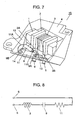
- FIG. 7 is a perspective view showing the key part of a conventional vehicle antenna device.
- core 1 is made of a ferrite material.
- Bobbin 2 has a blank at the central portion, and the holding portion is made of a dielectric resin. Outer surface of bobbin 2 is wound around with a linear conductor to form coil 3. The central portion of bobbin 2 is penetrated by core 1.
- Case 4 is for housing bobbin 2 and other items. Case 4 is provided with lead terminals 5, 6 and relay elements 13, 14, which are insert-molded.
- Relay element 13 is electrically connected with lead 3A, which being one of the two ends of coil 3, by soldering or the like means; while lead terminal 5 is likewise connected with lead 3B, which being the other end of coil 3.
- Relay element 13 is electrically connected also with lead 9A, which being one of the two ends of capacitor 9, while the other end of capacitor 9, or lead 9B, is connected with relay element 14.
- lead 11A which being one of the two ends of resistor 11, is electrically connected with relay element 14, while the other end, or lead 11B, is connected with lead terminal 6.
- FIG. 8 As shown in a circuit diagram, FIG. 8, coil 3, capacitor 9 and resistor 11 are connected in series. Both ends of which serially connected line are connected with lead terminals 5 and 6, respectively. Vehicle antenna device 15 has such configuration.
- Lead terminals 5 and 6 are electrically coupled with a control circuit (not shown) built in a vehicle body.
- the control circuit and vehicle antenna device 15 integrally constitute a serial resonance circuit.
- Japanese Patent Laid-Open Application No. 2001- 345615 represents a known prior art information relevant to the present invention.
- the conventional vehicle antenna device and a vehicle antenna system and a communication system containing the antenna device are described below referring to FIG. 9.
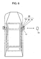
- FIG. 9 is a drawing used to show the concept of a conventional communication system.
- vehicle antenna device 15 transmits/receives electromagnetic waves for communication with a third party;
- fixing portion 16 is for installing a mirror close to the door at driver's seat, and at passenger seat.
- Movable portion 17 is for holding a mirror, and foldable.
- Vehicle antenna device 15 is housed in movable portion 17; vehicle antenna device 15 and movable portion 17 integrally form vehicle antenna system 18.
- Card 19 is proprietary to a vehicle equipped with vehicle antenna system 18 for communication.
- a communication system is structured by a combination of card 19, vehicle antenna system 18 and a control circuit (not shown) connected to vehicle antenna system 18.
- control circuit regularly outputs a signal to card 19 held by a vehicle driver, requesting to respondwith the ID code.
- Vehicle antenna device 15 transmits the signal after converting it into electromagnetic wave of a certain specific resonance frequency.
- card 19 When a vehicle driver holding card 19 makes access to be close to the vehicle and card 19 receives the electromagnetic wave, card 19 transmits ID code signal after converting it into electromagnetic wave.
- the vehicle door is automatically unlocked. In a case when it is not recognized to be true, or failed to receive the ID code sent from a vehicle driver going away from the vehicle, the door is automatically locked.
- Japanese Patent Laid-Open Application No. 2002-30844 is a known prior art information relevant to the present invention.
- the present invention offers an antenna device for installation on vehicles for receiving electromagnetic wave airing between the vehicle and outside the vehicle.
- the antenna device includes a core made of a magnetic material, a coil formed by a linear conductor wound around the core, a case made of a dielectric resin material for housing the core and the coil, and a dielectric resin filling the space within the case excluding the core, holding portion and the coil.
- FIG. 1 is a perspective view showing the key part of a vehicle antenna device in accordance with a first exemplary embodiment of the present invention.
- core 21 is made of ferrite or the like magnetic material
- holding portion 22 is formed of a film sheet of polyethylene terephthalate or the like dielectric material. Core 21 is wound around by holding portion 22 for at least one turn.
- Coil 23 is formed by a linear conductor wound around the outer surface of holding portion 22.
- Preferred thickness of the film sheet for holding portion 22 is 0.025 - 0.05 mm; it is because of easy availability and easy winding operation around core 21.
- Thinner holding portion 22 provides the closer attachment of coil 23 to core 21. Therefore, the thinner film sheet results in the greater magnetic permeability, and number of turns of the linear conductor can be decreased for forming coil 23.
- Case 24 for housing coil 23, core 21, etc. is provided with relay elements 33, 34 and lead terminals 25, 26 formed of conductor sheet, which being insert-molded.
- Core 21 is disposed in case 24 so that there is a distance of at least 5 mm between the outer surface of core 21 and the outer surface of case 24.
- Lead 23A which being one of the two ends of coil 23, is electrically connected with relay element 33 by soldering or the like means; while lead 23B, or the other end of coil 23, is likewise connected with lead terminal 25.
- Lead 29A which being one of the two ends of capacitor 29, is electrically connected with relay element 33; while lead 29B, or the other end, with relay element 34.
- lead 31A which being one of the two ends of resistor 31, is electrically connected with relay element 34; while lead 31B, or the other end, with lead terminal 26.
- resin 32 which is silicone or the like flexible dielectric material.
- capacitor 29 and resistor 31 are connected in series. The two ends of the serially connected line are provided with lead terminals 25 and 26, and vehicle antenna device 35 is completed.
- Lead terminals 25 and 26 are electrically connected to a control circuit (not shown) built in a vehicle body, so that the control circuit and vehicle antenna device 35 integrally form a serial resonance circuit.
- vehicle antenna device 35 is mounted within a vehicle mirror disposed adjacent to the door at driver's seat, and that at passenger seat; in the vehicle mirror's installation premises 36 used for installing it on a vehicle body.
- Installation premises 36 remains fixed unmoved even when mirror portion 37 is revolved.
- Material of the vehicle body corresponding to installation premises 36 is not a metal, but it is polybutylene terephthalate or the like dielectric resin material.
- vehicle antenna device 35 when a vehicle card for keyless entry system makes access to the vehicle, vehicle antenna device 35 receives electromagnetic wave of a certain predetermined resonance frequency specific to the vehicle card, and then the electromagnetic wave is converted into an electric signal, and delivered to the control circuit.
- the control circuit Upon detecting the signal, the control circuit outputs a signal requesting to send an ID code proprietary to the vehicle card. Vehicle antenna device 35 transmits electromagnetic wave representing the signal.
- the vehicle card Upon receiving the electromagnetic wave, the vehicle card transmits an ID code signal after converting it into electromagnetic wave.
- antenna device 35 When antenna device 35 receives the electromagnetic wave and the control circuit recognizes that the incoming ID code is true, door of the vehicle is unlocked automatically. When the code is not recognized to be true, or it failed to receive an ID code, the door is automatically locked.
- directivity 40 designates a scope of electromagnetic wave whose energy strength is higher than a certain specific level.
- the scope spreads in a spherical shape around the vicinity of the right and the left ends of core 21.
- the core is shaped at the vicinity of the right end along sloped planes. However, it is not limited to a sloped plane, but the core may be shaped along stepped planes for modifying directivity 40.
- the left end area may be made to be different in relation to the right end counterpart for the purpose of modifying directivity 40.
- Directivity 40 can be modified in this way, because density of magnetic lines at the vicinity of the left end, or the right end, of core 21 can be changed by shaping core 21 so that it has different area at the vicinity of the left end, or the right end, in relation to cross sectional area at the rest portions.
- vehicle antenna device 35 has been formed with core 21 of magnetic material, holding portion 22 provided by winding a dielectric film sheet around core 21, coil 23 formed with a linear conductor wound around holding portion 22, case 24 made of dielectric resin for housing core 21, holding portion 22 and coil 23, and flexible dielectric resin 32 filling the space within case 24 excluding core 21, holding portion 22 and coil 23. Since holding portion 22 is provided by winding a film sheet around core 21, there is no need of providing a gap between holding portion 22 and core 21. Another advantage of this structure is that holding portion 22 can be formed in a thin contour. Thus the present invention offers vehicle antenna device 35 that is compact in the overall size and easy to mount on a vehicle body.
- the eddy current loss is a heat loss with electromagnetic wave due to eddy current in metal portion caused by magnetic flux which is generated by core 21.
- the eddy current loss is a heat loss with electromagnetic wave due to eddy current in metal portion caused by magnetic flux which is generated by core 21.
- vehicle antenna device 35 is mounted within a vehicle mirror at the installation premises which is used for installing the mirror on a vehicle, and communication with a third party is conducted via vehicle antenna device 35. Since the installation premises stays fixed even when the mirror is revolved, the range of transmission/reception remains unchanged before and after the revolution of a mirror. Thus the steady range of communication is maintained unchanged.
- the density of magnetic lines at the vicinity of the left end, or the right end, of core 21 can be changed by making the cross sectional area at the vicinity of the left end, or the right end, to be different in relation to that in the remaining portion, the directivity can be modified with ease.
- thickness of holding portion 22 is not thicker than 1 mm, and the thinner the greater with a rate of magnetic permeation, number of windings of linear conductor can be reduced.
- the present invention offers an inexpensive vehicle antenna device that is easy to assemble.
- core 21 in the above description is provided with holding portion 22, coil 23 can be wound immediately on core 21 in a case where core 21 is made of an insulating magnetic material.
- the present invention can be implemented in this way either.
- vehicle antenna device 35 is mounted within a vehicle mirror disposed adjacent to the door at driver's seat, and that at passenger seat, at installation premises 36 which is used for installing the mirror on a vehicle body.
- the antenna device may be mounted within a vehicle mirror disposed above the front wheel, at installation premises which is used for installing the mirror on vehicle body above the front wheel.
- the present invention can be embodied in a unidirectional communication system.
- vehicle key transmits electromagnetic wave representing ID code proprietary to the key
- vehicle antenna device 35 receives it to lock/unlock the vehicle door.
- the present invention offers a substantial advantage that it implements a compact and easy-to-mount vehicle antenna device, and a communication system containing the antenna device.
- FIG. 5 is the drawing used to show the concept of a communication system in accordance with a second exemplary embodiment of the present invention.
- vehicle antenna device 35 transmits/receives electromagnetic waves for communication with a third party
- fixing portion 16 is for holding a vehicle mirror (hereinafter referred to as mirror) close to the door at driver's seat, and at passenger seat, which portion is formed with polybutylene terephthalete or the like dielectric resin material.
- Vehicle antenna device 35 is housed in fixing portion 16, and fixing portion 16 and vehicle antenna device 35 integrally form vehicle antenna system 20.
- Card 19 which is proprietary to a certain specific vehicle is used to communicate with vehicle antenna system 20.
- Card 19 vehicle antenna system 20 and a control circuit (not shown) connected with vehicle antenna system 20 integrally constitute a communication system.
- fixing portion 16 for holding a mirror stays fixed unmoved even after movable portion 17 holding the mirror is folded by a vehicle driver.
- Vehicle antenna device 35 has been housed within fixing portion 16.
- vehicle antenna device 35 there exists more amount of magnetic flux at a place closer to end face of core 21. So, the amount of heat loss with electromagnetic wave due to eddy current in metal portion which is caused by the magnetic flux is greater in a region closer to the end face.
- vehicle antenna device 35 is disposed within the inside of fixing portion 16 in accordance with the present invention, it is easier to prevent the growing heat loss with electromagnetic waves due to eddy current in the adjacent metal parts, since there are less metal items in the neighborhood as compared with a case where it is disposed in movable portion 17. Namely, it is easier to avoid a narrowed directivity range.
- fixing portion 16 is disposed outside of a vehicle body at a place off the vehicle's metal door
- vehicle antenna device 35 disposed in fixing portion 16 in accordance with the present invention is locating away from metal parts as compared to a case where it is housed within a vehicle door or a door handle. Therefore, like in the earlier-described case, it is easier to prevent the growing heat loss with electromagnetic wave due to eddy current in the adjacent metal parts. Namely, it is easier to avoid a narrowed directivity range.
- control circuit regularly outputs a signal towards vehicle driver's proprietary card 19 requesting to respond with an ID code .
- Vehicle antenna device 35 transmits the signal after converting it into electromagnetic wave of a certain specific resonance frequency.
- card 19 When a vehicle driver holding proprietary card 19 makes access to the vehicle and card 19 receives the electromagnetic wave, card 19 transmits ID code signal after converting it to electromagnetic wave.
- vehicle antenna device 35 When vehicle antenna device 35 receives the electromagnetic wave and the control circuit recognizes the incoming ID code to be true, the vehicle door is unlocked automatically. If the control circuit failed to recognize it to be true, or unable to receive an ID code from a vehicle driver going away from the vehicle, the door is automatically locked.
- Vehicle antenna system 20 in the present second embodiment is formed by housing vehicle antenna device 35, which is consisting of at least core 21 of magnetic material and coil 23 wound around on the outer surface of core 21, within fixing portion 16 which has been provided for holding a vehicle mirror. Since fixing portion 16 does not move and stays as it is even after movable portion 17 holding the mirror is folded by a vehicle driver, the directivity of antenna stays unchanged. Thus the present invention implements vehicle antenna system 20 which ensures a reliable remote control operation between a vehicle driver and the vehicle within a certain distance range, and a communication system containing the antenna system.
- the control circuit of vehicle receives signal fromvehicle antenna device 35 at the driver's seat, while there is no input from vehicle antenna device 35 at passenger seat. Therefore, in addition to a communication system which unlocks all of the doors of a vehicle at once, a different communication system can be structured; which unlocks only the door at driver's seat, while the door at passenger seat remains locked.
- vehicle antenna device 35 is housed within fixing portion 16 which has been provided for holding a vehicle mirror adjacent to the door at driver's seat, and that at passenger seat.
- the antenna device may be mounted within a stick-shaped fixing portion provided for installing the mirror on a vehicle body above the front wheel.
- the present invention offers the advantage of implementing a vehicle antenna device and a communication system containing antenna device, which ensure a reliable remote control operation between a vehicle driver and the vehicle within a certain distance range.
Landscapes
- Engineering & Computer Science (AREA)
- Remote Sensing (AREA)
- Computer Security & Cryptography (AREA)
- Radar, Positioning & Navigation (AREA)
- Mechanical Engineering (AREA)
- Support Of Aerials (AREA)
- Lock And Its Accessories (AREA)
- Details Of Aerials (AREA)
Applications Claiming Priority (8)
| Application Number | Priority Date | Filing Date | Title |
|---|---|---|---|
| JP2003103959 | 2003-04-08 | ||
| JP2003103959 | 2003-04-08 | ||
| JP2003103960 | 2003-04-08 | ||
| JP2003103960 | 2003-04-08 | ||
| JP2003147249 | 2003-05-26 | ||
| JP2003147249A JP2004363638A (ja) | 2003-04-08 | 2003-05-26 | 車両用アンテナ装置及びこれを用いた通信システム |
| JP2003196394A JP4107185B2 (ja) | 2003-04-08 | 2003-07-14 | 車両用アンテナ装置及びこれを用いた通信システム |
| JP2003196394 | 2003-07-14 |
Publications (2)
| Publication Number | Publication Date |
|---|---|
| EP1467436A2 true EP1467436A2 (de) | 2004-10-13 |
| EP1467436A3 EP1467436A3 (de) | 2004-11-17 |
Family
ID=32872895
Family Applications (1)
| Application Number | Title | Priority Date | Filing Date |
|---|---|---|---|
| EP04008430A Ceased EP1467436A3 (de) | 2003-04-08 | 2004-04-07 | Autoantennenvorrichtung, Autoantennensystem und Kommunikationssystem, das besagte Antennenvorrichtung verwendet |
Country Status (3)
| Country | Link |
|---|---|
| US (1) | US6965352B2 (de) |
| EP (1) | EP1467436A3 (de) |
| CN (1) | CN100536227C (de) |
Cited By (2)
| Publication number | Priority date | Publication date | Assignee | Title |
|---|---|---|---|---|
| WO2005086282A1 (en) * | 2004-02-27 | 2005-09-15 | Societe De Technologie Michelin | Transmission and/or reception device which is intended to be mounted to a vehicle wheel and a housing for one such device |
| FR3092922A1 (fr) * | 2019-02-19 | 2020-08-21 | Continental Automotive Gmbh | Dispositif de détection à distance d’un dispositif d’authentification |
Families Citing this family (14)
| Publication number | Priority date | Publication date | Assignee | Title |
|---|---|---|---|---|
| DE60316247T2 (de) * | 2002-12-20 | 2008-05-29 | Murakami Corp. | Aussenspiegel |
| DE602005019263D1 (de) * | 2004-03-04 | 2010-03-25 | Panasonic Corp | Antenneneinrichtung und damit ausgestattetes kommunikationssystem |
| JP4639141B2 (ja) * | 2005-11-18 | 2011-02-23 | 株式会社ホンダロック | アンテナ内蔵装置 |
| US8447234B2 (en) * | 2006-01-18 | 2013-05-21 | Qualcomm Incorporated | Method and system for powering an electronic device via a wireless link |
| US9130602B2 (en) | 2006-01-18 | 2015-09-08 | Qualcomm Incorporated | Method and apparatus for delivering energy to an electrical or electronic device via a wireless link |
| US9774086B2 (en) | 2007-03-02 | 2017-09-26 | Qualcomm Incorporated | Wireless power apparatus and methods |
| US9124120B2 (en) | 2007-06-11 | 2015-09-01 | Qualcomm Incorporated | Wireless power system and proximity effects |
| WO2009023155A2 (en) | 2007-08-09 | 2009-02-19 | Nigelpower, Llc | Increasing the q factor of a resonator |
| EP2188863A1 (de) * | 2007-09-13 | 2010-05-26 | QUALCOMM Incorporated | Maximierung des pulverertrags aus drahtlosen leistungsmagnetresonatoren |
| EP2201641A1 (de) | 2007-09-17 | 2010-06-30 | Qualcomm Incorporated | Sender und empfänger für drahtlosen energietransfer |
| CN103904787B (zh) | 2007-10-11 | 2017-06-06 | 高通股份有限公司 | 使用磁机械系统的无线功率转移 |
| US8629576B2 (en) | 2008-03-28 | 2014-01-14 | Qualcomm Incorporated | Tuning and gain control in electro-magnetic power systems |
| US9601267B2 (en) | 2013-07-03 | 2017-03-21 | Qualcomm Incorporated | Wireless power transmitter with a plurality of magnetic oscillators |
| WO2020064800A1 (de) | 2018-09-26 | 2020-04-02 | Zf Friedrichshafen Ag | Vorrichtung zum überwachen einer umgebung für ein fahrzeug |
Family Cites Families (12)
| Publication number | Priority date | Publication date | Assignee | Title |
|---|---|---|---|---|
| US2964746A (en) * | 1958-06-27 | 1960-12-13 | Jr Michael J Trudnak | Motor vehicle radio antenna |
| FR1400954A (fr) | 1964-07-15 | 1965-05-28 | Antenne de véhicule automobile combinée au rétroviseur | |
| US3778836A (en) * | 1966-12-27 | 1973-12-11 | T Tanaka | Magnetic antenna having a block or circuit components therein |
| US3965474A (en) * | 1975-09-26 | 1976-06-22 | The United States Of America As Represented By The Secretary Of The Navy | Antenna for receiving VLF/LF transmission in seawater |
| JPH0638562B2 (ja) * | 1985-08-12 | 1994-05-18 | 日産自動車株式会社 | 車両用アンテナ |
| JPS6239905A (ja) | 1985-08-15 | 1987-02-20 | Nissan Motor Co Ltd | 車両用キ−システムのアンテナ配設構造 |
| JPH11340734A (ja) * | 1998-05-27 | 1999-12-10 | Aisin Seiki Co Ltd | ループアンテナ装置 |
| US6769154B1 (en) | 1999-07-27 | 2004-08-03 | Huf Hülsbeck & Fürst Gmbh & Co. Kg | External door handle mainly intended for vehicles |
| JP2001345615A (ja) | 2000-05-31 | 2001-12-14 | Aisin Seiki Co Ltd | ドアハンドル内蔵アンテナ |
| JP3855253B2 (ja) * | 2000-06-13 | 2006-12-06 | アイシン精機株式会社 | バーアンテナおよびその製造方法 |
| JP3714129B2 (ja) | 2000-07-14 | 2005-11-09 | アイシン精機株式会社 | ドア開閉装置 |
| JP4078807B2 (ja) | 2000-11-06 | 2008-04-23 | 三菱マテリアル株式会社 | Rfid用アンテナ |
-
2004
- 2004-03-05 US US10/794,091 patent/US6965352B2/en not_active Expired - Fee Related
- 2004-04-07 CN CN200410031035.8A patent/CN100536227C/zh not_active Expired - Fee Related
- 2004-04-07 EP EP04008430A patent/EP1467436A3/de not_active Ceased
Cited By (4)
| Publication number | Priority date | Publication date | Assignee | Title |
|---|---|---|---|---|
| WO2005086282A1 (en) * | 2004-02-27 | 2005-09-15 | Societe De Technologie Michelin | Transmission and/or reception device which is intended to be mounted to a vehicle wheel and a housing for one such device |
| US7679570B2 (en) | 2004-02-27 | 2010-03-16 | Michelin Recherche Et Technique S.A. | Transmission and/or reception device which is intended to be mounted to a vehicle wheel and a housing for one such device |
| FR3092922A1 (fr) * | 2019-02-19 | 2020-08-21 | Continental Automotive Gmbh | Dispositif de détection à distance d’un dispositif d’authentification |
| WO2020169687A1 (fr) * | 2019-02-19 | 2020-08-27 | Continental Automotive Gmbh | Dispositif de détection à distance d'un dispositif d'authentification |
Also Published As
| Publication number | Publication date |
|---|---|
| US20040201536A1 (en) | 2004-10-14 |
| EP1467436A3 (de) | 2004-11-17 |
| CN1536708A (zh) | 2004-10-13 |
| US6965352B2 (en) | 2005-11-15 |
| CN100536227C (zh) | 2009-09-02 |
Similar Documents
| Publication | Publication Date | Title |
|---|---|---|
| US6965352B2 (en) | Antenna device for vehicles and vehicle antenna system and communication system using the antenna device | |
| EP1317016B1 (de) | Türgriff Antenne für schlüssellose Schliesseinrichtung | |
| US6577228B1 (en) | Door handle for vehicle and smart entry system for vehicle using the same | |
| JP4254859B2 (ja) | アンテナ装置およびこれを用いた通信システム | |
| US7210715B2 (en) | Door handle device | |
| US20050159131A1 (en) | Communicator and vehicle controller | |
| US8598983B2 (en) | Transceiver and electronic key including transceiver | |
| US11323155B2 (en) | Decoupler for near field communications interface module on vehicle conductive surface | |
| JP2009290454A (ja) | 送信アンテナ装置及び送信アンテナ装置が収容されるドアハンドル | |
| US7365697B2 (en) | Card type wireless device, antenna coil, and method for manufacturing communication module | |
| JP2004060191A (ja) | 車両用ドアハンドル | |
| US6457337B1 (en) | Key, lock, and key and lock system | |
| JP5088026B2 (ja) | スマートキーレスエントリシステム | |
| JP3826881B2 (ja) | 車両用ドアハンドル装置 | |
| JP4107185B2 (ja) | 車両用アンテナ装置及びこれを用いた通信システム | |
| JP3941323B2 (ja) | ループアンテナ装置 | |
| WO2014125755A1 (ja) | 電子タグおよび車両ドア施解錠システム | |
| US20070115192A1 (en) | Key fob having LF single dimension tranceive antenna and two-dimension receive antenna | |
| JP4124087B2 (ja) | アンテナ及びこれを用いた通信システム | |
| WO2016157773A1 (ja) | コイルユニット | |
| JP4419687B2 (ja) | アンテナ装置及びこれを用いた通信システム | |
| KR20180036350A (ko) | 저주파 안테나 모듈 및 이를 포함하는 키리스 엔트리 시스템 | |
| JP2004363638A (ja) | 車両用アンテナ装置及びこれを用いた通信システム | |
| JP4638814B2 (ja) | 通信装置 | |
| JP3703980B2 (ja) | 車載アンテナ装置 |
Legal Events
| Date | Code | Title | Description |
|---|---|---|---|
| PUAI | Public reference made under article 153(3) epc to a published international application that has entered the european phase |
Free format text: ORIGINAL CODE: 0009012 |
|
| PUAL | Search report despatched |
Free format text: ORIGINAL CODE: 0009013 |
|
| AK | Designated contracting states |
Kind code of ref document: A2 Designated state(s): AT BE BG CH CY CZ DE DK EE ES FI FR GB GR HU IE IT LI LU MC NL PL PT RO SE SI SK TR |
|
| AX | Request for extension of the european patent |
Extension state: AL HR LT LV MK |
|
| AK | Designated contracting states |
Kind code of ref document: A3 Designated state(s): AT BE BG CH CY CZ DE DK EE ES FI FR GB GR HU IE IT LI LU MC NL PL PT RO SE SI SK TR |
|
| AX | Request for extension of the european patent |
Extension state: AL HR LT LV MK |
|
| 17P | Request for examination filed |
Effective date: 20041207 |
|
| 17Q | First examination report despatched |
Effective date: 20050217 |
|
| AKX | Designation fees paid |
Designated state(s): DE FR GB |
|
| APBN | Date of receipt of notice of appeal recorded |
Free format text: ORIGINAL CODE: EPIDOSNNOA2E |
|
| APBR | Date of receipt of statement of grounds of appeal recorded |
Free format text: ORIGINAL CODE: EPIDOSNNOA3E |
|
| APAF | Appeal reference modified |
Free format text: ORIGINAL CODE: EPIDOSCREFNE |
|
| RAP1 | Party data changed (applicant data changed or rights of an application transferred) |
Owner name: PANASONIC CORPORATION |
|
| APBT | Appeal procedure closed |
Free format text: ORIGINAL CODE: EPIDOSNNOA9E |
|
| STAA | Information on the status of an ep patent application or granted ep patent |
Free format text: STATUS: THE APPLICATION HAS BEEN REFUSED |
|
| 18R | Application refused |
Effective date: 20110608 |