EP1467113A1 - Reibbelagsegment und Verfahren zur Herstellung von Reibbelagsegmenten - Google Patents
Reibbelagsegment und Verfahren zur Herstellung von Reibbelagsegmenten Download PDFInfo
- Publication number
- EP1467113A1 EP1467113A1 EP03008335A EP03008335A EP1467113A1 EP 1467113 A1 EP1467113 A1 EP 1467113A1 EP 03008335 A EP03008335 A EP 03008335A EP 03008335 A EP03008335 A EP 03008335A EP 1467113 A1 EP1467113 A1 EP 1467113A1
- Authority
- EP
- European Patent Office
- Prior art keywords
- friction lining
- segment
- friction
- section
- segments
- Prior art date
- Legal status (The legal status is an assumption and is not a legal conclusion. Google has not performed a legal analysis and makes no representation as to the accuracy of the status listed.)
- Withdrawn
Links
- 238000000034 method Methods 0.000 title claims abstract description 14
- 230000000295 complement effect Effects 0.000 claims abstract description 7
- 238000004519 manufacturing process Methods 0.000 claims description 15
- 238000005520 cutting process Methods 0.000 claims description 11
- 238000004080 punching Methods 0.000 claims description 11
- 239000000463 material Substances 0.000 claims description 10
- 239000002699 waste material Substances 0.000 description 5
- 239000002657 fibrous material Substances 0.000 description 4
- 230000011218 segmentation Effects 0.000 description 4
- 238000010276 construction Methods 0.000 description 2
- 239000002783 friction material Substances 0.000 description 2
- 238000011161 development Methods 0.000 description 1
- 230000018109 developmental process Effects 0.000 description 1
- 230000007704 transition Effects 0.000 description 1
Images

Classifications
-
- F—MECHANICAL ENGINEERING; LIGHTING; HEATING; WEAPONS; BLASTING
- F16—ENGINEERING ELEMENTS AND UNITS; GENERAL MEASURES FOR PRODUCING AND MAINTAINING EFFECTIVE FUNCTIONING OF MACHINES OR INSTALLATIONS; THERMAL INSULATION IN GENERAL
- F16D—COUPLINGS FOR TRANSMITTING ROTATION; CLUTCHES; BRAKES
- F16D13/00—Friction clutches
- F16D13/58—Details
- F16D13/60—Clutching elements
- F16D13/64—Clutch-plates; Clutch-lamellae
-
- F—MECHANICAL ENGINEERING; LIGHTING; HEATING; WEAPONS; BLASTING
- F16—ENGINEERING ELEMENTS AND UNITS; GENERAL MEASURES FOR PRODUCING AND MAINTAINING EFFECTIVE FUNCTIONING OF MACHINES OR INSTALLATIONS; THERMAL INSULATION IN GENERAL
- F16D—COUPLINGS FOR TRANSMITTING ROTATION; CLUTCHES; BRAKES
- F16D65/00—Parts or details
- F16D65/02—Braking members; Mounting thereof
- F16D65/12—Discs; Drums for disc brakes
-
- F—MECHANICAL ENGINEERING; LIGHTING; HEATING; WEAPONS; BLASTING
- F16—ENGINEERING ELEMENTS AND UNITS; GENERAL MEASURES FOR PRODUCING AND MAINTAINING EFFECTIVE FUNCTIONING OF MACHINES OR INSTALLATIONS; THERMAL INSULATION IN GENERAL
- F16D—COUPLINGS FOR TRANSMITTING ROTATION; CLUTCHES; BRAKES
- F16D65/00—Parts or details
- F16D65/02—Braking members; Mounting thereof
- F16D2065/13—Parts or details of discs or drums
- F16D2065/1304—Structure
- F16D2065/1312—Structure circumferentially segmented
-
- F—MECHANICAL ENGINEERING; LIGHTING; HEATING; WEAPONS; BLASTING
- F16—ENGINEERING ELEMENTS AND UNITS; GENERAL MEASURES FOR PRODUCING AND MAINTAINING EFFECTIVE FUNCTIONING OF MACHINES OR INSTALLATIONS; THERMAL INSULATION IN GENERAL
- F16D—COUPLINGS FOR TRANSMITTING ROTATION; CLUTCHES; BRAKES
- F16D69/00—Friction linings; Attachment thereof; Selection of coacting friction substances or surfaces
Definitions
- the invention relates to a friction lining segment according to the preamble of claim 1, a friction lining according to the preamble of claim 9 and a method for manufacturing of friction lining segments according to the preamble of the claim 15th
- Brake or clutch devices have one or more Friction disks with preferably substantially annular Shape up.
- Multi-disc multi-plate clutches are based on two or more friction disks commonly referred to as disks.
- a first group of these slats, the so-called outer slats, are on a with a first shaft, for example a drive shaft, coupled outer disk carrier and one second group of these slats, the so-called inner slats are open one with a second shaft, for example with an output shaft, coupled inner disc carrier arranged.
- the Slats of the two groups grip like a toothing, a slat package forming, in each other.
- outer slats and inner slats can be displaced relative to one another in the axial direction and in pairs with their adjacent Face surfaces in frictional engagement.
- Friction discs or plates preferably have a metallic, ring-shaped carrier on which on a or one made of a fibrous material on both end faces manufactured friction lining.
- Friction linings of the aforementioned type were initially made in one piece. Because the fiber material in the form of cuboid plates was present from which the friction linings are punched out a large waste not to be used.
- the most common way to save friction material is ring segment-shaped friction lining segments from a flat material section cut or punch out. Show here the friction lining segments one described by an outer radius outer boundary section and one by an inner radius described inner boundary section. Are the Friction lining segments as a friction surface on the support of the plate put together, the outer boundary sections form one Circle, which is concentric with that through the inner boundary sections formed circle runs.
- the invention is therefore based on the task a simple constructed and cost-saving to produce friction lining segment, or a friction lining constructed from such friction lining segments propose.
- Another object of the present invention is to present a method by which such friction lining segments can be produced.
- the object is achieved by a friction lining segment with the features of claim 1 or by a friction lining with the features of claim 9, and by a Method with the features of claim 15 solved.
- the friction lining segment for a segmented friction lining Friction disk according to the genus is ring segment-shaped.
- the ring segment is essentially an outer Formed boundary section and an inner boundary section.
- In the friction lining segment according to the invention are above the outer boundary section and the inner boundary section Complementary in shape, i.e. They have same geometric shape.
- the invention is therefore based on the idea that when segmenting the friction lining segments from a flat section of material, due to the same outer and inner boundary sections, no unusable Stripes formed between the individual friction lining segments become. This will make use of the friction lining material significantly increased because there is no waste.
- friction disks are generally circular in shape, a preferred embodiment provides that the outer and the inner boundary section by a circular arc section be formed.
- the explicit form of the friction lining segments is for the principle of the invention irrelevant, as long as it is ensured that the outer and inner boundary portion are the same. So is it is conceivable, for example, that the ring segment is formed Friction lining segment at a first longitudinal end in Radius direction is made wider than the opposite second longitudinal end.
- Friction lining segment at a first longitudinal end in Radius direction is made wider than the opposite second longitudinal end.
- a preferred embodiment provides that the friction lining segment by two to each other mirror-symmetrical sections is formed. With this Embodiment has the first longitudinal end of the The friction lining segment viewed in the radius direction is the same Spread like the opposite second long end. The maximum width of the friction lining segment is this Embodiment in the transition area between the two to each other mirror-symmetrical sections.
- An embodiment based on the above embodiment provides that all centers of the boundary sections on a center line are arranged, and the friction lining segments through the center line straight into each other mirror-symmetrical sections can be divided.
- the width variation of the friction lining segment can be minimized in that the outer or the inner radius to the offset of the two center points on the center line a ratio between 6 and 10, in particular between 8 and 9.
- a friction lining which consists of at least two ring segment-shaped friction lining segments after one of the previous embodiments is constructed, the benefits already described.
- a particularly preferred embodiment of the invention Manufacturing process provides that every external or inner edge portion of the friction lining segments mirror-symmetrical in itself to a straight line connecting the centers, is cut out or punched out.
- FIG. 1 shows a flat material section Plate 1 made of fibrous material, from which several friction lining segments 2, 2 ', 2 "are to be cut out / punched out.
- a first friction lining segment 2 is formed by an outer edge section 3 with an outer radius R1 and center point 4 and by an inner boundary section 6 with radius R2 and center 4 'described.
- a second directly adjoins the first friction lining segment 2 Friction lining segment 2 'with an outer edge section 3' and an inner edge portion 6 '. Because of the design principle the same outer and inner boundary portions are the inner boundary portion 6 of the first Friction lining segment 2 and the outer boundary section 3 ' of the second friction lining segment is identical.
- the inner one Border section 3 'of the second friction lining segment 2' also has a radius R3 with a center point 4 ′′ all radii R1, R2 and R3 are the same. In the present embodiment are the radii R1, R2 and R3 beyond constant, i.e. regardless of the arc angle. It follows that the boundary sections 3 and 3 ', 6 and 6' and all others (Not explicitly described here) Circle boundary sections Form arc sections.
- center points are 4, 4 'and 4 "of the boundary sections 3 and 3 ', 6 and 6' on one the center points connecting straight line 5 to each other by the amount ⁇ staggered. This principle also applies for all other center points 4 "'etc. of the other boundary sections.
- the friction lining segments are 2, 2 ', 2 "etc. from two mirror-symmetrical to each other Sections constructed with respect to the straight line 5.
- the friction elements 2, 2 ', 2 "etc. each have a lock element 7.7'7 "etc. and at their second longitudinal ends one each complementary to the lock element 7,7'7 '' 'etc., in terms of form and function Lock counter element 8.8'8 "etc. provided is.
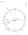
- FIG. 2 shows a friction disk 9 with a carrier 10 arranged friction lining segments 2, 2 ', 2 "etc., which according to Figure 1 are executed.
- 10 friction lining segments 2.2'2 "etc. are arranged on the carrier, each with their long ends against each other limits. All friction lining segments 2, 2 ', 2 "etc. are the same trained and each span an arc angle of 72 °.
- the adjoining longitudinal ends of two friction lining segments, for example 2 and 2 ', are by a lock element 7 and a complementary form and function Lock element 8 'connected to each other.
- the inner radii or outer radii Ri have Offset ⁇ of the center points has a ratio of 8.7. This The situation is exemplarily shown on the friction lining segment 2 '.
Landscapes
- Engineering & Computer Science (AREA)
- General Engineering & Computer Science (AREA)
- Mechanical Engineering (AREA)
- Mechanical Operated Clutches (AREA)
- Braking Arrangements (AREA)
Abstract
Description
- Ausschneiden oder Ausstanzen eines äußeren Berandungsabschnittes eines ersten Reibbelagsegments,
- Ausschneiden oder Ausstanzen eines inneren Berandungsabschnitts des ersten Reibbelagsegments der zum äußeren Berandungsabschnitt gleich ausgebildet ist, wobei der innere Berandungsabschnitt versetzt zum äußeren Berandungsabschnitt verläuft.
- Verwenden des inneren Berandungsabschnitts des ersten Reibelements als äußeren Berandungsabschnitt eines zweiten Reibelements.
- Ausschneiden oder Ausstanzen eines inneren Berandungsabschnitt des zweiten Reibbelagselements der zu den vorangegangenen Berandungsabschnitten gleich ausgebildet ist, wobei der innere Berandungsabschnitt zu den vorangegangene Berandungsabschnitten versetzt verläuft.
- Spiegelsymmetrisches Ausschneiden oder Ausstanzen eines ersten Berandungsabschnittes bezüglich einer Mittelpunktsgerade.
- Spiegelsymmetrisches Ausschneiden oder Ausstanzen eines zweiten Berandungsabschnitts, wobei dessen Mittelpunkt um einen Wert Δ zum ersten Mittelpunkt des ersten Berandungsabschnitts auf der Mittelpunktsgerade versetzt ist, und wobei der zweite Berandungsabschnitt den gleichen Bogenwinkel wie der vorangegangene erste Berandungsabschnitt überspannt.
- Spiegelsymmetrisches Ausschneiden oder Ausstanzen eines dritten Berandungsabschnitts bezüglich der Mittelpunktsgerade, wobei der dritte Mittelpunkt des dritten Berandungsabschnitts auf der Mittelpunktsgerade ebenfalls um den Wert Δ zum zweiten Mittelpunkt des zweiten Berandungsabschnitts versetzt ist, und wobei der dritte Berandungsabschnitt den gleichen Bogenwinkel wie die vorangegangenen Berandungsabschnitte überspannt.
- Figur 1
- Segmentierung eines flachen Materialabschnitts aus Fasermaterial beim erfindungsgemäßen Verfahren zur Herstellung von Reibbelagsegmenten in Draufsicht.
- Figur 2
- Ein aus erfindungsgemäßen Reibbelagsegmenten zusammengesetzter Reibbelag in Draufsicht.
- 1
- Platte
- 2
- Reibbelagsegment
- 3
- äußerer Berandungsabschnit
- 4
- Mittelpunkt (Bogenabschnit)
- 5
- Mittelpunktsgerade
- 6
- innerer Berandungsabschnitt
- 7
- Schloßelement
- 8
- Schloßgegenelement
- 9
- Reibscheibe
- 10
- Träger
- 11
- Materialverschnitt
Claims (21)
- Reibbelagsegment (2) für einen segmentierten Reibbelag einer Reibscheibe (9), wobei das Reibbelagsegment ringsegmentförmig ausgebildet ist, mit einem äußeren Berandungsabschnitt (3) und einem inneren Berandungsabschnitt (6),
dadurch gekennzeichnet, dass der äußere Berandungsabschnitt (3) und der innere Berandungsabschnitt (6) formkomplementär ausgeführt sind. - Reibbelagsegement nach Anspruch 1,
dadurch gekennzeichnet, dass der äußere Berandungsabschnitt (3) durch einen Außenradius mit einem Mittelpunkt und der innere Berandungsabschnitt (6) durch einen Innenradius mit einem Mittelpunkt beschrieben werden, und dass der Außenradius gleich dem Innenradius ist. - Reibbelagsegment nach Anspruch 1 oder 2,
dadurch gekennzeichnet, dass der äußere Berandungsabschnitt(3) und der innere Berandungsabschnitt (6) durch einen Kreisbogenabschnitt gebildet werden. - Reibbelagsegment nach Anspruch 1 bis 3,
dadurch gekennzeichnet, dass das Reibbelagsegment (2), durch zwei zueinander spiegelsymmetrische Abschnitte gebildet wird. - Reibbelagsegment nach einem der Ansprüche 1 bis 4,
dadurch gekennzeichnet, dass eine Mittelpunktgerade (5), welche sich durch die Mittelpunkte (4) der Berandungsabschnitte (3, 6) erstreckt, das Reibbelagsegment (2) in die zueinander symmetrischen Abschnitte teilt. - Reibbelagsegment nach einem der Ansprüche 1 bis 5,
dadurch gekennzeichnet, dass das Reibbelagsegment (2) einen Bogenwinkel zwischen 45° und 90°, insbesondere zwischen 70° und 80° überspannt. - Reibbelagsegment nach einem der Ansprüche 1 bis 6,
dadurch gekennzeichnet, dass der Außen- bzw. Innenradius zum Versatz (Δ) der beiden Mittelpunkte (4) auf der Mittelpunktsgerade (5) ein Verhältnis zwischen 6 und 10, insbesondere zwischen 8 und 9, aufweist. - Reibbelagsegment nach einem der Ansprüche 1 bis 7
dadurch gekennzeichnet, dass das Reibbelagsegment (2) an seinem ersten längsseitigen Ende ein Schlosselement (7) und an seinem zweiten längsseitigen Ende ein zum Schlosselement (7) form - und funktionskomplementäres Schlossgegenelement (8) aufweist. - Reibbelag für eine Reibscheibe (9) mit wenigstens zwei ringsegmentförmig ausgebildeten Reibbelagsegmenten (2) nach einem der Ansprüche 1 bis 8.
- Reibbelag nach Anspruch 9,
dadurch gekennzeichnet, dass wenigstens zwei Reibbelagsegmente (2) jeweils mit zumindest einem ihrer längsseitigen Enden aneinander grenzen. - Reibbelag nach Anspruch 9 oder 10,
dadurch gekennzeichnet, dass die aneinander grenzenden Reibbelagsegmente (2) jeweils mittels Schloss (7) des ersten Reibbelagsegments (2) und Gegenschloss (8) des zweiten Reibbelagsegments (2) miteinander verbunden sind. - Reibbelag nach Anspruch einem der Ansprüche 9 bis 11,
dadurch gekennzeichnet, dass alle der wenigsten zwei Reibbelagsegmente (2) den gleichen Bogenwinkel überspannen. - Reibbelag nach Anspruch 12,
dadurch gekennzeichnet, dass alle Reibbelagsegmente (2) gleich ausgebildet sind. - Reibbelag nach Anspruch einem der Ansprüche 7 bis 11,
dadurch gekennzeichnet, dass die zumindest zwei Reibbelagsegmente (2) zusammen einen Bogenwinkel von im Wesentlichen 360° überspannen. - Verfahren zur Herstellung von Reibbelagsegmenten (2) eines segmentierten Reibbelags, wobei die Reibbelagsegmente (2) ringsegmentförmig ausgebildet sind, mit einem äußeren (3) bzw. inneren Berandungsabschnitt (6),
dadurch gekennzeichnet, dass zumindest zwei Reibbelagsegmente (2) mit den folgenden Verfahrensschritten aus einem flachen Materialabschnitt herstellbar sind:Ausschneiden oder Ausstanzen eines äußeren Berandungsabschnitts (3) eines ersten Reibbelagsegments (2),Ausschneiden oder Ausstanzen eines inneren Berandungsabschnitts (6) des ersten Reibbelagssegments (2) der gleich zum äußeren Berandungsabschnitt (3) ist, wobei der innere Berandungsabschnitt (6) versetzt zum äußeren Berandungsabschnitt (3) verläuft,Verwenden des inneren Berandungsabschnitts (6) des ersten Reibelements (2) als äußeren Berandungsabschnitt (3') eines zweiten Reibbelagsegments (2'),Ausschneiden oder Ausstanzen eines inneren Berandungsabschnitts (3") des zweiten Reibbelagssegments (2') der gleich wie die vorangegangenen Berandungsabschnitte ist, wobei der innere Berandungsabschnitt (3") zu den vorangegangenen Berandungsabschnitten versetzt verläuft. - Verfahren zur Herstellung von Reibbelagsegmenten nach Anspruch 15,
dadurch gekennzeichnet, dass die Berandungsabschnitte (2,3,2',3',2",3") jeweils gleich zueinander versetzt sind. - Verfahren zur Herstellung von Reibbelagsegementen nach Anspruch 15 oder 16,
dadurch gekennzeichnet, dass der äußere Berandungsabschnitt (3', 3,', 3") und der innere Berandungsabschnitt (6, 6') der zumindest zwei Reibbelagsemente (2, 2') durch einen Außenradius (R1, R2, R3)mit Mittelpunkt (4, 4', 4'') bzw. durch einen Innenradius (R2, R3,) mit Mittelpunkt (4', 4") beschrieben werden, wobei alle Radien (R1, R2, R3) gleich und die Mittelpunkte (4, 4', 4") zueinander versetzt sind. - Verfahren zur Herstellung von Reibbelagsegmenten nach Anspruch 17,
dadurch gekennzeichnet, dass jeder äußere (3,3', 3") bzw. innere Berandungsabschnitt (6, 6') der zumindest zwei Reibbelagsegmente in sich spiegelsymmetrisch zu einer die zumindest drei Mittelpunkte (4, 4' 4")verbindenden Mittelpunktsgerade (5) ausgeschnitten oder ausgestanzt wird. - Verfahren zur Herstellung von Reibbelagsegmenten nach einem der Ansprüche 17 bis 18,
dadurch gekennzeichnet, dass die jeweils nebeneinander angeordneten Mittelpunkte (4, 4', 4") auf der Mittelpunktsgerade (5) gleich zueinander beabstandet sind. - Reibscheibe (9) mit einem Träger (10) und mit wenigstens einem auf wenigstens einer Stirnseite des Trägers (10) angeordnetem Reibbelag gemäß einem der Ansprüche 9 bis 14.
- Reibscheibe nach Anspruch 20,
dadurch gekennzeichnet, dass die Reibscheibe (9) in einer Schaltkupplung, Anfahrkupplung, Wandlerüberbrückungskupplung oder Bremse Verwendung findet.
Priority Applications (1)
| Application Number | Priority Date | Filing Date | Title |
|---|---|---|---|
| EP03008335A EP1467113A1 (de) | 2003-04-09 | 2003-04-09 | Reibbelagsegment und Verfahren zur Herstellung von Reibbelagsegmenten |
Applications Claiming Priority (1)
| Application Number | Priority Date | Filing Date | Title |
|---|---|---|---|
| EP03008335A EP1467113A1 (de) | 2003-04-09 | 2003-04-09 | Reibbelagsegment und Verfahren zur Herstellung von Reibbelagsegmenten |
Publications (1)
| Publication Number | Publication Date |
|---|---|
| EP1467113A1 true EP1467113A1 (de) | 2004-10-13 |
Family
ID=32864985
Family Applications (1)
| Application Number | Title | Priority Date | Filing Date |
|---|---|---|---|
| EP03008335A Withdrawn EP1467113A1 (de) | 2003-04-09 | 2003-04-09 | Reibbelagsegment und Verfahren zur Herstellung von Reibbelagsegmenten |
Country Status (1)
| Country | Link |
|---|---|
| EP (1) | EP1467113A1 (de) |
Cited By (1)
| Publication number | Priority date | Publication date | Assignee | Title |
|---|---|---|---|---|
| WO2008028656A1 (de) * | 2006-09-09 | 2008-03-13 | Daimler Ag | Synchronring mit einem faserverstärkten organischen reibbelag und herstellungsverfahren |
Citations (4)
| Publication number | Priority date | Publication date | Assignee | Title |
|---|---|---|---|---|
| US4260047A (en) * | 1979-12-03 | 1981-04-07 | General Motors Corporation | Friction disc and method of making same |
| WO1999064755A1 (en) * | 1998-06-10 | 1999-12-16 | 3M Innovative Properties Company | Friction disk assembly and method of making same |
| US6019205A (en) * | 1998-07-01 | 2000-02-01 | Raytech Automotive Components Company | Method and apparatus for lined clutch plate |
| US6409006B1 (en) * | 1999-06-22 | 2002-06-25 | Nsk-Warner K.K. | Friction plate |
-
2003
- 2003-04-09 EP EP03008335A patent/EP1467113A1/de not_active Withdrawn
Patent Citations (4)
| Publication number | Priority date | Publication date | Assignee | Title |
|---|---|---|---|---|
| US4260047A (en) * | 1979-12-03 | 1981-04-07 | General Motors Corporation | Friction disc and method of making same |
| WO1999064755A1 (en) * | 1998-06-10 | 1999-12-16 | 3M Innovative Properties Company | Friction disk assembly and method of making same |
| US6019205A (en) * | 1998-07-01 | 2000-02-01 | Raytech Automotive Components Company | Method and apparatus for lined clutch plate |
| US6409006B1 (en) * | 1999-06-22 | 2002-06-25 | Nsk-Warner K.K. | Friction plate |
Cited By (1)
| Publication number | Priority date | Publication date | Assignee | Title |
|---|---|---|---|---|
| WO2008028656A1 (de) * | 2006-09-09 | 2008-03-13 | Daimler Ag | Synchronring mit einem faserverstärkten organischen reibbelag und herstellungsverfahren |
Similar Documents
| Publication | Publication Date | Title |
|---|---|---|
| EP3374652B1 (de) | Lamelle für ein kraftschlüssiges schaltelement | |
| EP1650454B1 (de) | Trägerblech für eine Lamelle und Verfahren zu deren Herstellung | |
| EP2198176B1 (de) | Segmentiertes trägerblech für eine lamelle und lamelle mit einem solchen segmentierten trägerblech | |
| EP1371866A1 (de) | Lamelle für eine Mehrscheibenlamellenkupplung | |
| EP0521843B1 (de) | Reibring | |
| DE102007010764A1 (de) | Kupplungskörper und Synchronring für eine Synchronisierungseinrichtung | |
| WO2019204844A1 (de) | Reiblamelle | |
| DE102009048377B4 (de) | Verfahren zum Herstellen von Lamellen einer Reibkupplung | |
| DE102018001877A1 (de) | Lamellenkupplung, Lamelle für eine solche Lamellenkupplung, Verfahren zur Herstellung einer solchen Lamellenkupplung oder Lamelle | |
| DE102013111877B4 (de) | Lamellenträger mit mehreren radialen Durchbrüchen zur Kühlung eines Lamellenpakets, Lamellenkupplung und Verfahren zur Herstellung eines Lamellenträgers | |
| DE102013011677A1 (de) | Reibteil für eine reibschlüssig arbeitende Einrichtung | |
| DE3627504C2 (de) | ||
| DE69405064T2 (de) | Reibeläge tragende scheibe,insbesondere für kraftfahrzeuge | |
| DE102016102701A1 (de) | Synchronisiervorrichtung und Synchronisationsverfahren | |
| DE202019102932U1 (de) | Reiblamelle | |
| EP1457697A2 (de) | Verfahren zur Herstellung einer Reibscheibe | |
| DE102014216848B4 (de) | Rotor für einen hydraulischen Nockenwellenversteller sowie Herstellungsverfahren eines Rotors für einen Nockenwellenversteller | |
| WO2018002122A1 (de) | Welle-nabe-verbindung | |
| DE102011120343B4 (de) | Verfahren zur Herstellung eines Kupplungskörpers sowie Kupplungskörper für eine Synchronisiereinrichtung | |
| DE102010049558A1 (de) | Pendelmasse für eine Fliehkraftpendeleinrichtung | |
| EP1467113A1 (de) | Reibbelagsegment und Verfahren zur Herstellung von Reibbelagsegmenten | |
| EP3179124B1 (de) | Reiblamelle | |
| DE102017107209B4 (de) | Reiblamelle aus mehreren miteinander verbundenen Segmenten | |
| DE102015210864A1 (de) | Kupplungsanordnung | |
| DE102013101695A1 (de) | Kupplungsscheibe und Herstellungsverfahren |
Legal Events
| Date | Code | Title | Description |
|---|---|---|---|
| PUAI | Public reference made under article 153(3) epc to a published international application that has entered the european phase |
Free format text: ORIGINAL CODE: 0009012 |
|
| AK | Designated contracting states |
Kind code of ref document: A1 Designated state(s): AT BE BG CH CY CZ DE DK EE ES FI FR GB GR HU IE IT LI LU MC NL PT RO SE SI SK TR |
|
| AX | Request for extension of the european patent |
Extension state: AL LT LV MK |
|
| STAA | Information on the status of an ep patent application or granted ep patent |
Free format text: STATUS: THE APPLICATION HAS BEEN WITHDRAWN |
|
| 17P | Request for examination filed |
Effective date: 20050413 |
|
| AKX | Designation fees paid |
Designated state(s): AT BE BG CH CY CZ DE DK EE ES FI FR GB GR HU IE IT LI LU MC NL PT RO SE SI SK TR |
|
| AXX | Extension fees paid |
Extension state: MK Payment date: 20050413 Extension state: LV Payment date: 20050413 Extension state: LT Payment date: 20050413 Extension state: AL Payment date: 20050413 |
|
| 18W | Application withdrawn |
Effective date: 20050531 |