BACKGROUND OF THE INVENTION
1. Field of the Invention
-
The present invention relates to a selvage forming device for
a loom adapted to form a selvage based on the operation of a first
selvage heddle and a second selvage heddle reciprocating in opposite
directions.
2. Description of the Related Art
-
JP 10-503563 A, for example, discloses a selvage forming device
adapted to form a selvage based on the operation of a first selvage
heddle and a second selvage heddle that reciprocate in opposite
directions. In the selvage forming device as disclosed in the
above-mentioned publication, a two-dimensional crank mechanism is
driven by an electric motor, and a pair of yarn guide elements are
caused to make linear reciprocal motion through the driving of the
two-dimensional crank mechanism. The two-dimensional crank
mechanism is composed of a lever mounted to an output shaft of the
electric motor and a pair of links connected to the ends of the
lever. The pair of links are connected to the pair of yarn guide
elements through one-to-one connection.
-
The larger the opening amount of a selvage, the more smoothly
can weft picking be performed. When, in the device disclosed in
JP 10-503563 A, an attempt is to be made to increase the maximum
selvage opening amount, it is necessary to increase the rotational
radius of the lever (that is, the distance from the rotation center
axis of the lever to the position where the lever and the links
are connected together). When the rotational radius of the lever
is increased, the requisite torque for rotating the lever increases,
resulting in an increase in the load on the electric motor. This
makes it difficult to operate the electric motor at high speed,
thereby constituting an obstruction to realizing a loom of higher
speed.
SUMMARY OF THE INVENTION
-
An object of the present invention is to provide a selvage
forming device capable of enlarging the selvage opening amount
without hindering an increase in loom operation speed.
-
To attain the above object, according to the present invention,
there is provided a selvage forming device for a loom adapted to
form a selvage based on operations of a first selvage heddle and
a second selvage heddle reciprocating in opposite directions, the
device including: a first band supporting the first selvage heddle
and equipped with a plurality of power receiving holes arranged
in a row, the first band being capable of deflection; a second band
supporting the second selvage heddle and equipped with a plurality
of power receiving holes arranged in a row, the second band being
capable of deflection; and a wheel equipped with a plurality of
power transmission teeth respectively brought into mesh-engagement
with the power receiving holes of the first and second bands, in
which the first band and the second band are opposed to each other
in a deflected state, with the wheel therebetween, so as to bring
the power receiving holes of the first and second bands into
mesh-engagement with the power transmission teeth.
BRIEF DESCRIPTION OF THE DRAWINGS
-
In the accompanying drawings:
- Fig. 1 is a side sectional view of a first embodiment of the
present invention;
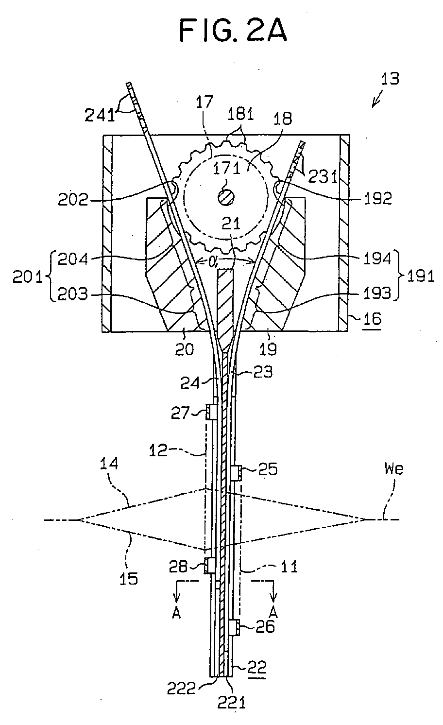
- Fig. 2a is a side sectional view as seen from the opposite
side of Fig. 1, and Fig. 2b is a sectional view taken along the
line A-A of Fig. 2a;
- Fig. 3 is a front sectional view of the first embodiment of
the present invention;
- Fig. 4 is a rear sectional view of the same;
- Fig. 5 is a front sectional view of the same;
- Fig. 6 is a side sectional view of a third embodiment of the
present invention;
- Fig. 7 is a front sectional view of the same;
- Figs. 8a and 8b are main-portion side sectional views of the
third embodiment of the present invention; and
- Figs. 9 and 10 are graphs showing positional changes in a selvage
heddle.
-
DESCRIPTION OF THE PREFERRED EMBODIMENTS
-
A selvage formation opening device according to a first
embodiment of the present invention will now be described with
reference to Figs. 1 through 4.
-
As shown in Figs. 1 and 2, a first selvage heddle 11 and a
second selvage heddle 12 are moved vertically in opposite directions
by a reciprocating drive mechanism 13. The movement paths for the
first selvage heddle 11 and the second selvage heddle 12 are vertically
extending reciprocation paths parallel to each other. Selvage yarn
14 passed through the first selvage heddle 11 and selvage yarn 15
passed through the second selvage heddle 12 form a selvage We with
picked weft (not shown) therebetween.
-
As shown in Figs. 3 and 4, an electric motor 17 is attached
to an inner wall 161 of a box 16 constituting the reciprocating
drive mechanism 13. The upper and lower portions of the box 16 are
open. An output shaft 171 of the electric motor 17 extends through
the inner wall 161 and protrudes into the box 16. The axial direction
of the output shaft 171 substantially'coincides with the weft picking
direction. The protruding end portion of the output shaft 171 is
rotatably supported by an outer wall 162 of the box 16. In the box
16, a wheel 18 is immovably mounted to the output shaft 171. In
the outer periphery of the wheel 18, there are provided a plurality
of power transmission teeth 181 (see Fig.2).
-
As shown in Figs. 1 and 2, immovably mounted to the inner surface
of the outer wall 162 of the box 16 are a first position regulating
member 19 and a second position regulating member 20. The first
position regulating member 19 and the second position regulating
member 20 are opposed to each other with the wheel 18 therebetween.
A mounting member 21 is immovably mounted to the inner surface of
the outer wall 162 of the box 16. The mounting member 21 is arranged
between the first position regulating member 19 and the second
position regulating member 20. The mounting member 21 is spaced
apart from opposing surfaces 191 and 201 of the first position
regulating member 19 and the second position regulating member 20.
-
The opposing surfaces 191 and 201 consist of guide curved
surfaces 193 and 203 convex toward the wheel 18 and guide plane
surfaces 194 and 204 smoothly continuous to the guide curved surfaces
193 and 203. The opposing surfaces 191 and 201 are convex toward
the wheel 18 and opposed to each other. The guide plane surfaces
194 and 204 are opposed to each other with the wheel 18 therebetween
so as to be diverged upwardly, and the guide curved surfaces 193
and 203 are opposed to each other with mounting member 21 therebetween
so as to be diverged upwardly. The guide plane surfaces 194 and
204 form an angle α. In this embodiment, the guide curved surfaces
193 and 203 are arcuate curved surfaces.
-
A guide rail 22 is immovably mounted to the mounting member
21 so as to extend vertically downwards. As shown in Fig. 2(b),
a pair of guide grooves 221 and 222 are formed back to back in the
guide rail 22. The guide grooves 221 and 222 are arranged adjacent
to each other so as to extend parallel to the reciprocating movement
paths of the first selvage heddle 11 and the second selvage heddle
12. The guide groove 221 is exposed on the front side of the loom
(In Figs. 1 and 2, the right-hand side corresponds to the front
side of the loom, and the left-hand side corresponds to the rear
side of the loom), and the guide groove 222 is exposed on the rear
side of the loom.
-
A part of a first band 23 which is capable of deflection is
slidably inserted into the guide groove 221, and a part of a second
band 24 which is capable of deflection is slidably inserted into
the guide groove 222. That is, the portions of the first band 23
and the second band 24 in the guide grooves 221 and 222 are adjacent
to each other so as to reciprocate parallel to the reciprocating
paths of the first selvage heddle 11 and the second selvage heddle
12. The first band 23 and the second band 24 are formed of
fiber-reinforced plastic reinforced by carbon fiber.
-
The first band 23 extends, while deflected, upwardly through
the gap between the mounting member 21 and the opposing surface
191 of the first position regulating member 19. The second band
24 extends, while deflected, upwardly through the gap between the
mounting member 21 and the opposing surface 201 of the second position
regulating member 20. Further, the first band 23 extends upwardly
between the wheel 18 and the opposing surface 191 of the first position
regulating member 19, and the second band 24 extends upwardly between
the wheel 18 and the opposing surface 201 of the second position
regulating member 20.
-
A plurality of power receiving holes 231 and 241 are provided
in rows in the first band 23 and the second band 24. The power receiving
holes 231 and 241 are in mesh with the power transmission teeth
181. That is, the first band 23 and the second band 24 are opposed
to each other in a deflected state, with the wheel 18 therebetween,
so as to keep the power receiving holes 231 and 241 of the first
band 23 and the second band 24 in mesh with the power transmission
teeth 181.
-
At the position where the power transmission holes 231 of the
first band 23 and the power transmission teeth 181 are in mesh with
each other, there is formed a clearance groove 192 in the opposing
surface 191 (the guide plane surface 194) of the first position
regulating member 19. At the position where the power transmission
holes 241 of the second band 24 and the power transmission teeth
181 are in mesh with each other, there is formed a clearance groove
202 in the opposing surface 201 (the guide plane surface 204) of
the second position regulating member 20. The power transmission
teeth 181 in mesh with the power receiving holes 231 of the first
band 23 are in the clearance groove 192, and the power transmission
teeth 181 in mesh with the power receiving holes 241 of the second
band 24 are in the clearance groove 202, whereby there is no fear
of the first position regulating member 19 and the second position
regulating member 20 interfering with the power transmission teeth
181.
-
In the following, the positions where the power receiving holes
231 and 241 are in mesh with the power transmission teeth 181 will
also be referred to as the in-mesh positions of the bands 23 and
24 and the wheel 18.
-
A pair of clasping arms 25 and 26 are immovably mounted to
the first band 23, and a pair of clasping arms 27 and 28 are immovably
mounted to the second band 24. The first selvage heddle 11 is
clasp-supported by the pair of clasping arms 25 and 26 as connecting
members, and the second selvage heddle 12 is clasp-supported by
the pair of clasping arms 27 and 28 as connecting members. That
is, the first band 23 supports the first selvage heddle 11, and
the second band 24 supports the second selvage heddle 12.
-
Next, the operation of the first embodiment will be described.
-
The output shaft 171 of the electric motor 17 makes reciprocal
rotation, causing the wheel 18 to make reciprocal rotation. The
reciprocal rotation of the wheel 18 is transmitted to the first
band 23 and the second band 24 through the meshing engagement of
the power transmission teeth 181 with the power receiving holes
231 and 241, whereby the first band 23 and the second band 24 move
vertically in the guide grooves 221 and 222 in opposite directions.
The first band 2 3 reciprocates while in slide contact with the opposing
surface 191 as a guide surface (the guide curved surface 193 and
the guide plane surface 194), and the second band 24 reciprocates
while in slide contact with the opposing surface 201 as a guide
surface (the guide curved surface 203 and the guide plane surface
204). That is, the first position regulating member 19 is in contact
with the first band 23 so as to regulate the in-mesh position of
the first band 23 and the wheel 18, and the second position regulating
member 20 is in contact with the second band 24 so as to regulate
the in-mesh position of the second band 24 and the wheel 18.
-
When the first band 23 and the second band 24 move vertically
in the guide grooves 221 and 222 in opposite directions, the first
selvage heddle 11 and the second selvage heddle 12 are moved vertically
in opposite directions. Thus, the selvage yarn 14 (see Fig. 1) passed
through the first selvage heddle 11 and the selvage yarn 15 (see
Fig. 1) passed through the second selvage heddle 12 form the selvage
We (see Fig. 1) with the picked weft (not shown) therebetween.
-
The guide rail 22 constitutes a third position regulating
member having the pair of guide grooves 221 and 222 guiding parallel
to each other. The first position regulating member 19, the second
position regulating member 20, and the guide rail 22 constitute
a guide means for guiding the first band 23 and the second band
24. This guide means brings the first band 23 and the second band
24 closer to each other as the first band 23 and the second band
24 are departed away from the in-mesh positions of the power
transmission teeth 181 and the power receiving holes 231 and 241.
Next, the guide means guides the first and second bands 23 and 24
such that a part of the first band 23 and a part of the second band
24 extend parallel to each other.
-
The first embodiment provides the following advantages:
- (1-1) When the wheel 18 is caused to make reciprocal rotation,
the first band 23 and the second band 24 reciprocate in a deflected
state in opposite directions, and the first selvage heddle 11 and
the second selvage heddle 12 reciprocate in opposite directions.
The maximum selvage yarn opening amount can be appropriately
increased by increasing the one-way rotating amount of the wheel
18 caused to make reciprocal rotation. The term "one-way rotating
amount of the wheel 18" refers to the requisite rotating amount
of the wheel 18 for causing the selvage heddles 11 and 12 to move
one going or returning stroke. The requisite torque for rotating
the wheel 18 can be reduced by reducing the radius of the wheel
18. Further, the bands 23 and 24 capable of deflection and in mesh
with the wheel 18 can be reduced in weight by reducing their thickness.
The adoption of lightweight bands 23 and 24 is effective in reducing
the requisite torque for rotating the wheel 18.
- (1-2) In the state in which the power transmission teeth 181
of the wheel 18 are in the clearance grooves 192 and 202, the power
transmission teeth 181 are in mesh with the power receiving holes
231 and 241 of the bands 23 and 24. In this state, there is no fear
of the power transmission teeth 181 being detached from the power
receiving holes 231 and 241. The first position regulating member
19 equipped with the clearance groove 192 makes the meshing engagement
between the first band 23 and the wheel 18 reliable, and the second
position regulating member 20 equipped with the clearance groove
202 makes the meshing engagement between the second band 24 and
the wheel 18 reliable.
- (1-3) The first band 23 and the second band 24 are brought
closer to each other as they are departed from the positions where
they are in mesh with the wheel 18 toward the selvage heddles 11
and 12, and then they are guided so as to extend parallel to each
other. The deflected portions of the first and second bands 23 and
24 are brought into sliding contact with the guide curve surfaces
193 and 203, and the portions of the first and second bands 23 and
24 in sliding contact with the guide plane surfaces 194 and 204
at angle α are linear. That is, the first and second bands 23 and
24 undergo deflection in the paths from the positions where they
are in mesh with the wheel 18 to the guide grooves 221 and 222.
The configuration of the deflected portions of the first and
second bands 23 and 24 from the positions where they are in mesh
with the wheel 18 to the guide grooves 221 and 222 can be adjusted
to a proper configuration through appropriate selection of the angle
α. Here, the proper configuration refers to a deflected
configuration to diminish the sliding resistance between the
position regulating members 19 and 20 and the bands 23 and 24 and
the sliding resistance between the guide rail 22 and the bands 23
and 24.
- (1-4) The configuration of the deflected portions of the first
and second bands 23 and 24 from the positions where they are in
mesh with the wheel 18 to the guide grooves 221 and 222 can be modified
to some degree by changing the radius of curvature of the guide
curved surfaces 193 and 203 that are arcuate surfaces. The guide
curved surfaces 193 and 203 contribute to adjusting to a proper
configuration of the deflected portions of the first and second
bands 23 and 24 from the positions where they are in mesh with the
wheel 18 to the guide grooves 221 and 222. Arcuate surfaces that
are easy to machine are suitable as the guide curved surfaces 193
and 203.
- (1-5) The configuration of the portions of the bands 23 and
24 upwardly diverging from the positions where they are in mesh
with the wheel 18 is linear. This linear configuration is effective
in diminishing the sliding resistance between the position
regulating members 19 and 20 and the bands 23 and 24 and the sliding
contact between the guide rail 22 and the bands 23 and 24.
- (1-6) Generally speaking, the selvage heddles 11 and 12 are
arranged in a space formed by removing the heddle frame for opening
formation in warp for forming woven cloth which is on the front
side of the loom, or are arranged at the rearmost side of the heddle
frames. In the case in which the selvage heddles 11 and 12 are arranged
in front of the heddle frame, the larger the distance between the
arrangement position of the clasping arms 25 and 26 and the arrangement
position of the clasping arms 27 and 28 in the longitudinal direction
of the loom, the farther away toward the rear side of the loom is
the position of the rearmost selvage heddle frame. Thus, the vertical
stroke amount of the rearmost selvage heddle frame increases, which
is disadvantageous in driving the selvage heddles. Further, when
the selvage heddles 11 and 12 are arranged at the rearmost of the
heddle frames, it is necessary to enlarge the opening amount of
the selvage heddles 11 and 12, which disadvantageously requires
a motor of large torque.
The fiber reinforced plastic bands 23 and 24 reinforced by
carbon fiber undergo deflection, whereby it is possible to diminish
the distance between the portions of the bands 23 and 24 parallel
to each other (i.e., the portions thereof in the guide grooves 221
and 222 of the guide rail 22). Thus, it is possible to diminish
the distance between the arrangement position of the clasping arms
25 and 26 and the arrangement position of the clasping arms 27 and
28 in the longitudinal direction of the loom. This contributes to
diminishing the stroke amount of the rearmost selvage heddle frame.
- (1-7) The first band 23 is in sliding contact with the first
position regulating member 19 formed of metal and the guide rail
22 formed of metal, and the second band 24 is in sliding contact
with the second position regulating member 20 formed of metal and
the guide rail 22 formed of metal. The sliding resistance between
the fiber reinforced plastic reinforced by carbon fiber and metal
is small. The fiber reinforced plastic reinforced by carbon fiber
is suitable as the material of the bands 23 and 24 capable of
deflection.
- (1-8) The electric motor 17 capable of being adapted to various
selvage textures independently of the loom driving motor (not shown)
is suitable as the drive source for causing the wheel 18 to make
reciprocal rotation.
-
-
Next, a second embodiment of the present invention shown in
Fig. 5 will be described. The components that are the same as those
of the first embodiment are indicated by the same reference numerals.
-
In a reciprocating drive mechanism 13A according to the second
embodiment, the electric motor 17 is attached to the box 16 through
the intermediation of an auxiliary plate 32. A driving gear 29 is
immovably mounted to the output shaft 171 of the electric motor
17. Rotatably supported by the inner wall 161 and the outer wall
162 of the box 16 is a support shaft 30, to which the wheel 18 and
a driven gear 31 are immovably mounted. The driving gear 29 is in
mesh with the driven gear 31, and the reciprocal rotation of the
output shaft 171 is transmitted to the support shaft 30 through
the meshing engagement between the driving gear 29 and the driven
gear 31, whereby the support shaft 30 and the wheel 18 integrally
make reciprocal rotation. Otherwise, this embodiment is of the same
construction as the first embodiment.
-
By appropriately selecting the gear ratio between the driving
gear 29 and the driven gear 31, it is possible to form a speed increasing
mechanism, a speed reduction mechanism, etc. This construction is
advantageous in that the speed increasing ratio, the speed reduction
ratio, etc. can be selected according to the torque characteristics
of the electric motor 17.
-
Next, a third embodiment of the present invention shown in
Fig. 6 to Fig.10 will be described. The components that are the
same as those of the first embodiment and second embodiment are
indicated by the same reference numerals.
-
As shown in Fig. 6, the first selvage heddle 11 and the second
selvage heddle 12 are caused to move in opposite directions by a
reciprocating drive mechanism 33. As shown in Fig. 7, in a box 34
constituting the reciprocating drive mechanism 33, a base frame
35 is supported so as to be rotatable through support shafts 36
and 37. The axial direction of the support shafts 36 and 37
corresponds to the weft picking direction.
-
As shown in Figs. 8(a) and 8(b), a connection shaft 38 is
rotatably supported in the base frame 35. The axis of the connection
shaft 38 is perpendicular to the axis of the support shafts 36 and
37. A T-shaped connection member 39 is fixed to the connection shaft
38, and another connection shaft 40 is fixed to the connection member
39. The axis of the connection shaft 38 and the axis of the connection
shaft 40 are perpendicular to each other.
-
An electric motor 41 is attached to the upper surface of an
upper wall 341 of the box 34. An output shaft 411 of the electric
motor 41 extends through the upper wall 341 to protrude into the
box 34, and an angle member 42 is immovably mounted to the forward
end portion of the output shaft 411. The connection shaft 40 is
rotatably connected to the angle member 42. When the output shaft
411 rotates, the connection shaft 40 revolves around the axis of
the output shaft 411. When the connection shaft 40 revolves around
the axis of the output shaft 411, the connection shaft 38 swings
around the axis of the support shafts 36 and 37. The swinging of
the connection shaft 38 is transmitted to the support shafts 36
and 37 through the base frame 35, and the support shafts 36 and
37 make reciprocal rotation. The angle member 42, the connection
shaft 40, the connection member 39, the connection shaft 38, the
base frame 35, and the support shafts 36 and 37 constitute a
three-dimensional crank mechanism 43. The support shaft 37
constitutes the reciprocal output shaft of the three-dimensional
crank mechanism 43.
-
As shown in Fig. 7, the support shaft 37 extends through a
front wall 342 of the box 34 to protrude into the exterior of the
box 34, and a driving gear 44 is immovably mounted to the protruding
end portion of the support shaft 37. A cover 45 is immovably mounted
to the front wall 342 of the box 34, and a support shaft 46 is rotatably
supported by a front wall 451 of the cover 45 and the front wall
342 of the box 34. The driven gear 31 and the wheel 18 are immovably
mounted to the support shaft 46, and the driving gear 44 is in mesh
with the driven gear 31. The number of teeth of the driving gear
44 is larger than the number of teeth of the driven gear 31. Otherwise,
this embodiment is of the same construction as the first and second
embodiments.
-
Next, the operation of the third embodiment will be described.
-
The output shaft 411 of the electric motor 41 rotates in one
direction, and this rotation in one direction of the output shaft
411 is converted into a reciprocating rotational motion by the
three-dimensional crank mechanism 43. That is, the support shaft
37 constituting the three-dimensional crank mechanism 43 makes
reciprocal rotation. When the support shaft 37 makes reciprocal
rotation, the driving gear 44 integrally makes reciprocal rotation,
and the rotation of the driving gear 44 is transmitted to the driven
gear 31, whereby the support shaft 46 makes reciprocal rotation
in a direction opposite to the rotating direction of the driving
gear 44 at a rotating speed higher than the rotating speed of the
support shaft 37. When the support shaft 46 makes reciprocal rotation,
the wheel 18 integrally makes reciprocal rotation, and the first
band 23 and the second band 24 reciprocate in opposite directions.
-
When the three-dimensional crank mechanism 43 is in the
position as shown in Fig. 8(a), the first band 23 is in the uppermost
movement position as indicated by the chain line, and the second
band 24 is in the lowermost movement position indicated by the chain
line. When the three-dimensional crank mechanism 43 is in the
position as shown in Fig. 8 (b) , the second band 24 is in the uppermost
movement position as indicated by the chain line, and the first
band 23 is in the lowermost movement position indicated by the chain
line.
-
The third embodiment provides the following advantages:
- (3-1) Curve E1 in the graph of Fig. 9 indicates the changes
in the position of the first selvage heddle 11 when the three-dimension
crank mechanism 43 is used and the rpm of the electric motor 41
is fixed. In the graph of Fig. 9, the horizontal axis indicates
the loom rotation angle, and the vertical axis indicates height
position. In Fig. 9, the line drawn as the horizontal axis coincides
with the height position of the warp line of the loom. The changes
in the position of the second selvage heddle 12 when the
three-dimensional crank mechanism 43 is used can be expressed by
curve E2 which is akin to a curve as obtained vertically reversing
curve E1 around the horizontal axis .
In the graph of Fig. 9, curve D1 indicates the changes in the
position of the first selvage heddle 11 when a conventional
two-dimensional crank mechanism is used and when the RPM of the
electric motor is fixed. The changes in the position of the second
selvage heddle 12 when the two-dimensional crank mechanism is used
can be expressed by curve D2 which is akin to a curve as obtained
vertically reversing curve D1 around the horizontal axis .In the example shown in Fig. 9, a 1/1 selvage texture is formed.
That is, the first selvage heddle 11 and the second selvage heddle
12 are vertically interchanged in their positions for each rotation
of the loom.As can be seen from comparison of curves E1 and E2 and curves
D1 and D2, the ranges on the dead point sides in the reciprocating
linear movement of the selvage heddle 11 and 12 (the so-called
stagnation ranges), in which the positional change is small, is
larger in the case in which the three-dimensional crank mechanism
43 is used than in the case in which the two-dimensional crank
mechanism is used. In the example shown, the range of loom rotation
corresponding to the height position range between the uppermost
position H1 of the selvage heddles 11 and 12 and a height position
H2 thereof close to the uppermost position H1 is a stagnation range.
Similarly, the range of loom rotation corresponding to the height
position range between the lowermost position L1 of the selvage
heddles 11 and 12 and a height position L2 thereof close to the
lowermost position L1 is a stagnation range. That is, in the example
shown, the stagnation ranges of the selvage heddles 11 and 12 when
the three-dimensional crank mechanism 43 is used can be expressed
as (Te1+Te2) and (Te3+Te4), and the stagnation ranges of the selvage
heddles 11 and 12 when the two-dimensional crank mechanism is used
can be expressed as (Td1+Td2) and (Td3+Td4).That is, a selvage (warp) opening state with an opening amount
close to the maximum opening amount can be maintained longer in
the case in which the three-dimensional crank mechanism 43 is used
than in the case in which the two-dimensional crank mechanism is
used.
- (3-2) In the device as disclosed in JP 10-503563 A, the
two-dimensional crank mechanism is driven through reciprocal
rotation of the electric motor. However, when the electric motor
is to be caused to make reciprocal rotation in a short cycle, it
is rather difficult to increase the rotating speed of the electric
motor. This difficulty leads to an obstruction to an increase in
loom operation speed. In this embodiment, in which the
three-dimensional crank mechanism 43 is driven by the electric motor
41, it is only necessary to continuously rotate the electric motor
41 solely in one direction, thus making it possible to increase
the rotating speed of the electric motor 41. The adoption of the
three-dimensional crank mechanism 43, which allows an increase in
the rotating speed of the electric motor 41, is advantageous in
achieving an increase in loom operation speed.
- (3-3) In the present invention, which uses the
three-dimensional crank mechanism 43, it is possible, when forming
a 1/1 selvage texture, to enlarge the stagnation ranges of the selvage
heddles 11 and 12 without increasing or decreasing the speed of
the electric motor 41, so that it is possible to adopt an electric
motor 41 of low torque. This helps to achieve a reduction in the
cost of the electric motor 41.
In the graph of Fig. 10, curve E3 indicates the positional
changes of the first selvage heddle 11 when the three-dimensional
crank mechanism 43 is used. In the graph of Fig. 10, the horizontal
axis indicates the loom rotating angle, and the vertical axis
indicates height position. In Fig. 10, the line drawn as the
horizontal axis coincides with the height position of the warp
line of the loom. The positional changes of the second selvage heddle
12 when the three-dimensional crank mechanism 43 is used can be
expressed by curve E4 which is akin to a curve as obtained by vertically
reversing curve E3 around the horizontal axis .In the graph of Fig. 10, curve D3 indicates the positional
changes of the first selvage heddle 11 when the conventional
two-dimensional crank mechanism is used. The positional changes
of the second selvage heddle 12 when the two-dimensional crank
mechanism is used can be expressed by curve D4 which is akin to
a curve as obtained by vertically reversing curve D3 around the
horizontal axis .In the example shown in Fig. 10, a 2/2 selvage texture is formed.
That is, the first selvage heddle 11 and the second selvage heddle
12 are vertically interchanged in their positions for each two
rotations of the loom.As indicated by curves D3 and D4, in the formation of a 2/2
selvage texture by using the two-dimensional crank mechanism,
reciprocal rotation of the electric motor requires stopping of the
electric motor and an abrupt increase and decrease in the speed
thereof. As indicated by curves E3 and E4, in the formation of a
2/2 selvage texture by using the three-dimensional crank mechanism
43, there is no need to cause the electric motor 41 to make reciprocal
rotation, so that no abrupt increase or decrease in the speed of
the electric motor 41 is required. Further, low torque suffices
when stopping and starting the electric motor 41.Further, by using the electric motor 41 as the drive source
for the three-dimensional crank mechanism 43, it is also possible
to form a complicated texture, such as a 1/3 selvage texture, without
having to abruptly increase or decrease the speed of the electric
motor 41. In the formation of a 1/3 selvage texture, the first selvage
heddle 11 and the second selvage heddle 12 are vertically interchanged
in their positions after three rotations of the loom after vertical
interchange; thereafter, they undergo vertical interchange after
one rotation of the loom.Thus, the electric motor 41, which is applicable to the
formation of various selvage textures independently of the loom
drive motor (not shown), is suitable as the drive source for the
three-dimensional crank mechanism 43.
- (3-4) The larger the reciprocation angle β (see Fig. 8(a))
of the support shaft 46, the larger the maximum opening amount of
the opening formed by the selvages 14 and 15, which is advantageous
in performing weft picking. In the three-dimensional crank
mechanism 43, it is difficult to enlarge the reciprocation angle
γ (see Fig. 8(a)) of the support shafts 36 and 37 making reciprocal
rotation. A speed increasing mechanism composed of the driving gear
44 and the driven gear 31 transmits the output from the
three-dimensional crank mechanism 43 to the wheel 18 after increasing
the output in speed. That is, the speed increasing mechanism composed
of the driving gear 44 and the driven gear 31 makes the reciprocation
angle β of the support shaft 46 larger than the reciprocation angle
γ. This speed increasing mechanism proves effective in increasing
the maximum opening amount when the three-dimensional crank
mechanism 43 is adopted.
-
-
In the present invention, the following modified embodiments
are also possible.
- (1) In the above-described embodiments, the guide curved
surfaces 193 and 203 may be curved surfaces other than arcuate
surfaces.
- (2) In the above-described embodiments, the guide curved
surfaces 193 and 203 may be omitted.
- (3) It is also possible to use rollers as the first position
regulating member 19 and the second position regulating member 20.
In this case, it is expedient to arrange the rollers such that they
press toward the wheel 18 the portions of the bands 23 and 24 at
the positions where they are in mesh with the wheel 18. However,
it is also possible to bring the rollers into contact with the portions
of the bands 23 and 24 in the ranges between the in-mesh positions
and the guide rail 22.
- (4) It is also possible to band-shaped metal plates capable
of deflection as the first band 23 and the second band 24.
- (5) It is also possible to integrate the first band 23 and
the second band 24 so as to connect them together around the upper
side of the wheel 18.
- (6) In the third embodiment, it is also possible to use a
two-dimensional crank mechanism instead of the three-dimensional
crank mechanism.
- (7) In the third embodiment, the box 34 may be formed as an
oil tank and to put lubricant oil in the box 34, thereby lubricating
the three-dimensional crank mechanism 43. In this case, since the
electric motor 41 is on top of the box 34, the box 34 can be easily
formed so as to prevent intrusion of lubricant oil into the electric
motor 41.
-
-
As described in detail above, the present invention can
advantageously provide a selvage forming device capable of enlarging
the selvage opening amount without hindering an increase in loom
operation speed.