EP1466708A2 - Sheet finisher for an image forming apparatus - Google Patents
Sheet finisher for an image forming apparatus Download PDFInfo
- Publication number
- EP1466708A2 EP1466708A2 EP04016417A EP04016417A EP1466708A2 EP 1466708 A2 EP1466708 A2 EP 1466708A2 EP 04016417 A EP04016417 A EP 04016417A EP 04016417 A EP04016417 A EP 04016417A EP 1466708 A2 EP1466708 A2 EP 1466708A2
- Authority
- EP
- European Patent Office
- Prior art keywords
- sheet
- edge
- punching
- conveyance
- finisher
- Prior art date
- Legal status (The legal status is an assumption and is not a legal conclusion. Google has not performed a legal analysis and makes no representation as to the accuracy of the status listed.)
- Granted
Links
Images


Classifications
-
- B—PERFORMING OPERATIONS; TRANSPORTING
- B65—CONVEYING; PACKING; STORING; HANDLING THIN OR FILAMENTARY MATERIAL
- B65H—HANDLING THIN OR FILAMENTARY MATERIAL, e.g. SHEETS, WEBS, CABLES
- B65H35/00—Delivering articles from cutting or line-perforating machines; Article or web delivery apparatus incorporating cutting or line-perforating devices, e.g. adhesive tape dispensers
-
- B—PERFORMING OPERATIONS; TRANSPORTING
- B26—HAND CUTTING TOOLS; CUTTING; SEVERING
- B26D—CUTTING; DETAILS COMMON TO MACHINES FOR PERFORATING, PUNCHING, CUTTING-OUT, STAMPING-OUT OR SEVERING
- B26D7/00—Details of apparatus for cutting, cutting-out, stamping-out, punching, perforating, or severing by means other than cutting
- B26D7/26—Means for mounting or adjusting the cutting member; Means for adjusting the stroke of the cutting member
- B26D7/2628—Means for adjusting the position of the cutting member
-
- B—PERFORMING OPERATIONS; TRANSPORTING
- B65—CONVEYING; PACKING; STORING; HANDLING THIN OR FILAMENTARY MATERIAL
- B65H—HANDLING THIN OR FILAMENTARY MATERIAL, e.g. SHEETS, WEBS, CABLES
- B65H37/00—Article or web delivery apparatus incorporating devices for performing specified auxiliary operations
-
- B—PERFORMING OPERATIONS; TRANSPORTING
- B65—CONVEYING; PACKING; STORING; HANDLING THIN OR FILAMENTARY MATERIAL
- B65H—HANDLING THIN OR FILAMENTARY MATERIAL, e.g. SHEETS, WEBS, CABLES
- B65H5/00—Feeding articles separated from piles; Feeding articles to machines
- B65H5/36—Article guides or smoothers, e.g. movable in operation
-
- B—PERFORMING OPERATIONS; TRANSPORTING
- B65—CONVEYING; PACKING; STORING; HANDLING THIN OR FILAMENTARY MATERIAL
- B65H—HANDLING THIN OR FILAMENTARY MATERIAL, e.g. SHEETS, WEBS, CABLES
- B65H2301/00—Handling processes for sheets or webs
- B65H2301/50—Auxiliary process performed during handling process
- B65H2301/51—Modifying a characteristic of handled material
- B65H2301/515—Cutting handled material
- B65H2301/5152—Cutting partially, e.g. perforating
-
- B—PERFORMING OPERATIONS; TRANSPORTING
- B65—CONVEYING; PACKING; STORING; HANDLING THIN OR FILAMENTARY MATERIAL
- B65H—HANDLING THIN OR FILAMENTARY MATERIAL, e.g. SHEETS, WEBS, CABLES
- B65H2511/00—Dimensions; Position; Numbers; Identification; Occurrences
- B65H2511/20—Location in space
-
- B—PERFORMING OPERATIONS; TRANSPORTING
- B65—CONVEYING; PACKING; STORING; HANDLING THIN OR FILAMENTARY MATERIAL
- B65H—HANDLING THIN OR FILAMENTARY MATERIAL, e.g. SHEETS, WEBS, CABLES
- B65H2553/00—Sensing or detecting means
- B65H2553/80—Arangement of the sensing means
- B65H2553/81—Arangement of the sensing means on a movable element
-
- B—PERFORMING OPERATIONS; TRANSPORTING
- B65—CONVEYING; PACKING; STORING; HANDLING THIN OR FILAMENTARY MATERIAL
- B65H—HANDLING THIN OR FILAMENTARY MATERIAL, e.g. SHEETS, WEBS, CABLES
- B65H2701/00—Handled material; Storage means
- B65H2701/10—Handled articles or webs
- B65H2701/13—Parts concerned of the handled material
- B65H2701/131—Edges
- B65H2701/1315—Edges side edges, i.e. regarded in context of transport
-
- Y—GENERAL TAGGING OF NEW TECHNOLOGICAL DEVELOPMENTS; GENERAL TAGGING OF CROSS-SECTIONAL TECHNOLOGIES SPANNING OVER SEVERAL SECTIONS OF THE IPC; TECHNICAL SUBJECTS COVERED BY FORMER USPC CROSS-REFERENCE ART COLLECTIONS [XRACs] AND DIGESTS
- Y10—TECHNICAL SUBJECTS COVERED BY FORMER USPC
- Y10T—TECHNICAL SUBJECTS COVERED BY FORMER US CLASSIFICATION
- Y10T83/00—Cutting
- Y10T83/141—With means to monitor and control operation [e.g., self-regulating means]
- Y10T83/145—Including means to monitor product
-
- Y—GENERAL TAGGING OF NEW TECHNOLOGICAL DEVELOPMENTS; GENERAL TAGGING OF CROSS-SECTIONAL TECHNOLOGIES SPANNING OVER SEVERAL SECTIONS OF THE IPC; TECHNICAL SUBJECTS COVERED BY FORMER USPC CROSS-REFERENCE ART COLLECTIONS [XRACs] AND DIGESTS
- Y10—TECHNICAL SUBJECTS COVERED BY FORMER USPC
- Y10T—TECHNICAL SUBJECTS COVERED BY FORMER US CLASSIFICATION
- Y10T83/00—Cutting
- Y10T83/465—Cutting motion of tool has component in direction of moving work
- Y10T83/4653—With means to initiate intermittent tool action
- Y10T83/4656—Tool moved in response to work-sensing means
- Y10T83/4664—With photo-electric work-sensing means
-
- Y—GENERAL TAGGING OF NEW TECHNOLOGICAL DEVELOPMENTS; GENERAL TAGGING OF CROSS-SECTIONAL TECHNOLOGIES SPANNING OVER SEVERAL SECTIONS OF THE IPC; TECHNICAL SUBJECTS COVERED BY FORMER USPC CROSS-REFERENCE ART COLLECTIONS [XRACs] AND DIGESTS
- Y10—TECHNICAL SUBJECTS COVERED BY FORMER USPC
- Y10T—TECHNICAL SUBJECTS COVERED BY FORMER US CLASSIFICATION
- Y10T83/00—Cutting
- Y10T83/505—Operation controlled by means responsive to product
-
- Y—GENERAL TAGGING OF NEW TECHNOLOGICAL DEVELOPMENTS; GENERAL TAGGING OF CROSS-SECTIONAL TECHNOLOGIES SPANNING OVER SEVERAL SECTIONS OF THE IPC; TECHNICAL SUBJECTS COVERED BY FORMER USPC CROSS-REFERENCE ART COLLECTIONS [XRACs] AND DIGESTS
- Y10—TECHNICAL SUBJECTS COVERED BY FORMER USPC
- Y10T—TECHNICAL SUBJECTS COVERED BY FORMER US CLASSIFICATION
- Y10T83/00—Cutting
- Y10T83/525—Operation controlled by detector means responsive to work
- Y10T83/541—Actuation of tool controlled in response to work-sensing means
Definitions
- the present invention relates to a sheet finisher mounted on or operatively connected to a printer, copier, facsimile apparatus or similar image forming apparatus for executing preselected processing with a sheet driven out of the image forming apparatus. More particularly, the present invention relates to a sheet finisher including punching means.
- a sheet finisher of the type including punching means has customarily been used with an image forming apparatus.
- the punching means punches sheets sequentially driven out of an image forming apparatus one by one and is therefore free from heavy punching loads.
- this type of punching means enhances productivity.
- a problem with such punching means is that if a sheet entered the sheet finisher is skewed, shifted in the horizontal direction or otherwise dislocated, then the hole of the sheet cannot be accurately aligned with the holes of successive sheets.
- this system determines the ideal position of a sheet to enter the sheet finisher on the basis of width information sent from an image forming apparatus. The system then compares the ideal position and the actual position of the sheet represented by the output of sheet edge sensing means and corrects a gap between the two positions.
- Japanese Patent Laid-Open Publication No. 10-279170 discloses a punching device including sheet edge sensing means responsive to the edge of a sheet, which is being conveyed by conveying means, parallel to the direction of sheet conveyance.
- First drive means moves the sheet edge sensing means in a direction perpendicular to the direction of sheet conveyance.
- Second drive means moves punching means in the direction perpendicular to the direction of sheet conveyance in accordance with information output from said sheet edge sensing means and representative of the position of the edge of the sheet. More specifically, the position where the sheet edge sensing means starts moving for sensing the edge of a sheet is set at an edge position parallel to the direction of sheet conveyance in accordance with the sheet size.
- the punching means is moved in the direction perpendicular to the direction of sheet conveyance on the basis of the edge information, thereby punching consecutive sheets at the same position without lowering image forming speed.
- the prior art punching device described above has the following problems left unsolved.
- the punching device causes punching means and sheet edge sensing means to move integrally with each other and then stops the sheet edge sensing means when it senses the edge of a sheet. Subsequently, the punching device moves the punching means by using the stop position of the sheet edge sensing means as a reference. That is, the reference position for punching is coincident with the edge of a sheet and therefore varies sheet by sheet. Consequently, the punching device needs sophisticated control and is difficult to punch a sheet at an accurate position. Moreover, in the case of a sheet of irregular size not recognized by an image forming apparatus, the punching device cannot see the width of the sheet. As a result, even when the sheet is conveyed in an ideal position, the punching means cannot be moved to the center of the sheet or punch it with accuracy because the ideal position to be compared with the actual edge position is not known.
- a sheet finisher of the present invention includes a conveying device for conveying a sheet and a punch unit for punching the sheet being conveyed by the conveying device.
- a sheet edge sensor senses the edge of the sheet, which is being conveyed by the conveying device, parallel to the direction of sheet conveyance.
- a drive source moves the sheet edge sensor in a direction perpendicular to the direction of sheet conveyance.
- Another drive source moves the punch unit in the direction perpendicular to the direction of sheet conveyance in accordance with information output from the sheet edge sensor.
- a controller controls the two drive sources by a preselected pulse ratio, thereby causing the punch unit to accurately punch the sheet.
- a sheet finisher FR embodying the present invention is shown and operatively connected to an image forming apparatus PR.
- the sheet finisher FR is generally made up of a punch unit 4, a horizontal path H1, an upper path H2, a lower path H3, a staple tray 12, an upper stack tray 9a, and a lower stack tray 9b.
- a first path selector H2t and a second path selector H3f are positioned on the horizontal path H1 for selecting the upper path H2 and lower path H3, respectively.
- the staple tray 12 is positioned on the lower path H2 while a stapler 13 is positioned at the lower end of the staple tray 12.
- the stapler 13 is capable of stapling sheets sequentially stacked and positioned on the staple tray 12 at the trailing edge of the sheet stack.
- a waiting path is included in the lower path H2 for allowing a first sheet driven out of the image forming apparatus PR to wait for a moment and be conveyed to the staple tray 12 together with a second sheet and successive sheets.
- the stapled sheet stack is lifted away from the staple tray 12 by a hook, not shown, and then driven out to the lower stack tray 9b by a belt and an outlet roller pair 8.
- the upper stack tray, or proof tray as sometimes referred to, 9a is used to stack sheets not subjected to finishing.
- the first path selector H2t on the horizontal path H1 is rotated downward (clockwise in FIG. 1) so as to unblock the upper path H2.
- the lower stack tray which bifunctions as a shift tray, 9b is configured to separate consecutive sets (copies) of sheets in a sort mode or a stack mode. More specifically, the stack tray 9 is shifted by a preselected amount in the direction perpendicular to the direction of sheet conveyance in order to shift the preceding set of sheets from the following set of sheets. To guide sheets to the stack tray 9, the first and second path selectors H2t and H3t are rotated to unblock the horizontal path H1 up to the outlet to the stack tray 9. Further, the stack tray 9 is shifted downward little by little as the number of sheets or sheet stacks positioned thereon increases. The downward shift of the stack tray 9 is effected on the basis of the output of a sheet sensor, not shown, responsive to the upper surface of the top sheet positioned on the stack tray 9.
- FIG. 3 shows the most upstream side of the horizontal path H1 in detail.
- a skew correction roller pair or inlet roller pair 1 there are arranged a skew correction roller pair or inlet roller pair 1, an inlet sensor 2, a horizontal registration sensing unit 3, the punch unit 4, and a hopper 5.
- the horizontal registration sensing unit 3 is positioned upstream of the punch unit 4 in the direction of sheet conveyance.
- a lower punch guide 20 and an upper punch guide 21 are positioned upstream of the sensing unit 3 in the direction of sheet conveyance.
- the sensing unit 3 includes a sheet edge sensor 14 responsive to the edge of a sheet parallel to the direction of sheet conveyance.
- the punch unit 4 includes a punching edge 15 supported by a holder 37 at its upper end.
- a cam 38 is inserted in the holder 37 and held in contact with a shaft 16 with eccentricity,
- a motor 18 drives the punching edge 15 via a one-rotation clutch 17.
- a second stepping motor 23 causes the punching edge 15 to move in the direction perpendicular to the direction of sheet conveyance.
- a timing belt 24, a gear/pulley 36, a rack 19 and a lower stationary guide 35 are additionally included in the punch unit 4.
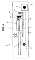
- FIG. 4 shows the horizontal registration sensing unit 3 in a side elevation while FIG. 5 shows the punch unit 4 in a side elevation.
- the sheet edge sensor 14 responsive to the edge of a sheet entering the horizontal registration sensing unit 2 is movable in the direction perpendicular to the direction of sheet conveyance (leftward in FIG. 4).
- the sheet edge sensor 14 is mounted on a sheet guide 25, which is mounted on a holder 28 and movable on a shaft 27 in the direction perpendicular to the direction of sheet conveyance (right-and-left direction in FIG. 4).
- a timing belt 32 is engaged with the holder 28 and passed over a drive pulley 30a mounted on the output shaft of a first stepping motor 30 and a driven pulley 34.
- the first stepping motor 30 causes the timing belt 32 to move between the two pulleys 30a and 34. Consequently, the timing belt 32 move the holder 28, sheet guide 25 and sheet edge sensor 14 back and forth in the direction perpendicular to the direction of sheet conveyance.
- Part of the holder 28 is configured to define the home position (stand-by position) HP of the sheet edge sensor 14 to which a home position sensor 29 is responsive.
- the sheet edge sensor 14 moves, when driven by the stepping motor 30 via the timing belt 32, from the home position HP leftward along the shaft 27 for sensing the edge of a sheet parallel to the direction of sheet conveyance.
- FIG. 6 demonstrates how the horizontal registration sensing unit 3 senses the shift or dislocation of a sheet S in the horizontal direction.
- the sheet edge sensor 14 moves a distance a for a single pulse of the first stepping motor 30.
- the sheet edge sensor 14 moves a distance w of 10a from the home position HP until it senses the edge S1 of the sheet S parallel to the direction of sheet conveyance.
- the punch unit 4 punches the sheet S in the following manner.
- the motor 18 causes the shaft 16 to make one rotation via the one-rotation clutch 17.
- the one-way clutch 17 is coupled on the elapse of a preselected period of time since the trailing edge of the sheet S has moved away from the inlet sensor 2.
- the shaft 16 in rotation causes the cam 38 contacting it to rotate and move the holder 37 in the up-and-down direction, as indicated by an arrow in FIG. 5.
- the punching edge 15 punches the sheet S when lowered in accordance with the movement of the holder 37.
- a type of punching system may be replaced with a rotary punching system, if desired.
- the rotary punching system uses a punching edge and a die mounted on a rotary body and causes them to punch a sheet in accordance with the rotation of the rotary body.
- the second stepping motor 23 causes the gear/pulley 36 to rotate via the drive pulley 23a and timing belt 24.
- the gear/pulley 36 causes the rack 19 meshing therewith to move in the right-and-left direction, as viewed in FIG. 5.
- the rack 19 is mounted on the lower punch guide 21 while the punching edge 15, upper punch guide 20, shaft 16, cam 38, holder 37, clutch 17 and motor 18 all are connected to the lower guide plates 21. Consequently, the rack 19 in movement causes all of such structural members to move in the direction perpendicular to the direction of sheet conveyance together.
- the shift 1a of the sheet S represented by the Eq. (1) indicates that a shift corresponding to a single pulse has occurred in the horizontal direction. It is therefore necessary to input pulses corresponding to the distance of 1a to the second stepping motor 23.
- the number of pulses to be input to the second stepping motor is two times as great as the number of pulses corresponding to the shift derived from the sheet edge sensor 14 because of the relation indicated by the Eq. (2).
- information output from the sheet edge sensor 14 is recognized in terms of pulses and input to a CPU (Central Processing Unit) included in a control circuit, although not shown specifically.
- the CPU compares the number of pulses with sheet size (width) information to thereby calculate the shift of the sheet S in the horizontal direction.
- a number of pulses corresponding to the calculated shift are input to the second stepping motor 23, thereby moving the structural members via the rack 19. It is noteworthy that the number of pulses to be input to the second stepping motor 23 is determined by the Eq. (2) and therefore involves a minimum of error, thereby insuring an accurate punching position. Moreover, because the number of pulses to be input to the second stepping motor 23 is determined by the Eq. (2) without regard to the shift, easy software control is achievable.
- the sheet edge sensor 14 is moved from the home position HP leftward in FIG. 4 in order to sense the edge S1 of the sheet S and then returned to the home position HP before the rack 19 moves the associated members for punching leftward in FIG. 5. More specifically, the sheet edge sensor 14 sensed the edge S1 of the sheet S must be returned to the home position in order to sense the edge of the next sheet S. Therefore, the more rapid the return of the sheet edge sensor 14 to the home position HP, the higher the productivity of the image forming apparatus PR.
- the sheet edge sensor 14 must not interfere with the conveyance of the sheet S when located at the home position HP. To cope with various sheet sizes including lengths and widths, it is necessary for the sheet edge sensor 14 to start moving from the home position HP leftward in FIG. 4 along a guide member. Usually, a guide member fixed in place in the movable range of the sheet edge sensor 14 obstructs the movement of the sensor 14.
- the upper guide 26 and lower guide 31 are constructed integrally with the sheet edge sensor 14. This allows the sheet edge sensor 14 to move in the above direction while bifunctioning as a guide for stabilizing the conveyance of the sheet S. Further, the upper guide 26 and lower guide 31 move together with the sheet edge sensor 14 while respectively overlapping an upper stationary guide 33 and the lower stationary guide 35, playing the role of a sheet guide.
- the illustrative embodiment enhances accurate register of holes formed in consecutive sheets.
- the sheet S punched at the accurate position is driven out to the lower stack tray 9b by the outlet roller pair 8 via a roller pair 7 on the horizontal path H1.
- the stack tray 9b may be moved back and forth in the direction perpendicular to the direction of sheet conveyance in order to classify the consecutive sheets or sheet stacks.
- the first and second path selectors H2t and H3t are so positioned as to steer the sheet S to the lower path H3.
- a roller pair 10 conveys the sheet S entered the lower path H3 toward the staple tray 12.
- Such sheets S are sequentially stacked and positioned on the staple tray 12 and then stapled together by the stapler 13. Further, consecutive sheets S will be simply driven out to the upper stack tray 9a without any finishing if the first path selector H2t is so positioned. Wastes derived from punched sheets S are collected in the hopper 5 shown in FIGS. 3 and 5.
- FIG. 2 shows a modification of the illustrative embodiment in which the punching device is positioned upstream of the sheet finisher FR in the direction of sheet conveyance.
- the punch unit 4 may be constructed independently of the sheet finisher FR and positioned upstream of the sheet finisher FR in the direction of sheet conveyance, i.e., between the image forming apparatus PR and the finisher FR.
- the horizontal registration sensing unit 3 and punch unit 4 shown in FIGS. 3 through 5 are constructed into a unit intervening between the image forming apparatus PR and the sheet finisher FR.
- the modification is identical with the illustrative embodiment except that the inlet roller pair 1 is positioned at the most upstream side of the horizontal path H1 in the direction of sheet conveyance.
- a second embodiment of the present invention differs from the first embodiment in that it senses opposite edges of the sheet S parallel to the direction of sheet conveyance and then sets a punching position on the basis of the position of one of the opposite edges sensed.
- the sheet finisher FR itself and the system of the second embodiment are identical with those of the first embodiment and will not be described specifically in order to avoid redundancy.
- structural elements of the second embodiment identical with those of the first embodiment are designated by identical reference numerals and will not be described specifically.
- the sheet edge sensor 14 responsive to the edge of the sheet S entering the horizontal registration sensing unit 3 is movable in the direction perpendicular to the direction of sheet conveyance (leftward in FIG. 8), as in the first embodiment.
- the sheet edge sensor 14 is mounted on the holder 28, which is movable on the shaft 27 in the direction perpendicular to the direction of sheet conveyance (right-and-left direction in FIG. 8).
- the timing belt 32 is engaged with the holder 28 and passed over the drive pulley 30a mounted on the output shaft of the first stepping motor 30 and the driven pulley 34.
- the first stepping motor 30 causes the timing belt 32 and therefore the holder 28 and sheet edge sensor 14 to move.
- Part of the holder 28 is configured to define a first home position (stand-by position) HP1 of the sheet edge sensor 14 to which a HP sensor 29 senses.
- the first stepping motor 30 causes the sheet edge sensor 14 to move along the shaft 27 from the stand-by position HP1 leftward, as viewed in FIG. 8, via the intermediate members, so that the sensor 14 senses opposite edges S1 and S2 of the sheet S parallel to the direction of sheet conveyance.
- the horizontal registration sensing unit 3 intervenes between the upper and lower punch guides 33 and 35 and the upper and lower inlet guides 21 and 20.
- the sheet edge sensor 14 moves over the entire range covered by the upper and lower punch guides 33 and 35, i.e., over the entire width of the sheet S between the edges S1 and S2 of the sheet S (see FIG. 10).
- the sheet edge sensor 14 can therefore read even the width, i.e., opposite edges of a sheet of irregular size not recognized by the image forming apparatus PR.
- FIG. 10 for describing a specific procedure that the illustrative embodiment executes when the sheet S entered the horizontal registration sensing unit 3 via the screw correction roller pair 1 is of an irregular size not recognized by the image forming apparatus PR.
- the sheet edge sensor 14 moves a distance a for a single pulse of the first stepping motor 30. If the sheet S is of irregular size not recognized by the image forming apparatus PR, then the positions of the opposite edges S1 and S2 of the sheet S (width) are not known. In light of this, the sheet edge sensor 14 moves from the stand-by position HP1 to the left in FIG. 10.
- the sheet edge sensor 14 moves a distance of 10a until it senses one edge S1 of the sheet S and then moves a distance of 100a until it senses the other edge S2 of the sheet S. Then, the distances the sheet edge sensor 14 moved to the opposite edges S1 and S2 can be determined. It follows that the distance between the stand-by position HP1 and the center SC of the sheet S being conveyed is determined to be 60a. By using this distance, it is possible to calculate the shift or difference of the center SC of the sheet S from the reference center of a sheet to be accurately conveyed without any shift in the horizontal direction.
- the punch unit 4 is moved by a distance based on the above shift of horizontal registration, so that the punching edge 15 can accurately punch the sheet S at the expected position. That is, the punch unit 4 can be located at a position where the shift of the horizontal registration is corrected.
- the sheet edge sensor 14 may be moved from the second home position SP2 to which the second home position sensor 25 is responsive rightward, as viewed in FIG. 8, to thereby sense the opposite edges of the following sheet S. This allows the sheet edge sensor 14 to efficiently sense the edges of the consecutive sheets S with respect to time. Even if the second home position sensor 25 is not used, the sheet edge sensor 14 can be alternately moved from the opposite home positions HP1 and HP2 if the number of pulses input to the first stepping motor 30 is stored.
- FIG. 9 shows another specific configuration of the horizontal registration sensing unit 3.
- the single sheet edge sensor 14 shown in FIG. 8 is replaced with a first and a second sheet edge sensor 14a and 14b respectively responsive to the edges S1 and S2 of the sheet S.
- the two sheet edge sensors 14a and 14b are respectively mounted on a first and a second holder 28a and 28b, which are movable on the shaft 27 in the direction perpendicular to the direction of sheet conveyance.
- the holders 28a and 28b are respectively fixed to the upper run and the lower run of the timing belt 32 and therefore move toward each other (inward arrows in FIG. 9) or away from each other (outward arrows in FIG. 9).
- the timing belt 32 is passed over the drive timing pulley 30a of the first stepping motor 30 and the driven timing pulley 34 and caused to move by the stepping motor 30.
- the home positions (stand-by positions) HP1 and HP2 of the sheet edge sensors 14a and 14b, respectively, are defined by part of the configuration of the first holder 28a to which the home position sensor 29 is responsive.
- the sheet edge sensors 14a and 14b are moved from their home positions HP1 and HP2, respectively, by the first stepping motor 30, as indicated by inward arrows.
- the sheet edge sensors 14a and 14b can therefore read even the shift of the sheet S of irregular size not recognized by the image forming apparatus RP
- FIG. 11 for describing a specific procedure that the configuration of FIG. 10 executes when the sheet S entered the horizontal registration sensing unit 3 via the screw correction roller pair 1 is of irregular size not recognized by the image forming apparatus PR.
- the sheet edge sensors 14 each move a distance a for a single pulse of the first stepping motor 30. Because the sheet S is of irregular size not recognized by the image forming apparatus PR, the positions of the opposite edges S1 and S2 of the sheet S (width) are not known.
- the two sheet edge sensors 14a and 14b both are moved toward and away from each other by a single stepping motor 30. Therefore, even after the sheet edge sensor 14b has sensed the edge S2 of the sheet S on moving the distance of 9a from the home position HP2, the stepping motor 30 continuously rotates. Subsequently, the sheet edge sensor 14b stops moving when the sheet edge sensor 14a senses the edge S1 of the sheet S. This not only reduces cost with a single drive source, but also obviates time losses because the two sensors 14a and 14b start moving at the same time.
- Information output from the sheet edge sensors 14a and 14b are input to the CPU of the control circuit.
- the CPU controls the number of pulses to be input to the second stepping motor 23 in the same manner as in the previous embodiment, thereby accurately locating the punch unit 4.
- the illustrative embodiment is identical with the previous embodiment.
- the illustrative embodiment After determining the shift of the sheet S from the reference center free from shift with the two sheet edge sensors 14a and 14b, the illustrative embodiment adds the shift to the distance of movement of the punch unit 4 for thereby locating two punching edges 15 symmetrically with respect to the center SC of the sheet S being conveyed. This will be described more specifically with reference to FIG. 12.
- each punching edge 15 is moved from its stand-by position by a distance of b . Then, if the punching edges 15 each are moved by the distance of b from the respective stand-by position, they can punch the sheet S at symmetrical positions with respect to the center SC of the sheet S. Therefore, as shown in FIG. 12, (b), when the sheet S is shifted by 1a in the horizontal direction, the punching edges 15 each are moved from the stand-by position by a distance of (b + 1a) to thereby punch the sheet S at symmetrical positions with respect to the center SC of the sheet S.
- the illustrative embodiment can punch even a sheet of irregular size at an accurate position.
- the illustrative embodiment can execute various modes including the shift mode and staple mode like the previous embodiment.
- staple mode the waste of the sheet S produced by punching is collected in the hopper 5 shown in FIGS. 3 and 5.
- the present invention provides a sheet finisher capable of insuring accurate punching with simple control by driving first and second drive means with a preselected pulse ratio. Further, sheet edge sensing means senses opposite edges of a sheet parallel to the direction of sheet conveyance, so that even a sheet of irregular size not recognized by an image forming apparatus can be accurately punched at its center.
Abstract
Description
- The present invention relates to a sheet finisher mounted on or operatively connected to a printer, copier, facsimile apparatus or similar image forming apparatus for executing preselected processing with a sheet driven out of the image forming apparatus. More particularly, the present invention relates to a sheet finisher including punching means.
- A sheet finisher of the type including punching means has customarily been used with an image forming apparatus. The punching means punches sheets sequentially driven out of an image forming apparatus one by one and is therefore free from heavy punching loads. In addition, this type of punching means enhances productivity. However, a problem with such punching means is that if a sheet entered the sheet finisher is skewed, shifted in the horizontal direction or otherwise dislocated, then the hole of the sheet cannot be accurately aligned with the holes of successive sheets.
- In order to solve the above problem, there has been proposed a system that corrects the skew of a sheet and, in addition, reads one edge of the sheet parallel to the direction of sheet conveyance and then corrects the shift of the sheet in accordance with the resulting information. More specifically, this system determines the ideal position of a sheet to enter the sheet finisher on the basis of width information sent from an image forming apparatus. The system then compares the ideal position and the actual position of the sheet represented by the output of sheet edge sensing means and corrects a gap between the two positions.
- For example, Japanese Patent Laid-Open Publication No. 10-279170 discloses a punching device including sheet edge sensing means responsive to the edge of a sheet, which is being conveyed by conveying means, parallel to the direction of sheet conveyance. First drive means moves the sheet edge sensing means in a direction perpendicular to the direction of sheet conveyance. Second drive means moves punching means in the direction perpendicular to the direction of sheet conveyance in accordance with information output from said sheet edge sensing means and representative of the position of the edge of the sheet. More specifically, the position where the sheet edge sensing means starts moving for sensing the edge of a sheet is set at an edge position parallel to the direction of sheet conveyance in accordance with the sheet size. The punching means is moved in the direction perpendicular to the direction of sheet conveyance on the basis of the edge information, thereby punching consecutive sheets at the same position without lowering image forming speed.
- The prior art punching device described above has the following problems left unsolved. The punching device causes punching means and sheet edge sensing means to move integrally with each other and then stops the sheet edge sensing means when it senses the edge of a sheet. Subsequently, the punching device moves the punching means by using the stop position of the sheet edge sensing means as a reference. That is, the reference position for punching is coincident with the edge of a sheet and therefore varies sheet by sheet. Consequently, the punching device needs sophisticated control and is difficult to punch a sheet at an accurate position. Moreover, in the case of a sheet of irregular size not recognized by an image forming apparatus, the punching device cannot see the width of the sheet. As a result, even when the sheet is conveyed in an ideal position, the punching means cannot be moved to the center of the sheet or punch it with accuracy because the ideal position to be compared with the actual edge position is not known.
- Technologies relating to the present invention are also disclosed in, e.g., Japanese Patent Laid-Open Publication No. 9-249348.
- It is an object of the present invention to provide a sheet finisher with punching means capable of accurately punching a sheet with simple control.
- It is another object of the present invention to provide a sheet finisher with punching means capable of accurately punching a sheet at the center even when the sheet is of irregular size not recognized by an image forming apparatus.
- A sheet finisher of the present invention includes a conveying device for conveying a sheet and a punch unit for punching the sheet being conveyed by the conveying device. A sheet edge sensor senses the edge of the sheet, which is being conveyed by the conveying device, parallel to the direction of sheet conveyance. A drive source moves the sheet edge sensor in a direction perpendicular to the direction of sheet conveyance. Another drive source moves the punch unit in the direction perpendicular to the direction of sheet conveyance in accordance with information output from the sheet edge sensor. A controller controls the two drive sources by a preselected pulse ratio, thereby causing the punch unit to accurately punch the sheet.
- The above and other objects, features and advantages of the present invention will become more apparent from the following detailed description taken with the accompanying drawings in which:
- FIG. 1 is a view showing the general construction of a first and a second embodiment of the sheet finisher in accordance with the present invention;
- FIG. 2 is a view showing a modification of either one of the first and second embodiments;
- FIG. 3 is a view showing a horizontal registration sensing unit and a punch unit included in the first embodiment;
- FIG. 4 demonstrates how the horizontal registration sensing unit of the first embodiment senses the edge of a sheet;
- FIG. 5 demonstrates how the punching unit of the first and second embodiments is adjusted in punching position and punches a sheet;
- FIG. 6 is a view for describing the operation of the horizontal registration sensing unit of the first embodiment;
- FIG. 7 is a view showing a horizontal registration sensing unit and the punching unit of the second embodiment;
- FIG. 8 demonstrates the operation of the horizontal registration sensing unit of the second embodiment that uses a single sheet edge sensor;
- FIG. 9 is a view similar to FIG. 8, demonstrating the operation of the horizontal registration sensing unit of the second embodiment that uses two sheet edge sensors;
- FIG. 10 is a view for describing the operation of the horizontal registration sensing unit shown in FIG. 8;
- FIG. 11 is a view for describing the operation of the horizontal registration sensing unit shown in FIG. 9; and
- FIG. 12 is a view showing how the punching unit of the second embodiment is adjusted in punching position.
-
- Preferred embodiments of the sheet finisher in accordance with the present invention will be described hereinafter.
- Referring to FIG. 1 of the drawings, a sheet finisher FR embodying the present invention is shown and operatively connected to an image forming apparatus PR. As shown, the sheet finisher FR is generally made up of a
punch unit 4, a horizontal path H1, an upper path H2, a lower path H3, astaple tray 12, anupper stack tray 9a, and alower stack tray 9b. - A first path selector H2t and a second path selector H3f are positioned on the horizontal path H1 for selecting the upper path H2 and lower path H3, respectively. The
staple tray 12 is positioned on the lower path H2 while astapler 13 is positioned at the lower end of thestaple tray 12. Thestapler 13 is capable of stapling sheets sequentially stacked and positioned on thestaple tray 12 at the trailing edge of the sheet stack. In addition, a waiting path, not shown, is included in the lower path H2 for allowing a first sheet driven out of the image forming apparatus PR to wait for a moment and be conveyed to thestaple tray 12 together with a second sheet and successive sheets. - The stapled sheet stack is lifted away from the
staple tray 12 by a hook, not shown, and then driven out to thelower stack tray 9b by a belt and anoutlet roller pair 8. - The upper stack tray, or proof tray as sometimes referred to, 9a is used to stack sheets not subjected to finishing. To guide sheets to the
upper stack tray 9a, the first path selector H2t on the horizontal path H1 is rotated downward (clockwise in FIG. 1) so as to unblock the upper path H2. - The lower stack tray, which bifunctions as a shift tray, 9b is configured to separate consecutive sets (copies) of sheets in a sort mode or a stack mode. More specifically, the stack tray 9 is shifted by a preselected amount in the direction perpendicular to the direction of sheet conveyance in order to shift the preceding set of sheets from the following set of sheets. To guide sheets to the stack tray 9, the first and second path selectors H2t and H3t are rotated to unblock the horizontal path H1 up to the outlet to the stack tray 9. Further, the stack tray 9 is shifted downward little by little as the number of sheets or sheet stacks positioned thereon increases. The downward shift of the stack tray 9 is effected on the basis of the output of a sheet sensor, not shown, responsive to the upper surface of the top sheet positioned on the stack tray 9.
- FIG. 3 shows the most upstream side of the horizontal path H1 in detail. As shown, there are arranged a skew correction roller pair or
inlet roller pair 1, aninlet sensor 2, a horizontalregistration sensing unit 3, thepunch unit 4, and ahopper 5. The horizontalregistration sensing unit 3 is positioned upstream of thepunch unit 4 in the direction of sheet conveyance. Alower punch guide 20 and anupper punch guide 21 are positioned upstream of thesensing unit 3 in the direction of sheet conveyance. Thesensing unit 3 includes asheet edge sensor 14 responsive to the edge of a sheet parallel to the direction of sheet conveyance. - The
punch unit 4 includes a punchingedge 15 supported by aholder 37 at its upper end. Acam 38 is inserted in theholder 37 and held in contact with ashaft 16 with eccentricity, Amotor 18 drives the punchingedge 15 via a one-rotation clutch 17. Asecond stepping motor 23 causes the punchingedge 15 to move in the direction perpendicular to the direction of sheet conveyance. Atiming belt 24, a gear/pulley 36, arack 19 and a lowerstationary guide 35 are additionally included in thepunch unit 4. FIG. 4 shows the horizontalregistration sensing unit 3 in a side elevation while FIG. 5 shows thepunch unit 4 in a side elevation. - The
sheet edge sensor 14 responsive to the edge of a sheet entering the horizontalregistration sensing unit 2 is movable in the direction perpendicular to the direction of sheet conveyance (leftward in FIG. 4). As shown in FIG. 4, thesheet edge sensor 14 is mounted on asheet guide 25, which is mounted on aholder 28 and movable on ashaft 27 in the direction perpendicular to the direction of sheet conveyance (right-and-left direction in FIG. 4). Atiming belt 32 is engaged with theholder 28 and passed over adrive pulley 30a mounted on the output shaft of afirst stepping motor 30 and a drivenpulley 34. Thefirst stepping motor 30 causes thetiming belt 32 to move between the twopulleys timing belt 32 move theholder 28,sheet guide 25 andsheet edge sensor 14 back and forth in the direction perpendicular to the direction of sheet conveyance. - Part of the
holder 28 is configured to define the home position (stand-by position) HP of thesheet edge sensor 14 to which ahome position sensor 29 is responsive. Thesheet edge sensor 14 moves, when driven by the steppingmotor 30 via thetiming belt 32, from the home position HP leftward along theshaft 27 for sensing the edge of a sheet parallel to the direction of sheet conveyance. - FIG. 6 demonstrates how the horizontal
registration sensing unit 3 senses the shift or dislocation of a sheet S in the horizontal direction. Assume that thesheet edge sensor 14 moves a distance a for a single pulse of thefirst stepping motor 30. Also, assume that when the sheet S enters thesensing unit 3 without any shift in the horizontal direction, thesheet edge sensor 14 moves a distance w of 10a from the home position HP until it senses the edge S1 of the sheet S parallel to the direction of sheet conveyance. Then, if thesensor 14 moves a distance of 11a until it actually senses the above edge S1 of the sheet S, the sheet S is shifted in the horizontal direction by a distance expressed as: - In such a case, it is necessary to move the
punch unit 4 in the direction perpendicular to the direction of sheet conveyance (leftward as indicated by an arrow in FIG. 5) in order to correct the above shift 1a. - The
punch unit 4 punches the sheet S in the following manner. Themotor 18 causes theshaft 16 to make one rotation via the one-rotation clutch 17. It is to be noted that the one-way clutch 17 is coupled on the elapse of a preselected period of time since the trailing edge of the sheet S has moved away from theinlet sensor 2. Theshaft 16 in rotation causes thecam 38 contacting it to rotate and move theholder 37 in the up-and-down direction, as indicated by an arrow in FIG. 5. As a result, the punchingedge 15 punches the sheet S when lowered in accordance with the movement of theholder 37. - While the illustrative embodiment uses a press-and-punch type of punching system that punches a sheet by stopping the sheet for a moment, such a type of punching system may be replaced with a rotary punching system, if desired. The rotary punching system uses a punching edge and a die mounted on a rotary body and causes them to punch a sheet in accordance with the rotation of the rotary body.
- In the illustrative embodiment, it is necessary to move the
punch unit 4 in the direction perpendicular to the direction of conveyance in order to correct the shift of the sheet, as stated earlier. For this purpose, thesecond stepping motor 23 causes the gear/pulley 36 to rotate via thedrive pulley 23a andtiming belt 24. The gear/pulley 36, in turn, causes therack 19 meshing therewith to move in the right-and-left direction, as viewed in FIG. 5. Therack 19 is mounted on thelower punch guide 21 while the punchingedge 15,upper punch guide 20,shaft 16,cam 38,holder 37, clutch 17 andmotor 18 all are connected to thelower guide plates 21. Consequently, therack 19 in movement causes all of such structural members to move in the direction perpendicular to the direction of sheet conveyance together. - Assume that the above structural members moved by the
rack 19 move a distance b for a single pulse of the steppingmotor 23, and that the distance b is approximate to an integral multiple of the previously stated distance a, e.g., two times as great as the distance a. Then, the distances a and b have the following relation: - The shift 1a of the sheet S represented by the Eq. (1) indicates that a shift corresponding to a single pulse has occurred in the horizontal direction. It is therefore necessary to input pulses corresponding to the distance of 1a to the
second stepping motor 23. The number of pulses to be input to the second stepping motor is two times as great as the number of pulses corresponding to the shift derived from thesheet edge sensor 14 because of the relation indicated by the Eq. (2). - More specifically, information output from the
sheet edge sensor 14 is recognized in terms of pulses and input to a CPU (Central Processing Unit) included in a control circuit, although not shown specifically. The CPU compares the number of pulses with sheet size (width) information to thereby calculate the shift of the sheet S in the horizontal direction. A number of pulses corresponding to the calculated shift are input to thesecond stepping motor 23, thereby moving the structural members via therack 19. It is noteworthy that the number of pulses to be input to thesecond stepping motor 23 is determined by the Eq. (2) and therefore involves a minimum of error, thereby insuring an accurate punching position. Moreover, because the number of pulses to be input to thesecond stepping motor 23 is determined by the Eq. (2) without regard to the shift, easy software control is achievable. - In the illustrative embodiment, the
sheet edge sensor 14 is moved from the home position HP leftward in FIG. 4 in order to sense the edge S1 of the sheet S and then returned to the home position HP before therack 19 moves the associated members for punching leftward in FIG. 5. More specifically, thesheet edge sensor 14 sensed the edge S1 of the sheet S must be returned to the home position in order to sense the edge of the next sheet S. Therefore, the more rapid the return of thesheet edge sensor 14 to the home position HP, the higher the productivity of the image forming apparatus PR. - The
sheet edge sensor 14 must not interfere with the conveyance of the sheet S when located at the home position HP. To cope with various sheet sizes including lengths and widths, it is necessary for thesheet edge sensor 14 to start moving from the home position HP leftward in FIG. 4 along a guide member. Usually, a guide member fixed in place in the movable range of thesheet edge sensor 14 obstructs the movement of thesensor 14. In light of this, in the illustrative embodiment, theupper guide 26 andlower guide 31 are constructed integrally with thesheet edge sensor 14. This allows thesheet edge sensor 14 to move in the above direction while bifunctioning as a guide for stabilizing the conveyance of the sheet S. Further, theupper guide 26 andlower guide 31 move together with thesheet edge sensor 14 while respectively overlapping an upperstationary guide 33 and the lowerstationary guide 35, playing the role of a sheet guide. - By sensing the edge of the sheet S and then moving the
punch unit 4 in accordance with the position of the sheet edge, as stated above, the illustrative embodiment enhances accurate register of holes formed in consecutive sheets. The sheet S punched at the accurate position is driven out to thelower stack tray 9b by theoutlet roller pair 8 via aroller pair 7 on the horizontal path H1. At this instant, in a shift mode, thestack tray 9b may be moved back and forth in the direction perpendicular to the direction of sheet conveyance in order to classify the consecutive sheets or sheet stacks. - In a staple mode, the first and second path selectors H2t and H3t are so positioned as to steer the sheet S to the lower path H3. A
roller pair 10 conveys the sheet S entered the lower path H3 toward thestaple tray 12. Such sheets S are sequentially stacked and positioned on thestaple tray 12 and then stapled together by thestapler 13. Further, consecutive sheets S will be simply driven out to theupper stack tray 9a without any finishing if the first path selector H2t is so positioned. Wastes derived from punched sheets S are collected in thehopper 5 shown in FIGS. 3 and 5. - FIG. 2 shows a modification of the illustrative embodiment in which the punching device is positioned upstream of the sheet finisher FR in the direction of sheet conveyance. As shown, the
punch unit 4 may be constructed independently of the sheet finisher FR and positioned upstream of the sheet finisher FR in the direction of sheet conveyance, i.e., between the image forming apparatus PR and the finisher FR. In this modification, the horizontalregistration sensing unit 3 and punchunit 4 shown in FIGS. 3 through 5 are constructed into a unit intervening between the image forming apparatus PR and the sheet finisher FR. As for the rest of the construction, the modification is identical with the illustrative embodiment except that theinlet roller pair 1 is positioned at the most upstream side of the horizontal path H1 in the direction of sheet conveyance. - A second embodiment of the present invention will be described with reference to FIGS. 7 through 12. Briefly, a second embodiment of the present invention differs from the first embodiment in that it senses opposite edges of the sheet S parallel to the direction of sheet conveyance and then sets a punching position on the basis of the position of one of the opposite edges sensed. The sheet finisher FR itself and the system of the second embodiment are identical with those of the first embodiment and will not be described specifically in order to avoid redundancy. Also, structural elements of the second embodiment identical with those of the first embodiment are designated by identical reference numerals and will not be described specifically.
- As shown in FIGS. 7 through 12, the
sheet edge sensor 14 responsive to the edge of the sheet S entering the horizontalregistration sensing unit 3 is movable in the direction perpendicular to the direction of sheet conveyance (leftward in FIG. 8), as in the first embodiment. Thesheet edge sensor 14 is mounted on theholder 28, which is movable on theshaft 27 in the direction perpendicular to the direction of sheet conveyance (right-and-left direction in FIG. 8). Thetiming belt 32 is engaged with theholder 28 and passed over thedrive pulley 30a mounted on the output shaft of thefirst stepping motor 30 and the drivenpulley 34. Thefirst stepping motor 30 causes thetiming belt 32 and therefore theholder 28 andsheet edge sensor 14 to move. - Part of the
holder 28 is configured to define a first home position (stand-by position) HP1 of thesheet edge sensor 14 to which aHP sensor 29 senses. Thefirst stepping motor 30 causes thesheet edge sensor 14 to move along theshaft 27 from the stand-by position HP1 leftward, as viewed in FIG. 8, via the intermediate members, so that thesensor 14 senses opposite edges S1 and S2 of the sheet S parallel to the direction of sheet conveyance. - As shown in FIG. 7, the horizontal
registration sensing unit 3 intervenes between the upper and lower punch guides 33 and 35 and the upper and lower inlet guides 21 and 20. As shown in FIG. 8, thesheet edge sensor 14 moves over the entire range covered by the upper and lower punch guides 33 and 35, i.e., over the entire width of the sheet S between the edges S1 and S2 of the sheet S (see FIG. 10). Thesheet edge sensor 14 can therefore read even the width, i.e., opposite edges of a sheet of irregular size not recognized by the image forming apparatus PR. - Reference will be made to FIG. 10 for describing a specific procedure that the illustrative embodiment executes when the sheet S entered the horizontal
registration sensing unit 3 via the screwcorrection roller pair 1 is of an irregular size not recognized by the image forming apparatus PR. Assume that thesheet edge sensor 14 moves a distance a for a single pulse of thefirst stepping motor 30. If the sheet S is of irregular size not recognized by the image forming apparatus PR, then the positions of the opposite edges S1 and S2 of the sheet S (width) are not known. In light of this, thesheet edge sensor 14 moves from the stand-by position HP1 to the left in FIG. 10. - Assume that the
sheet edge sensor 14 moves a distance of 10a until it senses one edge S1 of the sheet S and then moves a distance of 100a until it senses the other edge S2 of the sheet S. Then, the distances thesheet edge sensor 14 moved to the opposite edges S1 and S2 can be determined. It follows that the distance between the stand-by position HP1 and the center SC of the sheet S being conveyed is determined to be 60a. By using this distance, it is possible to calculate the shift or difference of the center SC of the sheet S from the reference center of a sheet to be accurately conveyed without any shift in the horizontal direction. Subsequently, thepunch unit 4 is moved by a distance based on the above shift of horizontal registration, so that the punchingedge 15 can accurately punch the sheet S at the expected position. That is, thepunch unit 4 can be located at a position where the shift of the horizontal registration is corrected. - In FIG. 8, assume that another sheet S enters the horizontal
registration sensing unit 3 after thesheet edge sensor 14 moved from the stand-by position HP1 has sensed the edges S1 and S2 of the previous sheet S. Then, thesheet edge sensor 14 may be moved from the second home position SP2 to which the secondhome position sensor 25 is responsive rightward, as viewed in FIG. 8, to thereby sense the opposite edges of the following sheet S. This allows thesheet edge sensor 14 to efficiently sense the edges of the consecutive sheets S with respect to time. Even if the secondhome position sensor 25 is not used, thesheet edge sensor 14 can be alternately moved from the opposite home positions HP1 and HP2 if the number of pulses input to thefirst stepping motor 30 is stored. - FIG. 9 shows another specific configuration of the horizontal
registration sensing unit 3. As shown, the singlesheet edge sensor 14 shown in FIG. 8 is replaced with a first and a secondsheet edge sensor sheet edge sensors second holder shaft 27 in the direction perpendicular to the direction of sheet conveyance. Theholders timing belt 32 and therefore move toward each other (inward arrows in FIG. 9) or away from each other (outward arrows in FIG. 9). - The
timing belt 32 is passed over thedrive timing pulley 30a of thefirst stepping motor 30 and the driven timingpulley 34 and caused to move by the steppingmotor 30. The home positions (stand-by positions) HP1 and HP2 of thesheet edge sensors first holder 28a to which thehome position sensor 29 is responsive. To sense the edges S1 and S2 of the sheet S, thesheet edge sensors first stepping motor 30, as indicated by inward arrows. Thesheet edge sensors - Reference will be made to FIG. 11 for describing a specific procedure that the configuration of FIG. 10 executes when the sheet S entered the horizontal
registration sensing unit 3 via the screwcorrection roller pair 1 is of irregular size not recognized by the image forming apparatus PR. Assume that thesheet edge sensors 14 each move a distance a for a single pulse of thefirst stepping motor 30. Because the sheet S is of irregular size not recognized by the image forming apparatus PR, the positions of the opposite edges S1 and S2 of the sheet S (width) are not known. Assume that the firstsheet edge sensor 14a moves from the stand-by position HP1 by a distance of 11a until it senses one edge S1 of the sheet S while the secondsheet edge sensor 14b moves from the stand-by position HP2 by a distance of 9a until it senses the other edge S2 of the sheet S. Then, the difference between the two distances is 11a - 9a = 2a. Therefore, if the stand-by positions HP1 and HP2 are spaced by the same distance from the center of conveyance of the sheet S, then the sheet S is shifted in the horizontal direction by 1a, which is one-half of the above difference 2a. - The two
sheet edge sensors single stepping motor 30. Therefore, even after thesheet edge sensor 14b has sensed the edge S2 of the sheet S on moving the distance of 9a from the home position HP2, the steppingmotor 30 continuously rotates. Subsequently, thesheet edge sensor 14b stops moving when thesheet edge sensor 14a senses the edge S1 of the sheet S. This not only reduces cost with a single drive source, but also obviates time losses because the twosensors - Information output from the
sheet edge sensors second stepping motor 23 in the same manner as in the previous embodiment, thereby accurately locating thepunch unit 4. - As for the configuration and operation of the
punch unit 4, the illustrative embodiment is identical with the previous embodiment. - After determining the shift of the sheet S from the reference center free from shift with the two
sheet edge sensors punch unit 4 for thereby locating two punchingedges 15 symmetrically with respect to the center SC of the sheet S being conveyed. This will be described more specifically with reference to FIG. 12. - As shown in FIG. 12, (a), assume that when the sheet S is free from shift in the horizontal direction, each punching
edge 15 is moved from its stand-by position by a distance of b. Then, if the punching edges 15 each are moved by the distance of b from the respective stand-by position, they can punch the sheet S at symmetrical positions with respect to the center SC of the sheet S. Therefore, as shown in FIG. 12, (b), when the sheet S is shifted by 1a in the horizontal direction, the punching edges 15 each are moved from the stand-by position by a distance of (b + 1a) to thereby punch the sheet S at symmetrical positions with respect to the center SC of the sheet S. The illustrative embodiment can punch even a sheet of irregular size at an accurate position. - The illustrative embodiment can execute various modes including the shift mode and staple mode like the previous embodiment. In the staple mode, the waste of the sheet S produced by punching is collected in the
hopper 5 shown in FIGS. 3 and 5. - In summary, it will be seen that the present invention provides a sheet finisher capable of insuring accurate punching with simple control by driving first and second drive means with a preselected pulse ratio. Further, sheet edge sensing means senses opposite edges of a sheet parallel to the direction of sheet conveyance, so that even a sheet of irregular size not recognized by an image forming apparatus can be accurately punched at its center.
- Various modifications will become possible for those skilled in the art after receiving the teachings of the present disclosure without departing from the scope thereof. Preferred embodiments and/or advantageous features of the invention are indicated as follows:
- A) A sheet finisher comprising:
- conveying means for conveying a sheet;
- punching means for punching the sheet being conveyed by said conveying means;
- sheet edge sensing means for sensing an edge of the sheet, which is being conveyed by said conveying means, parallel to a direction of sheet conveyance;
- first drive means for moving said sheet edge sensing means in a direction perpendicular to the direction of sheet conveyance;
- second drive means for moving said punching means in the direction perpendicular to the direction of sheet conveyance in accordance with information output from said sheet edge sensing means; and
- control means for controlling said first drive means and said second drive means by a preselected pulse ratio.
- B) The sheet finisher as indicated in embodiment A), wherein said sheet edge sensing means is constructed integrally with a guide member configured to guide the sheet, said guide member being movable integrally with said sheet edge sensing means.
- C) A sheet finisher comprising:
- conveying means for conveying a sheet;
- punching means for punching the sheet being conveyed by said conveying means;
- sheet edge sensing means for sensing an edge of the sheet, which is being conveyed by said conveying means, parallel to a direction of sheet conveyance;
- first drive means for moving said sheet edge sensing means in a direction perpendicular to the direction of sheet conveyance;
- second drive means for moving said punching means in the direction perpendicular to the direction of sheet conveyance in accordance with information output from said sheet edge sensing means; and
- control means for controlling said first drive means and said second drive means; wherein when said sheet edge sensing means has sensed the edge of the sheet, said control means returns said sheet edge sensing means to a stand-by position.
- D) The sheet finisher as indicated in embodiment C), wherein said sheet edge sensing means is constructed integrally with a guide member configured to guide the sheet, said guide member being movable integrally with said sheet edge sensing means.
- E) A sheet finisher comprising:
- conveying means for conveying a sheet;
- punching means for punching the sheet being conveyed by said conveying means;
- sheet edge sensing means for sensing an edge of the sheet, which is being conveyed by said conveying means, parallel to a direction of sheet conveyance;
- first drive means for moving said sheet edge sensing means in a direction perpendicular to the direction of sheet conveyance;
- second drive means for moving said punching means in the direction perpendicular to the direction of sheet conveyance in accordance with information output from said sheet edge sensing means; and
- control means for controlling said first drive means and said second drive means; wherein said sheet edge sensing means senses opposite edges of the sheet parallel to the direction of sheet conveyance.
- F) The sheet finisher as indicated in embodiment E), said first drive means causes said sheet edge sensing means to move over an entire width of the sheet in the direction perpendicular to the direction of sheet conveyance for thereby sensing the opposite edges of the sheet.
- G) The sheet finisher as indicated in embodiment E), wherein said sheet edge sensing means starts sensing edges of a next sheet at a position where said sheet edge sensing means sensed a second edge of a previous sheet.
- H) The sheet finisher as indicated in embodiment E), wherein said sheet edge sensing means comprises two sheet edge sensing means located outside of the opposite edges of the sheet.
- I) The sheet finisher as indicated in embodiment H), wherein said first drive means drives said two sheet edge sensing means at the same time.
-
Claims (2)
- A sheet finisher comprising:wherein when said sheet edge sensing means (14) has sensed the edge of the sheet (S), said control means returns said sheet edge sensing means (14) to a stand-by position.conveying means (1) for conveying a sheet (S);punching means (15) for punching the sheet (S) being conveyed by said conveying means (1);sheet edge sensing means (14) for sensing an edge of the sheet, which is being conveyed by said conveying means (1), parallel to a direction of sheet conveyance;first drive means (30) for moving said sheet edge sensing means (14) in a direction perpendicular to the direction of sheet conveyance;second drive means (23) for moving said punching means (15) in the direction perpendicular to the direction of sheet conveyance in accordance with information output from said sheet edge sensing means (14); andcontrol means for controlling said first drive means (30) and said second drive means (23);
- The sheet finisher as claimed in claim 1, wherein said sheet edge sensing means (14) is constructed integrally with a guide member (25) configured to guide the sheet (S), said guide member (25) being movable integrally with said sheet edge sensing means (14).
Applications Claiming Priority (3)
| Application Number | Priority Date | Filing Date | Title |
|---|---|---|---|
| JP2001329525A JP3793444B2 (en) | 2001-10-26 | 2001-10-26 | Paper processing apparatus and image forming apparatus |
| JP2001329525 | 2001-10-26 | ||
| EP02023759A EP1306175B1 (en) | 2001-10-26 | 2002-10-24 | Sheet finisher for an image forming apparatus |
Related Parent Applications (1)
| Application Number | Title | Priority Date | Filing Date |
|---|---|---|---|
| EP02023759A Division EP1306175B1 (en) | 2001-10-26 | 2002-10-24 | Sheet finisher for an image forming apparatus |
Publications (3)
| Publication Number | Publication Date |
|---|---|
| EP1466708A2 true EP1466708A2 (en) | 2004-10-13 |
| EP1466708A3 EP1466708A3 (en) | 2004-11-03 |
| EP1466708B1 EP1466708B1 (en) | 2006-03-29 |
Family
ID=19145416
Family Applications (3)
| Application Number | Title | Priority Date | Filing Date |
|---|---|---|---|
| EP02023759A Expired - Fee Related EP1306175B1 (en) | 2001-10-26 | 2002-10-24 | Sheet finisher for an image forming apparatus |
| EP05028631A Expired - Fee Related EP1652638B1 (en) | 2001-10-26 | 2002-10-24 | Sheet finisher for an image forming apparatus |
| EP04016417A Expired - Fee Related EP1466708B1 (en) | 2001-10-26 | 2002-10-24 | Sheet finisher for an image forming apparatus |
Family Applications Before (2)
| Application Number | Title | Priority Date | Filing Date |
|---|---|---|---|
| EP02023759A Expired - Fee Related EP1306175B1 (en) | 2001-10-26 | 2002-10-24 | Sheet finisher for an image forming apparatus |
| EP05028631A Expired - Fee Related EP1652638B1 (en) | 2001-10-26 | 2002-10-24 | Sheet finisher for an image forming apparatus |
Country Status (4)
| Country | Link |
|---|---|
| US (1) | US6783124B2 (en) |
| EP (3) | EP1306175B1 (en) |
| JP (1) | JP3793444B2 (en) |
| DE (3) | DE60227299D1 (en) |
Cited By (1)
| Publication number | Priority date | Publication date | Assignee | Title |
|---|---|---|---|---|
| CN102050345A (en) * | 2009-11-04 | 2011-05-11 | 佳能株式会社 | Sheet processing apparatus having punching unit |
Families Citing this family (41)
| Publication number | Priority date | Publication date | Assignee | Title |
|---|---|---|---|---|
| JP3753126B2 (en) * | 2002-11-29 | 2006-03-08 | ブラザー工業株式会社 | Medium edge detection device and image forming apparatus |
| US6863459B2 (en) * | 2002-11-29 | 2005-03-08 | Brother Kogyo Kabushiki Kaisha | Medium-edge setting device and image forming apparatus |
| JP4769420B2 (en) * | 2003-04-09 | 2011-09-07 | 株式会社リコー | Image forming apparatus |
| JP4088206B2 (en) * | 2003-06-12 | 2008-05-21 | 株式会社リコー | Paper folding device, paper processing device, and image forming system |
| JP4340582B2 (en) * | 2003-07-28 | 2009-10-07 | 株式会社リコー | Paper processing apparatus and image forming apparatus |
| JP2005066816A (en) * | 2003-08-01 | 2005-03-17 | Ricoh Co Ltd | Punching device, paper processing device, and image forming device |
| JP4446880B2 (en) * | 2004-03-17 | 2010-04-07 | 株式会社リコー | Paper processing apparatus and image forming system |
| JP4590285B2 (en) * | 2004-03-23 | 2010-12-01 | キヤノン株式会社 | Sheet processing apparatus and image forming apparatus having the same |
| JP4703652B2 (en) * | 2004-09-09 | 2011-06-15 | ケイアールディーシー・カンパニー・リミテッド | Sheet punching apparatus and control method thereof |
| US7416177B2 (en) * | 2004-09-16 | 2008-08-26 | Ricoh Company, Ltd. | Sheet folding apparatus, sheet processing apparatus and image forming apparatus |
| JP4748993B2 (en) * | 2004-10-21 | 2011-08-17 | 株式会社リコー | Sheet stacking apparatus and image forming apparatus |
| JP4459879B2 (en) * | 2004-11-11 | 2010-04-28 | 株式会社リコー | Paper punching device, paper post-processing device including the same, and image forming apparatus |
| US7413181B2 (en) * | 2004-11-15 | 2008-08-19 | Ricoh Company Ltd. | Method and apparatus for image forming capable of effectively performing sheet finishing operation |
| JP4695526B2 (en) * | 2005-05-20 | 2011-06-08 | 株式会社リコー | Paper conveying apparatus and image forming apparatus |
| JP4500746B2 (en) * | 2005-08-29 | 2010-07-14 | 株式会社リコー | Punching processing apparatus, sheet processing apparatus, and image forming apparatus |
| JP4950566B2 (en) * | 2005-09-12 | 2012-06-13 | 株式会社リコー | Drilling device, image forming system |
| JP4785474B2 (en) * | 2005-09-13 | 2011-10-05 | キヤノン株式会社 | Sheet processing apparatus and image forming apparatus |
| JP4307429B2 (en) * | 2005-09-13 | 2009-08-05 | キヤノン株式会社 | Sheet processing apparatus and image forming apparatus |
| JP4280740B2 (en) * | 2005-09-13 | 2009-06-17 | キヤノン株式会社 | Sheet processing apparatus and image forming apparatus |
| US20070062352A1 (en) * | 2005-09-22 | 2007-03-22 | Toshiba Tec Kabushiki Kaisha | Sheet processing apparatus and sheet processing method |
| JP4542505B2 (en) * | 2005-12-26 | 2010-09-15 | 株式会社リコー | Paper punching device, paper post-processing device, and image forming device |
| JP4806298B2 (en) * | 2006-05-30 | 2011-11-02 | 株式会社リコー | Sheet punching apparatus and image forming apparatus |
| EP2093029B1 (en) * | 2006-08-24 | 2016-03-09 | Max Co., Ltd. | Sheet perforation device and its control method |
| JP4865609B2 (en) * | 2007-03-14 | 2012-02-01 | 株式会社リコー | Paper punching apparatus and image forming apparatus |
| US7578498B2 (en) * | 2007-06-13 | 2009-08-25 | Kabushiki Kaisha Toshiba | Sheet processing apparatus and sheet processing method |
| US20090100976A1 (en) * | 2007-10-17 | 2009-04-23 | Kabushiki Kaisha Toshiba | Sheet punching apparatus and control method |
| JP4921396B2 (en) | 2008-02-13 | 2012-04-25 | 株式会社リコー | Sheet folding apparatus, sheet conveying apparatus, sheet processing apparatus, and image forming apparatus |
| JP5091752B2 (en) * | 2008-04-18 | 2012-12-05 | 株式会社リコー | Image forming system and punch hole detecting device |
| JP5459529B2 (en) * | 2008-09-16 | 2014-04-02 | 株式会社リコー | Image forming apparatus |
| JP5253070B2 (en) * | 2008-09-30 | 2013-07-31 | キヤノン株式会社 | Punching device |
| US8146908B2 (en) * | 2009-08-04 | 2012-04-03 | Kabushiki Kaisha Toshiba | Stapling unit, sheet finishing apparatus, and stapling method |
| JP5441628B2 (en) * | 2009-11-10 | 2014-03-12 | キヤノン株式会社 | Sheet punching device and control method thereof |
| JP2013180873A (en) * | 2012-03-02 | 2013-09-12 | Ricoh Co Ltd | Sheet punching device and image forming system |
| JP2013256339A (en) * | 2012-06-11 | 2013-12-26 | Konica Minolta Inc | Sheet processing apparatus and image forming system |
| JP6115811B2 (en) | 2012-06-22 | 2017-04-19 | 株式会社リコー | Punching processing apparatus, sheet post-processing apparatus, and image forming apparatus |
| EP2754526B1 (en) | 2012-12-05 | 2022-08-17 | Pasaban, S.A. | Laser system for cutting windows in security paper |
| EP2878393B1 (en) * | 2013-11-27 | 2017-01-11 | TRUMPF Werkzeugmaschinen GmbH + Co. KG | Method for the detection of the outside dimensions of a platelike workpiece |
| JP6395038B2 (en) | 2014-09-29 | 2018-09-26 | 株式会社リコー | Punching device, paper processing device, and image forming device |
| US10562731B2 (en) * | 2016-12-09 | 2020-02-18 | Canon Finetech Nisca Inc. | Apparatus for processing sheets and apparatus for forming images provided with the apparatus |
| JP6332512B2 (en) * | 2017-03-24 | 2018-05-30 | 京セラドキュメントソリューションズ株式会社 | Sheet processing apparatus and image forming apparatus |
| JP2022102485A (en) * | 2020-12-25 | 2022-07-07 | キヤノン株式会社 | Sheet post-processing device |
Citations (3)
| Publication number | Priority date | Publication date | Assignee | Title |
|---|---|---|---|---|
| US4988085A (en) * | 1988-02-09 | 1991-01-29 | Konica Corporation | Recorded sheet handling apparatus |
| JP2000153953A (en) * | 1998-11-17 | 2000-06-06 | Canon Inc | Sheet treatment device and image forming device provided therewith |
| EP1071271A2 (en) * | 1999-07-23 | 2001-01-24 | Canon Kabushiki Kaisha | Image forming apparatus which pre-prepares for sheet processing |
Family Cites Families (22)
| Publication number | Priority date | Publication date | Assignee | Title |
|---|---|---|---|---|
| EP0071271B1 (en) | 1981-07-31 | 1988-01-07 | Sekisui Kagaku Kogyo Kabushiki Kaisha | Metal hydride heat pump system |
| ES521846A0 (en) * | 1982-05-29 | 1984-01-16 | Heidelberger Druckmasch Ag | DEVICE FOR THE SURVEILLANCE OF THE TRANSPORT OF SHEETS IN THE INTRODUCER OF PRINTER MACHINES. |
| US4568866A (en) * | 1983-10-26 | 1986-02-04 | Allen-Bradley Company | Programmable controller for stepping motor control |
| US5692411A (en) | 1984-11-17 | 1997-12-02 | Ricoh Co., Ltd. | Quiet paper sorter using a collision impact reduction means |
| US4829375A (en) * | 1986-08-29 | 1989-05-09 | Multiline Technology, Inc. | Method for punching in printed circuit board laminates and related apparatus and articles of manufacture |
| US5263697A (en) | 1989-04-18 | 1993-11-23 | Ricoh Company, Ltd. | Finisher for an image forming apparatus |
| JP3359662B2 (en) | 1992-08-19 | 2002-12-24 | 株式会社リコー | Image forming system device |
| JP3466376B2 (en) | 1995-06-07 | 2003-11-10 | 株式会社リコー | Paper post-processing equipment |
| JP2894269B2 (en) | 1996-03-14 | 1999-05-24 | 富士ゼロックス株式会社 | Punch processing device |
| DE19719485C2 (en) | 1996-05-08 | 2003-03-20 | Ricoh Kk | Document handling device with a staple mode |
| JPH1015895A (en) * | 1996-07-05 | 1998-01-20 | Max Co Ltd | Rotary type punching device |
| JPH10279170A (en) * | 1997-04-08 | 1998-10-20 | Canon Inc | Sheet hole drilling device and sheet post-processing device and picture image formation device |
| JPH10330020A (en) * | 1997-05-30 | 1998-12-15 | Nisca Corp | Post-processing device for sheets of paper |
| JP3748710B2 (en) | 1997-06-10 | 2006-02-22 | 株式会社リコー | Sheet processing device |
| US6296247B1 (en) | 1997-12-01 | 2001-10-02 | Ricoh Company, Ltd. | Sheet stacking apparatus with vertically movable tray |
| US6494449B2 (en) | 1997-12-01 | 2002-12-17 | Ricoh Company, Ltd. | Sheet stacking apparatus with vertically movable tray |
| US6231045B1 (en) | 1998-06-12 | 2001-05-15 | Ricoh Company, Ltd. | Finisher for an image forming apparatus |
| JP3844177B2 (en) | 1998-07-31 | 2006-11-08 | 株式会社リコー | Paper discharge device |
| JP3526226B2 (en) * | 1998-11-11 | 2004-05-10 | キヤノン株式会社 | Sheet processing apparatus and image forming apparatus having the same |
| JP2000159414A (en) * | 1998-11-27 | 2000-06-13 | Canon Inc | Sheet processor and image forming device comprising the same |
| JP3748754B2 (en) | 1999-03-23 | 2006-02-22 | 株式会社リコー | Paper processing device |
| JP3973828B2 (en) | 1999-10-08 | 2007-09-12 | 株式会社リコー | Paper loading device |
-
2001
- 2001-10-26 JP JP2001329525A patent/JP3793444B2/en not_active Expired - Fee Related
-
2002
- 2002-10-24 DE DE60227299T patent/DE60227299D1/en not_active Expired - Lifetime
- 2002-10-24 EP EP02023759A patent/EP1306175B1/en not_active Expired - Fee Related
- 2002-10-24 DE DE60210347T patent/DE60210347T2/en not_active Expired - Lifetime
- 2002-10-24 EP EP05028631A patent/EP1652638B1/en not_active Expired - Fee Related
- 2002-10-24 DE DE60210190T patent/DE60210190T2/en not_active Expired - Lifetime
- 2002-10-24 EP EP04016417A patent/EP1466708B1/en not_active Expired - Fee Related
- 2002-10-25 US US10/279,845 patent/US6783124B2/en not_active Expired - Lifetime
Patent Citations (3)
| Publication number | Priority date | Publication date | Assignee | Title |
|---|---|---|---|---|
| US4988085A (en) * | 1988-02-09 | 1991-01-29 | Konica Corporation | Recorded sheet handling apparatus |
| JP2000153953A (en) * | 1998-11-17 | 2000-06-06 | Canon Inc | Sheet treatment device and image forming device provided therewith |
| EP1071271A2 (en) * | 1999-07-23 | 2001-01-24 | Canon Kabushiki Kaisha | Image forming apparatus which pre-prepares for sheet processing |
Non-Patent Citations (1)
| Title |
|---|
| PATENT ABSTRACTS OF JAPAN vol. 2000, no. 09, 13 October 2000 (2000-10-13) & JP 2000 153953 A (CANON INC), 6 June 2000 (2000-06-06) & US 6 386 080 B1 (OKAMOTO) 14 May 2002 (2002-05-14) * |
Cited By (1)
| Publication number | Priority date | Publication date | Assignee | Title |
|---|---|---|---|---|
| CN102050345A (en) * | 2009-11-04 | 2011-05-11 | 佳能株式会社 | Sheet processing apparatus having punching unit |
Also Published As
| Publication number | Publication date |
|---|---|
| DE60210347T2 (en) | 2006-12-07 |
| DE60210190T2 (en) | 2006-12-28 |
| US6783124B2 (en) | 2004-08-31 |
| EP1306175A3 (en) | 2003-05-14 |
| JP3793444B2 (en) | 2006-07-05 |
| DE60227299D1 (en) | 2008-08-07 |
| EP1306175A2 (en) | 2003-05-02 |
| US20030080487A1 (en) | 2003-05-01 |
| EP1652638B1 (en) | 2008-06-25 |
| EP1466708B1 (en) | 2006-03-29 |
| EP1306175B1 (en) | 2006-03-29 |
| EP1652638A1 (en) | 2006-05-03 |
| DE60210190D1 (en) | 2006-05-18 |
| DE60210347D1 (en) | 2006-05-18 |
| EP1466708A3 (en) | 2004-11-03 |
| JP2003128337A (en) | 2003-05-08 |
Similar Documents
| Publication | Publication Date | Title |
|---|---|---|
| EP1466708B1 (en) | Sheet finisher for an image forming apparatus | |
| US7726648B2 (en) | Method and apparatus for image forming capable of effectively conveying paper sheets | |
| US8162305B2 (en) | Sheet processing system, sheet-supply control method, and computer program product | |
| US6698744B2 (en) | Sheet finisher for an image forming apparatus | |
| US8485514B2 (en) | Sheet processing apparatus, image forming system, and sheet processing method | |
| US7326167B2 (en) | Sheet folding device | |
| US7546081B2 (en) | Paper finisher having paper perforating apparatus, and image forming apparatus equipped with paper perforating apparatus and paper finisher | |
| US7896341B2 (en) | Sheet conveying device, sheet finisher, sheet feeding device, image forming apparatus, and sheet conveying method | |
| US20050155474A1 (en) | Sheet processing apparatus, control method therefor, sheet processing method, and storage media | |
| EP3352021B1 (en) | Sheet processing system and control method | |
| US11198583B2 (en) | Sheet discharge device, and image forming system | |
| US20170183189A1 (en) | Sheet discharge device, image forming system, and sheet post-processing device | |
| JP2011105467A (en) | Post-treatment device and image forming device | |
| US7173717B2 (en) | Sheet post-processing apparatus and image forming apparatus equipped with the same | |
| JP4846623B2 (en) | Skew correction device, punching device, and image forming system | |
| US6951334B2 (en) | Sheet post-processing apparatus and image forming apparatus equipped with the same | |
| JP3946064B2 (en) | Paper processing apparatus and image forming system | |
| JP2006016131A (en) | Sheet handling device and image forming device | |
| JP4478595B2 (en) | Paper punching device, paper post-processing device, and image forming apparatus having the same | |
| JP2003326495A (en) | Control device of sheet cutting machine arranged continuously with saddle stitching machine | |
| JP2009018913A (en) | Paper handling device and image forming device | |
| JP4155844B2 (en) | Paper post-processing apparatus and paper post-processing method | |
| JP2006193233A (en) | Paper sheet handling device and image forming device | |
| JP2001240291A (en) | Aligning/binding device for paper sheets | |
| JP2007137552A (en) | Curl straightening device, and paper sheet after-treatment device |
Legal Events
| Date | Code | Title | Description |
|---|---|---|---|
| PUAI | Public reference made under article 153(3) epc to a published international application that has entered the european phase |
Free format text: ORIGINAL CODE: 0009012 |
|
| PUAL | Search report despatched |
Free format text: ORIGINAL CODE: 0009013 |
|
| 17P | Request for examination filed |
Effective date: 20040713 |
|
| AC | Divisional application: reference to earlier application |
Ref document number: 1306175 Country of ref document: EP Kind code of ref document: P |
|
| AK | Designated contracting states |
Kind code of ref document: A2 Designated state(s): AT BE BG CH CY CZ DE DK EE ES FI FR GB GR IE IT LI LU MC NL PT SE SK TR |
|
| AK | Designated contracting states |
Kind code of ref document: A3 Designated state(s): AT BE BG CH CY CZ DE DK EE ES FI FR GB GR IE IT LI LU MC NL PT SE SK TR |
|
| RIC1 | Information provided on ipc code assigned before grant |
Ipc: 7B 26D 7/26 A |
|
| RAP1 | Party data changed (applicant data changed or rights of an application transferred) |
Owner name: RICOH COMPANY LTD. |
|
| RIN1 | Information on inventor provided before grant (corrected) |
Inventor name: SAITOH, HIROMOTOC/O RICOH COMPANY LTD. Inventor name: OKADA, HIROKI Inventor name: NAGASAKO, SHUUYA Inventor name: TAMURA, MASAHIROC/O RICOH COMPANY LTD. Inventor name: SUZUKI, NOBUYOSHI Inventor name: SAITOH, HIROMOTO |
|
| 17Q | First examination report despatched |
Effective date: 20050323 |
|
| AKX | Designation fees paid |
Designated state(s): DE FR GB |
|
| GRAP | Despatch of communication of intention to grant a patent |
Free format text: ORIGINAL CODE: EPIDOSNIGR1 |
|
| GRAS | Grant fee paid |
Free format text: ORIGINAL CODE: EPIDOSNIGR3 |
|
| GRAA | (expected) grant |
Free format text: ORIGINAL CODE: 0009210 |
|
| AC | Divisional application: reference to earlier application |
Ref document number: 1306175 Country of ref document: EP Kind code of ref document: P |
|
| AK | Designated contracting states |
Kind code of ref document: B1 Designated state(s): DE FR GB |
|
| REG | Reference to a national code |
Ref country code: GB Ref legal event code: FG4D |
|
| REF | Corresponds to: |
Ref document number: 60210347 Country of ref document: DE Date of ref document: 20060518 Kind code of ref document: P |
|
| ET | Fr: translation filed | ||
| PLBE | No opposition filed within time limit |
Free format text: ORIGINAL CODE: 0009261 |
|
| STAA | Information on the status of an ep patent application or granted ep patent |
Free format text: STATUS: NO OPPOSITION FILED WITHIN TIME LIMIT |
|
| 26N | No opposition filed |
Effective date: 20070102 |
|
| REG | Reference to a national code |
Ref country code: FR Ref legal event code: PLFP Year of fee payment: 14 |
|
| REG | Reference to a national code |
Ref country code: FR Ref legal event code: PLFP Year of fee payment: 15 |
|
| PGFP | Annual fee paid to national office [announced via postgrant information from national office to epo] |
Ref country code: GB Payment date: 20161020 Year of fee payment: 15 Ref country code: DE Payment date: 20161020 Year of fee payment: 15 Ref country code: FR Payment date: 20161020 Year of fee payment: 15 |
|
| REG | Reference to a national code |
Ref country code: DE Ref legal event code: R119 Ref document number: 60210347 Country of ref document: DE |
|
| GBPC | Gb: european patent ceased through non-payment of renewal fee |
Effective date: 20171024 |
|
| REG | Reference to a national code |
Ref country code: FR Ref legal event code: ST Effective date: 20180629 |
|
| PG25 | Lapsed in a contracting state [announced via postgrant information from national office to epo] |
Ref country code: DE Free format text: LAPSE BECAUSE OF NON-PAYMENT OF DUE FEES Effective date: 20180501 Ref country code: GB Free format text: LAPSE BECAUSE OF NON-PAYMENT OF DUE FEES Effective date: 20171024 |
|
| PG25 | Lapsed in a contracting state [announced via postgrant information from national office to epo] |
Ref country code: FR Free format text: LAPSE BECAUSE OF NON-PAYMENT OF DUE FEES Effective date: 20171031 |