JP4307429B2 - Sheet processing apparatus and image forming apparatus - Google Patents
Sheet processing apparatus and image forming apparatus Download PDFInfo
- Publication number
- JP4307429B2 JP4307429B2 JP2005266112A JP2005266112A JP4307429B2 JP 4307429 B2 JP4307429 B2 JP 4307429B2 JP 2005266112 A JP2005266112 A JP 2005266112A JP 2005266112 A JP2005266112 A JP 2005266112A JP 4307429 B2 JP4307429 B2 JP 4307429B2
- Authority
- JP
- Japan
- Prior art keywords
- sheet
- stacking
- width direction
- sheets
- unit
- Prior art date
- Legal status (The legal status is an assumption and is not a legal conclusion. Google has not performed a legal analysis and makes no representation as to the accuracy of the status listed.)
- Expired - Fee Related
Links
- 238000012545 processing Methods 0.000 title claims description 102
- 230000005856 abnormality Effects 0.000 claims description 13
- 238000001514 detection method Methods 0.000 claims description 4
- 238000011144 upstream manufacturing Methods 0.000 claims description 3
- 238000012937 correction Methods 0.000 description 100
- 238000000034 method Methods 0.000 description 23
- 238000010586 diagram Methods 0.000 description 19
- 238000003708 edge detection Methods 0.000 description 6
- 238000012546 transfer Methods 0.000 description 6
- 239000011521 glass Substances 0.000 description 4
- 238000007599 discharging Methods 0.000 description 3
- 230000015572 biosynthetic process Effects 0.000 description 2
- 238000004891 communication Methods 0.000 description 1
- 239000002131 composite material Substances 0.000 description 1
- 238000006073 displacement reaction Methods 0.000 description 1
- 238000004804 winding Methods 0.000 description 1
Images


Classifications
-
- B—PERFORMING OPERATIONS; TRANSPORTING
- B65—CONVEYING; PACKING; STORING; HANDLING THIN OR FILAMENTARY MATERIAL
- B65H—HANDLING THIN OR FILAMENTARY MATERIAL, e.g. SHEETS, WEBS, CABLES
- B65H9/00—Registering, e.g. orientating, articles; Devices therefor
- B65H9/10—Pusher and like movable registers; Pusher or gripper devices which move articles into registered position
- B65H9/101—Pusher and like movable registers; Pusher or gripper devices which move articles into registered position acting on the edge of the article
-
- B—PERFORMING OPERATIONS; TRANSPORTING
- B42—BOOKBINDING; ALBUMS; FILES; SPECIAL PRINTED MATTER
- B42C—BOOKBINDING
- B42C1/00—Collating or gathering sheets combined with processes for permanently attaching together sheets or signatures or for interposing inserts
- B42C1/12—Machines for both collating or gathering and permanently attaching together the sheets or signatures
-
- B—PERFORMING OPERATIONS; TRANSPORTING
- B65—CONVEYING; PACKING; STORING; HANDLING THIN OR FILAMENTARY MATERIAL
- B65H—HANDLING THIN OR FILAMENTARY MATERIAL, e.g. SHEETS, WEBS, CABLES
- B65H29/00—Delivering or advancing articles from machines; Advancing articles to or into piles
- B65H29/12—Delivering or advancing articles from machines; Advancing articles to or into piles by means of the nip between two, or between two sets of, moving tapes or bands or rollers
-
- B—PERFORMING OPERATIONS; TRANSPORTING
- B65—CONVEYING; PACKING; STORING; HANDLING THIN OR FILAMENTARY MATERIAL
- B65H—HANDLING THIN OR FILAMENTARY MATERIAL, e.g. SHEETS, WEBS, CABLES
- B65H31/00—Pile receivers
- B65H31/34—Apparatus for squaring-up piled articles
-
- B—PERFORMING OPERATIONS; TRANSPORTING
- B65—CONVEYING; PACKING; STORING; HANDLING THIN OR FILAMENTARY MATERIAL
- B65H—HANDLING THIN OR FILAMENTARY MATERIAL, e.g. SHEETS, WEBS, CABLES
- B65H31/00—Pile receivers
- B65H31/34—Apparatus for squaring-up piled articles
- B65H31/38—Apparatus for vibrating or knocking the pile during piling
-
- B—PERFORMING OPERATIONS; TRANSPORTING
- B65—CONVEYING; PACKING; STORING; HANDLING THIN OR FILAMENTARY MATERIAL
- B65H—HANDLING THIN OR FILAMENTARY MATERIAL, e.g. SHEETS, WEBS, CABLES
- B65H2220/00—Function indicators
- B65H2220/02—Function indicators indicating an entity which is controlled, adjusted or changed by a control process, i.e. output
-
- B—PERFORMING OPERATIONS; TRANSPORTING
- B65—CONVEYING; PACKING; STORING; HANDLING THIN OR FILAMENTARY MATERIAL
- B65H—HANDLING THIN OR FILAMENTARY MATERIAL, e.g. SHEETS, WEBS, CABLES
- B65H2220/00—Function indicators
- B65H2220/11—Function indicators indicating that the input or output entities exclusively relate to machine elements
-
- B—PERFORMING OPERATIONS; TRANSPORTING
- B65—CONVEYING; PACKING; STORING; HANDLING THIN OR FILAMENTARY MATERIAL
- B65H—HANDLING THIN OR FILAMENTARY MATERIAL, e.g. SHEETS, WEBS, CABLES
- B65H2301/00—Handling processes for sheets or webs
- B65H2301/30—Orientation, displacement, position of the handled material
- B65H2301/36—Positioning; Changing position
- B65H2301/361—Positioning; Changing position during displacement
- B65H2301/3613—Lateral positioning
-
- B—PERFORMING OPERATIONS; TRANSPORTING
- B65—CONVEYING; PACKING; STORING; HANDLING THIN OR FILAMENTARY MATERIAL
- B65H—HANDLING THIN OR FILAMENTARY MATERIAL, e.g. SHEETS, WEBS, CABLES
- B65H2301/00—Handling processes for sheets or webs
- B65H2301/30—Orientation, displacement, position of the handled material
- B65H2301/36—Positioning; Changing position
- B65H2301/362—Positioning; Changing position of stationary material
- B65H2301/3621—Positioning; Changing position of stationary material perpendicularly to a first direction in which the material is already in registered position
-
- B—PERFORMING OPERATIONS; TRANSPORTING
- B65—CONVEYING; PACKING; STORING; HANDLING THIN OR FILAMENTARY MATERIAL
- B65H—HANDLING THIN OR FILAMENTARY MATERIAL, e.g. SHEETS, WEBS, CABLES
- B65H2301/00—Handling processes for sheets or webs
- B65H2301/30—Orientation, displacement, position of the handled material
- B65H2301/36—Positioning; Changing position
- B65H2301/363—Positioning; Changing position of material in pile
-
- B—PERFORMING OPERATIONS; TRANSPORTING
- B65—CONVEYING; PACKING; STORING; HANDLING THIN OR FILAMENTARY MATERIAL
- B65H—HANDLING THIN OR FILAMENTARY MATERIAL, e.g. SHEETS, WEBS, CABLES
- B65H2404/00—Parts for transporting or guiding the handled material
- B65H2404/10—Rollers
- B65H2404/14—Roller pairs
- B65H2404/142—Roller pairs arranged on movable frame
- B65H2404/1424—Roller pairs arranged on movable frame moving in parallel to their axis
-
- B—PERFORMING OPERATIONS; TRANSPORTING
- B65—CONVEYING; PACKING; STORING; HANDLING THIN OR FILAMENTARY MATERIAL
- B65H—HANDLING THIN OR FILAMENTARY MATERIAL, e.g. SHEETS, WEBS, CABLES
- B65H2511/00—Dimensions; Position; Numbers; Identification; Occurrences
- B65H2511/20—Location in space
Description
本発明は、シート処理装置及びこれを備えた画像形成装置に関し、特にシート処理の際のシート整合に要する時間を短縮するための構成に関する。 The present invention relates to a sheet processing apparatus and an image forming apparatus including the sheet processing apparatus, and more particularly to a configuration for reducing the time required for sheet alignment during sheet processing.
従来、複写機、プリンタ、ファクシミリ及びこれらの複合機器等の画像形成装置においては、画像形成装置本体に、画像形成装置本体から排出されるシートに対して綴じ処理等の処理を施すシート処理装置を設けるようにしたものがある。そして、このようなシート処理装置としては、排出されたシートを処理トレイに積載して整合し、この後、シート(束)に対して綴じ処理等の処理を施すようにしたものがある。 2. Description of the Related Art Conventionally, in image forming apparatuses such as copying machines, printers, facsimiles, and composite devices of these, a sheet processing apparatus that performs processing such as binding processing on sheets discharged from the image forming apparatus main body is provided on the image forming apparatus main body. There is something to be provided. As such a sheet processing apparatus, there is an apparatus in which discharged sheets are stacked and aligned on a processing tray, and thereafter, processing such as binding processing is performed on the sheets (bundles).
ところで、従来、画像形成装置本体には、例えばシートのシート搬送方向と直交する方向(以下、幅方向という)の側端を検知すると共に、幅方向にシートを移動させてシートの幅方向の位置を補正する横レジ補正装置が設けられている(例えば、特許文献1参照。)。 Conventionally, the image forming apparatus main body detects, for example, a side edge in a direction orthogonal to the sheet conveyance direction (hereinafter referred to as the width direction), and moves the sheet in the width direction to position the sheet in the width direction. There is provided a lateral registration correction device that corrects (see, for example, Patent Document 1).
そして、このような横レジ補正装置を設けることにより、シートの横レジ位置と画像書き込み位置とを一致させることができる。さらに、シートの搬送中にシートの側端検知及びシートの移動を行うことができるので、画像形成装置の生産性を低下させずにシート位置補正が可能となる。 By providing such a lateral registration correction device, the lateral registration position of the sheet and the image writing position can be matched. Further, since the side edge detection of the sheet and the movement of the sheet can be performed during the conveyance of the sheet, the sheet position can be corrected without reducing the productivity of the image forming apparatus.
また、このようにシートに対して横レジ補正を行うことにより、画像形成装置本体からシート処理装置に排出する際、シートを、シートの幅方向の側端の位置を整合した状態で排出することができる。 In addition, by performing the lateral registration correction on the sheet in this way, when the sheet is discharged from the image forming apparatus main body to the sheet processing apparatus, the sheet is discharged in a state where the positions of the side edges in the width direction of the sheet are aligned. Can do.
しかしながら、このように幅方向の側端の位置が整合された状態で排出されても、シート処理装置内を通過して綴じ部等のシート処理部に搬送されるまでに、シートには横レジずれ、即ち幅方向の位置ズレが生じる。そこで、従来、シートを処理する際、シートを一時的に積載する処理トレイ上でシートの整合動作を行うようにしている。つまり、画像形成装置本体で横レジ補正を行った後も、処理トレイ上でシートの整合動作を行う必要がある。 However, even if the sheet is discharged in a state in which the positions of the side edges in the width direction are aligned as described above, the sheet has a lateral registration until it passes through the sheet processing apparatus and is conveyed to a sheet processing unit such as a binding unit. A shift, that is, a positional shift in the width direction occurs. Therefore, conventionally, when processing sheets, sheet alignment operation is performed on a processing tray on which sheets are temporarily stacked. That is, it is necessary to perform the sheet alignment operation on the processing tray even after the lateral registration correction is performed in the image forming apparatus main body.
ここで、近年、画像形成装置だけでなく、シート処理装置を接続したシステムとしても高生産性達成が求められていることから、処理トレイ上でのシート整合動作のようなシート処理動作に関わる時間を短縮させる必要がある。 Here, in recent years, not only the image forming apparatus but also a system connected to the sheet processing apparatus is required to achieve high productivity, so the time related to the sheet processing operation such as the sheet alignment operation on the processing tray. Need to be shortened.
また、従来より、シート処理装置で複数の部数の処理を行う場合、束毎に排紙トレイ上の積載位置をオフセットして仕分けするよう、処理トレイ上でのシート整合動作の際、シート束をオフセットするようにしている。そして、このようにシート束をオフセットするようにした場合、中間トレイ上での整合時間がオフセット量の分だけ増加するため、システムとしての高生産性を達成するためには、仕分けに関わる整合時間においても短縮させる必要がある。 Further, conventionally, when a plurality of copies are processed by the sheet processing apparatus, the sheet bundle is separated during the sheet aligning operation on the processing tray so that the stacking position on the discharge tray is sorted for each bundle. I try to offset it. When the sheet bundle is offset in this way, the alignment time on the intermediate tray is increased by the offset amount. Therefore, in order to achieve high productivity as a system, the alignment time for sorting is required. Need to be shortened.
なお、シートの整合動作を行うための装置が故障すると、システム全体がダウンする場合があり、これも高生産性の達成を阻害する要因となっている。 Note that if the apparatus for performing the sheet alignment operation fails, the entire system may go down, which is also a factor that impedes achievement of high productivity.
そこで、本発明は、このような現状に鑑みてなされたものであり、高生産性を達成することができるシート処理装置及び画像形成装置を提供することを目的とするものである。 Accordingly, the present invention has been made in view of such a current situation, and an object thereof is to provide a sheet processing apparatus and an image forming apparatus that can achieve high productivity.
本発明は、シート積載手段に積載されたシートを整合するシート処理装置において、シート搬送方向と直交する幅方向にそれぞれ独立して移動可能に設けられ、前記シート積載手段に積載されたシートの両側に当接して該シートの幅方向の整合を行う一対の整合手段と、前記シート積載手段のシート搬送方向上流側に設けられ、シートを幅方向にシフトさせて搬送するシフト搬送手段と、搬送されるシートのシート搬送方向に沿った端部の位置を検出する位置検出手段と、を備え、シートは前記シフト搬送手段によってシフトされて前記シート積載手段における第1積載位置と、前記第1積載位置と前記幅方向で位置が異なる第2積載位置とに積載され、前記シフト搬送手段は、前記位置検出手段により検出されたシートの端部の位置に応じてシートを幅方向にシフトさせ、前記第1積載位置にシートが積載されるときには予め前記一対の整合手段は前記第1積載位置に積載されるシートの幅方向両側近傍の第1待機位置に移動され、前記第2積載位置にシートが積載されるときには予め前記一対の整合手段は前記幅方向で前記第1待機位置と異なった位置であって、前記第2積載位置に積載されるシートの幅方向両端近傍の第2待機位置に移動されることを特徴とするものである。 The present invention provides a sheet processing apparatus for aligning sheets stacked on a sheet stacking unit, and is provided so as to be independently movable in a width direction orthogonal to the sheet conveying direction, and on both sides of the sheets stacked on the sheet stacking unit a pair of matching means for performing the width direction of the alignment of the sheet in contact with, disposed in the sheet conveyance direction upstream side of said sheet stacking means, a shift conveying means for conveying by shifting the sheet in the width direction, is conveyed Position detecting means for detecting the position of the end portion of the sheet along the sheet conveying direction, and the sheet is shifted by the shift conveying means so that the first stacking position in the sheet stacking means and the first stacking position position the width direction are stacked on a different second stacking position and the shift conveying means, depending on the position of the end of the sheet detected by said position detecting means Shifts the sheet in the width direction, advance the pair of alignment means when the sheet is stacked on the first stacking position is moved to the first standby position in the width direction near both sides of the sheets loaded in the first loading position When the sheets are stacked at the second stacking position, the pair of aligning means is previously positioned in the width direction different from the first standby position, and the width direction of the sheets stacked at the second stacking position It is moved to a second standby position near both ends .
また本発明は、前記第1待機位置と第2待機位置における一対の整合手段の幅方向の間隔を、前記シフト搬送手段によりシートをシフトさせないときの間隔よりも狭くすることを特徴とするものである。 Further, the present invention is characterized in that an interval in the width direction of the pair of aligning units at the first standby position and the second standby position is narrower than an interval when the sheet is not shifted by the shift conveying unit. is there.
本発明によれば、整合手段によるシートの整合動作の時間を短縮し、高生産性を達成することが可能となる。 According to the present invention, it is possible to shorten the time for sheet alignment operation by the alignment means and achieve high productivity.
以下、本発明を実施するための最良の形態を図面を用いて詳細に説明する。 The best mode for carrying out the present invention will be described below in detail with reference to the drawings.
図1は、本発明の第1の実施の形態に係るシート処理装置を備えた画像形成装置の一例である複写機の断面図である。 FIG. 1 is a cross-sectional view of a copier that is an example of an image forming apparatus including a sheet processing apparatus according to a first embodiment of the present invention.
同図において、1000は複写機であり、この複写機1000は、複写機本体10と、シート処理装置であるフィニッシャ500と、複写機本体10の上面に配されたスキャナ200とを備えている。
In FIG. 1,
ここで、原稿を読み取るスキャナ200は、原稿給送装置100、スキャナユニット104、ミラー105〜107、レンズ108、イメージセンサ109等を備えている。そして、このスキャナ200により原稿Dを読み取る際には、まず原稿給送装置100のトレイ100a上に原稿Dをセットする。なお、このとき原稿Dは、トレイ100a上に画像が形成されている面が上向きのフェイスアップ状態でセットされているものとする。
Here, the
次に、このようにセットされた原稿Dを原稿給送装置100により先頭頁から順に1枚ずつ左方向(図の矢印方向)に搬送した後、湾曲したパスを介してプラテンガラス102上を左方向から右方向へ搬送し、この後、排紙トレイ112上に排出する。
Next, the document D set in this way is conveyed by the
この所謂流し読みによる原稿読み取りの際には、スキャナユニット104は、所定の位置に保持された状態にあり、このスキャナユニット104上を原稿Dが左から右へと通過することにより原稿Dの読取処理が行われる。即ち、原稿Dの搬送方向に対して直交する方向を主走査方向とし、搬送方向を副走査方向とする原稿読み取り走査が行われる。
When reading a document by so-called flow reading, the
この読取処理においては、プラテンガラス102上を通過する際、原稿Dに対してスキャナユニット104のランプ103により光を照射し、その反射光をミラー105〜107、レンズ108を介してイメージセンサ109に導くようにする。なお、イメージセンサ109により1ライン毎に読み取られた原稿の画像データは、後述する図3に示す画像信号制御部202において所定の画像処理が施された後、露光制御部110へ送られる。
In this reading process, when passing through the
一方、所謂固定読みによる原稿読み取りの際には、原稿給送装置100により搬送した原稿Dをプラテンガラス102上に一旦停止させ、この状態でスキャナユニット104を左から右へと移動させることにより原稿の読取処理を行う。さらに、原稿給送装置100を使用しないで原稿の読み取りを行う場合には、ユーザは、原稿給送装置100を持ち上げ、プラテンガラス102上に原稿をセットし、この後、固定読みにより原稿の読取処理を行う。
On the other hand, when reading a document by so-called fixed reading, the document D transported by the
また、複写機本体10は、カセット114,115に収納されたシートPを給送するシート給送部1002と、シート給送部1002により給送されたシートPに画像を形成する画像形成部1003等を備えている。
Further, the copying machine
ここで、画像形成部1003は、感光ドラム111、現像器113、転写帯電器116等を備えており、画像形成の際には、露光制御部110からのレーザ光が感光ドラム上に照射されることにより、感光ドラム上に潜像が形成されるようになっている。そして、この潜像は、現像器113によってトナー像として顕像化されるようになっている。なお、画像形成部1003の下流側には定着装置117、排出ローラ対118等が配設されている。
Here, the image forming unit 1003 includes a photosensitive drum 111, a developing unit 113, a
なお、400は複写機本体上面に設けられた操作表示装置であり、この操作表示装置400は、画像形成に関する各種機能を設定する複数のキー、設定状態を示す情報を表示するための表示部などを有している。
次に、このような構成の複写機本体10の画像形成動作ついて説明する。
Next, an image forming operation of the copying machine
まず、既述したようにスキャナ200における流し読み、或は固定読み等において、イメージセンサ109により読み取られた原稿Dの画像データは、後述する画像信号制御部202において所定の画像処理が施された後、露光制御部110へ送られる。この後、露光制御部110は、この画像信号に応じたレーザ光を出力する。
First, as described above, the image data of the document D read by the
そして、このレーザ光は、ポリゴンミラー110aにより走査されながら感光ドラム111上に照射され、これにより感光ドラム111上には走査されたレーザ光に応じた静電潜像が形成される。次に、感光ドラム111上に形成された静電潜像を現像器113により現像し、トナー像として可視化する。
The laser light is irradiated onto the photosensitive drum 111 while being scanned by the
一方、シートPは、カセット114,115、手差し給紙部125、両面搬送パス124の何れかから感光ドラム111と転写帯電器116とにより構成される転写部へ搬送され、この転写部において可視化された感光ドラム上のトナー像がシートPに転写される。転写後のシートPは、定着部117にて定着処理が施される。次に、このように定着処理が施されたシートPを、排出ローラ118によりフィニッシャ500に排出する。
On the other hand, the sheet P is conveyed from any of the
なお、例えばシートPをトナー像が形成された面が下向きの状態(フェイスダウン)で複写機本体10から排出する場合は、定着部117を通過したシートPをフラッパ121により一旦パス122に導くようにする。この後、シートの後端がフラッパ121を抜けた後に、スイッチバックさせ、フラッパ121により排出ローラ118へ搬送し、複写機本体10から排出する。
For example, when the sheet P is discharged from the copying machine
これにより、シートPはトナー像が形成された面が下向きの状態で複写機本体10から排出される。なお、このような所謂反転排紙により、フェイスダウンでシートPを排出することにより、先頭頁から順に画像形成処理を行う場合、例えば、原稿給送装置100を使用して画像形成処理を行う場合に頁順序を揃えることが出来る。また、コンピュータからの画像データに対する画像形成処理を行う場合においても頁順序を揃えることが出来る。
As a result, the sheet P is discharged from the copying machine
また、手差し給紙部125から搬送するOHPシート等の硬いシートPに対して画像形成処理を行う場合は、パス122にシートPを導くことなく、トナー像が形成された面を上向きの状態(フェイスアップ)で排出ローラ118により複写機本体10から排出する。
When image forming processing is performed on a hard sheet P such as an OHP sheet conveyed from the manual
さらに、シートPの両面に画像形成処理を行う場合は、シートPを定着部117からまっすぐ排出ローラ118方向へと導く。そして、シートPの後端がフラッパ121を抜けた直後にシートPをスイッチバックし、フラッパ121によりパス122から両面搬送パス124へと導くようにする。
Further, when image forming processing is performed on both sides of the sheet P, the sheet P is guided straight from the fixing
ところで、この複写機本体10から排出されたシートPは、この後、画像形成済みのシートに対して綴じ処理や製本処理を行うシート処理装置であるフィニッシャ500に取り込まれるようになっている。
By the way, the sheet P discharged from the copying machine
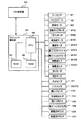
次に、このフィニッシャ500の構成について図2を用いて説明する。
Next, the configuration of the
フィニッシャ500は、複写機本体10からのシートを取り込み、取り込んだ複数のシートを整合して束ねる処理、ソート処理、ノンソート処理を行う他、シート束の後端側をステイプルするステイプル処理(綴じ処理)、製本処理等の処理を行うものである。そして、シートをステイプルするステイプル部600及びシート束を二つ折りにして製本する製本処理部である製本部800を備えている。
The
ここで、ステイプル部600は、シートを積載するシート積載手段としての処理トレイ630と、処理トレイ630上に積載されたシート束に対して幅方向の整合を行う一対の整合手段である整合板1002とを備えている。また、シート束に対してステイプル処理を施すステイプラ601を備えている。
Here, the
また、製本部800は、製本入口センサ831と、2対のステイプラ810と、シートを積載する製本中間トレイ(以下、製本処理トレイという)830とを備えている。さらに、製本処理トレイ830には中間ローラ803と、可動式のシート位置決め部材816が設けられている。
The
なお、2対のステイプラ810と対向する位置にはアンビル811が設けられており、ステイプラ810とアンビル811が協働して、製本処理トレイ830に収納されたシート束に対してステイプル処理を行える構成となっている。
An
また、ステイプラ810の下流側には、折りローラ対804と、折りローラ対804と対向した位置に突き出し部材815が設けられている。そして、この突き出し部材815を製本処理トレイ830に収納されたシート束に向けて突出することにより、製本処理トレイ830で束状に収納されたシート束を折りローラ対804間に押し出すようにしている。なお、搬送ローラ対804の下流には排紙センサ832が設けられている。
Further, on the downstream side of the
また、このフィニッシャ500は、複写機本体10から搬送されたシートを装置内部に取り込むための入口ローラ対502を備えており、この入口ローラ対502と搬送ローラ対503との間には、入口センサ531が設けられている。
Further, the
さらに、搬送ローラ対503とバッファローラ505との間には、シートをオフセットして排紙するシフトソートモードの際には、シートを幅方向の所定の位置にシフトさせながら搬送するシフト搬送手段である横レジ補正装置1001が設けられている。ここで、この横レジ補正装置1001は、シフトソートモードの際には、フィニッシャ500に取り込まれたシート全てに動作し、シートの横レジを補正すると共にシートを幅方向の所定の位置にシフトさせながら搬送するものである。なお、この横レジ補正装置1001は、搬送ローラ1101a,1102aと、搬送ローラ1101a,1102aに圧接する従動ローラ1101b,1102bとを備えている。
Further, in the shift sort mode in which the sheet is offset and discharged between the conveying
また、横レジ補正装置1001の下流には、搬送ローラ対503及び横レジ補正装置1001を介して搬送されたシートを所定枚数巻き付けることが可能なバッファローラ505が設けられている。そして、シートはバッファローラ505の回転中に押下コロ512,513,514により巻き付けられ、バッファローラ505が回転する方向へ搬送される。
Further, a
なお、押下コロ513,514の間には切り換えフラッパ511が設けられ、さらにその下方には、切り換えフラッパ510が設けられている。ここで、切り換えフラッパ511は、バッファローラ505に巻き付けられたシートをソートパス522に、又はバッファローラ505から剥離してサンプルトレイ701側のノンソートパス521に選択的に導くためのものである。なお、533はノンソートパス521の途中に設けられている排紙センサである。
A switching
また、切り換えフラッパ510は、バッファローラ505に巻き付けられたシートを、バッファローラ505から剥離してソートパス522に導く、或はシートをバッファローラ505に巻き付けられた状態でバッファパス523に選択的に導くためのものである。なお、バッファパス523には、バッファパス523上のシートを検出するためのバッファパスセンサ532が設けられている。
Further, the switching
ソートパス522の下流には切換フラッパ512が配置されており、この切換フラッパ512はソートパス522に導かれたシートをソート排出パス524または製本パス525に導くためのものである。
A switching
ここで、ソート排出パス524に導かれたシートは、搬送ローラ対507を介して処理トレイ630上に積載されて束状となる。そして、この処理トレイ630上に積載されたシート束は、必要に応じて整合処理、ステイプル処理などが施された後に、排出ローラ680a,680bによりスタックトレイ700上に排出される。
Here, the sheets guided to the
この排出ローラ680bは揺動ガイド650に支持され、この揺動ガイド650は不図示の揺動モータにより排出ローラ680bを処理トレイ630上の最上部のシートに当接させるように揺動するようになっている。なお、排出ローラ680bが処理トレイ630上の最上部のシートに当接された状態にあるとき、排出ローラ680bは排出ローラ680aと協働して処理トレイ630上のシート束をスタックトレイ700に向けて排出することが可能である。
The
そして、このような構成のフィニッシャ500において、複写機本体10からシートが排紙されると、シートは、まず入口ローラ対502に受け渡される事になる。なお、この時、入口センサ531によりシートの受渡しタイミングも同時に検知されている。
In the
次に、入口ローラ対502により搬送されたシートは横レジ補正装置1001により幅方向にシフトされながら搬送される。この後、バッファローラ対505に搬送され、バッファローラ505の回転中に押下コロ512,513,514により巻き付けられ、バッファローラ505が回転する方向へ搬送される。なお、横レジ補正装置1001のシフト動作については、後述する。
Next, the sheet conveyed by the
ここで、シートは、ノンソート処理を行う場合は、切り換えフラッパ511によりバッファローラ505から剥離されてノンソートパス521に導かれ、排出ローラ対509を介してサンプルトレイ701上に排出される。
Here, when the non-sort process is performed, the sheet is peeled from the
また、ソート処理、綴じ処理、或は製本処理を行う場合は、シートを所定枚数まとめてステイプル部600等に搬送する。このため、シートは、まず切り換えフラッパ511及び切換フラッパ510によりバッファローラ505に巻き付けられた状態でバッファパス523に送られる。そして、この後、所定枚数のシートが同様にしてバッファローラ505に巻き付けられた状態でバッファパス523に送られる。
In addition, when performing sort processing, binding processing, or bookbinding processing, a predetermined number of sheets are collected and conveyed to the
次に、このように所定枚数のシートがバッファパス523に送られると、このシートは切り換えフラッパ510によりバッファローラ505から剥離されてソートパス522に送られる。そして、このようにソートパス522に搬送されたシートは、搬送ローラ対506を経て切換フラッパ512によりソート排出パス524又は製本パス525に導かれるようになっている。
Next, when a predetermined number of sheets are sent to the
ここで、切り換えフラッパ510によりソート排出パス524に導かれた場合、シートは処理トレイ630上に積載される。そして、処理トレイ630上に束状に積載されたシート群は、図1に示す操作表示装置400からの設定に応じて、一対の整合板1002による整合処理や、ステイプラ601によるステイプル処理が行なわれる。
Here, when the sheet is guided to the
この後、整合板1002の整合処理、ステイプラ601によるステイプル処理が行なわれたシート束毎にスタックトレイ700に排出ローラ580a、580bによって排出される。シフトソートモードのときもシート束毎に整合板1002によって整合してスタックトレイ700に排出ローラ580a、580bによって排出される。
Thereafter, each sheet bundle subjected to alignment processing of the
なお、このステイプル処理は、ステイプラ601により行われるが、このステイプラ601は、処理トレイ630の外周に沿って移動可能に構成されている。これにより、処理トレイ630に積載されたシート束を、シート搬送方向(図2中左方向)に対してシートの最後尾位置(後端)で綴じることができる。
The stapling process is performed by the stapler 601. The stapler 601 is configured to be movable along the outer periphery of the
また、切り換えフラッパ510により製本パス525に導かれたシートは、搬送ローラ対802を介して製本中間トレイ830に搬送され、ステイプラ810とアンビル811によりステイプル処理が施される。この後、突き出し部材815により折りローラ対804間に押し出されることにより、シート束は折られ、さらに折りローラ対804により下流へと搬送される。そして、折り込まれたシート束は、搬送ローラ対805を介して排紙トレイ850に排出される。
Further, the sheet guided to the
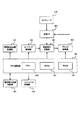
図3は、フィニッシャ500を含む複写機全体の制御ブロック図であり、図3において、150は、CPU回路部である。このCPU回路部150は、CPU150A、ROM151、RAM152を内蔵し、ROM151に格納されている制御プログラムにより各ブロック101,201,202,209,301,401,701を総括的に制御するものである。RAM152は、制御データを一時的に保持し、また制御に伴う演算処理の作業領域として用いられる。
FIG. 3 is a control block diagram of the entire copying machine including the
原稿給送装置制御部101は、原稿給送装置100をCPU回路部150からの指示に基づき駆動制御するものである。また、イメージリーダ制御部201は、既述したスキャナ200のスキャナユニット104、イメージセンサ109などに対する駆動制御を行い、イメージセンサ109から出力されたアナログ画像信号を画像信号制御部202に転送するものである。
The document
画像信号制御部202は、イメージセンサ109からのアナログ画像信号をデジタル信号に変換した後に各処理を施し、このデジタル信号をビデオ信号に変換してプリンタ制御部301に出力するものである。また、外部のコンピュータ210から外部I/F209を介して入力されたデジタル画像信号に各種処理を施し、このデジタル画像信号をビデオ信号に変換してプリンタ制御部301に出力するものである。なお、この画像信号制御部202による処理動作は、CPU回路部150により制御される。
The image
プリンタ制御部301は、画像信号制御部202から入力されたビデオ信号に基づき露光制御部110を駆動するものであり、操作表示装置制御部401は、図1に示す操作表示装置400とCPU回路部150との間で情報のやり取りを行うものである。そして、操作表示装置制御部401は、操作表示装置400からの各キーの操作に対応するキー信号をCPU回路部150に出力すると共に、CPU回路部150からの信号に基づき対応する情報を操作表示装置400の表示部に表示するものである。
The
フィニッシャ制御部501は、例えばフィニッシャ500に搭載され、CPU回路部150と情報のやり取りを行うことによってフィニッシャ全体の駆動制御を行うものである。なお、このフィニッシャ制御部501は複写機本体10に設けても良い。
The
図4は、このようなフィニッシャ制御部501の制御ブロック図であり、このフィニッシャ制御部501は、CPU550、ROM551、RAM552などで構成される。そして、不図示の通信ICを介して複写機本体10側のCPU回路部150と通信してデータ交換を行い、CPU回路部150からの指示に基づきROM552に格納されている各種プログラムを実行してフィニッシャ500の駆動制御を行うようになっている。
FIG. 4 is a control block diagram of such a
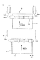
図5は、横レジ補正装置1001の構成を示す概略図であり、図5において、M1103は搬送モータである。そして、この搬送モータM1103により、タイミングベルト1115及び1116介して搬送ローラ1101a,1102aに駆動を与え、従動ローラ(1101b、1102b)と共にシートの搬送を行うようになっている。
FIG. 5 is a schematic diagram showing the configuration of the lateral
1104は搬送されてくるシート端部の位置を検出する位置検知手段である横レジセンサである。この横レジセンサ1104は、横レジセンサシフトモータM1106によって矢印1300に示すように左右に移動する横レジセンサユニット1105に実装されている。なお、この横レジセンサユニット1105のホームポジションは、横レジHPセンサ1108により検出されるようになっている。
1107は横レジセンサユニット1105とは別体の横レジ補正装置1001を矢印1301に示すように左右に駆動させる横レジ補正装置シフトモータである。そして、この横レジ補正装置1001のホームポジションは、横レジ補正装置HPセンサ1109により検出されるようになっている。なお、1112は、後端検知センサであり、この後端検知センサ1112により、搬送されてきたシートを検知すると共に、シートの後端が横レジ補正装置1001内の搬送ローラ1101a,1101bを抜けたことを検知するようにしている。
Reference numeral 1107 denotes a lateral registration correction device shift motor that drives a lateral
次に、このように構成された横レジ補正装置1001の横レジ補正動作について説明する。
Next, the lateral registration correcting operation of the lateral
まず、図6及び図7を用いて搬送パス内で左にシートを移動させて補正する場合について説明する。 First, a case where correction is performed by moving the sheet to the left in the conveyance path will be described with reference to FIGS. 6 and 7.
まず、図6の(a)に示すようにシートPが搬送されてくると、横レジセンサシフトモータM1106が駆動される。これにより、横レジセンサユニット1105が、ホームポジションから矢印に示す左方向へシートサイズにオフセット量を加味した所定の待機位置まで移動する。
First, when the sheet P is conveyed as shown in FIG. 6A, the lateral registration sensor shift motor M1106 is driven. As a result, the lateral
次に、図6の(b)に示すようにシートPが横レジ補正装置1001内に入り、横レジセンサ1104によって検知されると、横レジ補正装置シフトモータM1107が駆動され、横レジ補正装置1001が図7の(a)の矢印で示す左方向に移動する。これに伴いシートPは、搬送されながら左方向に移動し、やがてシートPの側端が横レジセンサ1104を通過し、これにより横レジセンサ1104がシートPを検知しなくなる。
Next, as shown in FIG. 6B, when the sheet P enters the lateral
そして、このように横レジセンサ1104がシートPを検知しなくなると、言い換えれば横レジセンサ1104によりシートPの端部を検出すると、横レジ補正装置シフトモータM1107を停止させる。この動作により、シートPは、横レジが補正され、P’に示す所定の位置にシフトする。
When the
なお、この後、シートPが搬送され、後端検知センサ1112がシートPの後端を検知すると、横レジ補正装置シフトモータM1107によって横レジ補正装置1001を図7の(b)の矢印に示す右方向に移動させ、図6に示すホームポジションまで戻す。
After this, when the sheet P is conveyed and the trailing
次に、図8及び図9を用いて搬送パス内で右にシートを移動させて補正する場合について説明する。 Next, a case where correction is performed by moving the sheet to the right in the conveyance path will be described with reference to FIGS. 8 and 9.
まず、図8の(a)に示すようにシートPが搬送されてくると、横レジセンサシフトモータM1106が駆動される。これにより、横レジセンサユニット1105が、ホームポジションから矢印で示す左方向へシートサイズにオフセット量を加味した所定の待機位置まで移動する。
First, as shown in FIG. 8A, when the sheet P is conveyed, the lateral registration sensor shift motor M1106 is driven. As a result, the lateral
次に、図8の(b)に示すようにシートPが横レジ補正装置1001内に入り、後端検知センサ1112により先端が検知されると、横レジ補正装置シフトモータM1107が駆動され、横レジ補正装置1001が図9の(a)の矢印で示す右方向に移動する。
Next, as shown in FIG. 8B, when the sheet P enters the lateral
これに伴いシートPは、搬送されながら右方向に移動し、やがてシートPの側端が横レジセンサ1104により検知される。そして、このように横レジセンサ1104がシートPの端部を検出すると、横レジ補正装置シフトモータM1107を停止させる。この動作により、シートPは、横レジが補正され、P’に示す所定の位置にシフトする。
Along with this, the sheet P moves rightward while being conveyed, and the side edge of the sheet P is eventually detected by the
なお、この後、シートPが搬送され、後端検知センサ1112がシートPの後端を検知すると、横レジ補正装置シフトモータM1107によって横レジ補正装置1001を図9の(b)の矢印に示す左方向に移動させ、図8に示すホームポジションまで戻す。
Thereafter, when the sheet P is conveyed and the trailing
ところで、本実施の形態においては、このように横レジ補正装置1001により横レジ補正動作を行った後、シートをフィニッシャ500の処理トレイ630に搬送し、この処理トレイ630において整合動作を行うようにしている。
By the way, in the present embodiment, after the lateral registration correction operation is performed by the lateral
図10は、処理トレイ630の構成を示す図である。図10において、M3は排紙モータであり、この排紙モータM3から駆動を与えられた搬送ローラ対507によって、処理トレイ630上にシートが排紙される。
FIG. 10 is a diagram illustrating a configuration of the
また、M1202、M1201は、前整合モータ及び後整合モータであり、これら前整合モータM1202及び後整合モータM1201によって処理トレイ630上に排紙されたシートを整合する前整合板1002a及び後整合板1002bは駆動される。そして、この一対の整合板を構成すると共に、それぞれ独立して駆動される前整合板1002a及び後整合板1002bが、矢印1400、1401方向に駆動されることにより、シートが整合される。なお、1202、1203は前整合板1002a及び後整合板1002bの、それぞれのホームポジションを検出する前整合HPセンサ及び後整合HPセンサである。
M1202 and M1201 are a front alignment motor and a rear alignment motor, and a
次に、本実施の形態に係る整合動作について説明するが、その前に横レジ補正装置1001により横レジ補正が行われなかった場合のシフトソートモードにおける整合動作について図11及び図12を用いて説明する。
Next, the alignment operation according to the present embodiment will be described. Prior to that, the alignment operation in the shift sort mode when the horizontal registration correction is not performed by the horizontal
なお、本実施の形態において、シフトソートモードが選択された場合、処理トレイ630上に搬送されたシートPは、束オフセット量Laだけシフトした位置に整合された後に、排紙トレイ700上排出される。このシフトの方向をシート束毎に前側と後側に切り換えることにより、仕分け積載が可能となる。
In this embodiment, when the shift sort mode is selected, the sheet P conveyed on the
まず、図11の(a)に示すように、シフトソートモードが選択されると、前整合板1002a及び後整合板1002bは、装置中心位置でのシート幅Lpに対して束オフセット量Laの分、外側に移動した位置で待機する。なお、このとき束オフセット量Laは、複写機本体10から排出されたときの横レジズレ量をLb、フィニッシャ500内で搬送中に発生する横レジズレ量をLcとした場合、これらの横レジズレ量を加算した量よりも大きくなるように設定されている。即ちLa>Lb+Lcの関係にある。
First, as shown in FIG. 11A, when the shift sort mode is selected, the
これにより、横レジズレ量(Lb+Lc)が最大になった場合でも、待機位置にある整合板1002a,1002bに対して、処理トレイ630上に搬送されるシートPが衝突して搬送不良を引き起こすことは無い。
As a result, even when the lateral misregistration amount (Lb + Lc) is maximized, the sheet P conveyed on the
ここで、例えばシートPを前側にLaだけオフセットして整合する場合は、図11の(b)に示すように、前整合板1002aは、待機位置で停止したまま基準としての役割を果たす。そして、シートPが処理トレイ630に入った後に、後整合板1002bがオフセット量Laの略2倍の距離を往復動作することで、この基準となる前整合板1002aに対してシートPを片側基準で整合させる。
Here, for example, when the sheet P is aligned by being offset by La to the front side, as shown in FIG. 11B, the
また、シート束が切り替わり、シートPを後側にLaだけオフセットして整合する場合は、図12に示すように、後整合板1002bが待機位置で停止したまま基準としての役割を果たす。そして、シートPが処理トレイ630に入った後に、前整合板1002aがオフセット量Laの略2倍の距離を往復動作することで、基準となる後整合板1002bに対してシートを片側基準で整合させる。
Further, when the sheet bundle is switched and the sheet P is aligned by being offset by La to the rear side, as shown in FIG. 12, the
次に、フィニッシャ500内で横レジ補正を行うようにした場合のシフトソートモードにおける整合動作について図13及び図14を用いて説明する。
Next, the alignment operation in the shift sort mode when the lateral registration correction is performed in the
図13の(a)は、シート束を前側にオフセット整合する場合の整合板1002a,1002bの待機位置を示した図である。ここで、処理トレイ630上に搬送されるシートPは、前述した横レジ補正装置1001の動作により、画像形成装置10から排出されたときの横レジズレ量Lbが補正された上に、束オフセット量Laの分、横レジ量がシフトされた状態にある。そして、横レジ補正装置1001によって、オフセットされて図13に示している前側の積載位置(第1積載位置)に積載される。
FIG. 13A is a diagram showing standby positions of the
よって、処理トレイ630上での整合板1002a,1002bの整合距離Ldは、フィニッシャ500内の横レジ補正装置1001から処理トレイ630までに至る搬送路中で生したズレ量Leよりわずかに大きくなる程度に設定しておけば(Ld>Le)良い。これにより、待機する整合板1002a,1002bに対して、処理トレイ630上に搬送されるシートPが衝突して搬送不良を引き起こすことは無い。
Therefore, the alignment distance Ld of the
また、シートPが処理トレイ630上に搬送された後は、図13の(b)に示すように、前整合板1002a及び後整合板1002bを各々整合距離Ldの分だけ往復動作させれば、オフセット位置においてシートPのセンター整合が行われる。つまり、整合板1002a,1002bは前側の積載位置に対応した待機位置から、処理トレイ630に積載されたシート束の整合を行う。そして、整合処理されたシート束は、スタックトレイ700に排出ローラ580a、580bによって排出される。
Further, after the sheet P is conveyed onto the
なお、後側にオフセット整合する場合も同様で、図14に示すように、基準となるオフセットセンター位置を前側と後側で切り換えるだけで同様な整合を行うことができる。即ち、横レジ補正装置1001によってオフセットされて図14に示している後側の積載位置(第2積載位置)にシートは積載される。 The same applies to the case where offset matching is performed on the rear side. As shown in FIG. 14, the same alignment can be performed only by switching the reference offset center position between the front side and the rear side. In other words, the sheets are stacked at the rear stacking position (second stacking position) shown in FIG.
図13に示す前側の積載位置に対して図14の後側の積載位置は所定のオフセット量だけオフセットされた位置である。後側の積載位置にシート束が積載されるときには、図14に示した、後側の積載位置に対応した待機位置に整合板1002a,1002bは待機している。
The rear loading position in FIG. 14 is offset from the front loading position shown in FIG. 13 by a predetermined offset amount. When the sheet bundle is stacked at the rear stacking position, the
整合板1002a,1002bは後側の積載位置に対応した待機位置から、処理トレイ630に積載されたシート束の整合を行う。この際の整合距離に関しては既述の前側にオフセットさせた図13に示した時と同様であるために説明を省略する。そして、整合処理されたシート束は、スタックトレイ700に排出ローラ580a、580bによって排出される。
The
例えば、シフトソートモードが選択された場合には、先行するシート束を図13における前側の積載位置で整合してスタックトレイ700に排出し、後続するシート束を図14に示す後側の積載位置で整合してスタックトレイ700に排出する動作を繰り返す。この動作によってシート束毎にオフセットされた状態でスタックトレイ700に積載される。
For example, when the shift sort mode is selected, the preceding sheet bundle is aligned at the front stacking position in FIG. 13 and discharged to the
ところで、この実施の形態では、前整合モータM1202及び後整合モータM1201は、ステッピングモータを使用しており、また自起動駆動させている。前整合モータM1202及び後整合モータM1201の駆動速度をVとすると、整合動作に要する時間Tは、1往復で
図11及び図12の場合、
T=2*2*La/V
と表すことができる。
By the way, in this embodiment, the front alignment motor M1202 and the rear alignment motor M1201 use stepping motors and are self-startingly driven. If the driving speeds of the front alignment motor M1202 and the rear alignment motor M1201 are V, the time T required for the alignment operation is one reciprocation in the case of FIGS.
T = 2 * 2 * La / V
It can be expressed as.
図13及び図14の場合、
T=2*Ld/V
と、表すことができる。ここで、La≫Ldであるから、本実施の形態に係る横レジ補正を行うことで、
ΔT=2*2*La/V−2*Ld/V
だけ時間を短縮することが可能となる。
In the case of FIG. 13 and FIG.
T = 2 * Ld / V
It can be expressed as. Here, since La >> Ld, by performing the lateral registration correction according to the present embodiment,
ΔT = 2 * 2 * La / V-2 * Ld / V
Only time can be shortened.
このように、処理トレイ630に所定の位置であるオフセット位置にシフトさせた状態でシートPを積載する。シートのシフトは横レジ補正装置1001によって行う。整合板1002a,1002bを予めシートのオフセット位置に応じた位置に移動させる。
Thus, the sheets P are stacked on the
上述の実施の形態に基づいて具体的に記せば、処理トレイ630における前側の積載位置に積載するときには前側の積載位置に応じた位置に予め整合板1002a,1002bを移動させる。後側の積載位置に積載するときには後側の積載位置に応じた位置に予め整合板1002a,1002bを移動させる。
More specifically, the
さらに、整合板1002a,1002bの幅方向の間隔をシートをシフトさせないときの間隔よりも狭めた状態とすることにより、整合動作の時間を短縮することができ、高生産性を達成することが可能となる。
Furthermore, by making the interval in the width direction of the
また、本実施の形態のように横レジ補正を行った場合は、フィニッシャ500内の横レジ補正装置1001から処理トレイ630に至る搬送路中で生じた横レジズレ量Leよりわずかに大きく設定するだけで良くなる。したがって、オフセット量Laを複写機本体10の横レジズレ量Lbとフィニッシャ500内での横レジズレ量Lcを加算した量より大きく設定する必要があった。
Further, when the lateral registration correction is performed as in the present embodiment, the lateral registration correction amount Le is set slightly larger than the lateral registration amount Le generated in the transport path from the lateral
したがって、オフセット量の少ない側の設定幅の自由度が広がり、よりユーザにとって使い勝手の良い、より高生産性の向上されたフィニッシャ500およびこれを備える画像形成装置を提供することが可能となる。
Therefore, it is possible to provide a
例えば、シート幅に対してオフセット量の占める割合が大きく、積載されたシート束が崩れ易くなる可能性の高い小サイズのシートの場合には、他のシートサイズに対して、オフセット量を少なく設定するようにすれば良い。 For example, in the case of a small size sheet that has a high ratio of the offset amount to the sheet width and is likely to collapse the stacked sheet bundle, the offset amount is set to be smaller than other sheet sizes. You should do it.
これにより、より多量のシートを整合性の良い状態で積載することが可能になり、満載の上限が増すと共に、シート束が崩れにくくなる。この結果、1ジョブ当たりの処理部数を多く設定することが可能となると共に、シート束が崩れることによるシステムとしてのダウンタイムが削減され、より生産性を向上することが可能になる。 As a result, a larger amount of sheets can be stacked with good consistency, and the upper limit of the full load is increased, and the sheet bundle is not easily broken. As a result, it is possible to set a large number of copies per job, reduce the downtime of the system due to the collapse of the sheet bundle, and further improve productivity.
また、ステイプルモードによっても、ステイプル針が折り重なることにより前奥の高低差が生じやすい1箇所綴じ対して、1箇所綴じと比較すると前奥の高低差が生じにくい2箇所綴じの場合には、オフセット量を少なく設定するようにすれば良い。これにより、ステイプラを移動する時間の分だけ生産性に不利な条件にある2箇所綴じの生産性を向上することが可能になる。 Also, in the case of two-point binding where the front-rear height difference is less likely to occur compared to the one-point binding compared to the one-point binding, which is likely to cause a front-rear height difference due to folding of the staples even in the staple mode. A small amount may be set. As a result, it is possible to improve the productivity of the two-point binding, which is in a condition that is disadvantageous to the productivity, for the time required to move the stapler.
ところで、本実施の形態においては、横レジ補正装置1001に何らかの異常が発生した場合には、横レジ補正の機能のみ切り離すことができるようにしている。
By the way, in the present embodiment, when any abnormality occurs in the lateral
次に、このようなモードである横レジ補正の冗長モードについて図15に示すフローチャートに基づいて説明する。 Next, a redundancy mode for lateral registration correction which is such a mode will be described with reference to a flowchart shown in FIG.
フィニッシャ500に電源が投入されると、負荷の動作チェックのため、モータのイニシャル動作が行われる。これに伴いCPU550は、横レジ補正装置1001を移動させるよう横レジ補正装置シフトモータM1107の駆動信号を出す。そして、異常検知手段である横レジ補正装置HPセンサ1109の信号に変化があるか監視し、横レジ補正装置1001の異常の発生の有無を検知する(S101)。
When power is turned on to the
ここで、横レジ補正装置1001が移動すれば、即ち横レジ補正装置1001に異常がなければ、横レジ補正装置HPセンサ1109の信号に変化があり、この場合、横レジ補正装置1001に異常が発生していないと判断する。そして、このように横レジ補正装置1001に異常が発生していないと判断した場合には(S101のN)、整合動作を第1の処理、即ち既述した横レジ補正を含む第1の処理に設定する(S102)。この後、横レジ補正を含む第1の整合動作を行う(S103)。
Here, if the lateral
一方、横レジ補正装置HPセンサ1109の信号に変化がなく、横レジ補正装置1001に異常が発生していると判断した場合には(S101のY)、横レジ補正装置1001に何らかの異常が発生したとみなし、横レジ補正の冗長モードに入る。
On the other hand, if there is no change in the signal of the lateral registration correction
そして、このように冗長モードに入ると、横レジ補正装置シフトモータM1107及び横レジセンサシフトモータM1106の電源をシャットダウンする(S104)。次に、整合動作を第2の処理、即ち既述した横レジ補正動作を行わない第2の処理に設定する(S105)。 When the redundancy mode is entered in this way, the power sources of the lateral registration correction device shift motor M1107 and the lateral registration sensor shift motor M1106 are shut down (S104). Next, the alignment operation is set to the second processing, that is, the second processing that does not perform the lateral registration correction operation described above (S105).
この後、横レジ補正を含まない第2の整合動作を行う(S106)。なお、この第2の整合動作は、既述した図11及び図12に示す横レジ補正装置1001により横レジ補正が行われなかった場合の動作と同じである。
Thereafter, a second alignment operation that does not include lateral registration correction is performed (S106). The second alignment operation is the same as the operation in the case where the lateral registration correction is not performed by the lateral
このように、横レジ補正装置1001に異常が発生している場合には、横レジ補正の機能のみ切り離し、通常の動作を継続させる冗長モードに切り換えるように制御することにより、システムとしてのダウンタイムを避けることができる。これにより、高生産性を達成することができる。
As described above, when an abnormality has occurred in the lateral
次に、本発明の第2の実施の形態について説明する。 Next, a second embodiment of the present invention will be described.
なお、本実施の形態においては、シート束をオフセットすることなく、排出するようにしている。したがって、横レジ補正装置1001による横レジ補正動作の際、横レジセンサユニット1105の待機位置(例えば、図6及び図8参照)は、オフセット量を加味することのない、ホームポジションからシートサイズに応じた所定の位置となる。
In the present embodiment, the sheet bundle is discharged without being offset. Therefore, during the lateral registration correction operation by the lateral
次に、本実施の形態に係るシート処理装置であるフィニッシャの整合動作について説明するが、その前に横レジ補正装置1001により横レジ補正が行われなかった場合の整合動作について図16及び図17を用いて説明する。
Next, a description will be given of the aligning operation of the finisher which is the sheet processing apparatus according to the present embodiment. Prior to that, the aligning operation when the lateral registration correction is not performed by the lateral
この場合、前整合板1002a及び後整合板1002bは、図16の(a)に示すように、複写機本体10から排出されたシートP2が排出された時、横レジズレ量及びフィニッシャ内で搬送中に発生するズレ量を考慮した位置で待機している。なお、この待機位置は、シートPが理想的に横レジ補正された位置に対して、最大L22分ズレても整合動作可能となる位置である。
In this case, as shown in FIG. 16A, the
次に、図16の(b)に示すように、シートP2が処理トレイ630に入ってくると、前整合板1002a及び後整合板1002bは、シートサイズに応じた位置1002a−1,1002b−1へと移動する。この後、処理トレイ630上にシートP2が積載されると、そのつど前整合板1002a及び後整合板1002bは、図17に示すように押圧位置1002a−2,1002b−2へL12だけ往復移動し、シートPの整合を行う。
Next, as shown in FIG. 16B, when the sheet P2 enters the
次に、フィニッシャ500内で横レジ補正を行うようにした場合の整合動作について図18及び図19を用いて説明する。
Next, the alignment operation when the lateral registration correction is performed in the
この場合、図18の(a)に示すように、シートP1の横レジズレは、フィニッシャ内で横レジ補正されたので、横レジ補正装置1001から処理トレイ630までシート搬送中に発生する横レジズレを考慮すれば良い。このため、理想の横レジ補正されたシートPに対して、L22より小さいL21だけで良いことになる。
In this case, as shown in FIG. 18A, since the lateral registration of the sheet P1 has been subjected to the lateral registration correction in the finisher, the lateral registration that occurs during sheet conveyance from the lateral
次に、図18の(b)に示すように、シートが処理トレイ630に入ってくると、前整合板1002a及び後整合板1002bは、シートサイズに応じた位置1002a−1,1002b−1へ移動する。
Next, as shown in FIG. 18B, when a sheet enters the
この後、処理トレイ630上にシートP2が積載されると、そのつど前整合板1002a及び後整合板1002bは、図19に示すように押圧位置1002a−2,1002b−2へL11だけ往復移動し、シートの整合を行う。
Thereafter, when the sheet P2 is stacked on the
ところで、この実施の形態では、前整合モータM1202及び後整合モータM1201は、ステッピングモータを使用しており、また自起動駆動させている。前整合モータM1202及び後整合モータM1201の駆動速度をVとすると、整合動作に掛かる時間Tは、1往復で
図16及び図17の場合、
T=2*L12/V
図18及び図19の場合、
T=2*L11/V
と、それぞれ表すことができる。ここで、L12>L11であるから、本実施の形態に係る横レジ補正を行うことで、
ΔT=2*L12/V−2*L11/V
だけ、時間を短縮することが可能となる。
By the way, in this embodiment, the front alignment motor M1202 and the rear alignment motor M1201 use stepping motors and are self-startingly driven. When the driving speeds of the front alignment motor M1202 and the rear alignment motor M1201 are V, the time T required for the alignment operation is one reciprocation in the case of FIGS.
T = 2 * L12 / V
In the case of FIG. 18 and FIG.
T = 2 * L11 / V
And can be expressed respectively. Here, since L12> L11, by performing the lateral registration correction according to the present embodiment,
ΔT = 2 * L12 / V-2 * L11 / V
Only time can be shortened.
このように、整合板1002a,1002bの幅方向の間隔をシートをシフトさせないときの間隔よりも狭めた状態とすることにより、整合動作の時間を短縮することができ、高生産性を達成することが可能となる。
Thus, by setting the interval in the width direction of the
10 複写機本体
400 操作表示装置
500 フィニッシャ(シート処理装置)
600 ステイプル部
630 処理トレイ
1000 複写機
1002 整合板
1001 横レジ補正装置
1104 横レジセンサ
1109 横レジ補正装置HPセンサ
P シート
10
600
Claims (7)
シート搬送方向と直交する幅方向にそれぞれ独立して移動可能に設けられ、前記シート積載手段に積載されたシートの両側に当接して該シートの幅方向の整合を行う一対の整合手段と、
前記シート積載手段のシート搬送方向上流側に設けられ、シートを幅方向にシフトさせて搬送するシフト搬送手段と、
搬送されるシートのシート搬送方向に沿った端部の位置を検出する位置検出手段と、を備え、
シートは前記シフト搬送手段によってシフトされて前記シート積載手段における第1積載位置と、前記第1積載位置と前記幅方向で位置が異なる第2積載位置とに積載され、
前記シフト搬送手段は、前記位置検出手段により検出されたシートの端部の位置に応じてシートを幅方向にシフトさせ、
前記第1積載位置にシートが積載されるときには予め前記一対の整合手段は前記第1積載位置に積載されるシートの幅方向両側近傍の第1待機位置に移動され、前記第2積載位置にシートが積載されるときには予め前記一対の整合手段は前記幅方向で前記第1待機位置と異なった位置であって、前記第2積載位置に積載されるシートの幅方向両端近傍の第2待機位置に移動されることを特徴とするシート処理装置。 In the sheet processing apparatus for aligning the sheets stacked on the sheet stacking means,
A pair of aligning means provided so as to be independently movable in the width direction orthogonal to the sheet conveying direction, and abutting on both sides of the sheets stacked on the sheet stacking means to align the sheets in the width direction;
A shift conveying means that is provided upstream of the sheet stacking means in the sheet conveying direction, and that shifts and conveys the sheet in the width direction;
Position detecting means for detecting the position of the end portion along the sheet conveying direction of the conveyed sheet ,
The sheets are shifted by the shift conveying unit and stacked at a first stacking position in the sheet stacking unit and a second stacking position having a position different from the first stacking position in the width direction ,
The shift conveying unit shifts the sheet in the width direction according to the position of the end of the sheet detected by the position detecting unit,
When the sheets are stacked at the first stacking position, the pair of aligning means is moved in advance to the first standby positions in the vicinity of both sides in the width direction of the sheets stacked at the first stacking position, and the sheets are moved to the second stacking position. When the sheets are stacked in advance, the pair of aligning means is in a position different from the first standby position in the width direction, and at a second standby position in the vicinity of both ends in the width direction of the sheets stacked at the second stack position. A sheet processing apparatus that is moved.
前記異常検知手段が前記シフト搬送手段の異常を検知した場合には、前記一対の整合手段の間隔を、前記シートをシフトさせないときの間隔に設定することを特徴とする請求項2に記載のシート処理装置。 Comprising an abnormality detection means for detecting the presence or absence of abnormality of the shift conveying means,
3. The sheet according to claim 2 , wherein when the abnormality detection unit detects an abnormality of the shift conveyance unit, the interval between the pair of alignment units is set to an interval when the sheet is not shifted. Processing equipment.
前記画像形成部で画像が形成されたシートが積載されるシート積載手段と、
シート搬送方向と直交する幅方向にそれぞれ独立して移動可能に設けられ、前記シート積載手段に積載されたシートの両側に当接して該シートの幅方向の整合を行う一対の整合手段と、
前記シート積載手段のシート搬送方向上流側に設けられ、シートを幅方向にシフトさせて搬送するシフト搬送手段と、
搬送されるシートのシート搬送方向に沿った端部の位置を検出する位置検出手段と、を備え、
シートは前記シフト搬送手段によってシフトされて前記シート積載手段における第1積載位置と、前記第1積載位置と前記幅方向で位置が異なる第2積載位置とに積載され、
前記シフト搬送手段は、前記位置検出手段により検出されたシートの端部の位置に応じてシートを幅方向にシフトさせ、
前記第1積載位置にシートが積載されるときには予め前記一対の整合手段は前記第1積載位置に積載されるシートの幅方向両側近傍の第1待機位置に移動され、前記第2積載位置にシートが積載されるときには予め前記一対の整合手段は、前記幅方向で前記第1待機位置と異なった位置であって、前記第2積載位置に積載されるシートの幅方向両側近傍の第2待機位置に移動されることを特徴とする画像形成装置。 An image forming unit;
Sheet stacking means for stacking sheets on which images are formed in the image forming unit;
A pair of aligning means provided so as to be independently movable in the width direction orthogonal to the sheet conveying direction, and abutting on both sides of the sheets stacked on the sheet stacking means to align the sheets in the width direction;
A shift conveying means that is provided upstream of the sheet stacking means in the sheet conveying direction, and that shifts and conveys the sheet in the width direction;
Position detecting means for detecting the position of the end of the conveyed sheet along the sheet conveyance direction, and
The sheets are shifted by the shift conveying unit and stacked at a first stacking position in the sheet stacking unit and a second stacking position having a position different from the first stacking position in the width direction,
The shift conveying unit shifts the sheet in the width direction according to the position of the end of the sheet detected by the position detecting unit,
When the sheets are stacked at the first stacking position, the pair of aligning means is moved in advance to the first standby positions in the vicinity of both sides in the width direction of the sheets stacked at the first stacking position, and the sheets are moved to the second stacking position. When the sheets are stacked in advance, the pair of aligning means is a second standby position that is different from the first standby position in the width direction and is near both sides in the width direction of the sheets stacked at the second stack position. an image forming apparatus characterized in that it is moved to.
Priority Applications (5)
| Application Number | Priority Date | Filing Date | Title |
|---|---|---|---|
| JP2005266112A JP4307429B2 (en) | 2005-09-13 | 2005-09-13 | Sheet processing apparatus and image forming apparatus |
| US11/530,792 US7581725B2 (en) | 2005-09-13 | 2006-09-11 | Sheet processing apparatus |
| EP06120485.5A EP1762522B1 (en) | 2005-09-13 | 2006-09-12 | Sheet processing apparatus |
| US12/506,050 US7866652B2 (en) | 2005-09-13 | 2009-07-20 | Sheet processing apparatus |
| US15/072,221 USRE46875E1 (en) | 2005-09-13 | 2016-03-16 | Sheet processing apparatus |
Applications Claiming Priority (1)
| Application Number | Priority Date | Filing Date | Title |
|---|---|---|---|
| JP2005266112A JP4307429B2 (en) | 2005-09-13 | 2005-09-13 | Sheet processing apparatus and image forming apparatus |
Publications (2)
| Publication Number | Publication Date |
|---|---|
| JP2007076800A JP2007076800A (en) | 2007-03-29 |
| JP4307429B2 true JP4307429B2 (en) | 2009-08-05 |
Family
ID=37526970
Family Applications (1)
| Application Number | Title | Priority Date | Filing Date |
|---|---|---|---|
| JP2005266112A Expired - Fee Related JP4307429B2 (en) | 2005-09-13 | 2005-09-13 | Sheet processing apparatus and image forming apparatus |
Country Status (3)
| Country | Link |
|---|---|
| US (3) | US7581725B2 (en) |
| EP (1) | EP1762522B1 (en) |
| JP (1) | JP4307429B2 (en) |
Cited By (1)
| Publication number | Priority date | Publication date | Assignee | Title |
|---|---|---|---|---|
| US9096091B2 (en) | 2012-12-03 | 2015-08-04 | Ricoh Company, Limited | Postprocessing apparatus, and image forming apparatus and image forming system including the postprocessing apparatus |
Families Citing this family (20)
| Publication number | Priority date | Publication date | Assignee | Title |
|---|---|---|---|---|
| JP4785474B2 (en) * | 2005-09-13 | 2011-10-05 | キヤノン株式会社 | Sheet processing apparatus and image forming apparatus |
| JP4819636B2 (en) * | 2005-12-01 | 2011-11-24 | キヤノン株式会社 | Sheet processing apparatus and image forming apparatus |
| US7747212B2 (en) * | 2007-02-01 | 2010-06-29 | Toshiba Tec Kabushiki Kaisha | Sheet processing apparatus and sheet processing method |
| US7665729B2 (en) * | 2007-06-19 | 2010-02-23 | Kabushiki Kaisha Toshiba | Sheeting processing apparatus |
| JP2009113924A (en) * | 2007-11-07 | 2009-05-28 | Canon Inc | Sheet discharge apparatus, sheet processing apparatus, and image forming apparatus |
| JP5247140B2 (en) * | 2007-12-26 | 2013-07-24 | キヤノン株式会社 | Sheet conveying apparatus and control method thereof |
| US8308154B2 (en) * | 2008-02-25 | 2012-11-13 | Canon Kabushiki Kaisha | Image forming apparatus, image forming system, and control method therefor |
| JP5267231B2 (en) * | 2009-03-11 | 2013-08-21 | コニカミノルタビジネステクノロジーズ株式会社 | Punching device, post-processing device and image forming system |
| JP5578830B2 (en) * | 2009-10-21 | 2014-08-27 | キヤノン株式会社 | Sheet processing apparatus, image forming apparatus, and control method for image forming system |
| JP5578933B2 (en) * | 2010-05-18 | 2014-08-27 | キヤノン株式会社 | Sheet processing apparatus and image forming system |
| JP5047339B2 (en) * | 2010-07-23 | 2012-10-10 | シャープ株式会社 | Image forming apparatus |
| JP5972095B2 (en) * | 2011-08-08 | 2016-08-17 | キヤノン株式会社 | Sheet processing apparatus and control method thereof |
| JP6128829B2 (en) * | 2012-01-10 | 2017-05-17 | キヤノン株式会社 | Post-processing apparatus and control method thereof |
| JP5997495B2 (en) * | 2012-05-01 | 2016-09-28 | キヤノン株式会社 | Sheet conveying apparatus and image forming system having the same |
| JP5966614B2 (en) * | 2012-05-25 | 2016-08-10 | 富士ゼロックス株式会社 | Sheet processing apparatus and image forming system |
| JP6037303B2 (en) * | 2012-06-29 | 2016-12-07 | ニスカ株式会社 | Sheet alignment apparatus and image forming system provided with the same |
| EP3068977B1 (en) | 2013-11-14 | 2019-07-10 | United Technologies Corporation | Gas turbine vane assembly comprising a rotatable vane with protrusions on the pressure or suction side |
| JP6292873B2 (en) * | 2013-12-27 | 2018-03-14 | キヤノン株式会社 | Sheet processing apparatus and image forming system |
| US10562731B2 (en) * | 2016-12-09 | 2020-02-18 | Canon Finetech Nisca Inc. | Apparatus for processing sheets and apparatus for forming images provided with the apparatus |
| US10604369B2 (en) * | 2016-12-09 | 2020-03-31 | Canon Finetech Nisca Inc. | Apparatus for processing sheets and apparatus for forming images provided with the apparatus |
Family Cites Families (16)
| Publication number | Priority date | Publication date | Assignee | Title |
|---|---|---|---|---|
| JPS6178163A (en) | 1984-09-26 | 1986-04-21 | Hitachi Ltd | Manufacture of semiconductor device |
| US5263697A (en) * | 1989-04-18 | 1993-11-23 | Ricoh Company, Ltd. | Finisher for an image forming apparatus |
| US5219159A (en) * | 1992-06-01 | 1993-06-15 | Xerox Corporation | Translating nip registration device |
| US6059285A (en) * | 1996-12-18 | 2000-05-09 | Canon Kabushiki Kaisha | Sheet conveying apparatus |
| JP3636858B2 (en) * | 1997-03-12 | 2005-04-06 | コニカミノルタビジネステクノロジーズ株式会社 | Finisher |
| JP4154088B2 (en) * | 1999-08-05 | 2008-09-24 | グラドコ株式会社 | Sheet post-processing device |
| JP2001261196A (en) * | 2000-03-15 | 2001-09-26 | Fuji Photo Film Co Ltd | Sheet positioning method and device |
| JP3973836B2 (en) * | 2000-12-15 | 2007-09-12 | 株式会社リコー | Sheet-like medium processing apparatus, image forming apparatus, and sheet-like medium post-processing apparatus |
| JP4188572B2 (en) | 2001-03-30 | 2008-11-26 | 株式会社リコー | Sheet-shaped medium aligning device |
| US6832759B2 (en) * | 2001-03-30 | 2004-12-21 | Ricoh Company, Ltd. | Sheet-shaped medium aligning apparatus, image forming apparatus, and sheet-shaped medium after-treatment apparatus |
| JP3793444B2 (en) * | 2001-10-26 | 2006-07-05 | 株式会社リコー | Paper processing apparatus and image forming apparatus |
| JP2005219909A (en) | 2004-02-09 | 2005-08-18 | Canon Finetech Inc | Sheet stacking device, and image forming device provided with the same |
| JP2005306505A (en) * | 2004-04-16 | 2005-11-04 | Canon Finetech Inc | Sheet treatment device and image formation device provided with this |
| JP2006206281A (en) * | 2005-01-31 | 2006-08-10 | Canon Inc | Image forming device |
| JP4819636B2 (en) * | 2005-12-01 | 2011-11-24 | キヤノン株式会社 | Sheet processing apparatus and image forming apparatus |
| US8047537B2 (en) * | 2009-07-21 | 2011-11-01 | Xerox Company | Extended registration control of a sheet in a media handling assembly |
-
2005
- 2005-09-13 JP JP2005266112A patent/JP4307429B2/en not_active Expired - Fee Related
-
2006
- 2006-09-11 US US11/530,792 patent/US7581725B2/en not_active Expired - Fee Related
- 2006-09-12 EP EP06120485.5A patent/EP1762522B1/en active Active
-
2009
- 2009-07-20 US US12/506,050 patent/US7866652B2/en not_active Ceased
-
2016
- 2016-03-16 US US15/072,221 patent/USRE46875E1/en active Active
Cited By (1)
| Publication number | Priority date | Publication date | Assignee | Title |
|---|---|---|---|---|
| US9096091B2 (en) | 2012-12-03 | 2015-08-04 | Ricoh Company, Limited | Postprocessing apparatus, and image forming apparatus and image forming system including the postprocessing apparatus |
Also Published As
| Publication number | Publication date |
|---|---|
| JP2007076800A (en) | 2007-03-29 |
| USRE46875E1 (en) | 2018-05-29 |
| EP1762522A2 (en) | 2007-03-14 |
| US20090283957A1 (en) | 2009-11-19 |
| US7581725B2 (en) | 2009-09-01 |
| EP1762522A3 (en) | 2010-12-08 |
| US7866652B2 (en) | 2011-01-11 |
| US20070075482A1 (en) | 2007-04-05 |
| EP1762522B1 (en) | 2016-11-16 |
Similar Documents
| Publication | Publication Date | Title |
|---|---|---|
| JP4307429B2 (en) | Sheet processing apparatus and image forming apparatus | |
| JP4963435B2 (en) | Sheet processing apparatus and image forming apparatus | |
| US8292285B2 (en) | Sheet processing apparatus, image forming apparatus and sheet buffering device that maintain alignment of sheets of sheet bundle | |
| US8308154B2 (en) | Image forming apparatus, image forming system, and control method therefor | |
| US9010743B2 (en) | Sheet stacking apparatus | |
| US20060127148A1 (en) | Image forming apparatus with paper thickness detection unit for detecting overlap of regular and insertion sheets | |
| US8736859B2 (en) | Image forming system and printer controller | |
| US9809408B2 (en) | Sheet processing apparatus equipped with lateral displacement correction function | |
| US8662489B2 (en) | Sheet stacking apparatus | |
| JP6057722B2 (en) | Sheet post-processing apparatus and image forming apparatus | |
| US8439340B2 (en) | Sheet processing apparatus and image forming system | |
| US20140023417A1 (en) | Image forming apparatus that discharges sheets to post-processing apparatus, and image forming system | |
| US11685627B2 (en) | Post-processing apparatus and image forming system | |
| JP2007119123A (en) | Image forming system | |
| JP2007008690A (en) | Sheet handling device and image forming device | |
| JP2007076850A (en) | Image forming system equipped with sheet insertion device | |
| JP5578933B2 (en) | Sheet processing apparatus and image forming system | |
| JP5312066B2 (en) | Sheet processing apparatus and image forming apparatus | |
| JP5268582B2 (en) | Sheet stacking apparatus and image forming apparatus | |
| JP5496396B2 (en) | Sheet processing apparatus and image forming apparatus | |
| JP2009202959A (en) | Post-processing device and image forming system | |
| JP2013001459A (en) | Sheet processing device, image forming system, sheet processing method, and sheet processing control program |
Legal Events
| Date | Code | Title | Description |
|---|---|---|---|
| A621 | Written request for application examination |
Free format text: JAPANESE INTERMEDIATE CODE: A621 Effective date: 20080910 |
|
| A871 | Explanation of circumstances concerning accelerated examination |
Free format text: JAPANESE INTERMEDIATE CODE: A871 Effective date: 20080910 |
|
| A975 | Report on accelerated examination |
Free format text: JAPANESE INTERMEDIATE CODE: A971005 Effective date: 20081015 |
|
| A131 | Notification of reasons for refusal |
Free format text: JAPANESE INTERMEDIATE CODE: A131 Effective date: 20081111 |
|
| A521 | Request for written amendment filed |
Free format text: JAPANESE INTERMEDIATE CODE: A523 Effective date: 20090113 |
|
| TRDD | Decision of grant or rejection written | ||
| A01 | Written decision to grant a patent or to grant a registration (utility model) |
Free format text: JAPANESE INTERMEDIATE CODE: A01 Effective date: 20090421 |
|
| A01 | Written decision to grant a patent or to grant a registration (utility model) |
Free format text: JAPANESE INTERMEDIATE CODE: A01 |
|
| A61 | First payment of annual fees (during grant procedure) |
Free format text: JAPANESE INTERMEDIATE CODE: A61 Effective date: 20090428 |
|
| R150 | Certificate of patent or registration of utility model |
Ref document number: 4307429 Country of ref document: JP Free format text: JAPANESE INTERMEDIATE CODE: R150 Free format text: JAPANESE INTERMEDIATE CODE: R150 |
|
| FPAY | Renewal fee payment (event date is renewal date of database) |
Free format text: PAYMENT UNTIL: 20120515 Year of fee payment: 3 |
|
| FPAY | Renewal fee payment (event date is renewal date of database) |
Free format text: PAYMENT UNTIL: 20120515 Year of fee payment: 3 |
|
| FPAY | Renewal fee payment (event date is renewal date of database) |
Free format text: PAYMENT UNTIL: 20130515 Year of fee payment: 4 |
|
| FPAY | Renewal fee payment (event date is renewal date of database) |
Free format text: PAYMENT UNTIL: 20140515 Year of fee payment: 5 |
|
| LAPS | Cancellation because of no payment of annual fees |