EP1466189B1 - Verfahren zur abstandsbestimmung zwischen einer basisstation und einem mobilen objekt, sowie basisstation und identifikationssystem für ein derartiges verfahren - Google Patents
Verfahren zur abstandsbestimmung zwischen einer basisstation und einem mobilen objekt, sowie basisstation und identifikationssystem für ein derartiges verfahren Download PDFInfo
- Publication number
- EP1466189B1 EP1466189B1 EP03813887A EP03813887A EP1466189B1 EP 1466189 B1 EP1466189 B1 EP 1466189B1 EP 03813887 A EP03813887 A EP 03813887A EP 03813887 A EP03813887 A EP 03813887A EP 1466189 B1 EP1466189 B1 EP 1466189B1
- Authority
- EP
- European Patent Office
- Prior art keywords
- carrier
- read
- write device
- distance
- slg
- Prior art date
- Legal status (The legal status is an assumption and is not a legal conclusion. Google has not performed a legal analysis and makes no representation as to the accuracy of the status listed.)
- Expired - Lifetime
Links
Images

Classifications
-
- G—PHYSICS
- G01—MEASURING; TESTING
- G01S—RADIO DIRECTION-FINDING; RADIO NAVIGATION; DETERMINING DISTANCE OR VELOCITY BY USE OF RADIO WAVES; LOCATING OR PRESENCE-DETECTING BY USE OF THE REFLECTION OR RERADIATION OF RADIO WAVES; ANALOGOUS ARRANGEMENTS USING OTHER WAVES
- G01S13/00—Systems using the reflection or reradiation of radio waves, e.g. radar systems; Analogous systems using reflection or reradiation of waves whose nature or wavelength is irrelevant or unspecified
- G01S13/02—Systems using reflection of radio waves, e.g. primary radar systems; Analogous systems
- G01S13/06—Systems determining position data of a target
- G01S13/08—Systems for measuring distance only
- G01S13/32—Systems for measuring distance only using transmission of continuous waves, whether amplitude-, frequency-, or phase-modulated, or unmodulated
- G01S13/34—Systems for measuring distance only using transmission of continuous waves, whether amplitude-, frequency-, or phase-modulated, or unmodulated using transmission of continuous, frequency-modulated waves while heterodyning the received signal, or a signal derived therefrom, with a locally-generated signal related to the contemporaneously transmitted signal
- G01S13/348—Systems for measuring distance only using transmission of continuous waves, whether amplitude-, frequency-, or phase-modulated, or unmodulated using transmission of continuous, frequency-modulated waves while heterodyning the received signal, or a signal derived therefrom, with a locally-generated signal related to the contemporaneously transmitted signal using square or rectangular modulation, e.g. diplex radar for ranging over short distances
-
- G—PHYSICS
- G01—MEASURING; TESTING
- G01S—RADIO DIRECTION-FINDING; RADIO NAVIGATION; DETERMINING DISTANCE OR VELOCITY BY USE OF RADIO WAVES; LOCATING OR PRESENCE-DETECTING BY USE OF THE REFLECTION OR RERADIATION OF RADIO WAVES; ANALOGOUS ARRANGEMENTS USING OTHER WAVES
- G01S13/00—Systems using the reflection or reradiation of radio waves, e.g. radar systems; Analogous systems using reflection or reradiation of waves whose nature or wavelength is irrelevant or unspecified
- G01S13/74—Systems using reradiation of radio waves, e.g. secondary radar systems; Analogous systems
-
- G—PHYSICS
- G01—MEASURING; TESTING
- G01S—RADIO DIRECTION-FINDING; RADIO NAVIGATION; DETERMINING DISTANCE OR VELOCITY BY USE OF RADIO WAVES; LOCATING OR PRESENCE-DETECTING BY USE OF THE REFLECTION OR RERADIATION OF RADIO WAVES; ANALOGOUS ARRANGEMENTS USING OTHER WAVES
- G01S13/00—Systems using the reflection or reradiation of radio waves, e.g. radar systems; Analogous systems using reflection or reradiation of waves whose nature or wavelength is irrelevant or unspecified
- G01S13/74—Systems using reradiation of radio waves, e.g. secondary radar systems; Analogous systems
- G01S13/75—Systems using reradiation of radio waves, e.g. secondary radar systems; Analogous systems using transponders powered from received waves, e.g. using passive transponders, or using passive reflectors
-
- G—PHYSICS
- G01—MEASURING; TESTING
- G01S—RADIO DIRECTION-FINDING; RADIO NAVIGATION; DETERMINING DISTANCE OR VELOCITY BY USE OF RADIO WAVES; LOCATING OR PRESENCE-DETECTING BY USE OF THE REFLECTION OR RERADIATION OF RADIO WAVES; ANALOGOUS ARRANGEMENTS USING OTHER WAVES
- G01S7/00—Details of systems according to groups G01S13/00, G01S15/00, G01S17/00
- G01S7/02—Details of systems according to groups G01S13/00, G01S15/00, G01S17/00 of systems according to group G01S13/00
- G01S7/28—Details of pulse systems
- G01S7/285—Receivers
- G01S7/288—Coherent receivers
- G01S7/2886—Coherent receivers using I/Q processing
Definitions
- the invention relates to a method for determining the distance between a read / write device and at least one mobile data memory in an identification system with at least one mobile data memory for the purpose of detecting object-related status and / or process data, such as, for example. in a shipping, transport and / or manufacturing system.
- RADAR Radar waves are emitted from a stationary base station and transmitted by a mobile or mobile object, such as a mobile phone. Vehicles, people, transponders, etc., backscattered.
- modulation methods based on continuous sinusoidal signals (continuous wave), e.g. FMCW, LFM or FSK modulation method.
- FMCW continuous sinusoidal signals
- LFM LFM
- FSK modulation method e.g. FMCW, LFM or FSK modulation method.
- a common way to carry out the o.g. Modulation method is the use of an IQ modulator (quadrature amplitude modulator). By carrier phase measurement for different frequencies then a distance determination and possibly also a speed determination of a nearby mobile object is possible.
- IQ modulator quadrature amplitude modulator
- a method for data transmission with transit time measurement for the selection of received data is known.
- the phase of a data carrier modulated and retransmitted in the mobile data memory is detected at the beginning and at the end of a time slot of the rasterized data stream of the read / write device.
- a determined phase difference with respect to the transmitted data signal of the read-write device is proportional to the distance between the read-write device and the mobile data memory whose returned data signal has been received.
- a Doppler radar traffic measurement system for traffic measurement and traffic monitoring on roads, such as highways, railways, waterways, locks or the like known.
- the system includes a radar transceiver having means for transmitting an FMCW radar at two adjacent frequencies.
- the phase difference of the difference frequency is used to determine the distance, which in turn can be assigned to a specific lane in which a measured traffic participant, such as a vehicle, a ship or a train, has been detected.
- the speed of the road user and the driving direction can be determined on the basis of the sign of the Doppler shift.
- identification systems which contain one or more stationary base stations - the so-called read / write devices - which exchange data with mobile data storage devices as mobile objects via a data link that is usually radio-based.
- Such systems are used in technical facilities in which a large number of items or goods must be moved as quickly and freely. Things can be of very different kinds, eg packages in a shipping facility, assembly parts in a production plant, luggage in a transport system and much more.
- the standard stipulates that the read / write device queries for the presence of a mobile data memory in the detection area. To do this, it sends an un-modulated RF carrier signal having a fixed RF carrier frequency, such as e.g. from 2.45 GHz, out.
- This carrier signal may be passively transmitted from a nearby mobile data memory e.g. be back-scattered by so-called "back-scattering" to the read / write device with data modulated and then further processed there.
- the invention has for its object to increase the accuracy of a distance determination between a read / write device and at least one mobile data storage. Furthermore, a read / write device and an identification system are to be offered.
- the object of the invention is achieved in that an RF carrier frequency and an offset frequency for an IQ modulation are specified for the RF carrier signal to be transmitted.
- the RF carrier frequency is time-sequentially increased and decreased by the offset frequency such that the RF carrier corner frequencies resulting in a modulated RF carrier signal have the same phase.
- the associated carrier phase for the formation of the phase difference is then determined time-sequentially for both RF carrier corner frequencies.
- the RF carrier frequency and / or the offset frequency is changed between two distance determinations. This can be done in the presence of Disturbances in one frequency band to be avoided on another frequency band.
- the frequency bands can correspond to different frequency channels.
- a plurality of distance determinations and then an averaging can take place over all individual Abstanosbeéesen.
- the base station is a read / write device and the mobile object is a mobile data memory.
- the distance measurement between the read / write device and the mobile data memory takes place in a transmission channel, in particular in a transmission channel with four channels, wherein signals of different frequencies are transmitted on the individual channels.
- the method according to the invention is based on the transmission method ISO-18000-4-MOD3 standard and takes over, with modification, at least one channel present there.
- the transmission channel can comply with the notification channel of the ISO-18000-4-MOD3 standard.
- U.U. can also be at least one channel of the communication channel according to the o.g. Standard are used.
- the channels of the transmission channel can be R2 channels in the notification channel of the ISO 18000-4 MOD3 standard.
- the method can advantageously be used in an identification system with a base station and with at least one mobile data memory attached to transport objects for the purpose of capturing subject-related status and / or process data.
- the method can be carried out with a base station having at least one transceiver and electronic signal processing, the transceiver having at least one digital IQ modulator, one transmitting and receiving antenna for emitting and receiving the RF carrier signals, and one mixer for the HF Having carrier signals for forming the carrier phase signal for the distance determination between the base station and the mobile object by the electronic signal processing.
- a significant advantage is that a carrier phase measurement is possible by using already existing circuit components, such as PLL for changing the RF carrier frequency and IQ modulator for data modulation. It is thus a distance measurement with sufficient high accuracy possible without additional effort of electronic circuit components.
- FIG. 1 shows an example of the use of a base station SLG as a read / write device and multiple mobile data storage DT1-DT3. Together with an air interface LS lying between the data memories DT1-DT3 and the base station SLG, these form an identification system IS. Possible different directions of movement BR1-BR3 of the mobile data memory DT1-DT3 are entered by way of example in the figure.
- the data memories DT1-DT3 and the base station SLG each have an antenna ANT, SEA.
- a transceiver SE is to be seen in dot-dashed representation, which serves to carry out the method according to the invention.
- FIG. 2 shows an exemplary data structure of a transmission channel N-CH for the communication between mobile data memory DT1-DT3 and read / write device SLG.
- the data structure of the transmission channel N-CH is the notification channel Ajar in the ISO 18000-4 MOD3 standard.
- these channels K1 to K4 are now provided. Based on the ISO-18000-4-MOD3 standard, these channels K1 to K4 correspond to the R2 channels R2 in the notification channel of the ISO-18000-4-MOD3 standard.
- an exemplary substructure of an R2 channel R2 is shown, which has five time blocks. In the first block KONF the programming of the PLL for the adjustment of the RF carrier frequency fo takes place.
- a negative frequency hop is set to the lower RF carrier frequency fo-df by the IQ modulator MOD.
- the first carrier phase PH1 and the corresponding measured data DAT1 are further processed, for example, by a digital signal processor (DSP).
- DSP digital signal processor
- the positive frequency jump takes place in the time block PPM to the frequency fo + df, together with the first measured data DAT1 the carrier phase difference dPH is formed with the second measured data DAT2.
- a distance measurement in an R2 channel is possible in approx. 0.5 ms.
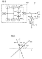
- FIG. 3 shows an exemplary structure of a transceiver SE a base station SLG, with an IQ modulator MOD and a mixer MIX3 to form the carrier phase signal PS.
- the IQ modulator MOD has in the example of the figure two so-called "look-up tables" ILT, QLT, which contain digital samples for the necessary signal waveform for the modulation. Time controlled via a clock generator CLK, the samples are each supplied to a digital / analog converter DAC1, DAC2 and converted into an analog signal. The analog signals are then modulated in quadrature by means of two by 90 ° shifted RF carrier frequencies OSZ, PH, PHS through the two mixers MIX1, MIX2 the carrier.
- the two mixed signals are combined into an RF carrier signal TS and fed to an antenna SEA for transmission.
- An RF carrier signal RS backscattered by a mobile object DT1-DT3 is then added together with the transmitting RF carrier signal TS mixed with the mixer MIX3 to a carrier phase signal PS.
- a downstream filter FIL such as a low pass, disturbing frequency components are removed.
- the respective phase PH1, PH2 is then supplied to an electronic signal processing SV and determined by difference formation dPH the associated distance by calculation.
- FIG. 4 shows an exemplary constellation diagram I, Q for the graphical representation of exemplary measurement points MP1, MP2 for the distance determination.
- Two measurement points MP1, MP2 for the respective phase PH1, PH2 of in each case two HF carrier corner frequencies fo + df, fo-df are entered.
- the drawn lines represent an example of the averaging result for the phases PH1, PH2.
Landscapes
- Engineering & Computer Science (AREA)
- Radar, Positioning & Navigation (AREA)
- Remote Sensing (AREA)
- Computer Networks & Wireless Communication (AREA)
- Physics & Mathematics (AREA)
- General Physics & Mathematics (AREA)
- Radar Systems Or Details Thereof (AREA)
- Mobile Radio Communication Systems (AREA)
- Control And Other Processes For Unpacking Of Materials (AREA)
Description
- Die Erfindung betrifft ein Verfahren zur Abstandsbestimmung zwischen einem Schreib-/Lesegerät und zumindest einem mobilen Datenspeicher in einem Identifikationssystem mit mindestens einem mobilen Datenspeicher zur Erfassung von gegenstandsbezogenen Zustands- und/oder Prozessdaten wie z.B. in einem Versand-, Transport- und/ oder Fertigungssystem.
- Als Stand der Technik sind Verfahren zur Abstandsbestimmung bekannt, wie z.B. das RADAR. Von einer stationären Basisstation werden Radarwellen ausgesandt und von einem mobilen oder beweglichen Objekt, wie z.B. Fahrzeuge, Personen, Transponder etc., zurückgestreut. Zur Abstandsbestimmung werden dabei vorzugsweise bekannte Modulationsverfahren auf Basis von kontinuierlichen sinusförmigen Signalen (Continuous Wave), wie z.B. das FMCW-, LFM- oder FSK-Modulationsverfahren, verwendet. Eine gängige Möglichkeit zur Durchführung der o.g. Modulationsverfahren ist die Verwendung eines IQ-Modulators (Quadratur-Amplitudenmodulator). Durch Trägerphasenmessung für verschiedene Frequenzen ist dann eine Abstandsbestimmung und ggf. auch eine Geschwindigkeitsbestimmung eines in der Nähe befindlichen mobilen Objekts möglich.
- Aus der
EP 1 107 162 A1 ist ein Verfahren zur Datenübertragung mit Laufzeitmessung zur Selektion von Empfangsdaten bekannt. In einem Schreib-Lese-Gerät wird die Phase eines im mobilen Datenspeicher mit Hilfsträger modulierten und rückgesendeten Datensignals am Anfang und am Ende eines Zeitschlitzes des gerasterten Datenstroms des Schreib-Lese-Geräts festgestellt. Eine ermittelte Phasendifferenz in Bezug zum ausgesendeten Datensignal des Schreib-Lese-Geräts ist proportional zum Abstand zwischen dem Schreib-Lese-Gerät und dem mobilen Datenspeicher, dessen rückgesendetes Datensignal empfangen wurde. - Aus der
EP 0 933 648 A1 ist ein Doppler-Radar-Verkehrsmesssystem zur Verkehrsmessung und Verkehrsüberwachung auf Verkehrsstraßen, wie Autobahnen, Schienenwegen, Wasserstraßen, Schleusen oder dergleichen bekannt. Das System weist ein Radar-Sende/Empfangsgerät mit Mitteln zum Aussenden eines FMCW-Radars mit zwei benachbarten Frequenzen auf. Die Phasendifferenz der Differenzfrequenz dient zur Abstandsbestimmung, welche ihrerseits einer bestimmten Fahrspur zugeordnet werden kann, in der ein gemessener Verkehrteilnehmer, wie z.B. ein Fahrzeug, ein Schiff oder ein Zug, erfasst worden ist. Es kann gleichzeitig auch die Geschwindigkeit des Verkehrsteilnehmers sowie die Fahrrichtung auf Basis des Vorzeichens der Dopplerverschiebung ermittelt werden. - Weiterhin sind Identifikationssysteme bekannt, die eine oder mehrere stationäre Basisstationen - die so genannten Schreib/Lesegeräte - enthalten, welche Daten mit mobilen Datenspeichern als mobile Objekte über eine in der Regel auf Funk basierenden Datenübertragungsstrecke berührungslos austauschen. Derartige Systeme werden in technischen Einrichtungen eingesetzt, in welchen eine Vielzahl von Gegenständen bzw. Güter möglichst schnell und frei bewegt werden müssen. Die Gegenstände können dabei unterschiedlichster Art sein, z.B. Pakete in einer Versandeinrichtung, Montageteile in einer Fertigungsanlage, Gepäckstücke in einem Transportsystem und vieles mehr.
- Ein Beispiel für ein derartiges Identifikationssystem ist im ISO-18000-4-MOD3-Standard mit dem Titel "Radio-frequency Identification Standard for Item Management - Air Interface" beschrieben. In der Norm ist vorgesehen, dass durch das Schreib-/Lesegerät eine Abfrage auf Vorhandensein eines mobilen Datenspeichers im Erfassungsbereich erfolgt. Dazu sendet dieses ein unmoduliertes HF-Trägersignal mit einer festgelegten HF-Trägerfrequenz, wie z.B. von 2,45 GHz, aus. Dieses Trägersignal kann passiv von einem in der Nähe befindlichen mobilen Datenspeicher z.B. durch sog. "Back-Scattering" zum Schreib-/Lesegerät mit Daten moduliert zurückgestreut werden und dann dort weiterverarbeitet werden.
- Beim Betrieb von zwei oder mehreren, insbesondere von nahe zueinander angeordneten Basisstationen und mobilen Datenspeichern, wie z.B. bei benachbarten Fertigungsstraßen, ist darauf zu achten, dass es nicht zu unerwünschten Wechselwirkungen wie z.B. durch Überreichweiten zwischen den einzelnen Basisstationen und den jeweiligen mobilen Datenspeichern kommt. Es ist daher notwendig, dass der Erfassungsbereich der jeweiligen Basisstation eingeschränkt wird. Diese kann z.B. auf Basis einer Abstandsbestimmung zwischen der Basisstation und dem jeweiligen mobilen Datenspeicher erfolgen.
- Bei der herkömmlichen Erzeugung der Frequenzen für die Abstandsbestimmung können starke Messungenauigkeiten auftreten. Ursache dafür ist, dass die Anfangsphasen der in der Basisstation erzeugten Frequenzen nicht zusammenhängen, d.h. nicht miteinander korrelieren. Dies ist z.B. dann der Fall, wenn die jeweiligen Frequenzen von verschiedenen Oszillatoren stammen oder die Frequenzerzeugung mittels eines PLL (Phase Locked Loop) geschieht. Um die gewünschte Korrelation zu erreichen, müssen daher die Signalphasen bei jeder Frequenz mit aufwendigen Schaltungen zuerst im Senderteil gemessen.
- Der Erfindung liegt die Aufgabe zugrunde, die Messgenauigkeit einer Abstandsbestimmung zwischen einem Schreib-/Lesegerät und mindestens einem mobilen Datenspeicher zu erhöhen. Ferner sollen ein Schreib-/Lesegerät und ein Identifikationssystem angeboten werden.
- Die Aufgabe der Erfindung wird dadurch gelöst, dass für das zu sendende HF-Trägersignals eine HF-Trägerfrequenz und eine Offsetfrequenz für eine IQ-Modulation vorgegeben werden. Mittels IQ-Modulation wird die HF-Trägerfrequenz zeitsequentiell so um die Offsetfrequenz erhöht und erniedrigt, dass die in einem modulierten HF-Trägersignal resultierenden HF-Trägereckfrequenzen eine gleiche Phase aufweisen. Es wird dann für beide HF-Trägereckfrequenzen die zugehörige Trägerphase zur Bildung der Phasendifferenz zeitsequentiell ermittelt.
- Vorteilhafte Verfahrensvarianten werden in den Unteransprüchen 2 bis 6 beschrieben.
- Für das Schreib-/Lesegerät wird die Aufgabe der Erfindung durch die Merkmale des Patentanspruchs 7 und für das Identifikationssystem durch die Merkmale des Patentanspruchs 8 gelöst.
- Hierdurch wird erreicht, dass die Phase der beiden im HF-Trägersignal IQ-modulierten HF-Trägereckfrequenzen im Schreib-/Lesegerät gleich ist. Dadurch entstehen in vorteilhafter Weise nicht die sonst üblichen Phasensprünge bei einem Frequenzwechsel. Eine zusätzliche Messung am Sender im Schreib-/Lesegerät sowie die dafür benötigte Messzeit können dadurch vorteilhaft entfallen.
- Nach einer vorteilhaften Verfahrensvariante wird zwischen zwei Abstandsbestimmungen die HF-Trägerfrequenz und/oder die Offsetfrequenz geändert. Dadurch kann bei Vorhandensein von Störungen in einem Frequenzband auf ein anderes Frequenzband ausgewichen werden. Die Frequenzbänder können dabei verschiedenen Frequenzkanälen entsprechen.
- Nach einer weiteren vorteilhaften Verfahrensvariante können mehrere Abstandsbestimmungen und dann eine Mittelung über alle einzelnen Abstanosbestimmungen erfolgen.
- Dadurch ist eine Erhöhung der Messgenauigkeit möglich. Die Abstandsbestimmung kann somit sehr genau durchgeführt werden.
- Bei einer Verfahrensvariante ist die Basisstation ein Schreib-/Lesegerät und das mobile Objekt ein mobiler Datenspeicher. Durch frequenztechnische Abstimmung aufeinander ist vorteilhaft ein gutes Rückstreuverhalten für die Abstandsbestimmung, wie z.B. mittels des Backscatter-Verfahrens, gegeben.
- Nach einer vorteilhaften Verfahrensvariante erfolgt die Abstandsmessung zwischen Schreib-/Lesegerät und mobilem Datenspeicher in einem Übertragungskanal, insbesondere in einem Übertragungskanal mit vier Kanälen, wobei auf den einzelnen Kanälen Signale unterschiedlicher Frequenzen ausgesendet werden.
- Vorteilhafterweise ist das erfindungsgemäße Verfahren an das Übertragungsverfahren ISO-18000-4-MOD3-Standard angelehnt und übernimmt unter Modifikation zumindest einen dort vorhandenen Kanal.
- Unter Anpassung des ISO-18000-4-MOD3-Standard kann der Übertragungskanal dem Notification-Channel des ISO-18000-4-MOD3-Standards entsprechen. U.U. kann dazu auch zumindest ein Kanal des Communication-Channel entsprechend dem o.g. Standard herangezogen werden.
- Bei der jeweiligen Zuordnung können die Kanäle des Übertragungskanals R2-Kanäle im Notification-Channel des ISO-18000-4-MOD3-Standards sein.
- Das Verfahren kann vorteilhaft in einem Identifikationssystem mit einer Basisstation und mit mindestens einem an Transportgegenständen angebrachten mobilen Datenspeicher zur Erfassung von gegenstandsbezogenen Zustands- und/oder Prozessdaten verwendet werden.
- Das Verfahren kann erfindungsgemäß mit einer Basisstation mit zumindest einem Sendeempfänger und einer elektronischen Signalverarbeitung durchgeführt werden, wobei der Sendeempfänger zumindest einen digitalen IQ-Modulator, eine Sende- und Empfangsantenne zur Abstrahlung und zum Empfang der HF-Trägersignale, und einen Mischer für die HF-Trägersignale zur Bildung des Trägerphasensignals für die Abstandsbestimmung zwischen Basisstation und mobilem Objekt durch die elektronische Signalverarbeitung aufweist.
- Ein wesentlicher Vorteil ist es, dass durch Nutzung schon bestehender Schaltungskomponenten, wie PLL zur Veränderung der HF-Trägerfrequenz und IQ-Modulator zur Datenmodulation eine Trägerphasenmessung möglich ist. Es ist somit eine Abstandsmessung mit ausreichender hoher Genauigkeit ohne zusätzlichen Aufwand von elektronischen Schaltungskomponenten möglich.
- Die Erfindung wird anhand der nachfolgenden Figuren näher erläutert. Dabei zeigt
- FIG 1 :
- ein Beispiel für den Einsatz einer Basisstation als Schreib-/Lesegerät und mehrere mobile Datenspeicher als beispielhaft mobile Objekte,
- FIG 2 :
- eine beispielhafte Datenstruktur eines Übertra- gungskanals,
- FIG 3 :
- einen beispielhaften Aufbau eines Sendeempfängers einer Basisstation, mit einem IQ-Modulator und ei- nem Mischer zur Bildung des Trägerphasensignals, und
- FIG 4 :
- ein beispielhaftes Konstellationsdiagramm zur gra- fischen Darstellung von beispielhaften Messpunkten der jeweiligen Phase von je zwei HF-Trägereckfre- quenzen.
-
FIG 1 zeigt ein Beispiel für den Einsatz einer Basisstation SLG als Schreib-/Lesegerät und mehrere mobile Datenspeicher DT1-DT3. Zusammen mit einer zwischen den Datenspeichern DT1-DT3 und der Basisstation SLG liegenden Luftschnittstelle LS bilden diese ein Identifikationssystem IS. Mögliche unterschiedliche Bewegungsrichtungen BR1-BR3 der mobilen Datenspeicher DT1-DT3 sind beispielhaft in der Figur eingetragen. Zur Datenkommunikation verfügen die Datenspeicher DT1-DT3 sowie die Basisstation SLG über je eine Antenne ANT,SEA. In der Basisstation SLG ist in punktstrichlierter Darstellung ein Senderempfänger SE zu sehen, welcher der Durchführung des erfindungsgemäßen Verfahrens dient. -
FIG 2 zeigt eine beispielhafte Datenstruktur eines Übertragungskanals N-CH für die Kommunikation zwischen mobilem Datenspeicher DT1-DT3 und Schreib-/Lesegerät SLG. Die Datenstruktur des Übertragungskanals N-CH ist dabei dem Notification-Channel im ISO-18000-4-MOD3-Standard angelehnt. Zur Durchführung einer oder mehrerer Abstandsmessungen sind nun ein oder mehrere der Kanäle K1 bis K4 vorgesehen. Bei Anlehnung an den ISO-18000-4-MOD3-Standard entsprechen diese Kanäle K1 bis K4 den R2-Kanälen R2 im Notification-Channel des ISO-18000-4-MOD3-Standards. In der vorliegenden Figur ist eine beispielhafte Unterstruktur eines R2-Kanals R2 dargestellt, welcher fünf Zeitblöcke aufweist. Im ersten Block KONF erfolgt die Programmierung des PLL für die Einstellung der HF-Trägerfrequenz fo. Im folgenden Block NPM wird ein negativer Frequenzsprung auf die untere HF-Trägereckfrequenz fo-df durch den IQ-Modulator MOD eingestellt. Anschließend wird im Trägerphasensignal PS die erste Trägerphase PH1 und die entsprechenden Messdaten DAT1 z.B. durch einen digitalen Signalprozessor (DSP) weiterverarbeitet. Nachfolgend erfolgt der positive Frequenzsprung im Zeitblock PPM auf die Frequenz fo+df, zusammen mit den ersten Messdaten DAT1 wird mit den zweiten Messdaten DAT2 die Trägerphasendifferenz dPH gebildet. Für den o.g. Standard ist somit eine Abstandsmessung in einem R2-Kanal in ca. 0.5 ms möglich. -
FIG 3 zeigt einen beispielhaften Aufbau eines Sendeempfängers SE einer Basisstation SLG, mit einem IQ-Modulator MOD und einem Mischer MIX3 zur Bildung des Trägerphasensignals PS. Der IQ-Modulator MOD weist im Beispiel der Figur zwei so genannte "Look-up Tables" ILT,QLT auf, welche digitale Abtastwerte für die notwendige Signalwellenform für die Modulation enthalten. Zeitlich über einen Taktgenerator CLK gesteuert werden die Abtastwerte je einem Digital/Analog-Umsetzer DAC1, DAC2 zugeführt und in je ein analoges Signal umgewandelt. Die analogen Signale werden nun in Quadratur mittels zweier um 90° verschobenen HF-Trägerfrequenzen OSZ,fo,PHS durch die beiden Mischer MIX1, MIX2 dem Träger aufmoduliert. Mit einem HF-Combiner HFC werden die beiden gemischten Signale zu einem HF-Trägersignal TS zusammengefasst und einer Antenne SEA zum Senden zugeführt. Ein von einem mobilen Objekt DT1-DT3 zurückgestreutes HF-Trägersignal RS wird dann zusammen mit dem zu sendenden HF-Trägersignal TS mit dem Mischer MIX3 zu einem Trägerphasensignal PS vermischt. Über einen nachgeschalteten Filter FIL, wie z.B. einen Tiefpass, werden störende Frequenzanteile entfernt. Die jeweilige Phase PH1,PH2 wird dann einer elektronischen Signalverarbeitung SV zugeführt und nach Differenzbildung dPH der zugehörige Abstand rechnerisch bestimmt. -
FIG 4 zeigt ein beispielhaftes Konstellationsdiagramm I,Q zur grafischen Darstellung von beispielhaften Messpunkten MP1,MP2 für die Abstandsbestimmung. Es werden je zwei Messpunkte MP1, MP2 für die jeweilige Phase PH1,PH2 von je zwei HF-Trägereckfrequenzen fo+df,fo-df eingetragen. Die eingezeichneten Geraden stellen dabei exemplarisch das Mittelungsergebnis für die Phasen PH1, PH2 dar.
Claims (8)
- Verfahren zur Abstandsbestimmung zwischen einem Schreib-/Lesegerät (SLG) und einem mobilen Datenspeicher (DT1-DT3) eines Identifikationssystems (IS), wobei im Schreib-/Lesegerät (SLG)a) ein gesendetes HF-Trägersignal (TS) und ein vom mobilen Datenspeicher (DT1-DT3) zurückgestreutes HF-Trägersignal (RS) zugleich miteinander gemischt (MIX3) werden, wobei ein Trägerphasensignal (PS) entsteht, undb) aus der Phasendifferenz der Abstand zwischen Schreib-/Lesegerät (SLG) und dem jeweiligen mobilen Datenspeicher (DT1-DT3) bestimmt wird,
dadurch gekennzeichnet, dassc) für das zu sendende HF-Trägersignal (TS) eine HF-Trägerfrequenz (fo) und eine Offsetfrequenz (df) für eine IQ-Modulation (MOD) vorgegeben werden,d) mittels IQ-Modulation die HF-Trägerfrequenz (fo) zeitsequentiell so um die Offsetfrequenz (df) erhöht und erniedrigt wird, dass die in einem modulierten HF-Trägersignal (TS) resultierenden HF-Trägereckfrequenzen (fo+df, fo-df) eine gleiche Phase aufweisen, und danne) für beide HF-Trägereckfrequenzen (fo+df, fo-df) die zugehörige Trägerphase (PH1, PH2) aus dem Trägerphasensignal (PS) zur Bildung der Phasendifferenz (dPH) zeitsequentiell ermittelt wird. - Verfahren nach Anspruch 1, wobei zwischen zwei Abstandsbestimmungen die HF-Trägerfrequenz (fo) und/oder die Offsetfrequenz (df) geändert werden.
- Verfahren nach Anspruch 1 oder 2, wobei mehrere Abstandsbestimmungen erfolgen und dann eine Mittelung erfolgt.
- Verfahren nach einem der vorangegangenen Ansprüche, wobei die Abstandsbestimmung zwischen Schreib-/Lesegerät (SLG) und mobilem Datenspeicher (DT1-DT3) in einem Übertragungskanal (N-CH) für die Kommunikation zwischen mobilem Datenspeicher (DT1-DT3) und Schreib-/Lesegerät (SLG) erfolgt.
- Verfahren nach Anspruch 4, wobei die Abstandsbestimmung in einem oder mehreren Zeitabschnitten (K1-K4) des Übertragungskanals (N-CH) erfolgt.
- Verfahren nach Anspruch 4 oder 5, wobei die Datenübertragung zwischen Schreib-/Lesegerät (SLG) und mobilem Datenspeicher (DT1-DT3) nach dem ISO-18000-4-MOD3-Standard erfolgt.
- Schreib-/Lesegerät mit einem Sendeempfänger (SE), wobei der Sendeempfänger (SE) zumindest einen digitalen IQ-Modulator (MOD), eine Sende- und Empfangsantenne (SEA) zur Abstrahlung und zum Empfang der HF-Trägersignale (TS, RS) und einen Mischer (MIX3) für die HF-Trägersignale (TS, RS) zur Bildung des Trägerphasensignals (PS) für die Abstandsbestimmung zwischen Schreib-/Lesegerät (SLG) und mobilem Datenspeicher (DT1-DT3) aufweist, wobei das Schreib-/Lesegerät weiterhin eine elektronische Signalverarbeitung (SV) zumindest zur Weiterverarbeitung des Trägerphasensignals (PS) aufweist,
dadurch gekennzeichnet, dass
der Sendeempfänger (SE) und die elektronische Signalverarbeitung (SV) derart ausgebildet sind, dass sie im Betrieb des Schreib-/Lesegeräts ein Verfahren nach einem der vorangegangenen Ansprüche ausführen. - Identifikationssystem mit zumindest einem Schreib-/Lesegerät (SLG) nach Anspruch 7 und mindestens einem mobilen Datenspeicher (DT1-DT3) zur Erfassung von gegenstandsbezogenen Zustands- und/oder Prozessdaten.
Applications Claiming Priority (3)
| Application Number | Priority Date | Filing Date | Title |
|---|---|---|---|
| DE10261098 | 2002-12-20 | ||
| DE10261098A DE10261098A1 (de) | 2002-12-20 | 2002-12-20 | Verfahren zur Abstandsbestimmung zwischen einer Basisstation und einem mobilen Objekt sowie Basisstation und Identifikationssystem für ein derartiges Verfahren |
| PCT/EP2003/014014 WO2004059340A1 (de) | 2002-12-20 | 2003-12-10 | Verfahren zur abstandsbestimmung zwischen einer basisstation und einem mobilen objekt, sowie basisstation und identifikationssystem für ein derartiges verfahren |
Publications (2)
| Publication Number | Publication Date |
|---|---|
| EP1466189A1 EP1466189A1 (de) | 2004-10-13 |
| EP1466189B1 true EP1466189B1 (de) | 2009-03-11 |
Family
ID=32519390
Family Applications (1)
| Application Number | Title | Priority Date | Filing Date |
|---|---|---|---|
| EP03813887A Expired - Lifetime EP1466189B1 (de) | 2002-12-20 | 2003-12-10 | Verfahren zur abstandsbestimmung zwischen einer basisstation und einem mobilen objekt, sowie basisstation und identifikationssystem für ein derartiges verfahren |
Country Status (9)
| Country | Link |
|---|---|
| US (1) | US7205931B2 (de) |
| EP (1) | EP1466189B1 (de) |
| JP (1) | JP2006510910A (de) |
| CN (1) | CN100350266C (de) |
| AT (1) | ATE425469T1 (de) |
| AU (1) | AU2003296635A1 (de) |
| CA (1) | CA2479225C (de) |
| DE (2) | DE10261098A1 (de) |
| WO (1) | WO2004059340A1 (de) |
Families Citing this family (46)
| Publication number | Priority date | Publication date | Assignee | Title |
|---|---|---|---|---|
| EP1554683B1 (de) * | 2002-10-22 | 2012-08-29 | Siemens Aktiengesellschaft | Verfahren zur überprüfung der qualität der datenübertragung zwischen einem schreib-/lese-gerät (slg) und mindestens einem mobilen datenspeicher (mds) sowie schreib-/lese-gerät (slg) und mobiler datenspeicher (mds) zur anwendung des verfahrens |
| GB0426446D0 (en) * | 2004-12-02 | 2005-01-05 | Koninkl Philips Electronics Nv | Measuring the distance between devices |
| DE102005009579B4 (de) | 2005-02-28 | 2010-04-22 | ASTRA Gesellschaft für Asset Management mbH & Co. KG | Verfahren zur Lokalisierung eines Detektierplättchens |
| JP5440893B2 (ja) * | 2005-03-09 | 2014-03-12 | オムロン株式会社 | 情報処理装置、情報処理方法、反射体、および通信システム |
| KR101038617B1 (ko) * | 2005-03-09 | 2011-06-03 | 오므론 가부시키가이샤 | 거리 측정 장치, 거리 측정 방법, 반사체 및 통신 시스템 |
| US7405662B2 (en) * | 2005-06-14 | 2008-07-29 | Datalogic Mobile, Inc. | Wireless tag ranging |
| NL1029589C2 (nl) * | 2005-07-22 | 2007-01-29 | Nedap Nv | Methode voor het meten van afstand tussen leeseenheid en label in een RFID-systeem door middel van fasemetingen. |
| EP1764623A1 (de) | 2005-09-15 | 2007-03-21 | Siemens Aktiengesellschaft | Verfahren und Vorrichtung zur Abstandsbestimmung zwischen einem RFID Schreib-/Lesegerät und einem mobilen RFID-Datenspeicher |
| EP1764627A1 (de) | 2005-09-15 | 2007-03-21 | Siemens Aktiengesellschaft | Verfahren und Vorrichtung zur Abstandsbestimmung zwischen einem RFID Schreib-/Lesegerät und einem mobilen RFID-Datenspeicher |
| WO2007045518A1 (de) * | 2005-10-18 | 2007-04-26 | Siemens Aktiengesellschaft | Verfahren und vorrichtung zur einreihung eines mobilen datenspeichers in die protokollstruktur für die kommunikation mit einem schreib-/lesegerät |
| US8107446B2 (en) * | 2005-11-07 | 2012-01-31 | Radiofy Llc | Wireless RFID networking systems and methods |
| JP4315151B2 (ja) * | 2005-12-20 | 2009-08-19 | ソニー株式会社 | 無線通信装置 |
| JP4270299B2 (ja) * | 2006-03-28 | 2009-05-27 | オムロン株式会社 | Rfidタグ距離測定装置およびrfidタグ距離測定システム |
| US20080143584A1 (en) * | 2006-12-18 | 2008-06-19 | Radiofy Llc, A California Limited Liability Company | Method and system for determining the distance between an RFID reader and an RFID tag using phase |
| US8314736B2 (en) | 2008-03-31 | 2012-11-20 | Golba Llc | Determining the position of a mobile device using the characteristics of received signals and a reference database |
| US8344949B2 (en) | 2008-03-31 | 2013-01-01 | Golba Llc | Wireless positioning approach using time-delay of signals with a known transmission pattern |
| US8294554B2 (en) | 2006-12-18 | 2012-10-23 | Radiofy Llc | RFID location systems and methods |
| US20090002165A1 (en) * | 2007-06-28 | 2009-01-01 | Micron Technology, Inc. | Method and system of determining a location characteristic of a rfid tag |
| US9829560B2 (en) | 2008-03-31 | 2017-11-28 | Golba Llc | Determining the position of a mobile device using the characteristics of received signals and a reference database |
| US7800541B2 (en) | 2008-03-31 | 2010-09-21 | Golba Llc | Methods and systems for determining the location of an electronic device |
| US8260319B2 (en) * | 2008-06-10 | 2012-09-04 | Rosemount Tank Radar Ab | Wireless transceiver |
| US20110109440A1 (en) * | 2008-07-02 | 2011-05-12 | Nxp B.V. | System for reading information transmitted from a transponder |
| US8279112B2 (en) * | 2008-11-03 | 2012-10-02 | Trimble Navigation Limited | Methods and apparatuses for RFID tag range determination |
| DE102009008174A1 (de) * | 2009-02-10 | 2010-08-19 | Siemens Aktiengesellschaft | Verfahren und System zur Bestimmung der Entfernung, der Geschwindigkeit und/oder der Bewegungsrichtung eines RFID-Transponders |
| US7801512B1 (en) * | 2009-03-05 | 2010-09-21 | Makor Issues And Rights Ltd. | Traffic speed enforcement based on wireless phone network |
| DE102009045141A1 (de) * | 2009-09-30 | 2011-03-31 | Robert Bosch Gmbh | Radarsensor mit IQ-Empfänger |
| US8823577B2 (en) * | 2009-12-23 | 2014-09-02 | Itrack, Llc | Distance separation tracking system |
| US20110221633A1 (en) * | 2010-03-11 | 2011-09-15 | Benjamin Bela Schramm | Methods and systems for determining the distance between two objects using wirelessly transmitted pulses |
| US20130241701A1 (en) * | 2010-09-13 | 2013-09-19 | Trident Rfid Pty Ltd | System and method for updating parameters and firmware on rfid readers |
| CA2812627C (en) * | 2010-09-28 | 2019-10-29 | Siemens Aktiengesellschaft | Power oscillation damping by a converter-based power generation device |
| US8774837B2 (en) | 2011-04-30 | 2014-07-08 | John Anthony Wright | Methods, systems and apparatuses of emergency vehicle locating and the disruption thereof |
| US8723720B2 (en) * | 2011-05-03 | 2014-05-13 | Harris Corporation | Wireless location detection and/or tracking device and associated methods |
| US10082568B1 (en) * | 2013-01-22 | 2018-09-25 | Hoyt Mac Layson, JR. | Detailed description |
| US9766322B2 (en) | 2013-03-14 | 2017-09-19 | Ensco, Inc. | Geolocation with radio-frequency ranging |
| US9709672B2 (en) * | 2013-08-16 | 2017-07-18 | Drnc Holdings, Inc. | Method and system for identifying and finding a range of an object |
| US9958533B2 (en) | 2013-09-06 | 2018-05-01 | Drnc Holdings, Inc. | Method and system for locating wireless devices within a local region |
| US9392533B1 (en) | 2013-12-03 | 2016-07-12 | Sprint Spectrum L.P. | Methods and systems for determining a position of a user equipment device in a multi-band wireless communication system |
| US9829574B2 (en) | 2014-06-02 | 2017-11-28 | Ensco, Inc. | Carrier phase distance and velocity measurements |
| US9612325B2 (en) * | 2014-06-02 | 2017-04-04 | Ensco, Inc. | Unwrapping and prediction of distance and velocity measurements using carrier signals |
| CN107111772B (zh) | 2014-09-22 | 2020-12-25 | Drnc控股公司 | 用于使用德尔塔-西格玛调制的无线设备的传输装置 |
| FR3044100B1 (fr) * | 2015-10-19 | 2018-01-05 | Valeo Comfort And Driving Assistance | Procede d'estimation d'une distance et unite electronique pour vehicule |
| GB2545678B (en) * | 2015-12-21 | 2020-06-03 | Canon Kk | Method and apparatus for transmitting a continuous radar wave |
| WO2018059782A1 (de) * | 2016-09-30 | 2018-04-05 | Fraunhofer-Gesellschaft zur Förderung der angewandten Forschung e.V. | Telegram splitting basierte lokalisierung |
| DE102018118192A1 (de) * | 2018-07-27 | 2020-02-20 | Hochschule Trier University of Applied Sciences | Radarsystem |
| US12039397B2 (en) * | 2022-09-27 | 2024-07-16 | Cypress Semiconductor Corporation | Systems, methods, and devices for wireless communication device-based detection of radio frequency identification devices |
| US12248836B2 (en) * | 2022-09-27 | 2025-03-11 | Cypress Semiconductor Corporation | Systems, methods, and devices for wireless detection of radio frequency identification devices |
Family Cites Families (13)
| Publication number | Priority date | Publication date | Assignee | Title |
|---|---|---|---|---|
| US4283726A (en) * | 1978-09-05 | 1981-08-11 | Lewis C. Spence | Dual frequency distance measuring system |
| SE456867B (sv) * | 1985-12-12 | 1988-11-07 | Stiftelsen Inst Mikrovags | Saett att uppmaeta avstaand och/eller hastighet mellan tvaa foeremaal |
| US4983976A (en) * | 1988-06-17 | 1991-01-08 | Omron Tateisi Electronics Co. | Signal transmission system and method |
| FR2681433B1 (fr) * | 1991-09-18 | 1993-10-29 | Jean Guena | Systeme de mesure de distance entre deux stations mobiles l'une par rapport a l'autre. |
| US5298904A (en) * | 1992-08-04 | 1994-03-29 | Olich Kirk J | Distance measuring system |
| US6812824B1 (en) * | 1996-10-17 | 2004-11-02 | Rf Technologies, Inc. | Method and apparatus combining a tracking system and a wireless communication system |
| NL1008087C2 (nl) * | 1998-01-22 | 1999-07-26 | Chl Netherlands Bv | Dopplerradar-verkeersmeetsysteem. |
| EP1107162A1 (de) * | 1999-12-09 | 2001-06-13 | Siemens Aktiengesellschaft | Verfahren zur Datenübertragung mit Laufzeitmessung zur Selektion von Empfangsdaten |
| EP1236158B1 (de) * | 1999-12-09 | 2011-05-18 | Siemens Aktiengesellschaft | Verfahren zur datenübertragung zwischen mindestens einem schreib-lese-gerät (slg) und mindestens einem mobilen datenspeicher (mds) in einem identifikationssystem mit laufzeitmessung zur selektion von empfangsdaten |
| US6868073B1 (en) * | 2000-06-06 | 2005-03-15 | Battelle Memorial Institute K1-53 | Distance/ranging by determination of RF phase delta |
| EP1295148A2 (de) * | 2000-06-27 | 2003-03-26 | Siemens Aktiengesellschaft | Zugangskontrolle und fahrberechtigung mit abstandsmessung für ein kraftfahrzeug |
| US7024331B2 (en) * | 2000-11-15 | 2006-04-04 | Scientific Generics Limited | Tag tracking |
| US6859761B2 (en) * | 2001-01-16 | 2005-02-22 | Bluesoft Ltd. | Accurate distance measurement using RF techniques |
-
2002
- 2002-12-20 DE DE10261098A patent/DE10261098A1/de not_active Withdrawn
-
2003
- 2003-12-10 CN CNB2003801003454A patent/CN100350266C/zh not_active Expired - Fee Related
- 2003-12-10 DE DE50311273T patent/DE50311273D1/de not_active Expired - Lifetime
- 2003-12-10 AU AU2003296635A patent/AU2003296635A1/en not_active Abandoned
- 2003-12-10 CA CA2479225A patent/CA2479225C/en not_active Expired - Fee Related
- 2003-12-10 AT AT03813887T patent/ATE425469T1/de not_active IP Right Cessation
- 2003-12-10 WO PCT/EP2003/014014 patent/WO2004059340A1/de not_active Ceased
- 2003-12-10 JP JP2004562721A patent/JP2006510910A/ja active Pending
- 2003-12-10 EP EP03813887A patent/EP1466189B1/de not_active Expired - Lifetime
-
2004
- 2004-09-15 US US10/940,657 patent/US7205931B2/en not_active Expired - Fee Related
Also Published As
| Publication number | Publication date |
|---|---|
| CA2479225C (en) | 2013-04-09 |
| CN100350266C (zh) | 2007-11-21 |
| ATE425469T1 (de) | 2009-03-15 |
| CA2479225A1 (en) | 2004-07-15 |
| DE50311273D1 (de) | 2009-04-23 |
| WO2004059340A1 (de) | 2004-07-15 |
| AU2003296635A1 (en) | 2004-07-22 |
| EP1466189A1 (de) | 2004-10-13 |
| DE10261098A1 (de) | 2004-07-15 |
| US7205931B2 (en) | 2007-04-17 |
| CN1692287A (zh) | 2005-11-02 |
| JP2006510910A (ja) | 2006-03-30 |
| US20050099333A1 (en) | 2005-05-12 |
Similar Documents
| Publication | Publication Date | Title |
|---|---|---|
| EP1466189A1 (de) | Verfahren zur abstandsbestimmung zwischen einer basisstation und einem mobilen objekt, sowie basisstation und identifikationssystem für ein derartiges verfahren | |
| EP0727051B1 (de) | Radargerät und verfahren zu seinem betrieb | |
| EP2845026B1 (de) | Verfahren und anordnung zur relativen lageerkennung von stationen mittels funkortung | |
| DE69020203T2 (de) | Verfahren und Gerät zur Hilfe des Landfahrzeugverkehrs. | |
| DE10345565B4 (de) | Impulsradarvorrichtung | |
| DE10104022A1 (de) | Radareinrichtung und Verfahren zum Codieren einer Radareinrichtung | |
| DE10100414A1 (de) | Radareinrichtung und Verfahren zum Unterdrücken von Störungen einer Radareinrichtung | |
| DE102009045141A1 (de) | Radarsensor mit IQ-Empfänger | |
| DE2514868A1 (de) | Rueckstrahlortungsgeraet zur gleichzeitigen messung von entfernung und relativgeschwindigkeit | |
| EP1309885A1 (de) | Verfahren zur pulsbreitenmodulation eines radarsystems | |
| EP0519361B1 (de) | Dauerstrich-Radargerät, zusätzlich als Sender für die Informationsübertragung verwendbar | |
| DE19703237C1 (de) | Radar-Abstandsmesser | |
| DE102009027495A1 (de) | Heterodyn-Sende-/Empfangssysteme und Verfahren | |
| EP1556259B1 (de) | Verfahren zur ermittlung des abstands zwischen einer ersten und zweiten sende-empfangs-station | |
| DE102004006446B4 (de) | Verfahren und Schaltungsanordnung zur drahtlosen Datenübertragung | |
| EP1549971A1 (de) | Verfahren zur ermittlung des abstands zwischen zwei sende-empfangs-stationen | |
| EP1537436A1 (de) | Vorrichtung und verfahren zur einseitenband-modulation eines radarsignals | |
| DE10226575A1 (de) | Verfahren und Vorrichtung zum Erzeugen von HF-Signalen zum Bestimmen eines Abstandes und/oder einer Geschwindigkeit eines Objektes | |
| DE102022116281A1 (de) | Radarvorrichtung und verfahren | |
| DE2433203B2 (de) | Frequenzumtast-Doppler-Radarsystem zur Entfernungs- und Geschwindigkeitsmessung | |
| EP1764627A1 (de) | Verfahren und Vorrichtung zur Abstandsbestimmung zwischen einem RFID Schreib-/Lesegerät und einem mobilen RFID-Datenspeicher | |
| DE3917794C2 (de) | Verfahren zur Bestimmung des Zündpunktes eines Flugkörpers sowie Schaltungsanordnung zur Durchführung des Verfahrens | |
| DE102005020246B4 (de) | Verfahren zur Bestimmung und Einstellung der Zwischenfrequenz bei Frequenz-Puls-Radarsystemen und Frequenz-Puls-Radarsystem | |
| DE10261097A1 (de) | Verfahren zur Freigabe einer Datenübertragung zwischen einem Schreib-/Lesegerät und mindestens einem mobilen Datenspeicher, sowie Schreib-/Lesegerät und Identifikationssystem für ein derartiges Verfahren | |
| DE102024208193A1 (de) | Radarsensor mit digital moduliertem Sendesignal |
Legal Events
| Date | Code | Title | Description |
|---|---|---|---|
| PUAI | Public reference made under article 153(3) epc to a published international application that has entered the european phase |
Free format text: ORIGINAL CODE: 0009012 |
|
| 17P | Request for examination filed |
Effective date: 20040802 |
|
| AK | Designated contracting states |
Kind code of ref document: A1 Designated state(s): AT BE BG CH CY CZ DE DK EE ES FI FR GB GR HU IE IT LI LU MC NL PT RO SE SI SK TR |
|
| AX | Request for extension of the european patent |
Extension state: AL LT LV MK |
|
| 17Q | First examination report despatched |
Effective date: 20050203 |
|
| DAX | Request for extension of the european patent (deleted) | ||
| GRAP | Despatch of communication of intention to grant a patent |
Free format text: ORIGINAL CODE: EPIDOSNIGR1 |
|
| GRAS | Grant fee paid |
Free format text: ORIGINAL CODE: EPIDOSNIGR3 |
|
| GRAA | (expected) grant |
Free format text: ORIGINAL CODE: 0009210 |
|
| AK | Designated contracting states |
Kind code of ref document: B1 Designated state(s): AT BE BG CH CY CZ DE DK EE ES FI FR GB GR HU IE IT LI LU MC NL PT RO SE SI SK TR |
|
| REG | Reference to a national code |
Ref country code: GB Ref legal event code: FG4D Free format text: NOT ENGLISH |
|
| REG | Reference to a national code |
Ref country code: CH Ref legal event code: EP |
|
| REG | Reference to a national code |
Ref country code: IE Ref legal event code: FG4D Free format text: LANGUAGE OF EP DOCUMENT: GERMAN |
|
| REF | Corresponds to: |
Ref document number: 50311273 Country of ref document: DE Date of ref document: 20090423 Kind code of ref document: P |
|
| PG25 | Lapsed in a contracting state [announced via postgrant information from national office to epo] |
Ref country code: FI Free format text: LAPSE BECAUSE OF FAILURE TO SUBMIT A TRANSLATION OF THE DESCRIPTION OR TO PAY THE FEE WITHIN THE PRESCRIBED TIME-LIMIT Effective date: 20090311 Ref country code: SI Free format text: LAPSE BECAUSE OF FAILURE TO SUBMIT A TRANSLATION OF THE DESCRIPTION OR TO PAY THE FEE WITHIN THE PRESCRIBED TIME-LIMIT Effective date: 20090311 Ref country code: NL Free format text: LAPSE BECAUSE OF FAILURE TO SUBMIT A TRANSLATION OF THE DESCRIPTION OR TO PAY THE FEE WITHIN THE PRESCRIBED TIME-LIMIT Effective date: 20090311 |
|
| NLV1 | Nl: lapsed or annulled due to failure to fulfill the requirements of art. 29p and 29m of the patents act | ||
| PG25 | Lapsed in a contracting state [announced via postgrant information from national office to epo] |
Ref country code: SE Free format text: LAPSE BECAUSE OF FAILURE TO SUBMIT A TRANSLATION OF THE DESCRIPTION OR TO PAY THE FEE WITHIN THE PRESCRIBED TIME-LIMIT Effective date: 20090611 |
|
| REG | Reference to a national code |
Ref country code: IE Ref legal event code: FD4D |
|
| PG25 | Lapsed in a contracting state [announced via postgrant information from national office to epo] |
Ref country code: IE Free format text: LAPSE BECAUSE OF FAILURE TO SUBMIT A TRANSLATION OF THE DESCRIPTION OR TO PAY THE FEE WITHIN THE PRESCRIBED TIME-LIMIT Effective date: 20090311 Ref country code: CZ Free format text: LAPSE BECAUSE OF FAILURE TO SUBMIT A TRANSLATION OF THE DESCRIPTION OR TO PAY THE FEE WITHIN THE PRESCRIBED TIME-LIMIT Effective date: 20090311 Ref country code: EE Free format text: LAPSE BECAUSE OF FAILURE TO SUBMIT A TRANSLATION OF THE DESCRIPTION OR TO PAY THE FEE WITHIN THE PRESCRIBED TIME-LIMIT Effective date: 20090311 Ref country code: ES Free format text: LAPSE BECAUSE OF FAILURE TO SUBMIT A TRANSLATION OF THE DESCRIPTION OR TO PAY THE FEE WITHIN THE PRESCRIBED TIME-LIMIT Effective date: 20090622 Ref country code: PT Free format text: LAPSE BECAUSE OF FAILURE TO SUBMIT A TRANSLATION OF THE DESCRIPTION OR TO PAY THE FEE WITHIN THE PRESCRIBED TIME-LIMIT Effective date: 20090824 |
|
| PG25 | Lapsed in a contracting state [announced via postgrant information from national office to epo] |
Ref country code: SK Free format text: LAPSE BECAUSE OF FAILURE TO SUBMIT A TRANSLATION OF THE DESCRIPTION OR TO PAY THE FEE WITHIN THE PRESCRIBED TIME-LIMIT Effective date: 20090311 Ref country code: RO Free format text: LAPSE BECAUSE OF FAILURE TO SUBMIT A TRANSLATION OF THE DESCRIPTION OR TO PAY THE FEE WITHIN THE PRESCRIBED TIME-LIMIT Effective date: 20090311 |
|
| PLBE | No opposition filed within time limit |
Free format text: ORIGINAL CODE: 0009261 |
|
| STAA | Information on the status of an ep patent application or granted ep patent |
Free format text: STATUS: NO OPPOSITION FILED WITHIN TIME LIMIT |
|
| PG25 | Lapsed in a contracting state [announced via postgrant information from national office to epo] |
Ref country code: DK Free format text: LAPSE BECAUSE OF FAILURE TO SUBMIT A TRANSLATION OF THE DESCRIPTION OR TO PAY THE FEE WITHIN THE PRESCRIBED TIME-LIMIT Effective date: 20090311 Ref country code: BG Free format text: LAPSE BECAUSE OF FAILURE TO SUBMIT A TRANSLATION OF THE DESCRIPTION OR TO PAY THE FEE WITHIN THE PRESCRIBED TIME-LIMIT Effective date: 20090611 |
|
| 26N | No opposition filed |
Effective date: 20091214 |
|
| BERE | Be: lapsed |
Owner name: SIEMENS A.G. Effective date: 20091231 |
|
| PG25 | Lapsed in a contracting state [announced via postgrant information from national office to epo] |
Ref country code: MC Free format text: LAPSE BECAUSE OF NON-PAYMENT OF DUE FEES Effective date: 20100701 |
|
| REG | Reference to a national code |
Ref country code: CH Ref legal event code: PL |
|
| GBPC | Gb: european patent ceased through non-payment of renewal fee |
Effective date: 20091210 |
|
| PG25 | Lapsed in a contracting state [announced via postgrant information from national office to epo] |
Ref country code: CH Free format text: LAPSE BECAUSE OF NON-PAYMENT OF DUE FEES Effective date: 20091231 Ref country code: BE Free format text: LAPSE BECAUSE OF NON-PAYMENT OF DUE FEES Effective date: 20091231 Ref country code: LI Free format text: LAPSE BECAUSE OF NON-PAYMENT OF DUE FEES Effective date: 20091231 Ref country code: GR Free format text: LAPSE BECAUSE OF FAILURE TO SUBMIT A TRANSLATION OF THE DESCRIPTION OR TO PAY THE FEE WITHIN THE PRESCRIBED TIME-LIMIT Effective date: 20090612 |
|
| PG25 | Lapsed in a contracting state [announced via postgrant information from national office to epo] |
Ref country code: GB Free format text: LAPSE BECAUSE OF NON-PAYMENT OF DUE FEES Effective date: 20091210 |
|
| PG25 | Lapsed in a contracting state [announced via postgrant information from national office to epo] |
Ref country code: LU Free format text: LAPSE BECAUSE OF NON-PAYMENT OF DUE FEES Effective date: 20091210 |
|
| PG25 | Lapsed in a contracting state [announced via postgrant information from national office to epo] |
Ref country code: AT Free format text: LAPSE BECAUSE OF NON-PAYMENT OF DUE FEES Effective date: 20091210 |
|
| PG25 | Lapsed in a contracting state [announced via postgrant information from national office to epo] |
Ref country code: HU Free format text: LAPSE BECAUSE OF FAILURE TO SUBMIT A TRANSLATION OF THE DESCRIPTION OR TO PAY THE FEE WITHIN THE PRESCRIBED TIME-LIMIT Effective date: 20090912 |
|
| PG25 | Lapsed in a contracting state [announced via postgrant information from national office to epo] |
Ref country code: TR Free format text: LAPSE BECAUSE OF FAILURE TO SUBMIT A TRANSLATION OF THE DESCRIPTION OR TO PAY THE FEE WITHIN THE PRESCRIBED TIME-LIMIT Effective date: 20090311 |
|
| PG25 | Lapsed in a contracting state [announced via postgrant information from national office to epo] |
Ref country code: CY Free format text: LAPSE BECAUSE OF FAILURE TO SUBMIT A TRANSLATION OF THE DESCRIPTION OR TO PAY THE FEE WITHIN THE PRESCRIBED TIME-LIMIT Effective date: 20090311 |
|
| REG | Reference to a national code |
Ref country code: FR Ref legal event code: PLFP Year of fee payment: 13 |
|
| REG | Reference to a national code |
Ref country code: FR Ref legal event code: PLFP Year of fee payment: 14 |
|
| PGFP | Annual fee paid to national office [announced via postgrant information from national office to epo] |
Ref country code: FR Payment date: 20161221 Year of fee payment: 14 |
|
| PGFP | Annual fee paid to national office [announced via postgrant information from national office to epo] |
Ref country code: DE Payment date: 20170220 Year of fee payment: 14 |
|
| PGFP | Annual fee paid to national office [announced via postgrant information from national office to epo] |
Ref country code: IT Payment date: 20161229 Year of fee payment: 14 |
|
| REG | Reference to a national code |
Ref country code: DE Ref legal event code: R119 Ref document number: 50311273 Country of ref document: DE |
|
| REG | Reference to a national code |
Ref country code: FR Ref legal event code: ST Effective date: 20180831 |
|
| PG25 | Lapsed in a contracting state [announced via postgrant information from national office to epo] |
Ref country code: DE Free format text: LAPSE BECAUSE OF NON-PAYMENT OF DUE FEES Effective date: 20180703 Ref country code: FR Free format text: LAPSE BECAUSE OF NON-PAYMENT OF DUE FEES Effective date: 20180102 Ref country code: IT Free format text: LAPSE BECAUSE OF NON-PAYMENT OF DUE FEES Effective date: 20171210 |