EP1465270A2 - Hydrogen absorbing alloy and nickel-metal hydride rechargeable battery - Google Patents
Hydrogen absorbing alloy and nickel-metal hydride rechargeable battery Download PDFInfo
- Publication number
- EP1465270A2 EP1465270A2 EP04008375A EP04008375A EP1465270A2 EP 1465270 A2 EP1465270 A2 EP 1465270A2 EP 04008375 A EP04008375 A EP 04008375A EP 04008375 A EP04008375 A EP 04008375A EP 1465270 A2 EP1465270 A2 EP 1465270A2
- Authority
- EP
- European Patent Office
- Prior art keywords
- alloy
- hydrogen absorbing
- weight
- absorbing alloy
- particle size
- Prior art date
- Legal status (The legal status is an assumption and is not a legal conclusion. Google has not performed a legal analysis and makes no representation as to the accuracy of the status listed.)
- Withdrawn
Links
Images

Classifications
-
- H—ELECTRICITY
- H01—ELECTRIC ELEMENTS
- H01M—PROCESSES OR MEANS, e.g. BATTERIES, FOR THE DIRECT CONVERSION OF CHEMICAL ENERGY INTO ELECTRICAL ENERGY
- H01M4/00—Electrodes
- H01M4/02—Electrodes composed of, or comprising, active material
- H01M4/36—Selection of substances as active materials, active masses, active liquids
- H01M4/38—Selection of substances as active materials, active masses, active liquids of elements or alloys
- H01M4/383—Hydrogen absorbing alloys
- H01M4/385—Hydrogen absorbing alloys of the type LaNi5
-
- H—ELECTRICITY
- H01—ELECTRIC ELEMENTS
- H01M—PROCESSES OR MEANS, e.g. BATTERIES, FOR THE DIRECT CONVERSION OF CHEMICAL ENERGY INTO ELECTRICAL ENERGY
- H01M10/00—Secondary cells; Manufacture thereof
- H01M10/24—Alkaline accumulators
- H01M10/30—Nickel accumulators
-
- H—ELECTRICITY
- H01—ELECTRIC ELEMENTS
- H01M—PROCESSES OR MEANS, e.g. BATTERIES, FOR THE DIRECT CONVERSION OF CHEMICAL ENERGY INTO ELECTRICAL ENERGY
- H01M4/00—Electrodes
- H01M4/02—Electrodes composed of, or comprising, active material
- H01M4/36—Selection of substances as active materials, active masses, active liquids
- H01M4/38—Selection of substances as active materials, active masses, active liquids of elements or alloys
- H01M4/383—Hydrogen absorbing alloys
-
- H—ELECTRICITY
- H01—ELECTRIC ELEMENTS
- H01M—PROCESSES OR MEANS, e.g. BATTERIES, FOR THE DIRECT CONVERSION OF CHEMICAL ENERGY INTO ELECTRICAL ENERGY
- H01M10/00—Secondary cells; Manufacture thereof
- H01M10/34—Gastight accumulators
- H01M10/345—Gastight metal hydride accumulators
-
- Y—GENERAL TAGGING OF NEW TECHNOLOGICAL DEVELOPMENTS; GENERAL TAGGING OF CROSS-SECTIONAL TECHNOLOGIES SPANNING OVER SEVERAL SECTIONS OF THE IPC; TECHNICAL SUBJECTS COVERED BY FORMER USPC CROSS-REFERENCE ART COLLECTIONS [XRACs] AND DIGESTS
- Y02—TECHNOLOGIES OR APPLICATIONS FOR MITIGATION OR ADAPTATION AGAINST CLIMATE CHANGE
- Y02E—REDUCTION OF GREENHOUSE GAS [GHG] EMISSIONS, RELATED TO ENERGY GENERATION, TRANSMISSION OR DISTRIBUTION
- Y02E60/00—Enabling technologies; Technologies with a potential or indirect contribution to GHG emissions mitigation
- Y02E60/10—Energy storage using batteries
-
- Y—GENERAL TAGGING OF NEW TECHNOLOGICAL DEVELOPMENTS; GENERAL TAGGING OF CROSS-SECTIONAL TECHNOLOGIES SPANNING OVER SEVERAL SECTIONS OF THE IPC; TECHNICAL SUBJECTS COVERED BY FORMER USPC CROSS-REFERENCE ART COLLECTIONS [XRACs] AND DIGESTS
- Y10—TECHNICAL SUBJECTS COVERED BY FORMER USPC
- Y10S—TECHNICAL SUBJECTS COVERED BY FORMER USPC CROSS-REFERENCE ART COLLECTIONS [XRACs] AND DIGESTS
- Y10S420/00—Alloys or metallic compositions
- Y10S420/90—Hydrogen storage
Definitions
- This invention relates to hydrogen absorbing alloys, and more particularly to a hydrogen absorbing alloy which can be used to form negative electrodes for use in nickel-metal hydride rechargeable (secondary) batteries.
- Mm misch metal
- La, Ce, Pr, Nd and Sm rare earth elements
- nickel-base alloys formed by replacing a part of Ni with various elements are widely used as hydrogen absorbing alloys for forming negative electrodes for use in nickel-metal hydride rechargeable batteries.
- cobalt-containing alloys are capable of absorbing a relatively large amount of hydrogen, are less liable to particle size reduction'in their hydrogen-loaded state, have excellent corrosion resistance in alkalis, and are effective in prolonging the lives of nickel-metal hydride rechargeable batteries when they are used for the negative electrodes thereof.
- the present invention provides a hydrogen absorbing alloy which can improve a high rate discharge property while suppressing particle size reduction, exhibits cycle life characteristics equal to or higher than those of conventional alloys even when its cobalt content is decreased, and has a high capacity.
- the present invention is based on the discovery that, when a hydrogen absorbing alloy has a relatively high La content and contains an alkaline earth metal (i.e., Mg or Ca) in a relatively small amount above impurity levels, the alloy can improve a high rate discharge property in spite of suppressed particle size reduction while maintaining its high capacity, and can suppress particle size reduction even when its cobalt content is decreased to less than the conventionally known level.
- an alkaline earth metal i.e., Mg or Ca
- the present invention relates to a hydrogen absorbing alloy having a CaCu 5 type crystal structure in its principal phase, wherein the La content in the alloy is in the range of 24 to 33% by weight and the Mg or Ca content in the alloy is in the range of 0.1 to 1.0% by weight.
- the present invention also relates to the aforesaid alloy wherein the cobalt content in the alloy is not greater than 9% by weight.
- the hydrogen absorbing alloy of the present invention When used for the negative electrode of an alkaline rechargeable battery, it can increase the capacity of the battery, can improve the high rate discharge property thereof, and can suppress particle size reduction even at low cobalt contents to cause a reduction in battery cost.
- the hydrogen absorbing alloy of the present invention has a high capacity, can improve the high rate discharge property while suppressing particle size reduction, and can enhance resistance to particle size reduction even at low cobalt contents.
- Such hydrogen absorbing alloys may, for example, be expressed in terms of the following chemical formulas: La u R v Mg w Ni x Co y M z , and La u R v Ca w Ni x Co y M z wherein R is a rare earth element other than La, M is at least one element chosen from the group consisting of Mn, Al, Si, Sn, Fe, Cu, Ti, Zr, and V or the like, the content of La is preferably 24 to 33 % by weight, R 15 % by weight, Mg or Ca 0.1 to 1.0 % by weight, Ni 50 to 60 % by weight, Co 9 % by weight or less, and M 3 to 10 % by weight.
- compositional ratios of elements are expressed in terms of atomic ratios (u, v, w, x, y and z). These atomic ratios can be obtained by dividing the percentage-by-weight for each element by the respective atomic weight and then by normalizing the resulting figures using the sum of constitutional ratios of La and R, which are classified as "A" elements. Thus, u plus v equals 1 by definition. Because R is a rare earth element which is other than La, and M is at least one element chosen from the group of Mn, Al, Si, Sn, Fe, Cu, Ti, Zr, V or the like, the weighted averages of atomic weights are used for R and M.
- B/A ratio (x+y+z)/(u+v).
- the remainder of the moiety A comprises one or more rare earth elements other than La
- the remainder of the moiety B comprises one or more transition metals such as Ni, Co and Mn and/or Al or the like.
- the atomic ratio of B to A, B/A is preferably 4 to 7, more preferably 5 to 7, further more preferably 5 to 6.
- the AB 5 type hydrogen absorbing alloy used in the present invention is preferably a hydrogen absorbing alloy having a CaCu 5 type crystal structure in its principal phase.
- hydrogen absorbing alloy having a CaCu 5 type crystal structure in its principal phase refers to a hydrogen absorbing alloy in which, although segregation phases are partly recognized by metallographic observation of a section, the diffraction pattern recorded by XRD exhibits a CaCu 5 type alloy phase.
- the hydrogen absorbing alloy of the present invention is characterized in that its Mg or Ca content is in the range of 0.1 to 1.0% by weight. If its Mg or Ca content is less than 0.1% by weight, the effect of suppressing particle size reduction will be insufficient. If its Mg or Ca content is greater than 1.0% by weight, the amount of hydrogen absorbed will be decreased to an undue extent.
- the La content is set at 24 to 33% by weight in order to maintain the equilibrium pressure of hydrogen at the same level as those of conventional alloys and to maintain or improve the high capacity.
- the present invention involving the addition of a relatively small amount of Mg or Ca as described above makes it possible to achieve a long life at cobalt contents of not greater than 9% by weight, preferably 7% by weight or less, and more preferably 6% by weight or less, as contrasted with the prior art in which it has been unachievable.
- the addition of a small amount of one or more selected from the group consisting of Ti, Zr and V to the Mg- or Ca-containing hydrogen absorption alloy can enhance the initial characteristics or cycle life characteristics.
- the amount of the addition is as small as 0.5% by weight or less based the Mg- or Ca-containing hydrogen absorbing alloy.
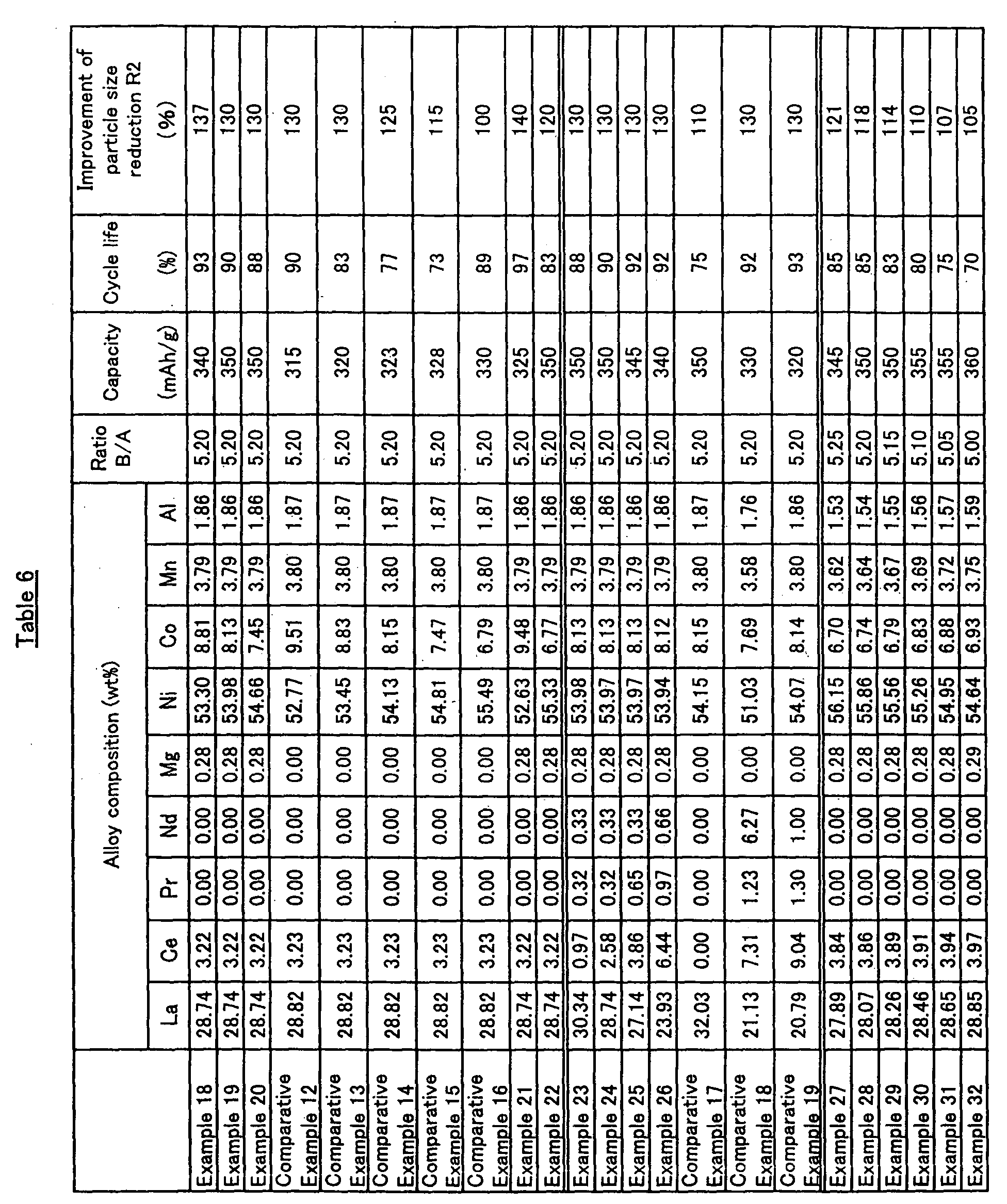
- the hydrogen absorbing alloy having 24 to 33% by weight of La, 6 to 9% by weight of Co and the atomic ratio B/A of 5.0 to 5.25, and which Mg is added to in an amount of 0.1 to 1.0% by weight, can result in a battery with higher capacity such as 340mAh/g or more, keeping cycle life unchanged.
- the ratio B/A means the sum of atomic ratios of, for example, Ni, Co, Mn and Al, excluding the elements in very small.amounts such as Mg and Ca, by designating the sum of atomic ratios of rare-earth metals such as La, Ce, Pr and Nd for one.
- the hydrogen absorbing alloy of the present invention can be manufactured by a dissolution method such as arc dissolution and high frequency dissolution, casting in a mold, table-casting, a rapid roll quenching method, gas atomization, disk-atomization or a spin-cup method, or a combination thereof.
- the hydrogen absorbing alloy of the present invention may be prepared in the following manner.
- Predetermined amounts of various elements may be weighed out and melted in a high-frequency furnace having an atmosphere of an inert gas (at 200 to 1,500 Torr) such as Ar gas.
- an element e.g., Mg or Ca
- Mg or Ca metals with high melting point such as Ni or Co are melted in order to prevent added components from evaporating or assure the safe operation.
- the resulting melt may be cast in a mold made of iron at a temperature of 1,300 to 1,600°C to form an ingot. Or the other methods mentioned above may be also used.
- the ingot may be heat-treated at a temperature of 800 to 1,200°C for 5 to 20 hours in an inert atmosphere (at 600 to 1,500 Torr), for example, of Ar gas.
- the hydrogen absorbing alloy prepared in the above-described manner may be ground to an average particle diameter of 4 to 70 ⁇ m in an inert atmosphere, for example, of Ar. Moreover, reduction in particle size by hydrogen absorption and desorption, so-called hydrogenation method, may be used. Thus, there can be obtained a hydrogen absorbing alloy in accordance with the present invention.
- the hydrogen absorbing alloy powder thus obtained may be formed into electrodes according to any well-known method. This can be accomplished, for example, by mixing the alloy powder with a binder selected from polyvinyl alcohol, cellulose derivatives (e.g., methylcellulose), PTFE, polyethylene oxide, high polymer latices and the like, kneading this mixture into a paste, and applying this paste to an electrically conducting three-dimensional support (e.g., foamed nickel or fibrous nickel) or an electrically conducting two-dimensional support (e.g., punching metal).
- a binder selected from polyvinyl alcohol, cellulose derivatives (e.g., methylcellulose), PTFE, polyethylene oxide, high polymer latices and the like, kneading this mixture into a paste, and applying this paste to an electrically conducting three-dimensional support (e.g., foamed nickel or fibrous nickel) or an electrically conducting two-dimensional support (e.g., punching metal).
- an electrically conducting filler such as carbon-graphite powder, Ni powder or Cu powder may be added in an amount of 0.1 to 10% by weight based on the alloy.
- Alkaline batteries using the hydrogen absorbing alloy of the present invention for the negative electrodes thereof have a long cycle life and exhibit an excellent high rate discharge property and low-temperature discharge characteristics, even when the alloy has a low cobalt content.
- Mm or rare earth elements such as La, Ce, Pr and Nd, metallic elements such as Ni, Co, Mn and Al, and Mg were weighed out so as to give each of the compositions shown in Table 1.
- Mg was used in the form of a MgNi 2 (m.p. 1100°C) alloy. These materials were melted in a high-frequency melting furnace, and the resulting melt was cast in a mold made of iron to form an ingot. As for the Mg-free alloy, the ingot is formed without using the Mg-Ni alloy.
- This ingot was heat-treated at 1,050°C for 6 hours in an atmosphere of Ar. Thereafter, using a grinder, this ingot was ground to an average particle diameter of 33 ⁇ m so as to obtain a hydrogen absorbing alloy powder. Analysis of this allow powder by XRD revealed that it had a CaCu 5 type crystal structure (FIG.1).
- a positive electrode which comprised a sintered electrode, was bonded to the aforesaid negative electrode with a polypropylene separator interposed therebetween. This assembly was immersed in a 6N KOH electrolyte to construct a battery.
- each of the batteries so constructed was tested in the following manner. First of all, at a temperature of 20°C, the battery was charged to 120% at 0.3C (90mA/g) based on the capacity of the negative electrode, rested for 30 minutes, and then discharged at 0.2C (60mA/g) until the battery voltage reached 0.6 V. When this cycle was repeated twenty times, the greatest discharge capacity was regarded as the "capacity" of the alloy. Subsequently, this battery was charged to 120% at 0.3C, and discharged at 2.0C (600mA/g). The capacity measured in this manner was regarded as the "high rate discharge capacity".
- the negative electrode was disassembled, placed in water, and exposed to ultrasonic waves from an ultrasonic horn so as to separate the alloy powder from the current collector.
- the particle size distribution after repeated charging and discharging was measured by means of a Microtrack analyzer to determine the average particle diameter D 50 ( ⁇ m).
- D 50 average particle diameter
- Mg-containing alloy has a better high rate discharge property and less liability to particle size reduction.
- Example 2 The compositions shown in Table 2 were employed for the formation of alloys in the same manner as Example 1 and capacities were measured in the same matter as Example 1 to examine the relationship between the La content and the capacity when magnesium is contained in the alloys. The results thus obtained are shown in Table 2. It can be seen from Table 2 that, in order to obtain an alloy having a high capacity, the La content in the alloy must be not less than 24% by weight.
- the D 50 is defined in such a way that, when the particle size distribution of the hydrogen absorbing alloy is measured and the frequencies of detection of various particle diameters are cumulatively added from smaller-diameter to larger-diameter particles, the particle diameter corresponding 50% of all particles is represented by D 50 .
- the alloy powders were prepared in the same manner as in Example 1 except the following: metallic Mg (m.p. 650°C) was used instead of the Mg-Ni alloy, and the mixture of Ni, Co, Mn, Al and some of rare-earth elements were melted in advance, and then after confirming the melting, the other of rare-earth elements and metallic Mg were added.
- metallic Mg m.p. 650°C
- the melting was carried out without addition of the metallic Mg.
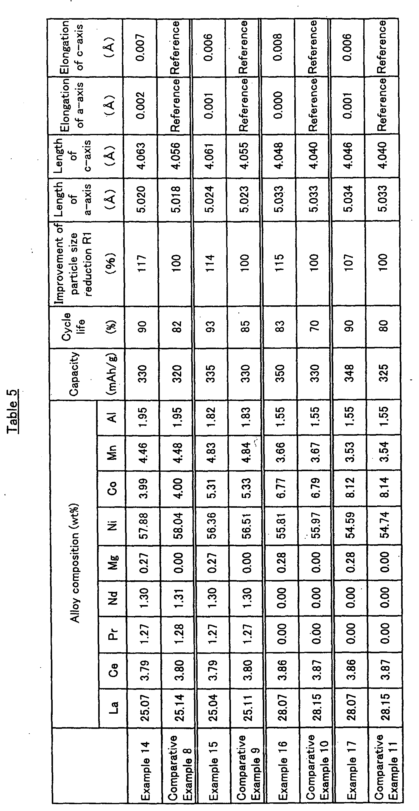
- the capacity in Table 5 was measured as follows. After dry-mixing hydrogen absorbing alloy 0.5 and Ni power 1.5 in the weight ratio, the mixture was molded in a mold with a diameter of 20mm to produce an electrode. The battery was charged to 125% at 0.5C (150mA/g), rested for 10 minutes, and then discharged at 0.5C (150mA/g) until the voltage difference based on mercury reference electrode (Hg/HgO) reached 0.6V. After this cycle was repeated ten times, the capacity was measured (as pellet capacity).
- the battery was charged at 0.3C (90mA/g) based on the capacity of the negative electrode, rested for 30 minutes, and then discharged at 0.2C (60mA/g) until the battery voltage reached 0.8V. After this cycle was repeated twenty times, in order to observe the degree of particle size reduction, the battery was disassembled and the alloy powder for the negative electrode was exposed to ultrasonic waves from an ultrasonic horn so as to separate the alloy powder from the current collector. The particle size distribution after repeated charging and discharging was measured by means of a Microtrack analyzer to determine the average particle diameter D 50 ( ⁇ m). The improvement of particle size reduction R1 was calculated.
- the diffraction patterns for the alloys shown in Table 5 were measured using a X-ray diffraction method for powder.
- the lattice constants were calculated based on the measurement data using a method of least squares.
- the alloy powders were prepared using MgNi 2 (m.p. 1100°C) in the same manner as in Example 1 except the following: the mixture of Ni, Co, Mn, Al and some of rare-earth elements were melted at first. Then, after the confirmation of the melting, the other of rare-earth elements and the Mg-Ni alloy were added for melting. As for the Mg-free alloys, the melting was carried out without addition of the metallic Mg.
- the alloys keeping La content of 24 to 33% by weight and Co content of 6 to 9% by weight in addition of 0.1 to 1.0% by weight of Mg with the B/A atomic ratio of 5.0 to 5.25, enables the achievement for the higher capacity such as 340mAh/g or more of capacity, although the cycle life therefor is as usual.
Landscapes
- Chemical & Material Sciences (AREA)
- Chemical Kinetics & Catalysis (AREA)
- Electrochemistry (AREA)
- General Chemical & Material Sciences (AREA)
- Engineering & Computer Science (AREA)
- Manufacturing & Machinery (AREA)
- Battery Electrode And Active Subsutance (AREA)
Abstract
Description
Because R is a rare earth element which is other than La, and M is at least one element chosen from the group of Mn, Al, Si, Sn, Fe, Cu, Ti, Zr, V or the like, the weighted averages of atomic weights are used for R and M. Excluding Mg and Ca, which are added in minor amounts, as well as unavoidable impurities, the ratio of elements belonging to "B" to those belonging to "A" is calculated as a B/A ratio according to the following equation: B/A ratio = (x+y+z)/(u+v).
wherein the length for a-axis (a-axis = b-axis) is in the range of 4.990 to 5.050Å, the length for c-axis is in the range of 4.030 to 4.070, regarding the lattice constants thereof. Comparing the lattice constants in these range between Mg-free and Mg-containing hydrogen absorbing alloys, the addition of Mg tends to increase the lattice constants. It has been particularly found that increase for c-axis is larger than that for a-axis so that the ratio of length of c-axis to length of a-axis, c/a, becomes larger.
| Alloy composition (wt%) | Capacity (mAh/g) | High rate discharge capacity (mAh/g) | Average particle diameter after size reduction (µm) | |||||||||
| La | Ce | Pr | Nd | Mg | Ni | Co | Mn | Al | ||||
| Example 1 | 25.04 | 3.16 | 1.90 | 1.30 | 0.27 | 56.61 | 5.31 | 4.58 | 1.82 | 305 | 220 | 25.31 |
| Comparative Example 1 | 25.45 | 3.21 | 1.94 | 1.32 | 0.00 | 53.76 | 8.64 | 3.77 | 1.92 | 302 | 162 | 23.14 |
| Alloy composition (wt%) | Capacity (mAh/g) | |||||||||
| La | Ce | Pr | Nd | Mg | Ni | Co | Mn | Al | ||
| Example 2 | 25.56 | 3.87 | 1.30 | 1.33 | 0.17 | 58.86 | 2.71 | 3.79 | 2.42 | 306 |
| Example 3 | 25.06 | 3.79 | 1.27 | 1.30 | 0.16 | 58.92 | 2.66 | 4.46 | 2.37 | 297 |
| Example 4 | 24.86 | 3.76 | 1.26 | 1.29 | 0.27 | 59.22 | 2.64 | 3.69 | 3.02 | 293 |
| Example 5 | 24.69 | 3.74 | 1.25 | 1.28 | 0.27 | 58.81 | 2.62 | 5.00 | 2.34 | 289 |
| Comparative Example 2 | 23.80 | 6.25 | 1.32 | 1.35 | 0.29 | 57.44 | 2.77 | 4.38 | 2.41 | 275 |
| Alloy composition (wt%) | Capacity (mAh/g) | |||||||||
| La | Ce | Pr | Nd | Mg | Ni | Co | Mn | Al | ||
| Example 6 | 26.59 | 3.87 | 1.30 | 1.33 | 0.17 | 58.94 | 2.71 | 3.80 | 2.30 | 306 |
| Example 7 | 25.53 | 3.86 | 1.29 | 1.33 | 0.28 | 58.80 | 2.71 | 3.79 | 2.42 | 301 |
| Example 8 | 24.97 | 3.78 | 1.27 | 1.30 | 0.55 | 58.69 | 2.65 | 4.44 | 2.36 | 286 |
| Comparative Example 3 | 24.99 | 3.15 | 1.27 | 1.30 | 1.09 | 58.74 | 2.65 | 4.45 | 2.37 | 270 |
| Alloy composition (wt%) | Improvement of particle size reduction R1 (%) | |||||||||
| La | Ce | Pr | Nd | Mg | Ni | Co | Mn | Al | ||
| Example 9 | 25.53 | 3.86 | 1.29 | 1.33 | 0.28 | 58.80 | 2.71 | 3.79 | 2.42 | 129.2 |
| Example 10 | 24.97 | 3.78 | 1.27 | 1.30 | 0.55 | 58.69 | 2.65 | 4.44 | 2.36 | 134.7 |
| Comparative Example 4 | 25.60 | 3.87 | 1.30 | 1.33 | 0.00 | 58.96 | 2.72 | 3.80 | 2.42 | 100.0 |
| Comparative Example 5 | 25.56 | 3.87 | 1.30 | 1.33 | 0.08 | 58.86 | 2.71 | 3.79 | 2.42 | 104.0 |
| Example 11 | 25.51 | 3.86 | 1.29 | 1.32 | 0.28 | 56.19 | 5.41 | 3.78 | 2.35 | 121.7 |
| Comparative Example 6 | 25.58 | 3.87 | 1.30 | 1.33 | 0.00 | 56.34 | 5.43 | 3.79 | 2.36 | 100.0 |
| Example 12 | 25.38 | 3.84 | 1.29 | 1.32 | 0.28 | 53.62 | 8.61 | 3.76 | 1.91 | 110.5 |
| Comparative Example 7 | 25.45 | 3.85 | 1.29 | 1.32 | 0.00 | 53.77 | 8.64 | 3.77 | 1.92 | 100.0 |
| Example 12 | 25.37 | 3.84 | 1.29 | 1.32 | 0.28 | 53.20 | 9.42 | 3.39 | 1.91 | 103.0 |
| Comparative Example 8 | 25.44 | 3.85 | 1.29 | 1.32 | 0.00 | 53.09 | 9.45 | 3.65 | 1.92 | 100.0 |
Claims (2)
- A hydrogen absorbing alloy having a CaCu5 type crystal structure in its principal phase and comprising Mg characterised by having a-axis length of 4.990 to 5.050 Å and c-axis length of 4.030 to 4.070 Å for the lattice constants in the CaCu5 type crystal structure.
- The hydrogen absorbing alloy according to claim 1 further comprising 6 % by weight or less of Co in the alloy.
Applications Claiming Priority (5)
| Application Number | Priority Date | Filing Date | Title |
|---|---|---|---|
| JP22199099 | 1999-08-05 | ||
| JP22199099 | 1999-08-05 | ||
| JP2000189040 | 2000-06-23 | ||
| JP2000189040 | 2000-06-23 | ||
| EP00115026A EP1075032B1 (en) | 1999-08-05 | 2000-07-24 | Hydrogen absorbing alloy and nickel-metal hydride rechargeable battery |
Related Parent Applications (1)
| Application Number | Title | Priority Date | Filing Date |
|---|---|---|---|
| EP00115026A Division EP1075032B1 (en) | 1999-08-05 | 2000-07-24 | Hydrogen absorbing alloy and nickel-metal hydride rechargeable battery |
Publications (2)
| Publication Number | Publication Date |
|---|---|
| EP1465270A2 true EP1465270A2 (en) | 2004-10-06 |
| EP1465270A3 EP1465270A3 (en) | 2004-10-13 |
Family
ID=26524615
Family Applications (2)
| Application Number | Title | Priority Date | Filing Date |
|---|---|---|---|
| EP00115026A Expired - Lifetime EP1075032B1 (en) | 1999-08-05 | 2000-07-24 | Hydrogen absorbing alloy and nickel-metal hydride rechargeable battery |
| EP04008375A Withdrawn EP1465270A3 (en) | 1999-08-05 | 2000-07-24 | Hydrogen absorbing alloy and nickel-metal hydride rechargeable battery |
Family Applications Before (1)
| Application Number | Title | Priority Date | Filing Date |
|---|---|---|---|
| EP00115026A Expired - Lifetime EP1075032B1 (en) | 1999-08-05 | 2000-07-24 | Hydrogen absorbing alloy and nickel-metal hydride rechargeable battery |
Country Status (6)
| Country | Link |
|---|---|
| US (2) | US6733724B1 (en) |
| EP (2) | EP1075032B1 (en) |
| KR (1) | KR100669593B1 (en) |
| CN (2) | CN1209831C (en) |
| DE (1) | DE60034848D1 (en) |
| TW (1) | TW488106B (en) |
Cited By (1)
| Publication number | Priority date | Publication date | Assignee | Title |
|---|---|---|---|---|
| US9997776B2 (en) | 2013-03-29 | 2018-06-12 | Panasonic Intellectual Property Management Co., Ltd. | Alloy powder for electrodes, negative electrode for nickel-metal hydride storage batteries including the same, and nickel-metal hydride storage battery including the same |
Families Citing this family (10)
| Publication number | Priority date | Publication date | Assignee | Title |
|---|---|---|---|---|
| EP1324407A1 (en) * | 2001-12-17 | 2003-07-02 | Mitsui Mining & Smelting Co., Ltd | Hydrogen storage material |
| KR100787104B1 (en) * | 2006-12-19 | 2007-12-21 | 한국생산기술연구원 | Ni-MH Battery |
| CN101589491B (en) * | 2007-07-24 | 2011-07-27 | 松下电器产业株式会社 | Negative-electrode material for nickel hydrogen battery, method of treating the same, and nickel hydrogen battery |
| CN101994030B (en) * | 2009-08-10 | 2013-01-30 | 北京有色金属研究总院 | Low-cost high-performance AB5 type hydrogen storage alloy and preparation method thereof |
| JPWO2012073418A1 (en) * | 2010-12-03 | 2014-05-19 | パナソニック株式会社 | Hydrogen storage alloy particles, electrode alloy powder and alkaline storage battery |
| JP5831407B2 (en) * | 2012-09-06 | 2015-12-09 | 信越化学工業株式会社 | Anode material for lithium ion battery |
| US10658660B2 (en) | 2016-09-26 | 2020-05-19 | Primearth Ev Energy Co., Ltd. | Nickel-metal hydride battery |
| EP3653296B1 (en) * | 2017-07-12 | 2023-12-13 | Japan Science and Technology Agency | Intermetallic compound, hydrogen storage/release material, catalyst and method for producing ammonia |
| CN108199009B (en) * | 2017-12-29 | 2020-05-15 | 东莞市朗泰通实业有限公司 | Low-temperature nickel-hydrogen battery with negative electrode double-sided coating |
| EP4095748A1 (en) * | 2021-05-28 | 2022-11-30 | Siemens Aktiengesellschaft | Production of a quality testing system |
Family Cites Families (18)
| Publication number | Priority date | Publication date | Assignee | Title |
|---|---|---|---|---|
| US3598383A (en) * | 1969-01-14 | 1971-08-10 | William H Moore | Method and apparatus for incorporating additives in a melt |
| US4126242A (en) * | 1974-07-16 | 1978-11-21 | The Research Institute For Iron, Steel And Other Metals Of The Tohoku University | Hydrogen-occluding alloy |
| NL7411045A (en) * | 1974-08-19 | 1976-02-23 | Philips Nv | RECHARGEABLE ELECTROCHEMICAL CELL. |
| JPS5830380B2 (en) * | 1979-10-23 | 1983-06-29 | 工業技術院長 | Mitsushi metal alloy for hydrogen storage |
| JPS5837374B2 (en) * | 1980-06-03 | 1983-08-16 | 工業技術院長 | Mitsushi Metal for Hydrogen Storage - Calcium Alloy |
| US4744946A (en) * | 1982-02-09 | 1988-05-17 | Japan Metals And Chemicals Co., Ltd. | Materials for storage of hydrogen |
| JPS60250557A (en) * | 1984-05-25 | 1985-12-11 | Matsushita Electric Ind Co Ltd | Enclosed type alkaline storage battery |
| JPH0756803B2 (en) | 1984-10-11 | 1995-06-14 | 松下電器産業株式会社 | Sealed alkaline storage battery |
| US4700371A (en) * | 1984-11-08 | 1987-10-13 | Hampshire Instruments, Inc. | Long life x-ray source target |
| US5034289A (en) * | 1989-02-23 | 1991-07-23 | Matsushita Electric Industrial Co., Ltd. | Alkaline storage battery and method of producing negative electrode thereof |
| JP2961179B2 (en) * | 1991-11-18 | 1999-10-12 | 工業技術院長 | Manufacturing method of hydrogen storage alloy |
| JPH0757769A (en) * | 1993-08-09 | 1995-03-03 | Toshiba Battery Co Ltd | Metal oxide-hydrogen secondary battery |
| ATE208437T1 (en) * | 1995-08-31 | 2001-11-15 | Santoku Metal Ind | HYDROGEN-ABSORBING RARE-EARTH METAL/NICKEL BASE ALLOY, PRODUCTION PROCESS AND NEGATIVE ELECTRODE FOR NICKEL-HYDROGEN SECONDARY BATTERY |
| DE69704003T2 (en) * | 1996-05-09 | 2001-06-07 | Mitsubishi Materials Corp., Tokio/Tokyo | Hydrogen absorbing alloy, process for its manufacture and electrode |
| JP3397981B2 (en) * | 1996-06-11 | 2003-04-21 | 三洋電機株式会社 | Hydrogen storage alloy and manufacturing method |
| FR2753991B1 (en) * | 1996-09-30 | 1998-12-11 | Centre Nat Rech Scient | INTERMETALLIC ALLOYS WITH HEXAGONAL STRUCTURE, THEIR PREPARATION, THEIR USE FOR THE PRODUCTION OF ELECTRODES |
| KR100218835B1 (en) * | 1997-05-28 | 1999-09-01 | 윤덕용 | MI / MH Secondary Battery Micro Metals and Nickel-Based Hydrogen Storage Alloys |
| KR100276018B1 (en) * | 1997-11-28 | 2000-12-15 | 니시무로 타이죠 | Ni-MH Secondary Battery |
-
2000
- 2000-07-19 TW TW089114408A patent/TW488106B/en not_active IP Right Cessation
- 2000-07-24 DE DE60034848T patent/DE60034848D1/en not_active Expired - Lifetime
- 2000-07-24 EP EP00115026A patent/EP1075032B1/en not_active Expired - Lifetime
- 2000-07-24 EP EP04008375A patent/EP1465270A3/en not_active Withdrawn
- 2000-08-03 US US09/631,491 patent/US6733724B1/en not_active Expired - Fee Related
- 2000-08-03 KR KR1020000045000A patent/KR100669593B1/en not_active Expired - Fee Related
- 2000-08-04 CN CNB001225286A patent/CN1209831C/en not_active Expired - Fee Related
- 2000-08-04 CN CN2005100057867A patent/CN1658412A/en active Pending
-
2004
- 2004-03-11 US US10/798,031 patent/US20040170520A1/en not_active Abandoned
Cited By (1)
| Publication number | Priority date | Publication date | Assignee | Title |
|---|---|---|---|---|
| US9997776B2 (en) | 2013-03-29 | 2018-06-12 | Panasonic Intellectual Property Management Co., Ltd. | Alloy powder for electrodes, negative electrode for nickel-metal hydride storage batteries including the same, and nickel-metal hydride storage battery including the same |
Also Published As
| Publication number | Publication date |
|---|---|
| US6733724B1 (en) | 2004-05-11 |
| TW488106B (en) | 2002-05-21 |
| CN1283877A (en) | 2001-02-14 |
| EP1075032B1 (en) | 2007-05-16 |
| EP1465270A3 (en) | 2004-10-13 |
| CN1658412A (en) | 2005-08-24 |
| KR20010021201A (en) | 2001-03-15 |
| KR100669593B1 (en) | 2007-01-15 |
| DE60034848D1 (en) | 2007-06-28 |
| EP1075032A1 (en) | 2001-02-07 |
| US20040170520A1 (en) | 2004-09-02 |
| CN1209831C (en) | 2005-07-06 |
Similar Documents
| Publication | Publication Date | Title |
|---|---|---|
| EP0293660B1 (en) | Hydrogen storage electrodes | |
| EP0609609B1 (en) | Method for manufacturing a hydrogen-absorbing alloy for a negative electrode | |
| US6733724B1 (en) | Hydrogen absorbing alloy and nickel-metal hydride rechargeable battery | |
| JP3201247B2 (en) | Sealed alkaline storage battery | |
| US9343737B2 (en) | Hydrogen-absorbing alloy powder, negative electrode, and nickel hydrogen secondary battery | |
| JP2022052729A (en) | Hydrogen storage alloy for alkaline storage battery | |
| US7198868B2 (en) | Alkaline storage battery | |
| EP1227165B1 (en) | Hydrogen-occluding alloy and process for producing the same | |
| JP3603013B2 (en) | Hydrogen storage alloy and nickel hydrogen secondary battery | |
| JP2001040442A (en) | Hydrogen storage alloy | |
| JPH0641663A (en) | Hydrogen storage alloy and its manufacture, and hydrogen storage alloy electrode | |
| EP0739990A1 (en) | Hydrogen storage alloy and electrode therefrom | |
| US5916519A (en) | Hydrogen storage alloy containing iron | |
| US5910379A (en) | Hydrogen absorbing alloy for a negative electrode of an alkaline storage battery | |
| JP3322452B2 (en) | Rare earth hydrogen storage alloy for alkaline storage batteries | |
| JP3459528B2 (en) | Method for producing hydrogen storage alloy for hydrogen storage alloy electrode | |
| US6420068B1 (en) | Hydrogen storage alloy electrode and method for manufacture thereof | |
| JP3519836B2 (en) | Hydrogen storage alloy electrode | |
| JP2001200324A (en) | Hydrogen storage alloy and nickel hydrogen secondary battery | |
| EP1096584A1 (en) | Hydrogen absorbing alloy for alkaline storage battery and method for production thereof, and hydrogen absorbing alloy electrode for alkaline storage battery and method for production thereof | |
| JP2001181763A (en) | Hydrogen storage alloy | |
| JP3351227B2 (en) | Hydrogen storage alloy powder for battery and its manufacturing method | |
| JP2002146457A (en) | Hydrogen storage alloy | |
| EP1324407A1 (en) | Hydrogen storage material | |
| JPH0831414A (en) | Hydrogen storage alloy for alkaline storage battery and manufacture thereof |
Legal Events
| Date | Code | Title | Description |
|---|---|---|---|
| PUAI | Public reference made under article 153(3) epc to a published international application that has entered the european phase |
Free format text: ORIGINAL CODE: 0009012 |
|
| PUAL | Search report despatched |
Free format text: ORIGINAL CODE: 0009013 |
|
| 17P | Request for examination filed |
Effective date: 20040406 |
|
| AC | Divisional application: reference to earlier application |
Ref document number: 1075032 Country of ref document: EP Kind code of ref document: P |
|
| AK | Designated contracting states |
Kind code of ref document: A2 Designated state(s): DE FR GB |
|
| AK | Designated contracting states |
Kind code of ref document: A3 Designated state(s): DE FR GB |
|
| AKX | Designation fees paid |
Designated state(s): DE FR GB |
|
| STAA | Information on the status of an ep patent application or granted ep patent |
Free format text: STATUS: THE APPLICATION IS DEEMED TO BE WITHDRAWN |
|
| 18D | Application deemed to be withdrawn |
Effective date: 20080201 |