EP1465212A1 - R-t-b based rare earth element permanent magnet - Google Patents
R-t-b based rare earth element permanent magnet Download PDFInfo
- Publication number
- EP1465212A1 EP1465212A1 EP03798556A EP03798556A EP1465212A1 EP 1465212 A1 EP1465212 A1 EP 1465212A1 EP 03798556 A EP03798556 A EP 03798556A EP 03798556 A EP03798556 A EP 03798556A EP 1465212 A1 EP1465212 A1 EP 1465212A1
- Authority
- EP
- European Patent Office
- Prior art keywords
- rare earth
- permanent magnet
- product
- earth permanent
- alloys
- Prior art date
- Legal status (The legal status is an assumption and is not a legal conclusion. Google has not performed a legal analysis and makes no representation as to the accuracy of the status listed.)
- Granted
Links
Images









Classifications
-
- C—CHEMISTRY; METALLURGY
- C22—METALLURGY; FERROUS OR NON-FERROUS ALLOYS; TREATMENT OF ALLOYS OR NON-FERROUS METALS
- C22C—ALLOYS
- C22C28/00—Alloys based on a metal not provided for in groups C22C5/00 - C22C27/00
-
- C—CHEMISTRY; METALLURGY
- C22—METALLURGY; FERROUS OR NON-FERROUS ALLOYS; TREATMENT OF ALLOYS OR NON-FERROUS METALS
- C22C—ALLOYS
- C22C30/00—Alloys containing less than 50% by weight of each constituent
-
- C—CHEMISTRY; METALLURGY
- C22—METALLURGY; FERROUS OR NON-FERROUS ALLOYS; TREATMENT OF ALLOYS OR NON-FERROUS METALS
- C22C—ALLOYS
- C22C38/00—Ferrous alloys, e.g. steel alloys
- C22C38/002—Ferrous alloys, e.g. steel alloys containing In, Mg, or other elements not provided for in one single group C22C38/001 - C22C38/60
-
- C—CHEMISTRY; METALLURGY
- C22—METALLURGY; FERROUS OR NON-FERROUS ALLOYS; TREATMENT OF ALLOYS OR NON-FERROUS METALS
- C22C—ALLOYS
- C22C38/00—Ferrous alloys, e.g. steel alloys
- C22C38/005—Ferrous alloys, e.g. steel alloys containing rare earths, i.e. Sc, Y, Lanthanides
-
- C—CHEMISTRY; METALLURGY
- C22—METALLURGY; FERROUS OR NON-FERROUS ALLOYS; TREATMENT OF ALLOYS OR NON-FERROUS METALS
- C22C—ALLOYS
- C22C38/00—Ferrous alloys, e.g. steel alloys
- C22C38/06—Ferrous alloys, e.g. steel alloys containing aluminium
-
- C—CHEMISTRY; METALLURGY
- C22—METALLURGY; FERROUS OR NON-FERROUS ALLOYS; TREATMENT OF ALLOYS OR NON-FERROUS METALS
- C22C—ALLOYS
- C22C38/00—Ferrous alloys, e.g. steel alloys
- C22C38/10—Ferrous alloys, e.g. steel alloys containing cobalt
-
- C—CHEMISTRY; METALLURGY
- C22—METALLURGY; FERROUS OR NON-FERROUS ALLOYS; TREATMENT OF ALLOYS OR NON-FERROUS METALS
- C22C—ALLOYS
- C22C38/00—Ferrous alloys, e.g. steel alloys
- C22C38/14—Ferrous alloys, e.g. steel alloys containing titanium or zirconium
-
- C—CHEMISTRY; METALLURGY
- C22—METALLURGY; FERROUS OR NON-FERROUS ALLOYS; TREATMENT OF ALLOYS OR NON-FERROUS METALS
- C22C—ALLOYS
- C22C38/00—Ferrous alloys, e.g. steel alloys
- C22C38/16—Ferrous alloys, e.g. steel alloys containing copper
-
- H—ELECTRICITY
- H01—ELECTRIC ELEMENTS
- H01F—MAGNETS; INDUCTANCES; TRANSFORMERS; SELECTION OF MATERIALS FOR THEIR MAGNETIC PROPERTIES
- H01F1/00—Magnets or magnetic bodies characterised by the magnetic materials therefor; Selection of materials for their magnetic properties
- H01F1/01—Magnets or magnetic bodies characterised by the magnetic materials therefor; Selection of materials for their magnetic properties of inorganic materials
- H01F1/03—Magnets or magnetic bodies characterised by the magnetic materials therefor; Selection of materials for their magnetic properties of inorganic materials characterised by their coercivity
- H01F1/032—Magnets or magnetic bodies characterised by the magnetic materials therefor; Selection of materials for their magnetic properties of inorganic materials characterised by their coercivity of hard-magnetic materials
- H01F1/04—Magnets or magnetic bodies characterised by the magnetic materials therefor; Selection of materials for their magnetic properties of inorganic materials characterised by their coercivity of hard-magnetic materials metals or alloys
- H01F1/047—Alloys characterised by their composition
- H01F1/053—Alloys characterised by their composition containing rare earth metals
- H01F1/055—Alloys characterised by their composition containing rare earth metals and magnetic transition metals, e.g. SmCo5
- H01F1/0555—Alloys characterised by their composition containing rare earth metals and magnetic transition metals, e.g. SmCo5 pressed, sintered or bonded together
- H01F1/0557—Alloys characterised by their composition containing rare earth metals and magnetic transition metals, e.g. SmCo5 pressed, sintered or bonded together sintered
-
- H—ELECTRICITY
- H01—ELECTRIC ELEMENTS
- H01F—MAGNETS; INDUCTANCES; TRANSFORMERS; SELECTION OF MATERIALS FOR THEIR MAGNETIC PROPERTIES
- H01F1/00—Magnets or magnetic bodies characterised by the magnetic materials therefor; Selection of materials for their magnetic properties
- H01F1/01—Magnets or magnetic bodies characterised by the magnetic materials therefor; Selection of materials for their magnetic properties of inorganic materials
- H01F1/03—Magnets or magnetic bodies characterised by the magnetic materials therefor; Selection of materials for their magnetic properties of inorganic materials characterised by their coercivity
- H01F1/032—Magnets or magnetic bodies characterised by the magnetic materials therefor; Selection of materials for their magnetic properties of inorganic materials characterised by their coercivity of hard-magnetic materials
- H01F1/04—Magnets or magnetic bodies characterised by the magnetic materials therefor; Selection of materials for their magnetic properties of inorganic materials characterised by their coercivity of hard-magnetic materials metals or alloys
- H01F1/047—Alloys characterised by their composition
- H01F1/053—Alloys characterised by their composition containing rare earth metals
- H01F1/055—Alloys characterised by their composition containing rare earth metals and magnetic transition metals, e.g. SmCo5
- H01F1/057—Alloys characterised by their composition containing rare earth metals and magnetic transition metals, e.g. SmCo5 and IIIa elements, e.g. Nd2Fe14B
- H01F1/0571—Alloys characterised by their composition containing rare earth metals and magnetic transition metals, e.g. SmCo5 and IIIa elements, e.g. Nd2Fe14B in the form of particles, e.g. rapid quenched powders or ribbon flakes
- H01F1/0575—Alloys characterised by their composition containing rare earth metals and magnetic transition metals, e.g. SmCo5 and IIIa elements, e.g. Nd2Fe14B in the form of particles, e.g. rapid quenched powders or ribbon flakes pressed, sintered or bonded together
- H01F1/0577—Alloys characterised by their composition containing rare earth metals and magnetic transition metals, e.g. SmCo5 and IIIa elements, e.g. Nd2Fe14B in the form of particles, e.g. rapid quenched powders or ribbon flakes pressed, sintered or bonded together sintered
-
- H—ELECTRICITY
- H01—ELECTRIC ELEMENTS
- H01F—MAGNETS; INDUCTANCES; TRANSFORMERS; SELECTION OF MATERIALS FOR THEIR MAGNETIC PROPERTIES
- H01F41/00—Apparatus or processes specially adapted for manufacturing or assembling magnets, inductances or transformers; Apparatus or processes specially adapted for manufacturing materials characterised by their magnetic properties
- H01F41/02—Apparatus or processes specially adapted for manufacturing or assembling magnets, inductances or transformers; Apparatus or processes specially adapted for manufacturing materials characterised by their magnetic properties for manufacturing cores, coils, or magnets
- H01F41/0253—Apparatus or processes specially adapted for manufacturing or assembling magnets, inductances or transformers; Apparatus or processes specially adapted for manufacturing materials characterised by their magnetic properties for manufacturing cores, coils, or magnets for manufacturing permanent magnets
Definitions
- the present invention relates to a method for manufacturing an R-T-B system rare earth permanent magnet containing, as main components, R (wherein R represents one or more rare earth elements, providing that the rare earth elements include Y), T (wherein T represents at least one transition metal element essentially containing Fe, or Fe and Co), and B (boron).
- rare earth permanent magnets an R-T-B system rare earth permanent magnet has been increasingly demanded year by year for the reasons that its magnetic properties are excellent and that its main component Nd is abundant as a source and relatively inexpensive.
- Japanese Patent Laid-Open No. 1-219143 discloses that the addition of 0.02 to 0.5 at % of Cu improves magnetic properties of the R-T-B system rare earth permanent magnet as well as heat treatment conditions.
- the method described in Japanese Patent Laid-Open No. 1-219143 is insufficient to obtain high magnetic properties required of a high performance magnet, such as a high coercive force (HcJ) and a high residual magnetic flux density (Br).
- the magnetic properties of an R-T-B system rare earth permanent magnet obtained by sintering depend on the sintering temperature. On the other hand, it is difficult to equalize the heating temperature throughout all parts of a sintering furnace in the scale of industrial manufacturing. Thus, the R-T-B system rare earth permanent magnet is required to obtain desired magnetic properties even when the sintering temperature is changed.
- a temperature range in which desired magnetic properties can be obtained is referred to as a suitable sintering temperature range herein.
- Japanese Patent Laid-Open No. 2000-234151 discloses the addition of Zr and/or Cr to obtain a high coercive force and a high residual magnetic flux density.
- Japanese Patent Laid-Open No. 2002-75717 discloses a method of uniformly dispersing a fine ZrB compound, NbB compound or HfB compound (hereinafter referred to as an M-B compound) into an R-T-B system rare earth permanent magnet containing Zr, Nb or Hf as well as Co, Al and Cu, followed by precipitation, so as to inhibit the grain growth in a sintering process and to improve magnetic properties and the suitable sintering temperature range.
- the suitable sintering temperature range is extended by the dispersion and precipitation of the M-B compound.
- the suitable sintering temperature range is narrow, such as approximately 20°C. Accordingly, to obtain high magnetic properties using a mass-production furnace or the like, it is desired to further extend the suitable sintering temperature range.
- it is effective to increase the additive amount of Zr. However, as the additive amount of Zr increases, the residual magnetic flux density decreases, and thus, high magnetic properties of interest cannot be obtained.
- the present inventors have found that when a specific product exists in the triple-point grain boundary phase or two-grain grain boundary phase of an R-T-B system rare earth permanent magnet with a certain composition containing Zr, the growth of an R 2 T 14 B phase (which exists as crystal grains) is inhibited during a sintering process so that the suitable sintering temperature range can be extended to an appropriate range.
- the present invention is made based on the above findings, and it provides an R-T-B system rare earth permanent magnet, which is a sintered body comprising a main phase consisting of an R 2 T 14 B phase (wherein R represents one or more rare earth elements (providing that the rare earth elements include Y), and T represents one or more transition metal elements essentially containing Fe, or Fe and Co), and a grain boundary phase containing a higher amount of R than the above main phase, wherein a platy or acicular product exists.
- R represents one or more rare earth elements (providing that the rare earth elements include Y), and T represents one or more transition metal elements essentially containing Fe, or Fe and Co)
- a grain boundary phase containing a higher amount of R than the above main phase, wherein a platy or acicular product exists.
- the major axis of the product is within the range between 30 and 600 nm and the minor axis thereof is within the range between 3 and 50 nm.
- the above sintered body preferably contains Zr, and the above product is preferably rich in Zr.
- This product has periodic composition fluctuations of Zr and R in the minor axis direction.
- the sintered body preferably has a composition consisting essentially of 28% to 33% by weight of R, 0.5% to 1.5% by weight of B, 0.03% to 0.3% by weight of Al, 0.3% or less by weight (excluding 0) of Cu, 0.05% to 0.2% by weight of Zr, 4% or less by weight (excluding 0) of Co, and the balance substantially being Fe.
- the sintered body preferably contains 0.1% to 0.15% by weight of Zr.
- the R-T-B system rare earth permanent magnet of the present invention is comprised of a sintered body at least containing a main phase consisting of an R 2 T 14 B phase (wherein R represents one or more rare earth elements (providing that the rare earth elements include Y), and T represents one or more types of transition metal elements essentially containing Fe, or Fe and Co), and a grain boundary phase containing a higher amount of R than the main phase.
- the R-T-B system rare earth permanent magnet of the present invention contains a triple-point grain boundary phase and a two-grain grain boundary phase that are the grain boundary phases of a sintered body.
- a product having the following features exists in the triple-point grain boundary phase and the two-grain grain boundary phase.
- FIGS. 1 and 2 show EDS (energy dispersive X-ray analyzer) profiles of a product existing in the triple-point grain boundary phase and a product existing in the two-grain grain boundary phase of the R-T-B system rare earth permanent magnet of type A in Example 1 described later.
- FIGS. 3 to 9 as shown below are also based on the observation of the R-T-B system rare earth permanent magnet of type A in Example 1 described later.
- this product is rich in Zr and further contains Nd as R and Fe as T.
- Nd As shown in FIGS. 1 and 2, this product is rich in Zr and further contains Nd as R and Fe as T.
- the R-T-B system rare earth permanent magnet contains Co or Cu, these elements may be contained in the product.
- FIGS. 3 and 4 are a TEM (Transmission Electron Microscope) photograph of the triple-point grain boundary phase and periphery thereof, of the permanent magnet of type A in Example 1.
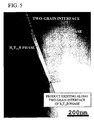
- FIG. 5 is a TEM photograph of the two-grain interface and periphery thereof, of the permanent magnet of type A.
- this product has a platy or acicular form. The determination of the form of the product is based on the observation of a cross section of the sintered body. Accordingly, it is difficult to determine from this observation whether the form is platy or acicular, and therefore, the form is described as being platy or acicular.
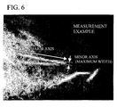
- This platy or acicular product has a major axis of 30 to 600 nm, a minor axis of 3 to 50 nm, and an axis ratio (major axis/minor axis) of 5 to 70.
- a method for measuring the major axis and minor axis of the product is shown in FIG. 6.
- FIG. 7 is a high resolution TEM photograph of the triple-point grain boundary phase and periphery thereof, of the R-T-B system rare earth permanent magnet of type A. As explained later, this product has a periodic fluctuation of the composition in the minor axis direction (in the direction of the arrow as shown in FIG. 7).
- FIG. 8 is a STEM (Scanning Transmission Electron Microscope) photograph of the product.
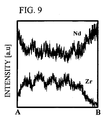
- FIG. 9 shows a concentration distribution of Nd and Zr expressed by change in the intensity of the spectrum of Nd-L ⁇ and Zr-L ⁇ lines that is obtained when an EDS line analysis is carried out on an analysis line A-B crossing over the product shown in FIG. 8.
- the concentration of Nd (R) is low in the region where the concentration of Zr is high.
- the concentration of Nd (R) is high in the region where the concentration of Zr is low.
- the product shows a periodic fluctuation of the composition in which Zr and Nd (R) are involved.
- R-T-B system rare earth permanent magnets obtained by two different manufacturing methods, their products were observed. More specifically, these products are types A and B in Example 1 described later.
- the methods for manufacturing an R-T-B system rare earth permanent magnet include a method of using as a starting alloy a single alloy having a desired composition (hereinafter referred to as a single method), and a method of using as starting alloys a plurality of alloys having different compositions (hereinafter referred to as a mixing method).
- a mixing method alloys containing an R 2 T 14 B phase as a main constituent (low R alloys) and alloys containing a higher amount of R than the low R alloys (high R alloys) are typically used as starting alloys.
- Both of the two manufacturing methods used herein are the mixing methods.
- the two methods are a method of adding Zr to the low R alloys (type A) and a method of adding Zr to the high R alloys (type B).
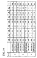
- the chemical compositions of low R alloys and high R alloys used for types A and B are shown in FIG. 10.
- FIG. 12 shows the results of the element mapping (area analysis) on a Zr-added low R alloy used for type A by EPMA (Electron Probe Micro Analyzer).
- FIG. 13 shows the results of the element mapping (area analysis) on a Zr-added high R alloy used for type B by EPMA (Electron Probe Micro Analyzer).
- the Zr-added low R alloy used for type A comprises at least two phases each having a different amount of Nd. However, in its low R alloy, Zr is uniformly dispersed, and it is not concentrated in a certain phase.
- both Zr and B are present in concentrated amounts, in a portion with a high concentration of Nd.
- Zr existing in type A is considerably uniformly distributed in a mother alloy, it is concentrated in a grain boundary phase (liquid phase) during the sintering process, and a nucleation starts in the liquid phase, then reaching the crystal growth. It then becomes a product, which extends to the easy-crystal grain growth direction because the cystal grows following a nucleation.
- Zr in type A has an extremely large axis ratio.
- type B since a Zr rich phase is formed in the mother alloy stage, the Zr concentration in a liquid phase is hardly increased in the sintering process. Thereafter, since the product is grown based on the existing Zr rich phase as a nucleus, it cannot grow freely. Thus, it is assumed that Zr in type B does not have a large axis ratio.
- the presence of the product enables to extend the suitable sintering temperature range, while inhibiting the decrease of the residual magnetic flux density.
- the present product has an anisotropic form.
- the form of the present product significantly differs from the isotropic form of a rare earth oxide (e.g., a spherical, in this case, the axis ratio is almost 1).
- the present product has a high probability to contact with an R 2 T 14 B phase, and further, the surface area of the product is larger than that of a spherical rare earth oxide. It is therefore considered that the present product inhibits the movement of grains through the grain boundary that is necessary for the grain growth, and that the suitable sintering temperature range is thereby extended only by the addition of a small amount of Zr.
- a product that is rich in Zr and has a large axis ratio is allowed to exist in the triple-point grain boundary phase or two-grain grain boundary phase of an R-T-B system rare earth permanent magnet containing Zr, so that the growth of the R 2 T 14 B phase is inhibited during the sintering process, thereby the suitable sintering temperature range is improved. Therefore, according to the present invention, a heat treatment on a large permanent magnet and a stable manufacturing of an R-T-B system rare earth permanent magnet using such a large heat treatment furnace can be easily carried out.
- an R-T-B system rare earth permanent magnet with high magnetic properties can be manufactured without causing the decrease of the residual magnetic flux density. This effect can be sufficiently exerted, when the concentration of oxygen in alloys or during the manufacturing process is reduced.
- the term chemical composition is used herein to mean a chemical composition obtained after sintering.
- the rare earth permanent magnet of the present invention contains 25% to 35% by weight of R.
- R is used herein to mean one or more rare earth elements selected from a group consisting of La, Ce, Pr, Nd, Sm, Eu, Gd, Tb, Dy, Ho, Er, Yb, Lu and Y. If the amount of R is less than 25% by weight, an R 2 T 14 B 1 phase as a main phase of the rare earth permanent magnet is not sufficiently generated. Accordingly, ⁇ -Fe or the like having soft magnetism is deposited and the coercive force significantly decreases. On the other hand, if the amount of R exceeds 35% by weight, the volume ratio of the R 2 T 14 B phase as a main phase decreases, and the residual magnetic flux density decreases.
- the amount of R is set between 25% and 35% by weight.
- the amount of R is preferably between 28% and 33% by weight, and more preferably between 29% and 32% by weight.
- Nd is abundant as a source and relatively inexpensive, it is preferable to use Nd as a main component of rare earth elements. Moreover, since the containment of Dy increases an anisotropic magnetic field, it is effective to contain Dy to improve the coercive force. Accordingly, it is desired to select Nd and Dy for R and to set the total amount of Nd and Dy between 25% and 33% by weight. In addition, in the above range, the amount of Dy is preferably between 0.1% and 8% by weight. It is desired that the amount of Dy is arbitrarily determined within the above range, depending on which is more important, a residual magnetic flux density or a coercive force.
- the amount of Dy is preferably set between 0.1% and 3.5% by weight.
- the amount of Dy is preferably set between 3.5% and 8% by weight.
- the rare earth permanent magnet of the present invention contains 0.5% to 4.5% by weight of boron (B). If the amount of B is less than 0.5% by weight, a high coercive force cannot be obtained. However, if the amount of B exceeds 4.5% by weight, the residual magnetic flux density is likely to decrease. Accordingly, the upper limit is set at 4.5% by weight.
- the amount of B is preferably between 0.5% and 1.5% by weight, and more preferably between 0.8% and 1.2% by weight.
- the R-T-B system rare earth permanent magnet of the present invention may contain Al and/or Cu within the range between 0.02% and 0.6% by weight.
- the containment of Al and/or Cu within the above range can impart a high coercive force, a strong corrosion resistance, and an improved temperature stability of magnetic properties to the obtained permanent magnet.
- the additive amount of Al is preferably between 0.03% and 0.3% by weight, and more preferably between 0.05% and 0.25% by weight.
- the additive amount of Cu is 0.3% or less by weight (excluding 0), preferably 0.15% or less by weight (excluding 0), and more preferably between 0.03% and 0.08% by weight.
- the R-T-B system rare earth permanent magnet of the present invention preferably contains Zr within the range between 0.03% and 0.25% by weight, so as to generate the above described product that is rich in Zr.
- Zr exerts the effect of inhibiting the abnormal grain growth in a sintering process and thereby makes the microstructure of the sintered body uniform and fine. Accordingly, when the amount of oxygen is low, Zr fully exerts its effect.
- the amount of Zr is preferably between 0.05% and 0.2% by weight, and more preferably between 0.1% and 0.15% by weight.
- the R-T-B system rare earth permanent magnet of the present invention contains 2,000 ppm or less oxygen. If it contains a large amount of oxygen, an oxide phase that is a non-magnetic component increases, thereby decreasing magnetic properties.
- the amount of oxygen contained in a sintered body is set at 2,000 ppm or less, preferably 1,500 ppm or less, and more preferably 1,000 ppm or less.
- the amount of oxygen is simply decreased, an oxide phase having a grain growth inhibiting effect decreases, so that the grain growth easily occurs in a process of obtaining full density increase during sintering.
- the R-T-B system rare earth permanent magnet to contains a certain amount of Zr, which exerts the effect of inhibiting the abnormal grain growth in a sintering process.
- the R-T-B system rare earth permanent magnet of the present invention contains Co in an amount of 4% or less by weight (excluding 0), preferably between 0.1% and 2.0% by weight, and more preferably between 0.3% and 1.0% by weight. Co forms a phase similar to that of Fe. Co has an effect to improve Curie temperature and the corrosion resistance of a grain boundary phase.
- Raw material is first subjected to strip casting in a vacuum or an inert gas atmosphere, or preferably an Ar atmosphere, so that low R alloys and high R alloys are obtained.
- the low R alloys can contain Cu and Al, as well as R, Fe, Co and B.
- the high R alloys can also contain Cu and Al, as well as R, Fe, Co and B.
- Zr may be contained either in the low R alloys or in the high R alloys. However, as stated above, Zr is preferably contained in the low R alloys in order that the product has a large axis ratio.
- each of the master alloys is crushed to a particle size of approximately several hundreds of ⁇ m.
- the crushing is preferably carried out in an inert gas atmosphere, using a stamp mill, a jaw crusher, a brown mill, etc. In order to improve rough crushability, it is effective to carry out crushing after the absorption of hydrogen. Otherwise, it is also possible to release hydrogen after absorbing it and then carry out crushing.
- the routine proceeds to a pulverizing process.
- a jet mill is mainly used, and crushed powders with a particle size of approximately several hundreds of ⁇ m are pulverized to a mean particle size between 3 and 5 ⁇ m.
- the jet mill is a method comprising releasing a high-pressure inert gas (e.g., nitrogen gas) from a narrow nozzle so as to generate a high-speed gas flow, accelerating the crushed powders with the high-speed gas flow, and making crushed powders hit against each other, the target, or the wall of the container, so as to pulverize the powders.
- a high-pressure inert gas e.g., nitrogen gas
- the pulverized low R alloy powders are mixed with the pulverized high R alloy powders in a nitrogen atmosphere.
- the mixing ratio of the low R alloy powders and the high R alloy powders may be approximately between 80 : 20 and 97 : 3 at a weight ratio.
- the mixing ratio may be approximately between 80 : 20 and 97 : 3 at a weight ratio.
- mixed powders comprising of the low R alloy powders and the high R alloy powders are filled in a tooling equipped with electromagnets, and they are compacted in a magnet field, in a state where their crystallographic axis is oriented by applying a magnetic field.
- This compacting may be carried out by applying a pressure of approximately 0.7 to 1.5 t/cm 2 in a magnetic field of 12.0 to 17.0 kOe.
- the compacted body is sintered in a vacuum or an inert gas atmosphere.
- the sintering temperature needs to be adjusted depending on various conditions such as a composition, a crushing method, the difference between particle size and particle size distribution, but the sintering may be carried out at 1,000°C to 1,100°C for about 1 to 5 hours.
- the obtained sintered body may be subjected to an aging treatment.
- the aging treatment is important for the control of a coercive force.
- the aging treatment is carried out in two steps, it is effective to retain the sintered body for a certain time at around 800°C and around 600°C.
- the coercive force increases. Accordingly, it is particularly effective in the mixing method.
- the coercive force significantly increases. Accordingly, when the aging treatment is carried out in a single step, it is appropriate to carry out it at around 600°C.
- Mother alloys(low R alloys and high R alloys)having compositions shown in FIG. 10 were preparedby the strip casting method. It is noted that Zr was contained in the low R alloys in type A, and that Zr was contained in the high R alloys in type B containing no B. Type C that contained no Zr was a comparative example in the present invention.
- a hydrogen crushing treatment was carried out, in which after hydrogen was absorbed into the mother alloys at room temperature, dehydrogenation was carried out thereon at 600°C for 1 hour in an Ar atmosphere.
- the atmosphere was controlled at an oxygen concentration less than 100 ppm throughout processes, from a hydrogen treatment (recovery after a crushing process) to sintering (input into a sintering furnace).
- two-step crushing is carried out, which includes crushing process and pulverizing process.
- the crushing process was omitted in the present Examples.
- the low R alloys were mixed with the high R alloys for 30 minutes in the combinations of types A, B and C shown in FIG. 10. In all the types A to C, the mixing ratio between the low R alloys and the high R alloys was 90 : 10.
- the mixture was subjected to the pulverizing with a jet mill to a mean particle size of 5.0 ⁇ m.
- the obtained fine powders were compacted in a magnetic field of 14.0 kOe by applying a pressure of 1.2 t/cm 2 , so as to obtain a compacted body.
- the obtained compacted body was sintered at 1,010°C to 1,090°C for 4 hours in a vacuum atmosphere, followed by quenching. Thereafter, the obtained sintered body was subjected to a two-step aging treatment consisting of treatments of 800°C ⁇ 1 hour and 550°C ⁇ 2.5 hours (both in an Ar atmosphere).
- composition of the obtained permanent magnets are shown in the column "Composition of sintered body" in FIG. 10.
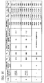
- the amount of oxygen and the amount of nitrogen of each permanent magnet are shown in FIG. 15. As shown in the figure, the amount of oxygen is 1, 000 ppm or less and that of nitrogen is 500 ppm or less, and thus, both the values are low.
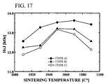
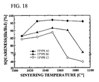
- the magnetic properties of the obtained permanent magnets were measured with a B-H tracer. The results are shown in FIGS. 15 to 18.
- Br represents a residual magnetic flux density
- HcJ represents a coercive force.
- a squareness (Hk/HcJ) is an index of magnet performance, and it represents an angular degree in the second quadrant of a magnetic hysteresis loop.
- Hk means an external magnetic field strength obtained when the magnetic flux density becomes 90% of the residual magnetic flux density in the second quadrant of a magnetic hysteresis loop.
- Type C that contains no Zr has the highest value at each of the sintering temperatures.
- Type A has almost the same value as type C.
- Type A can control a decrease in the residual magnetic flux density (Br) to a minimum by the addition of Zr and can obtain a value of 13.9 kG or greater within the sintering temperature range between 1,030°C and 1,070°C.
- type A has a higher value than types B and C at each of the sintering temperatures. Specifically, a value of 13.0 kOe or greater can be obtained by type A within the sintering temperature range between 1,030°C and 1,070°C.
- type A has a higher value than types B and C at each of the sintering temperatures. Specifically, a value of 95% or more can be obtained by type A within the sintering temperature range between 1,030°C and 1,070°C.
- type C has a squareness (Hk/HcJ) of 40% or less at a sintering temperature of 1,090°C, and therefore it cannot be considered that type C is a practical material for industrial production.
- the R-T-B system rare earth permanent magnet of type A has a suitable sintering temperature range of 40°C or more.
- the sizes of the above products in R-T-B system rare earth permanent magnets sintered at 1,050°C were measured.
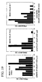
- the measurement results for the product in type A are shown in FIG. 19, and the measurement results for the product in type B are shown in FIG. 20.
- the mean values of the major axis, minor axis, and axis ratio of the products in types A and B are shown in FIG. 15.
- the samples for the observation were prepared by the ion-milling method, and they were observed by JEM-3010 manufactured by Japan Electron Optics Laboratory Co., Ltd.
- the axis ratio exceeds 10 both in types A and B, and thus, it is found that the products have a platy or acicular form with a large axis ratio.
- Type A in which Zr was added to the low R alloys has a major axis (mean value) of longer than 300 nm and has a high axis ratio of more than 20. No products were observed in type C containing no Zr.
- Types A and B each containing the product have a higher coercive force (HcJ) and a higher squareness (Hk/HcJ) than type C containing no products at each of the sintering temperatures.
- HcJ coercive force
- Hk/HcJ squareness
- type C contains abnormally grown coarse crystal grains (constituting an R 2 T 14 B phase) in its sintered microstructure. No such coarse crystal grains were observed in the sintered microstructures of types A and B.
- type A containing the product having a longer major axis and a larger axis ratio has a higher coercive force (HcJ) and a higher squareness (Hk/HcJ).
- type A has a wider suitable sintering temperature range than type B.
- the major axis of the product is preferably 200 nm or longer, and more preferably 300 nm or longer.
- the axis ratio is preferably 15 or greater, and more preferably 20 or greater.
- a hydrogen crushing treatment was carried out, in which after hydrogen was absorbed into the mother alloys at room temperature, dehydrogenation was carried out thereon at 600°C for 1 hour in an Ar atmosphere.
- the atmosphere was controlled at an oxygen concentration less than 100 ppm throughout processes, from a hydrogen treatment (recovery after a crushing process) to sintering (input into a sintering furnace).
- the low R alloys were mixed with the high R alloys for 30 minutes in the combinations of types D to G shown in FIG. 21.
- the mixing ratio between the low R alloys and the high R alloys was 90 : 10.
- the mixture was subjected to the pulverizing with a jet mill to a mean particle size of 4.1 ⁇ m.
- the obtained fine powders were compacted in a magnetic field of 17.0 kOe by applying a pressure of 1.2 t/cm 2 , so as to obtain a compacted body.
- the obtained compacted body was sintered at 1,010°C to 1,090°C for 4 hours in a vacuum atmosphere, followed by quenching. Thereafter, the obtained sintered body was subjected to a two-step aging treatment consisting of treatments of 800°C ⁇ 1 hour and 550°C ⁇ 2.5 hours (both in an Ar atmosphere).
- Example 2 The same measurement as in Example 1 was carried out on the obtained permanent magnets. The results are shown in FIG. 22.
- the amount of oxygen was 1, 000 ppm or less and that of nitrogen was 500 ppm or less.
- a product that was rich in Zr was observed in each of the samples, and the product had a major axis within the range between 250 and 450 nm, a minor axis within the range between 10 and 20 nm, on average.
- the axis ratio exceeded 15.
- type D containing 0.11% by weight of Zr is compared with type E containing 0.15% by weight of Zr, the residual magnetic flux density (Br) is equivalent.
- type E containing a larger amount of Zr has a squareness of 95% or more even at a sintering temperature of 1,090°C.
- the squareness of type D is reduced to 50% or less at the sintering temperature of 1, 090°C.
- types F and G both containing a larger amount of Dy than type E has a value of 15.6 or greater, which is equivalent to the value of type E.
- types F and G have a higher coercive force (HcJ) than type E.
- type F can obtain a squareness (Hk/HcJ) of 95% or more within the range of the sintering temperature between 1,030°C and 1,090°C, and type G can obtain the same squareness within the range between 1, 030°C and 1,070°C.
- both types F and G have a suitable sintering temperature range of 40°C or more, and it is found that high magnetic properties can be consistently obtained in a wide sintering temperature range.
- the low R alloys were mixed with the high R alloys for 30 minutes in the combinations as shown in FIG. 23. Thereafter, the mixture was subjected to the pulverizing with a jet mill to a mean particle size of 4. 0 ⁇ m.
- the obtained fine powders were compacted in a magnetic field under the same conditions as in Example 1. Thereafter, in the case of type H, the compacted body was sintered at 1,070°C for 4 hours, and in the case of type I, it was sintered at 1,020°C for 4 hours.
- the obtained sintered bodies of both types H and I were subjected to a two-step aging treatment consisting of treatments of 800°C ⁇ 1 hour and 550°C ⁇ 2.5 hours.
- the composition, the amount of oxygen, and the amount of nitrogen of each of the obtained sintered bodies are shown in FIG. 23.
- magnetic properties thereof are shown in FIG. 24.
- the magnetic properties of types D to G prepared in Example 2 are also shown in FIG. 24.
- an R-T-B system rare earth permanent magnet capable of inhibiting the grain growth while keeping a decrease in magnetic properties to a minimum, and improving the suitable sintering temperature range, can be obtained.
Landscapes
- Chemical & Material Sciences (AREA)
- Engineering & Computer Science (AREA)
- Materials Engineering (AREA)
- Mechanical Engineering (AREA)
- Metallurgy (AREA)
- Organic Chemistry (AREA)
- Power Engineering (AREA)
- Crystallography & Structural Chemistry (AREA)
- Inorganic Chemistry (AREA)
- Manufacturing & Machinery (AREA)
- Hard Magnetic Materials (AREA)
- Powder Metallurgy (AREA)
Abstract
Description
Claims (9)
- An R-T-B system rare earth permanent magnet, comprising a sintered body comprising:a main phase consisting of an R2T14B phase (wherein R represents one or more rare earth elements (providing that the rare earth elements include Y), and T represents one or more transition metal elements essentially containing Fe, or Fe and Co); anda grain boundary phase containing a higher amount of R than said main phase, wherein a platy or acicular product exists.
- An R-T-B system rare earth permanent magnet according to claim 1, wherein said product exists along said R2T14B phase.
- An R-T-B system rare earth permanent magnet according to claim 1 or 2, wherein the mean value of the major axis/minor axis of said product is 5 or greater.
- An R-T-B system rare earth permanent magnet according to claim 3, wherein the major axis of said product is within the range between 30 and 600 nm and the minor axis thereof is within the range between 3 and 50 nm.
- An R-T-B system rare earth permanent magnet according to claim 1, wherein said sintered body contains Zr and said product is rich in Zr.
- An R-T-B system rare earth permanent magnet according to claim 5, wherein said product has periodic composition fluctuations of Zr and R in said minor axis direction.
- An R-T-B system rare earth permanent magnet according to claim 1, wherein the amount of oxygen contained in said sintered body is 2,000 ppm or less.
- An R-T-B system rare earth permanent magnet according to claim 1, wherein said sintered body has a composition consisting essentially of 28% to 33% by weight of R, 0.5% to 1.5% by weight of B, 0.03% to 0.3% by weight of Al, 0.3 or less by weight (excluding 0) of Cu, 0.05% to 0.2% by weight of Zr, 4% or less by weight (excluding 0) of Co, and the balance substantially being Fe.
- An R-T-B system rare earth permanent magnet according to claim 8, wherein said sintered body contains 0.1% to 0.15% by weight of Zr.
Applications Claiming Priority (5)
| Application Number | Priority Date | Filing Date | Title |
|---|---|---|---|
| JP2002287033 | 2002-09-30 | ||
| JP2002287033 | 2002-09-30 | ||
| JP2003092891 | 2003-03-28 | ||
| JP2003092891 | 2003-03-28 | ||
| PCT/JP2003/012488 WO2004029996A1 (en) | 2002-09-30 | 2003-09-30 | R-t-b based rare earth element permanent magnet |
Publications (3)
| Publication Number | Publication Date |
|---|---|
| EP1465212A1 true EP1465212A1 (en) | 2004-10-06 |
| EP1465212A4 EP1465212A4 (en) | 2005-03-30 |
| EP1465212B1 EP1465212B1 (en) | 2007-01-24 |
Family
ID=32044659
Family Applications (2)
| Application Number | Title | Priority Date | Filing Date |
|---|---|---|---|
| EP03798556A Expired - Lifetime EP1465212B1 (en) | 2002-09-30 | 2003-09-30 | R-t-b based rare earth element permanent magnet |
| EP03798555A Expired - Lifetime EP1460652B1 (en) | 2002-09-30 | 2003-09-30 | R-t-b rare earth permanent magnet |
Family Applications After (1)
| Application Number | Title | Priority Date | Filing Date |
|---|---|---|---|
| EP03798555A Expired - Lifetime EP1460652B1 (en) | 2002-09-30 | 2003-09-30 | R-t-b rare earth permanent magnet |
Country Status (6)
| Country | Link |
|---|---|
| US (1) | US7311788B2 (en) |
| EP (2) | EP1465212B1 (en) |
| JP (2) | JP4076175B2 (en) |
| CN (2) | CN100334661C (en) |
| DE (2) | DE60311421T2 (en) |
| WO (2) | WO2004029996A1 (en) |
Families Citing this family (21)
| Publication number | Priority date | Publication date | Assignee | Title |
|---|---|---|---|---|
| US7199690B2 (en) * | 2003-03-27 | 2007-04-03 | Tdk Corporation | R-T-B system rare earth permanent magnet |
| WO2005015580A1 (en) * | 2003-08-12 | 2005-02-17 | Neomax Co., Ltd. | R-t-b sintered magnet and rare earth alloy |
| JP4702522B2 (en) * | 2005-02-23 | 2011-06-15 | Tdk株式会社 | R-T-B system sintered magnet and manufacturing method thereof |
| WO2009004994A1 (en) | 2007-06-29 | 2009-01-08 | Tdk Corporation | Rare earth magnet |
| EP2555207B1 (en) | 2010-03-30 | 2017-11-01 | TDK Corporation | Rare earth sintered magnet, method for producing the same, motor, and automobile |
| WO2011125590A1 (en) * | 2010-03-31 | 2011-10-13 | 日東電工株式会社 | Permanent magnet and manufacturing method for permanent magnet |
| JP5303738B2 (en) * | 2010-07-27 | 2013-10-02 | Tdk株式会社 | Rare earth sintered magnet |
| JP5729051B2 (en) * | 2011-03-18 | 2015-06-03 | Tdk株式会社 | R-T-B rare earth sintered magnet |
| CN102290181B (en) * | 2011-05-09 | 2014-03-12 | 中国科学院宁波材料技术与工程研究所 | Low cost, high coercive force, high energy product sintered rare earth permanent magnet and its preparation method |
| US9607742B2 (en) * | 2011-10-13 | 2017-03-28 | Tdk Corporation | R-T-B based alloy strip, and R-T-B based sintered magnet and method for producing same |
| JP6414059B2 (en) * | 2013-07-03 | 2018-10-31 | Tdk株式会社 | R-T-B sintered magnet |
| JP6314380B2 (en) * | 2013-07-23 | 2018-04-25 | Tdk株式会社 | Rare earth magnet, electric motor, and device including electric motor |
| DE112014003694B4 (en) | 2013-08-09 | 2023-06-29 | Tdk Corporation | R-T-B based sintered magnet and rotary machine |
| CN106165026B (en) * | 2014-03-27 | 2019-02-15 | 日立金属株式会社 | R-T-B-based alloy powder and method for producing the same, and R-T-B-based sintered magnet and method for producing the same |
| JP6269279B2 (en) * | 2014-04-15 | 2018-01-31 | Tdk株式会社 | Permanent magnet and motor |
| WO2017132075A1 (en) | 2016-01-28 | 2017-08-03 | Urban Mining Company | Grain boundary engineering of sintered magnetic alloys and the compositions derived therefrom |
| JP2018056524A (en) * | 2016-09-30 | 2018-04-05 | Tdk株式会社 | Coil component |
| JP7196468B2 (en) | 2018-08-29 | 2022-12-27 | 大同特殊鋼株式会社 | RTB system sintered magnet |
| US11232890B2 (en) | 2018-11-06 | 2022-01-25 | Daido Steel Co., Ltd. | RFeB sintered magnet and method for producing same |
| JP7379837B2 (en) | 2019-03-20 | 2023-11-15 | Tdk株式会社 | RTB series permanent magnet |
| CN111613408B (en) * | 2020-06-03 | 2022-05-10 | 福建省长汀金龙稀土有限公司 | R-T-B series permanent magnet material, raw material composition, preparation method and application thereof |
Family Cites Families (24)
| Publication number | Priority date | Publication date | Assignee | Title |
|---|---|---|---|---|
| JPS6274054A (en) | 1985-09-27 | 1987-04-04 | Hitachi Metals Ltd | Permanent magnet alloy |
| JPH01103805A (en) | 1987-07-30 | 1989-04-20 | Tdk Corp | Permanent magnet |
| JPH01196104A (en) * | 1988-02-01 | 1989-08-07 | Tdk Corp | Manufacture of rare earth alloy magnet |
| JP2720040B2 (en) | 1988-02-26 | 1998-02-25 | 住友特殊金属株式会社 | Sintered permanent magnet material and its manufacturing method |
| US5000800A (en) | 1988-06-03 | 1991-03-19 | Masato Sagawa | Permanent magnet and method for producing the same |
| JP3724513B2 (en) | 1993-11-02 | 2005-12-07 | Tdk株式会社 | Method for manufacturing permanent magnet |
| JP3237053B2 (en) | 1996-07-25 | 2001-12-10 | 三菱マテリアル株式会社 | Rare earth magnet material powder having excellent magnetic properties and method for producing the same |
| JP2891215B2 (en) | 1996-12-17 | 1999-05-17 | 三菱マテリアル株式会社 | Method for producing rare earth-B-Fe based sintered magnet excellent in corrosion resistance and magnetic properties |
| JPH10259459A (en) | 1997-01-14 | 1998-09-29 | Mitsubishi Materials Corp | Raw alloy for producing rare earth magnet powder and method for producing rare earth magnet powder using this raw alloy |
| JPH1064712A (en) | 1997-07-18 | 1998-03-06 | Hitachi Metals Ltd | R-fe-b rare earth sintered magnet |
| US6494968B1 (en) * | 1998-02-06 | 2002-12-17 | Toda Kogyo Corporation | Lamellar rare earth-iron-boron-based magnet alloy particles, process for producing the same and bonded magnet produced therefrom |
| DE69815146T2 (en) * | 1998-08-28 | 2004-02-26 | Showa Denko K.K. | ALLOY FOR USE IN PRODUCING R-T-B BASED MAGNETIC MAGNETS AND METHOD FOR PRODUCING R-T-B BASED MAGNETIC MAGNETS |
| EP0994493B1 (en) * | 1998-10-14 | 2003-09-10 | Hitachi Metals, Ltd. | R-T-B sintered permanent magnet |
| JP2000234151A (en) | 1998-12-15 | 2000-08-29 | Shin Etsu Chem Co Ltd | R-Fe-B rare earth permanent magnet material |
| DE60028659T2 (en) * | 1999-06-08 | 2007-05-31 | Shin-Etsu Chemical Co., Ltd. | Thin band of a permanent magnet alloy based on rare earths |
| JP2001323343A (en) * | 2000-05-12 | 2001-11-22 | Isuzu Motors Ltd | High performance rare earth permanent magnet alloy and method for producing the same |
| DE60131699T2 (en) * | 2000-06-13 | 2008-11-20 | Shin-Etsu Chemical Co., Ltd. | Permanent magnet materials based on R-Fe-B |
| JP3951099B2 (en) | 2000-06-13 | 2007-08-01 | 信越化学工業株式会社 | R-Fe-B rare earth permanent magnet material |
| WO2002013209A2 (en) * | 2000-08-03 | 2002-02-14 | Sanei Kasei Co., Limited | Nanocomposite permanent magnet |
| JP2002164239A (en) | 2000-09-14 | 2002-06-07 | Hitachi Metals Ltd | Manufacturing method of rare earth sintered magnet, ring magnet, and arc segment magnet |
| JP3452254B2 (en) * | 2000-09-20 | 2003-09-29 | 愛知製鋼株式会社 | Method for producing anisotropic magnet powder, raw material powder for anisotropic magnet powder, and bonded magnet |
| US7192493B2 (en) * | 2002-09-30 | 2007-03-20 | Tdk Corporation | R-T-B system rare earth permanent magnet and compound for magnet |
| US7255752B2 (en) * | 2003-03-28 | 2007-08-14 | Tdk Corporation | Method for manufacturing R-T-B system rare earth permanent magnet |
| US7314531B2 (en) * | 2003-03-28 | 2008-01-01 | Tdk Corporation | R-T-B system rare earth permanent magnet |
-
2003
- 2003-09-29 US US10/675,230 patent/US7311788B2/en not_active Expired - Lifetime
- 2003-09-30 CN CNB038013126A patent/CN100334661C/en not_active Expired - Lifetime
- 2003-09-30 DE DE60311421T patent/DE60311421T2/en not_active Expired - Lifetime
- 2003-09-30 EP EP03798556A patent/EP1465212B1/en not_active Expired - Lifetime
- 2003-09-30 DE DE60317767T patent/DE60317767T2/en not_active Expired - Lifetime
- 2003-09-30 WO PCT/JP2003/012488 patent/WO2004029996A1/en not_active Ceased
- 2003-09-30 EP EP03798555A patent/EP1460652B1/en not_active Expired - Lifetime
- 2003-09-30 WO PCT/JP2003/012487 patent/WO2004029995A1/en not_active Ceased
- 2003-09-30 CN CNB038010542A patent/CN100334659C/en not_active Expired - Lifetime
- 2003-09-30 JP JP2004539580A patent/JP4076175B2/en not_active Expired - Lifetime
- 2003-09-30 JP JP2004539579A patent/JP4763290B2/en not_active Expired - Lifetime
Also Published As
| Publication number | Publication date |
|---|---|
| CN100334659C (en) | 2007-08-29 |
| EP1465212A4 (en) | 2005-03-30 |
| US20040177899A1 (en) | 2004-09-16 |
| DE60311421T2 (en) | 2007-10-31 |
| US7311788B2 (en) | 2007-12-25 |
| JPWO2004029996A1 (en) | 2006-01-26 |
| DE60311421D1 (en) | 2007-03-15 |
| EP1465212B1 (en) | 2007-01-24 |
| CN100334661C (en) | 2007-08-29 |
| CN1572004A (en) | 2005-01-26 |
| JPWO2004029995A1 (en) | 2006-01-26 |
| CN1557005A (en) | 2004-12-22 |
| EP1460652A1 (en) | 2004-09-22 |
| WO2004029996A1 (en) | 2004-04-08 |
| DE60317767T2 (en) | 2008-11-27 |
| JP4076175B2 (en) | 2008-04-16 |
| EP1460652A4 (en) | 2005-04-20 |
| DE60317767D1 (en) | 2008-01-10 |
| EP1460652B1 (en) | 2007-11-28 |
| JP4763290B2 (en) | 2011-08-31 |
| WO2004029995A1 (en) | 2004-04-08 |
Similar Documents
| Publication | Publication Date | Title |
|---|---|---|
| EP1465212B1 (en) | R-t-b based rare earth element permanent magnet | |
| US7192493B2 (en) | R-T-B system rare earth permanent magnet and compound for magnet | |
| US7255752B2 (en) | Method for manufacturing R-T-B system rare earth permanent magnet | |
| EP1641000B1 (en) | R-t-b based rare earth permanent magnet and method for production thereof | |
| EP1462531B1 (en) | R-T-B system rare earth permanent magnet | |
| EP4044202B1 (en) | Method of preparing a high-coercivity sintered ndfeb magnet | |
| CN108695034B (en) | R-T-B sintered magnet | |
| CN107622853B (en) | R-T-B based rare earth element permanent magnet | |
| US7314531B2 (en) | R-T-B system rare earth permanent magnet | |
| EP1460651B1 (en) | Method for producing r-t-b based rare earth element permanent magnet | |
| JPH06124812A (en) | Nitride magnet powder and its synthesizing method | |
| JPH05121223A (en) | Manufacturing method of rare earth-iron-nitrogen permanent magnet |
Legal Events
| Date | Code | Title | Description |
|---|---|---|---|
| PUAI | Public reference made under article 153(3) epc to a published international application that has entered the european phase |
Free format text: ORIGINAL CODE: 0009012 |
|
| 17P | Request for examination filed |
Effective date: 20040521 |
|
| AK | Designated contracting states |
Kind code of ref document: A1 Designated state(s): DE FR GB NL |
|
| REG | Reference to a national code |
Ref country code: DE Ref legal event code: R079 Ref document number: 60311421 Country of ref document: DE Free format text: PREVIOUS MAIN CLASS: H01F0001080000 Ipc: C22C0001040000 |
|
| A4 | Supplementary search report drawn up and despatched |
Effective date: 20050216 |
|
| RIC1 | Information provided on ipc code assigned before grant |
Ipc: 7H 01F 1/053 B Ipc: 7C 22C 33/02 B Ipc: 7C 22C 1/04 A Ipc: 7H 01F 1/057 B Ipc: 7H 01F 1/047 B |
|
| 17Q | First examination report despatched |
Effective date: 20050523 |
|
| GRAP | Despatch of communication of intention to grant a patent |
Free format text: ORIGINAL CODE: EPIDOSNIGR1 |
|
| GRAS | Grant fee paid |
Free format text: ORIGINAL CODE: EPIDOSNIGR3 |
|
| GRAA | (expected) grant |
Free format text: ORIGINAL CODE: 0009210 |
|
| AK | Designated contracting states |
Kind code of ref document: B1 Designated state(s): DE FR GB NL |
|
| REG | Reference to a national code |
Ref country code: GB Ref legal event code: FG4D |
|
| REF | Corresponds to: |
Ref document number: 60311421 Country of ref document: DE Date of ref document: 20070315 Kind code of ref document: P |
|
| REG | Reference to a national code |
Ref country code: DE Ref legal event code: R096 Ref document number: 60311421 Country of ref document: DE Effective date: 20070315 |
|
| ET | Fr: translation filed | ||
| PLBE | No opposition filed within time limit |
Free format text: ORIGINAL CODE: 0009261 |
|
| STAA | Information on the status of an ep patent application or granted ep patent |
Free format text: STATUS: NO OPPOSITION FILED WITHIN TIME LIMIT |
|
| 26N | No opposition filed |
Effective date: 20071025 |
|
| REG | Reference to a national code |
Ref country code: DE Ref legal event code: R097 Ref document number: 60311421 Country of ref document: DE Effective date: 20071025 |
|
| PGFP | Annual fee paid to national office [announced via postgrant information from national office to epo] |
Ref country code: NL Payment date: 20150809 Year of fee payment: 13 |
|
| REG | Reference to a national code |
Ref country code: FR Ref legal event code: PLFP Year of fee payment: 14 |
|
| REG | Reference to a national code |
Ref country code: NL Ref legal event code: MM Effective date: 20161001 |
|
| PG25 | Lapsed in a contracting state [announced via postgrant information from national office to epo] |
Ref country code: NL Free format text: LAPSE BECAUSE OF NON-PAYMENT OF DUE FEES Effective date: 20161001 |
|
| REG | Reference to a national code |
Ref country code: FR Ref legal event code: PLFP Year of fee payment: 15 |
|
| REG | Reference to a national code |
Ref country code: FR Ref legal event code: PLFP Year of fee payment: 16 |
|
| PGFP | Annual fee paid to national office [announced via postgrant information from national office to epo] |
Ref country code: GB Payment date: 20220811 Year of fee payment: 20 Ref country code: DE Payment date: 20220621 Year of fee payment: 20 |
|
| PGFP | Annual fee paid to national office [announced via postgrant information from national office to epo] |
Ref country code: FR Payment date: 20220808 Year of fee payment: 20 |
|
| P01 | Opt-out of the competence of the unified patent court (upc) registered |
Effective date: 20230512 |
|
| REG | Reference to a national code |
Ref country code: DE Ref legal event code: R071 Ref document number: 60311421 Country of ref document: DE |
|
| REG | Reference to a national code |
Ref country code: GB Ref legal event code: PE20 Expiry date: 20230929 |
|
| PG25 | Lapsed in a contracting state [announced via postgrant information from national office to epo] |
Ref country code: GB Free format text: LAPSE BECAUSE OF EXPIRATION OF PROTECTION Effective date: 20230929 |