EP1465026A1 - Watch case - Google Patents
Watch case Download PDFInfo
- Publication number
- EP1465026A1 EP1465026A1 EP03007208A EP03007208A EP1465026A1 EP 1465026 A1 EP1465026 A1 EP 1465026A1 EP 03007208 A EP03007208 A EP 03007208A EP 03007208 A EP03007208 A EP 03007208A EP 1465026 A1 EP1465026 A1 EP 1465026A1
- Authority
- EP
- European Patent Office
- Prior art keywords
- plates
- box according
- receive
- box
- assembly
- Prior art date
- Legal status (The legal status is an assumption and is not a legal conclusion. Google has not performed a legal analysis and makes no representation as to the accuracy of the status listed.)
- Withdrawn
Links
Images

Classifications
-
- G—PHYSICS
- G04—HOROLOGY
- G04B—MECHANICALLY-DRIVEN CLOCKS OR WATCHES; MECHANICAL PARTS OF CLOCKS OR WATCHES IN GENERAL; TIME PIECES USING THE POSITION OF THE SUN, MOON OR STARS
- G04B37/00—Cases
- G04B37/22—Materials or processes of manufacturing pocket watch or wrist watch cases
- G04B37/225—Non-metallic cases
-
- G—PHYSICS
- G04—HOROLOGY
- G04B—MECHANICALLY-DRIVEN CLOCKS OR WATCHES; MECHANICAL PARTS OF CLOCKS OR WATCHES IN GENERAL; TIME PIECES USING THE POSITION OF THE SUN, MOON OR STARS
- G04B37/00—Cases
- G04B37/08—Hermetic sealing of openings, joints, passages or slits
- G04B37/081—Complete encasings for wrist or pocket watches also comprising means for hermetic sealing of the winding stem and crown
-
- G—PHYSICS
- G04—HOROLOGY
- G04B—MECHANICALLY-DRIVEN CLOCKS OR WATCHES; MECHANICAL PARTS OF CLOCKS OR WATCHES IN GENERAL; TIME PIECES USING THE POSITION OF THE SUN, MOON OR STARS
- G04B37/00—Cases
- G04B37/14—Suspending devices, supports or stands for time-pieces insofar as they form part of the case
- G04B37/1486—Arrangements for fixing to a bracelet
Definitions
- the present invention relates to boxes for watches of the type provided of a bracelet, which have three essential functions, that is to protect the movement inside, give the watch a part important of its aesthetics, and ensure the fixation of the bracelet.
- a piece of this type is the subject of document EP 0131 276. It comprises a box forming a platinum and consisting of a stack of transparent material plates. In this box, the plates are assembled by means of feet, glued to the plate upper, and screws engaged in each of them. Such a solution allows to minimize the metal part, but poses problems of rigidity and longevity, the glue may lose its adhesion.
- the purpose of the present invention is to allow the production of watches with a great lightness of structure, thanks to the extremely simple component parts of the box, while providing great safety both in terms of rigidity and longevity.
- the strap fixing means are advantageously mounted on one sleepers of each of the organs and formed of at least one protuberance, intended to be engaged in a cutout of the bracelet and extending parallel to the beam. It is thus possible to ensure a rigid fixing and simple bracelet to box.
- the structure of the assembly means can be particularly simple if one of the crosspieces of each member is permanently fixed to the beam whose it is integral, thus forming a T-piece.
- the protuberance intended to fix the bracelet can be formed by at least two pins permanently fixed to the crosspiece of the T-piece. These pins extend parallel to the beam to the vicinity of the second crosspiece.
- the second crosspiece is provided with recesses arranged for receive the ends of the pins.
- the lower plate is provided a drowning, practiced in its face adjacent to the median plate and intended to receive movement, and a hole extending from the recess to the edge of the box to allow the engagement of a rod setting the time.
- the rigidity of the box can be improved thanks to the fact that the plates extremes and the sleepers have, some of the protrusions, the other cutouts arranged so as to receive the protuberances. In this way, relative displacement of the plates with reference to the assembly members is impossible.
- seals are interposed between the plates, each housed in a groove in one of the plates.
- the box has a particularly attractive aesthetic when the plates are all made of transparent material.
- the middle plate can be provided with a recess, the bottom constitutes the dial and which defines a housing intended to receive the watch hands.
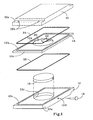
- the watch shown in the drawing has a box of general shape rectangular made from a stack of plates and more particularly provided with two end plates, one upper 10, the other lower 12, and a middle plate 14. It further comprises housed in the box, an assembly comprising a movement 16 provided with a time-setting rod 18 and display means formed by a dial 20 and needles 22.
- the plates 10 and 12 are provided with grooves identified by the letter a extending laterally from one edge to the other of the plate. Recesses identified by the letter b are made in the bottom of the grooves 10a and 12a. The function of the gorges and the hollows will be specified later.
- the lower plate 12 is provided with a recess 12c intended to receive the movement 16.
- a hole 12d connecting one of the lateral faces of the plate 12 to the recess 12c allows the passage of the time-setting rod 18.
- the plate 14 includes a recess 14a pierced in its upper face and the bottom of which forms the dial 20.
- the recesses 12c and 14a define housings intended to receive the assembly formed by movement 16 and display means, the hands 22 being disposed in the recess 14a, while the movement 16 is in drowning 12c.
- the bottom of the recess 14a is, of course, pierced with a hole for connecting the hands to the arranged movement shafts to wear them.
- the plate 14 could be thicker and the recess 14a be arranged to receive movement 16 and the display means, its wall then being drilled with a hole to allow the passage of the setting rod time. It could also be provided with recesses on its two faces, one intended to receive movement 16, the other the needles 22, the wall separating the two recesses in lieu of dial 20.
- the plates 10, 12 and 14 can be made of tempered glass, the plate median 14 advantageously being made of translucent and colored glass for give the box an original appearance.
- seals 24 and 26 are interposed respectively between the plates 10 and 14 on the one hand, 12 and 14 on the other hand. These seals 24 and 26 are housed and positioned respectively in grooves 12e and 14b formed in the upper faces of the plates 12 and 14. It goes without saying that the time-setting rod 18 will also be provided a seal. However, this has not been shown in the drawing.
- the plates are assembled by two identical members 28 (fig 2 and 3), arranged in opposition and each comprising a beam 30 adjoining the lateral faces of the plates 12, 14 and 16 assembled, which form the edge of the box, and two cross members 32 and 34 each fixed to one end of the beam 30 and each forming two arms identified by the letters a and b .
- the arms 32a and 34a extend in abutment against the plates 10 and 12 respectively to apply them against the middle plate 14.
- the beam 30 and the crosspieces 32 and 34 are dimensioned so that their arms 32a and 34a are respectively housed in the grooves 10a and 12a of the plates 10 and 12.
- the arms 32a and 34a include pins identified by the letter c , visible in Figure 2, and which are arranged to engage in the recesses identified by the letter b of the plates 10 and 12, to position them.
- the cross member 32 is fixed to the beam 30 by means of screws 36, while the cross member 34 is permanently fixed to the beam 30 to form together a T-piece
- the box as described is intended to be worn on the wrist by means a bracelet not shown in the drawing, by means of assembly formed of two protrusions 38 in the form of pins permanently fixed in the arm 34b of the cross member 34.
- the pins extend parallel to the beam 30 and slightly beyond.
- the arms 32b are provided non-referenced countersinks in which the ends of the pins 38 are engaged, so as to reinforce the rigidity of the assembly.
- the hollows 10b and 12b could be replaced by holes through plates 10, 12 and 14 right through, and the organs 28 present a symmetry with respect to a plane perpendicular to the plates and arranged in the longitudinal axis of the beam. In this way, the members 28 can be put in place without worry about their orientation. In addition, the plates are positioned in all their thickness.
- the plate stack could have another shape than parallelepiped.
- the assembly members are arranged adjacent to the edge of the box, their shape being adapted for marry.
Abstract
Description
La présente invention se rapporte aux boítes pour montres du type muni d'un bracelet, qui ont trois fonctions essentielles, soit protéger le mouvement qui se trouve à l'intérieur, conférer à la montre une part importante de son esthétique, et assurer la fixation du bracelet.The present invention relates to boxes for watches of the type provided of a bracelet, which have three essential functions, that is to protect the movement inside, give the watch a part important of its aesthetics, and ensure the fixation of the bracelet.
Certaines pièces sont agencées de manière à présenter une structure très légère, basée sur la transparence. Une pièce de ce type fait l'objet du document EP 0131 276. Elle comporte une boíte formant platine et constituée d'un empilement de plaques en matériau transparent. Dans cette boíte, les plaques sont assemblées au moyen de pieds, collés sur la plaque supérieure, et de vis engagées dans chacun d'eux. Une telle solution permet de limiter au minimum la partie métallique, mais pose des problèmes de rigidité et de longévité, la colle pouvant perdre de son adhérence.Some parts are arranged so as to have a very structured light, based on transparency. A piece of this type is the subject of document EP 0131 276. It comprises a box forming a platinum and consisting of a stack of transparent material plates. In this box, the plates are assembled by means of feet, glued to the plate upper, and screws engaged in each of them. Such a solution allows to minimize the metal part, but poses problems of rigidity and longevity, the glue may lose its adhesion.
Le but de la présente invention est de permettre la réalisation de montres présentant une grande légèreté de structure, grâce aux formes extrêmement simples des pièces constitutives de la boíte, tout en offrant une grande sécurité tant au niveau de la rigidité que de la longévité.The purpose of the present invention is to allow the production of watches with a great lightness of structure, thanks to the extremely simple component parts of the box, while providing great safety both in terms of rigidity and longevity.
La boíte selon l'invention est destinée à recevoir un ensemble comportant un mouvement de montre et des moyens d'affichage. Selon l'invention, elle comporte :
- deux plaques extrêmes de forme plane, l'une supérieure et transparente, l'autre inférieure, et
- au moins une plaque médiane, interposée entre les plaques extrêmes, lesdites plaques étant munies d'au moins une découpe formant un logement destiné à recevoir tout ou partie du mouvement et des moyens d'affichage et fermé par les plaques inférieure et supérieure, les faces latérales de ces plaques définissant la tranche de la boíte,
- des moyens d'assemblage des plaques les unes sur les autres, et
- des moyens de fixation d'un bracelet.
- two planar end plates, one upper and transparent, the other lower, and
- at least one middle plate, interposed between the end plates, said plates being provided with at least one cutout forming a housing intended to receive all or part of the movement and display means and closed by the lower and upper plates, the faces lateral of these plates defining the edge of the box,
- means for assembling the plates on top of each other, and
- means for attaching a bracelet.
Une telle boíte est caractérisée en ce que les moyens d'assemblage comprennent deux organes disposés en opposition et comportant chacun :
- une poutre attenante à la tranche de la boíte, et
- deux traverses fixées chacune à l'une des extrémités de la poutre et solidaires de celle-ci, et s'étendant, en appui, au-dessus des plaques extrêmes pour les appliquer contre la plaque médiane.
- a beam adjoining the edge of the box, and
- two crosspieces each fixed to one end of the beam and integral with the latter, and extending, in abutment, above the end plates to apply them against the middle plate.
Les moyens de fixation du bracelet sont avantageusement montés sur l'une des traverses de chacun des organes et formés d'au moins une protubérance, destinée à être engagée dans une découpe du bracelet et s'étendant parallèlement à la poutre. Il est ainsi possible d'assurer une fixation rigide et simple du bracelet à la boíte.The strap fixing means are advantageously mounted on one sleepers of each of the organs and formed of at least one protuberance, intended to be engaged in a cutout of the bracelet and extending parallel to the beam. It is thus possible to ensure a rigid fixing and simple bracelet to box.
La structure des moyens d'assemblage peut être particulièrement simple si l'une des traverses de chaque organe est fixée à demeure à la poutre dont elle est solidaire, formant ainsi une pièce en T. Dans ce cas, la protubérance destinée à fixer le bracelet peut être formée d'au moins deux goupilles fixées à demeure à la traverse de la pièce en T. Ces goupilles s'étendent parallèlement à la poutre jusqu'au voisinage de la deuxième traverse.The structure of the assembly means can be particularly simple if one of the crosspieces of each member is permanently fixed to the beam whose it is integral, thus forming a T-piece. In this case, the protuberance intended to fix the bracelet can be formed by at least two pins permanently fixed to the crosspiece of the T-piece. These pins extend parallel to the beam to the vicinity of the second crosspiece.
Dans le but de garantir une grande rigidité des moyens de fixation du bracelet, la deuxième traverse est munie de creusures agencées pour recevoir les extrémités des goupilles.In order to guarantee high rigidity of the fixing means of the bracelet, the second crosspiece is provided with recesses arranged for receive the ends of the pins.
Afin d'éviter la multiplication des plaques, la plaque inférieure est munie d'une noyure, pratiquée dans sa face attenante à la plaque médiane et destinée à recevoir le mouvement, et d'un trou s'étendant de la noyure jusqu'à la tranche de la boíte pour permettre l'engagement d'une tige de mise à l'heure.In order to avoid the multiplication of plates, the lower plate is provided a drowning, practiced in its face adjacent to the median plate and intended to receive movement, and a hole extending from the recess to the edge of the box to allow the engagement of a rod setting the time.
La rigidité de la boíte peut être améliorée grâce au fait que les plaques extrêmes et les traverses comportent, les unes des protubérances, les autres des découpes disposées de manière à recevoir les protubérances. De la sorte, un déplacement relatif des plaques en référence aux organes d'assemblage est impossible.The rigidity of the box can be improved thanks to the fact that the plates extremes and the sleepers have, some of the protrusions, the other cutouts arranged so as to receive the protuberances. In this way, relative displacement of the plates with reference to the assembly members is impossible.
Pour éviter que de l'eau ou de la poussière ne pénètre dans la boíte, des joints d'étanchéité sont interposés entre les plaques, chacun logé dans une gorge pratiquée dans l'une des plaques.To prevent water or dust from entering the box, seals are interposed between the plates, each housed in a groove in one of the plates.
La boíte présente une esthétique particulièrement attractive lorsque les plaques sont toutes en matériau transparent.The box has a particularly attractive aesthetic when the plates are all made of transparent material.
Dans cette montre, la plaque médiane peut être munie d'une creusure dont le fond constitue le cadran et qui définit un logement destiné à recevoir les aiguilles de la montre.In this watch, the middle plate can be provided with a recess, the bottom constitutes the dial and which defines a housing intended to receive the watch hands.
D'autres avantages et caractéristiques de l'invention ressortiront de la description qui va suivre, faite en regard du dessin annexé, dans lequel:
- la figure 1 représente, en éclaté, la partie centrale d'une boíte selon l'invention, munie d'un mouvement de montre et de moyens d'affichage, et
- les figures 2 et 3 sont des vues respectivement de côté et en perspective d'une montre dans laquelle la boíte est munie de ses moyens d'assemblage.
- FIG. 1 shows, in exploded view, the central part of a box according to the invention, provided with a watch movement and display means, and
- Figures 2 and 3 are respectively side and perspective views of a watch in which the box is provided with its assembly means.
La montre représentée au dessin comporte une boíte de forme générale
parallélépipédique réalisée à partir d'un empilement de plaques et plus
particulièrement munie de deux plaques extrêmes, l'une supérieure 10,
l'autre inférieure 12, et une plaque médiane 14. Elle comprend, en outre,
logé dans la boíte, un ensemble comprenant un mouvement 16 muni d'une
tige de mise à l'heure 18 et des moyens d'affichage formés d'un cadran 20
et d'aiguilles 22.The watch shown in the drawing has a box of general shape
rectangular made from a stack of plates and more
particularly provided with two end plates, one upper 10,
the other lower 12, and a
Les plaques 10 et 12 sont munies de gorges identifiées par la lettre a
s'étendant latéralement d'un bord à l'autre de la plaque. Des creusures
identifiées par la lettre b sont pratiquées dans le fond des gorges 10a et 12a.
La fonction des gorges et des creusures sera précisée plus loin. The
La plaque inférieure 12 est munie d'une noyure 12c destinée à recevoir le
mouvement 16. Un trou 12d reliant l'une des faces latérales de la plaque 12
à la noyure 12c permet le passage de la tige de mise à l'heure 18. La plaque
14 comprend une noyure 14a percée dans sa face supérieure et dont le fond
forme le cadran 20.The
Les noyures 12c et 14a définissent des logements destinés à recevoir
l'ensemble formé du mouvement 16 et des moyens d'affichage, les aiguilles
22 étant disposées dans la noyure 14a, alors que le mouvement 16 se trouve
dans la noyure 12c. Le fond de la noyure 14a est, bien entendu, percé d'un
trou permettant de relier les aiguilles aux arbres du mouvement agencés
pour les porter.The
En variante, la plaque 14 pourrait être plus épaisse et la noyure 14a être
agencée pour recevoir le mouvement 16 et les moyens d'affichage, sa paroi
étant alors percée d'un trou pour permettre le passage de la tige de mise à
l'heure. Elle pourrait aussi être munie de noyures sur ses deux faces, l'une
destinée à recevoir le mouvement 16, l'autre les aiguilles 22, la paroi
séparant les deux noyures tenant lieu de cadran 20.Alternatively, the
Dans une autre variante, représentée aux figures 2 et 3, le cadran 20 est
rapporté et la plaque 14 est percée de part en part.In another variant, shown in Figures 2 and 3, the
Les plaques 10, 12 et 14 peuvent être réalisées en verre trempé, la plaque
médiane 14 étant avantageusement en verre translucide et coloré pour
conférer à la boíte un aspect original.The
Afin d'éviter que de l'eau ou de la poussière ne pénètre dans la boíte
jusqu'au mouvement 16, des joints d'étanchéité 24 et 26 (figure 1) sont
respectivement interposés entre les plaques 10 et 14 d'une part, 12 et 14
d'autre part. Ces joints 24 et 26 sont logés et positionnés respectivement
dans des gorges 12e et 14b pratiquées dans les faces supérieures des plaques
12 et 14. Il va de soi que la tige de mise à l'heure 18 sera également munie
d'un joint d'étanchéité. Celui-ci n'a toutefois pas été représenté au dessin. To prevent water or dust from entering the box
up to
L'assemblage des plaques est assuré par deux organes 28 identiques (fig 2 et
3), disposés en opposition et comportant chacun une poutre 30 attenante aux
faces latérales des plaques 12, 14 et 16 assemblées, qui forment la tranche
de la boíte, et deux traverses 32 et 34 fixées chacune à l'une des extrémités
de la poutre 30 et formant chacune deux bras identifiés par les lettres a et b.
Les bras 32a et 34a s'étendent en appui contre respectivement les plaques
10 et 12 pour les appliquer contre la plaque médiane 14.The plates are assembled by two identical members 28 (fig 2 and 3), arranged in opposition and each comprising a
La poutre 30 et les traverses 32 et 34 sont dimensionnées de manière à ce
que leurs bras 32a et 34a soient respectivement logés dans les gorges 10a et
12a des plaques 10 et 12. Les bras 32a et 34a comportent des tétons
identifiés par la lettre c, visibles sur la figure 2, et qui sont disposés de
manière à s'engager dans les creusures identifiées par la lettre b des plaques
10 et 12, pour les positionner.The
La traverse 32 est fixée sur la poutre 30 au moyen de vis 36, alors que la
traverse 34 est fixée à demeure à la poutre 30 pour former ensemble une
pièce en T.The
La boíte telle que décrite est destinée à être portée au poignet au moyen
d'un bracelet non représenté au dessin, par des moyens d'assemblage
formés de deux protubérances 38 se présentant sous forme de goupilles
fixées à demeure dans le bras 34b de la traverse 34. Les goupilles s'étendent
parallèlement à la poutre 30 et légèrement au-delà. Les bras 32b sont munis
de noyures non référencées et dans lesquelles les extrémités des goupilles 38
sont engagées, de manière à renforcer la rigidité de l'ensemble.The box as described is intended to be worn on the wrist by means
a bracelet not shown in the drawing, by means of assembly
formed of two
Il est, bien entendu, possible d'imaginer de nombreuses variantes, sans pour
autant sortir du cadre de l'invention. Ainsi, les creusures 10b et 12b
pourraient être remplacées par des trous traversant les plaques 10, 12 et 14
de part en part, et les organes 28 présenter une symétrie par rapport à un
plan perpendiculaire aux plaques et disposé dans l'axe longitudinal de la
poutre. De la sorte, les organes 28 peuvent être mis en place sans se
préoccuper de leur orientation. De plus, les plaques sont positionnées dans
toute leur épaisseur.It is, of course, possible to imagine many variations, without
as well go beyond the scope of the invention. Thus, the
Dans une autre variante, l'empilement de plaque pourrait présenter une autre forme que parallélépipédique. Dans tous les cas, les organes d'assemblage sont disposés attenants à la tranche de la boíte, leur forme étant adaptée pour l'épouser.In another variant, the plate stack could have another shape than parallelepiped. In all cases, the assembly members are arranged adjacent to the edge of the box, their shape being adapted for marry.
Claims (10)
Priority Applications (1)
| Application Number | Priority Date | Filing Date | Title |
|---|---|---|---|
| EP03007208A EP1465026A1 (en) | 2003-03-29 | 2003-03-29 | Watch case |
Applications Claiming Priority (1)
| Application Number | Priority Date | Filing Date | Title |
|---|---|---|---|
| EP03007208A EP1465026A1 (en) | 2003-03-29 | 2003-03-29 | Watch case |
Publications (1)
| Publication Number | Publication Date |
|---|---|
| EP1465026A1 true EP1465026A1 (en) | 2004-10-06 |
Family
ID=32842710
Family Applications (1)
| Application Number | Title | Priority Date | Filing Date |
|---|---|---|---|
| EP03007208A Withdrawn EP1465026A1 (en) | 2003-03-29 | 2003-03-29 | Watch case |
Country Status (1)
| Country | Link |
|---|---|
| EP (1) | EP1465026A1 (en) |
Citations (3)
| Publication number | Priority date | Publication date | Assignee | Title |
|---|---|---|---|---|
| EP0131267A1 (en) * | 1983-07-08 | 1985-01-16 | Eta SA Fabriques d'Ebauches | Portable device with visible mechanism |
| WO1998057237A1 (en) * | 1997-06-12 | 1998-12-17 | Finger Hansjoerg | Watch case |
| FR2774486A1 (en) * | 1998-01-30 | 1999-08-06 | Vuillemin Regnier | RELEASABLE HOLDING DEVICE AT THE END OF A STRAP FOR A WATCH CASE WITH AN INTERCHANGEABLE STRAP |
-
2003
- 2003-03-29 EP EP03007208A patent/EP1465026A1/en not_active Withdrawn
Patent Citations (3)
| Publication number | Priority date | Publication date | Assignee | Title |
|---|---|---|---|---|
| EP0131267A1 (en) * | 1983-07-08 | 1985-01-16 | Eta SA Fabriques d'Ebauches | Portable device with visible mechanism |
| WO1998057237A1 (en) * | 1997-06-12 | 1998-12-17 | Finger Hansjoerg | Watch case |
| FR2774486A1 (en) * | 1998-01-30 | 1999-08-06 | Vuillemin Regnier | RELEASABLE HOLDING DEVICE AT THE END OF A STRAP FOR A WATCH CASE WITH AN INTERCHANGEABLE STRAP |
Similar Documents
| Publication | Publication Date | Title |
|---|---|---|
| EP0098239B1 (en) | Wrist watch with a strap hinged to the case | |
| EP2636328A1 (en) | Device for attaching a watchstrap to a watch middle | |
| FR2509058A1 (en) | MOUNT OF EYEWEAR WITH SOFT LINKS | |
| EP0770939B1 (en) | Timepiece comprising a case with a clockwork movement therein | |
| EP0873543A1 (en) | Watch frame comprising a case and a supporting device | |
| CA1051966A (en) | Assembling piece | |
| EP1680715B1 (en) | Timepiece with reversible watch case | |
| EP3540523B1 (en) | Watch comprising a watch case having two dials | |
| EP1465026A1 (en) | Watch case | |
| EP0541001B1 (en) | Watch-case with a removable back cover | |
| EP0488918B1 (en) | Positioning and maintaining system for a furniture top on its support | |
| EP0626625B1 (en) | Watch case made of precious metal | |
| EP1189117B1 (en) | Wristwatch with reversible case | |
| CH696090A5 (en) | Wrist reversible case. | |
| FR2991466A1 (en) | EYEGLASS FRAME | |
| EP1558973B1 (en) | Control device for a push-element, in particular for time piece | |
| EP1815772A1 (en) | Display support for a watch and a wristwatch | |
| FR2786884A1 (en) | GLASS HINGE | |
| WO1999053362A1 (en) | Adjustable spectacle frame | |
| FR3040219B1 (en) | EASY BRACELET BRACELET WATCH | |
| CH712378A1 (en) | Watch case with asymmetrical visual aspect. | |
| FR2562398A1 (en) | Bracelet with links | |
| EP1554625A1 (en) | Shield for glasses and components for making such a shield | |
| FR2677465A1 (en) | Spectacles frame | |
| EP4009118A1 (en) | Device for assembling two watch components |
Legal Events
| Date | Code | Title | Description |
|---|---|---|---|
| PUAI | Public reference made under article 153(3) epc to a published international application that has entered the european phase |
Free format text: ORIGINAL CODE: 0009012 |
|
| AK | Designated contracting states |
Kind code of ref document: A1 Designated state(s): AT BE BG CH CY CZ DE DK EE ES FI FR GB GR HU IE IT LI LU MC NL PT SE SI SK TR |
|
| AX | Request for extension of the european patent |
Extension state: AL LT LV MK RO |
|
| 17P | Request for examination filed |
Effective date: 20050324 |
|
| AKX | Designation fees paid |
Designated state(s): CH LI |
|
| REG | Reference to a national code |
Ref country code: DE Ref legal event code: 8566 |
|
| RAP1 | Party data changed (applicant data changed or rights of an application transferred) |
Owner name: MONTRES BOEGLI SA |
|
| STAA | Information on the status of an ep patent application or granted ep patent |
Free format text: STATUS: THE APPLICATION IS DEEMED TO BE WITHDRAWN |
|
| 18D | Application deemed to be withdrawn |
Effective date: 20081202 |