EP1465026A1 - Uhrgehäuse - Google Patents
Uhrgehäuse Download PDFInfo
- Publication number
- EP1465026A1 EP1465026A1 EP03007208A EP03007208A EP1465026A1 EP 1465026 A1 EP1465026 A1 EP 1465026A1 EP 03007208 A EP03007208 A EP 03007208A EP 03007208 A EP03007208 A EP 03007208A EP 1465026 A1 EP1465026 A1 EP 1465026A1
- Authority
- EP
- European Patent Office
- Prior art keywords
- plates
- box according
- receive
- box
- assembly
- Prior art date
- Legal status (The legal status is an assumption and is not a legal conclusion. Google has not performed a legal analysis and makes no representation as to the accuracy of the status listed.)
- Withdrawn
Links
- 239000012780 transparent material Substances 0.000 claims description 3
- 229910052751 metal Inorganic materials 0.000 abstract description 2
- 239000002184 metal Substances 0.000 abstract description 2
- 210000004247 hand Anatomy 0.000 description 3
- 206010013647 Drowning Diseases 0.000 description 2
- 239000000428 dust Substances 0.000 description 2
- 210000000056 organ Anatomy 0.000 description 2
- BASFCYQUMIYNBI-UHFFFAOYSA-N platinum Chemical compound [Pt] BASFCYQUMIYNBI-UHFFFAOYSA-N 0.000 description 2
- XLYOFNOQVPJJNP-UHFFFAOYSA-N water Substances O XLYOFNOQVPJJNP-UHFFFAOYSA-N 0.000 description 2
- 238000006073 displacement reaction Methods 0.000 description 1
- 239000011521 glass Substances 0.000 description 1
- 239000003292 glue Substances 0.000 description 1
- 229910052697 platinum Inorganic materials 0.000 description 1
- 239000005341 toughened glass Substances 0.000 description 1
- 210000000707 wrist Anatomy 0.000 description 1
Images

Classifications
-
- G—PHYSICS
- G04—HOROLOGY
- G04B—MECHANICALLY-DRIVEN CLOCKS OR WATCHES; MECHANICAL PARTS OF CLOCKS OR WATCHES IN GENERAL; TIME PIECES USING THE POSITION OF THE SUN, MOON OR STARS
- G04B37/00—Cases
- G04B37/22—Materials or processes of manufacturing pocket watch or wrist watch cases
- G04B37/225—Non-metallic cases
-
- G—PHYSICS
- G04—HOROLOGY
- G04B—MECHANICALLY-DRIVEN CLOCKS OR WATCHES; MECHANICAL PARTS OF CLOCKS OR WATCHES IN GENERAL; TIME PIECES USING THE POSITION OF THE SUN, MOON OR STARS
- G04B37/00—Cases
- G04B37/08—Hermetic sealing of openings, joints, passages or slits
- G04B37/081—Complete encasings for wrist or pocket watches also comprising means for hermetic sealing of the winding stem and crown
-
- G—PHYSICS
- G04—HOROLOGY
- G04B—MECHANICALLY-DRIVEN CLOCKS OR WATCHES; MECHANICAL PARTS OF CLOCKS OR WATCHES IN GENERAL; TIME PIECES USING THE POSITION OF THE SUN, MOON OR STARS
- G04B37/00—Cases
- G04B37/14—Suspending devices, supports or stands for time-pieces insofar as they form part of the case
- G04B37/1486—Arrangements for fixing to a bracelet
Definitions
- the present invention relates to boxes for watches of the type provided of a bracelet, which have three essential functions, that is to protect the movement inside, give the watch a part important of its aesthetics, and ensure the fixation of the bracelet.
- a piece of this type is the subject of document EP 0131 276. It comprises a box forming a platinum and consisting of a stack of transparent material plates. In this box, the plates are assembled by means of feet, glued to the plate upper, and screws engaged in each of them. Such a solution allows to minimize the metal part, but poses problems of rigidity and longevity, the glue may lose its adhesion.
- the purpose of the present invention is to allow the production of watches with a great lightness of structure, thanks to the extremely simple component parts of the box, while providing great safety both in terms of rigidity and longevity.
- the strap fixing means are advantageously mounted on one sleepers of each of the organs and formed of at least one protuberance, intended to be engaged in a cutout of the bracelet and extending parallel to the beam. It is thus possible to ensure a rigid fixing and simple bracelet to box.
- the structure of the assembly means can be particularly simple if one of the crosspieces of each member is permanently fixed to the beam whose it is integral, thus forming a T-piece.
- the protuberance intended to fix the bracelet can be formed by at least two pins permanently fixed to the crosspiece of the T-piece. These pins extend parallel to the beam to the vicinity of the second crosspiece.
- the second crosspiece is provided with recesses arranged for receive the ends of the pins.
- the lower plate is provided a drowning, practiced in its face adjacent to the median plate and intended to receive movement, and a hole extending from the recess to the edge of the box to allow the engagement of a rod setting the time.
- the rigidity of the box can be improved thanks to the fact that the plates extremes and the sleepers have, some of the protrusions, the other cutouts arranged so as to receive the protuberances. In this way, relative displacement of the plates with reference to the assembly members is impossible.
- seals are interposed between the plates, each housed in a groove in one of the plates.
- the box has a particularly attractive aesthetic when the plates are all made of transparent material.
- the middle plate can be provided with a recess, the bottom constitutes the dial and which defines a housing intended to receive the watch hands.
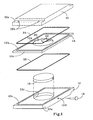
- the watch shown in the drawing has a box of general shape rectangular made from a stack of plates and more particularly provided with two end plates, one upper 10, the other lower 12, and a middle plate 14. It further comprises housed in the box, an assembly comprising a movement 16 provided with a time-setting rod 18 and display means formed by a dial 20 and needles 22.
- the plates 10 and 12 are provided with grooves identified by the letter a extending laterally from one edge to the other of the plate. Recesses identified by the letter b are made in the bottom of the grooves 10a and 12a. The function of the gorges and the hollows will be specified later.
- the lower plate 12 is provided with a recess 12c intended to receive the movement 16.
- a hole 12d connecting one of the lateral faces of the plate 12 to the recess 12c allows the passage of the time-setting rod 18.
- the plate 14 includes a recess 14a pierced in its upper face and the bottom of which forms the dial 20.
- the recesses 12c and 14a define housings intended to receive the assembly formed by movement 16 and display means, the hands 22 being disposed in the recess 14a, while the movement 16 is in drowning 12c.
- the bottom of the recess 14a is, of course, pierced with a hole for connecting the hands to the arranged movement shafts to wear them.
- the plate 14 could be thicker and the recess 14a be arranged to receive movement 16 and the display means, its wall then being drilled with a hole to allow the passage of the setting rod time. It could also be provided with recesses on its two faces, one intended to receive movement 16, the other the needles 22, the wall separating the two recesses in lieu of dial 20.
- the plates 10, 12 and 14 can be made of tempered glass, the plate median 14 advantageously being made of translucent and colored glass for give the box an original appearance.
- seals 24 and 26 are interposed respectively between the plates 10 and 14 on the one hand, 12 and 14 on the other hand. These seals 24 and 26 are housed and positioned respectively in grooves 12e and 14b formed in the upper faces of the plates 12 and 14. It goes without saying that the time-setting rod 18 will also be provided a seal. However, this has not been shown in the drawing.
- the plates are assembled by two identical members 28 (fig 2 and 3), arranged in opposition and each comprising a beam 30 adjoining the lateral faces of the plates 12, 14 and 16 assembled, which form the edge of the box, and two cross members 32 and 34 each fixed to one end of the beam 30 and each forming two arms identified by the letters a and b .
- the arms 32a and 34a extend in abutment against the plates 10 and 12 respectively to apply them against the middle plate 14.
- the beam 30 and the crosspieces 32 and 34 are dimensioned so that their arms 32a and 34a are respectively housed in the grooves 10a and 12a of the plates 10 and 12.
- the arms 32a and 34a include pins identified by the letter c , visible in Figure 2, and which are arranged to engage in the recesses identified by the letter b of the plates 10 and 12, to position them.
- the cross member 32 is fixed to the beam 30 by means of screws 36, while the cross member 34 is permanently fixed to the beam 30 to form together a T-piece
- the box as described is intended to be worn on the wrist by means a bracelet not shown in the drawing, by means of assembly formed of two protrusions 38 in the form of pins permanently fixed in the arm 34b of the cross member 34.
- the pins extend parallel to the beam 30 and slightly beyond.
- the arms 32b are provided non-referenced countersinks in which the ends of the pins 38 are engaged, so as to reinforce the rigidity of the assembly.
- the hollows 10b and 12b could be replaced by holes through plates 10, 12 and 14 right through, and the organs 28 present a symmetry with respect to a plane perpendicular to the plates and arranged in the longitudinal axis of the beam. In this way, the members 28 can be put in place without worry about their orientation. In addition, the plates are positioned in all their thickness.
- the plate stack could have another shape than parallelepiped.
- the assembly members are arranged adjacent to the edge of the box, their shape being adapted for marry.
Landscapes
- Physics & Mathematics (AREA)
- General Physics & Mathematics (AREA)
- Engineering & Computer Science (AREA)
- Manufacturing & Machinery (AREA)
- Electric Clocks (AREA)
Priority Applications (1)
| Application Number | Priority Date | Filing Date | Title |
|---|---|---|---|
| EP03007208A EP1465026A1 (de) | 2003-03-29 | 2003-03-29 | Uhrgehäuse |
Applications Claiming Priority (1)
| Application Number | Priority Date | Filing Date | Title |
|---|---|---|---|
| EP03007208A EP1465026A1 (de) | 2003-03-29 | 2003-03-29 | Uhrgehäuse |
Publications (1)
| Publication Number | Publication Date |
|---|---|
| EP1465026A1 true EP1465026A1 (de) | 2004-10-06 |
Family
ID=32842710
Family Applications (1)
| Application Number | Title | Priority Date | Filing Date |
|---|---|---|---|
| EP03007208A Withdrawn EP1465026A1 (de) | 2003-03-29 | 2003-03-29 | Uhrgehäuse |
Country Status (1)
| Country | Link |
|---|---|
| EP (1) | EP1465026A1 (de) |
Citations (3)
| Publication number | Priority date | Publication date | Assignee | Title |
|---|---|---|---|---|
| EP0131267A1 (de) * | 1983-07-08 | 1985-01-16 | Eta SA Fabriques d'Ebauches | Tragbare Vorrichtung mit sichtbarem Mechanismus |
| WO1998057237A1 (fr) * | 1997-06-12 | 1998-12-17 | Finger Hansjoerg | Boite de montre |
| FR2774486A1 (fr) * | 1998-01-30 | 1999-08-06 | Vuillemin Regnier | Dispositif de maintien liberable de l'extremite d'un bracelet pour boitier de montre a bracelet interchangeable |
-
2003
- 2003-03-29 EP EP03007208A patent/EP1465026A1/de not_active Withdrawn
Patent Citations (3)
| Publication number | Priority date | Publication date | Assignee | Title |
|---|---|---|---|---|
| EP0131267A1 (de) * | 1983-07-08 | 1985-01-16 | Eta SA Fabriques d'Ebauches | Tragbare Vorrichtung mit sichtbarem Mechanismus |
| WO1998057237A1 (fr) * | 1997-06-12 | 1998-12-17 | Finger Hansjoerg | Boite de montre |
| FR2774486A1 (fr) * | 1998-01-30 | 1999-08-06 | Vuillemin Regnier | Dispositif de maintien liberable de l'extremite d'un bracelet pour boitier de montre a bracelet interchangeable |
Similar Documents
| Publication | Publication Date | Title |
|---|---|---|
| EP0098239B1 (de) | Armbanduhr mit einem mittels eines Scharnieres an dem Gehäuse befestigten Band | |
| EP0293948B1 (de) | Schlüsselkopf und Schlüssel mit einem solchen Kopf | |
| FR2509058A1 (fr) | Monture de lunettes a liens souples | |
| EP0770939B1 (de) | Uhr mit einem ein Uhrwerk umfassenden Gehäuse | |
| WO1998014839A1 (fr) | Boite de montre comportant une enveloppe et un dispositif de support | |
| EP3540523B1 (de) | Armbanduhr, die ein uhrengehäuse mit zwei zifferblättern umfasst | |
| EP0541001A1 (de) | Uhrengehäuse mit einem abnehmbaren Boden | |
| CA1051966A (fr) | Piece d'assemblage | |
| EP1680715B1 (de) | Uhr mit umkehrbarem uhrgehäuse | |
| EP0626625B1 (de) | Uhrengehäuse aus Edelmetall | |
| CH696090A5 (fr) | Montre-bracelet à boîtier réversible. | |
| EP1465026A1 (de) | Uhrgehäuse | |
| EP0488918B1 (de) | Halterung- und Positioniersystem für eine Möbelplatte auf ihrem Untersatz | |
| WO1999004306A1 (fr) | Charniere elastique pour branche de lunettes plate | |
| EP1189117B1 (de) | Armbanduhr mit umkehrbarem Gehäuse | |
| EP2032002A1 (de) | Anzeigehalter für armband und armbanduhr | |
| EP1558973B1 (de) | Druckknopfsteuerung, insbesondere für uhrwerk | |
| EP2633775A1 (de) | Armband mit Gelenkgliedern | |
| FR2786884A1 (fr) | Charniere de lunettes | |
| FR2991466A1 (fr) | Monture de lunettes | |
| WO1999053362A1 (fr) | Monture de lunettes modulable | |
| FR3040219B1 (fr) | Montre-bracelet a changement de bracelet facilite | |
| EP1554625A1 (de) | Abschirmung für brillen und komponenten zur herstellung einer solchen abschirmung | |
| EP3404494B1 (de) | Uhrengehäuse | |
| EP1241541A1 (de) | Mittels des Glasreifes zusammengebautes Uhrengehäuse |
Legal Events
| Date | Code | Title | Description |
|---|---|---|---|
| PUAI | Public reference made under article 153(3) epc to a published international application that has entered the european phase |
Free format text: ORIGINAL CODE: 0009012 |
|
| AK | Designated contracting states |
Kind code of ref document: A1 Designated state(s): AT BE BG CH CY CZ DE DK EE ES FI FR GB GR HU IE IT LI LU MC NL PT SE SI SK TR |
|
| AX | Request for extension of the european patent |
Extension state: AL LT LV MK RO |
|
| 17P | Request for examination filed |
Effective date: 20050324 |
|
| AKX | Designation fees paid |
Designated state(s): CH LI |
|
| REG | Reference to a national code |
Ref country code: DE Ref legal event code: 8566 |
|
| RAP1 | Party data changed (applicant data changed or rights of an application transferred) |
Owner name: MONTRES BOEGLI SA |
|
| STAA | Information on the status of an ep patent application or granted ep patent |
Free format text: STATUS: THE APPLICATION IS DEEMED TO BE WITHDRAWN |
|
| 18D | Application deemed to be withdrawn |
Effective date: 20081202 |