EP1464879B1 - Dichtung - Google Patents
Dichtung Download PDFInfo
- Publication number
- EP1464879B1 EP1464879B1 EP04001521A EP04001521A EP1464879B1 EP 1464879 B1 EP1464879 B1 EP 1464879B1 EP 04001521 A EP04001521 A EP 04001521A EP 04001521 A EP04001521 A EP 04001521A EP 1464879 B1 EP1464879 B1 EP 1464879B1
- Authority
- EP
- European Patent Office
- Prior art keywords
- sealing
- sealing body
- seal
- support
- ptfe
- Prior art date
- Legal status (The legal status is an assumption and is not a legal conclusion. Google has not performed a legal analysis and makes no representation as to the accuracy of the status listed.)
- Expired - Lifetime
Links
- 238000007789 sealing Methods 0.000 title claims description 122
- 239000000428 dust Substances 0.000 claims description 7
- 239000000463 material Substances 0.000 claims description 5
- 238000004073 vulcanization Methods 0.000 claims description 5
- 239000004815 dispersion polymer Substances 0.000 claims description 4
- 239000004810 polytetrafluoroethylene Substances 0.000 description 34
- 229920001343 polytetrafluoroethylene Polymers 0.000 description 34
- 229920001971 elastomer Polymers 0.000 description 13
- 239000000806 elastomer Substances 0.000 description 12
- 239000004745 nonwoven fabric Substances 0.000 description 6
- 230000013011 mating Effects 0.000 description 5
- 150000001875 compounds Chemical class 0.000 description 4
- 239000006185 dispersion Substances 0.000 description 4
- 229920000642 polymer Polymers 0.000 description 4
- 230000004913 activation Effects 0.000 description 3
- 229920002635 polyurethane Polymers 0.000 description 3
- 239000004814 polyurethane Substances 0.000 description 3
- 239000000126 substance Substances 0.000 description 3
- 238000010276 construction Methods 0.000 description 2
- 238000001125 extrusion Methods 0.000 description 2
- 239000000835 fiber Substances 0.000 description 2
- 239000004816 latex Substances 0.000 description 2
- 229920000126 latex Polymers 0.000 description 2
- OKTJSMMVPCPJKN-UHFFFAOYSA-N Carbon Chemical compound [C] OKTJSMMVPCPJKN-UHFFFAOYSA-N 0.000 description 1
- 241001295925 Gegenes Species 0.000 description 1
- 229910000831 Steel Inorganic materials 0.000 description 1
- 239000013536 elastomeric material Substances 0.000 description 1
- 239000010439 graphite Substances 0.000 description 1
- 229910002804 graphite Inorganic materials 0.000 description 1
- 230000020169 heat generation Effects 0.000 description 1
- 239000011256 inorganic filler Substances 0.000 description 1
- 229910003475 inorganic filler Inorganic materials 0.000 description 1
- 239000010687 lubricating oil Substances 0.000 description 1
- 238000004519 manufacturing process Methods 0.000 description 1
- 238000000034 method Methods 0.000 description 1
- 239000010445 mica Substances 0.000 description 1
- 229910052618 mica group Inorganic materials 0.000 description 1
- VEOQUPNIEFSTFA-UHFFFAOYSA-J molybdenum(4+) sulfinato sulfite Chemical compound S(=O)([O-])OS(=O)[O-].[Mo+4].S(=O)([O-])OS(=O)[O-] VEOQUPNIEFSTFA-UHFFFAOYSA-J 0.000 description 1
- 229920000728 polyester Polymers 0.000 description 1
- 238000003825 pressing Methods 0.000 description 1
- 230000002787 reinforcement Effects 0.000 description 1
- 230000003014 reinforcing effect Effects 0.000 description 1
- 239000010959 steel Substances 0.000 description 1
- 239000003351 stiffener Substances 0.000 description 1
- 239000000454 talc Substances 0.000 description 1
- 229910052623 talc Inorganic materials 0.000 description 1
- 235000012222 talc Nutrition 0.000 description 1
- 238000003466 welding Methods 0.000 description 1
Images





Classifications
-
- F—MECHANICAL ENGINEERING; LIGHTING; HEATING; WEAPONS; BLASTING
- F16—ENGINEERING ELEMENTS AND UNITS; GENERAL MEASURES FOR PRODUCING AND MAINTAINING EFFECTIVE FUNCTIONING OF MACHINES OR INSTALLATIONS; THERMAL INSULATION IN GENERAL
- F16J—PISTONS; CYLINDERS; SEALINGS
- F16J15/00—Sealings
- F16J15/16—Sealings between relatively-moving surfaces
- F16J15/32—Sealings between relatively-moving surfaces with elastic sealings, e.g. O-rings
- F16J15/3284—Sealings between relatively-moving surfaces with elastic sealings, e.g. O-rings characterised by their structure; Selection of materials
-
- F—MECHANICAL ENGINEERING; LIGHTING; HEATING; WEAPONS; BLASTING
- F16—ENGINEERING ELEMENTS AND UNITS; GENERAL MEASURES FOR PRODUCING AND MAINTAINING EFFECTIVE FUNCTIONING OF MACHINES OR INSTALLATIONS; THERMAL INSULATION IN GENERAL
- F16J—PISTONS; CYLINDERS; SEALINGS
- F16J15/00—Sealings
- F16J15/16—Sealings between relatively-moving surfaces
- F16J15/34—Sealings between relatively-moving surfaces with slip-ring pressed against a more or less radial face on one member
- F16J15/3496—Sealings between relatively-moving surfaces with slip-ring pressed against a more or less radial face on one member use of special materials
Definitions
- the invention relates to a seal for sealing rotating shafts or reciprocating rods, with a shaft or rod sealing sealing body with a sealing surface or sealing edge, wherein the sealing body on its surface facing the shaft or rod with a sealing surface or Sealing edge forming pad is provided from a impregnated with a polymer dispersion nonwoven.
- polymeric materials such as elastomers, polyurethanes or PTFE compounds are generally used.
- the elastomers and the polyurethanes are characterized by excellent elastic properties, combined with optimum adaptability to the mating surface.
- polyurethanes are used for hydraulic and pneumatic seals because of their very good resistance to wear and tear propagation. Nevertheless, high coefficients of friction, low thermal and chemical resistance problems.
- PTFE compounds are characterized by very good sliding properties as well as excellent chemical and thermal resistance out. However, they tend to creep, are hard and do not conform so well to the mating surface.
- elastomers and PTFE are often used together in a sealing system and connected together.
- the elastomer takes over the task of elastic contact pressure of the sealing edge or outsole to the mating surface.
- the sealing edge itself is made of PTFE.
- a sealing edge has the disadvantage of low adaptability in the microscopic range.
- due to the low surface energy of the PTFE compounds a cohesive connection to the elastomer only after elaborate activation of its surface possible, which is associated with high costs and process-related, usually leads to high pollution of the environment.
- a seal is known in which the sealing sleeve consists of a PTFE compound, which is held on a polymeric material. Such a seal is well suited for many applications.
- DD 113 608 Another option is shown in DD 113 608.
- a PTFE support is installed in the area of the sealing lip.
- the pad has a small thickness and is connected to the elastomeric support body by vulcanization or by welding.
- sealing ring has at least two axially spaced adjacent sealing lips, wherein the medium to be sealed facing the first sealing lip made of PTFE. Even with this arrangement can not be avoided that the sealing lip made of PTFE with considerable Pressure on the shaft or piston rod must be pressed and thereby subject to wear and high heat generation.
- US Pat. No. 3,671,048 discloses the possibility of attaching a sealing ring made of felt to a sealing lip made of rubber.
- the invention has for its object to provide an improved seal that is easy to manufacture, has a high mechanical resistance and at the same time has the lowest possible friction.
- the PTFE fleece is inserted into a recess of the sealing body.
- the PTFE nonwoven can be inserted into the recess of the sealing body and are held therein alone form-fitting manner.
- the sealing body is provided at least on one of its surfaces with a support of a nonwoven fabric impregnated with a polymer dispersion.
- the resulting polymer web can be impregnated with a latex, a PTFE, FEP or PFA dispersion.
- a PTFE nonwoven material which consists of at least one impregnated with a PTFE dispersion nonwoven fabric layer.
- the nonwoven fabric layers are made of mechanically bonded nonwoven fabric with fiber lengths of 3 to 100 mm, in particular from 3 to 20 mm and a facilitatorngew. from 20 to 500 g / m 2 .
- the PTFE dispersion is an aqueous dispersion which may contain up to 50% by weight of graphite, talcum, mica or molybdenum disulfite based on the dry mass of PTFE as inorganic filler.
- the support is arranged on the surface of the sealing body facing the outside at a distance from the sealing surface or the sealing edge.
- the seal is formed at lower pressures of the polymeric sealing body itself and only at higher pressures occurs an increased pressing of the polymeric sealing body to the shaft or rod and only then comes the support with the shaft or rod in touch.
- the PTFE fleece is inserted into a recess of the sealing body.
- the PTFE nonwoven can be inserted into the recess of the sealing body and are held therein alone form-fitting manner.
- a radial shaft seal is shown schematically, which consists of a stiffening ring 2 with the elastomer 3 in a conventional manner.
- the seal 1 is fixed in the housing 4.
- the sealing body formed by the elastomer 3 is provided on its outwardly directed surface 6 with the support 7 made of a PTFE fleece.
- the support 7 is provided on the sealing surface 8 in a conventional manner with a structure for returning the lubricating oil in the interior 9.
- FIG. 2 shows a seal in which the sealing body 3 has the sealing edge 9.
- the sealing edge 9 is additionally pressed by the coil spring 10 to the shaft 5.
- the sealing body 3 is provided with a dust lip 11.
- FIG. 3 shows a design of the sealing edge 9 comparable to FIG. 2 in the case of a rod seal.
- the sealing edge 9 is attached to the sealing body 3 and is pressed against the rod 12.
- the sealing body 3 is provided with a support 7, which extends substantially over the entire outside 6 of the surface of the sealing body 3. As a result, a significant stiffening of the entire sealing body 3 is achieved.
- FIG. 5 Another application (not according to the invention) is shown in FIG. 5, in which an existing of a polymer sealing ring 13 is provided with a support 7 which rests against the rod 12. The polymer ring 13 is pressed by the O-ring 14 to the rod 12.
- Fig. 6 shows the application of the support 7 in a mechanical seal not according to the invention.
- the ring 15 is provided with the support 7 which slidably bears against the ring 16.
- the rings 15 and 16 are sealed via the seals 17 and 18 on the housing 4 and on the shaft 5.
- FIG. 7 shows a non-inventive embodiment, in which the support 7 extends substantially over the entire surface 6 of the sealing body 3.
- a sealing edge 9 which is pressed against the shaft 5.
- the sealing body 3 is supported by the spring 10.
- the support 7 acts as a stiffener for the sealing body.
- the sealing edge 9 is formed by the elastomeric sealing body 3 and on the interior 19 of the seal 1 directed surface of the sealing body 3, the support 7 is attached.
- the so arranged support 7 contributes to the stiffening of the sealing body 3 significantly.
- a good seal can be achieved by the sealing lip 9, the wear resistance of course by the use of a support 7 in the region of the sealing lip 9 can be improved.
- Fig. 8 shows a rod seal 1, in which the sealing body 3 is provided with the sealing lip 9 which bears against the rod 12. To reduce the gap extrusion of the sealing body 3, the support 7 is applied as reinforcement on the outwardly directed surface 6 of the sealing body 3.
- a good seal is achieved by the sealing edge 9 made of an elastomer in conjunction with a good protection against wear during the pressurization from the interior 19 of the seal 1.
- the sealing body 3 is provided with the support ring 2 and has a sealing lip 9, which rests directly on the shaft 5. With a small distance 21 from the sealing edge 9, a support 7 is inserted into the sealing body 3, which comes to bear against the shaft 5 only at higher pressures in the interior 19. During operation at lower pressures, the sealing edge 9 made of elastomeric material is pressed against the shaft 5 by the sealing body 3 or additionally by the helical spring 10 against the shaft 5.
- the sealing body 3 bulges in the direction of the shaft 5, so that the support 7 comes to rest on the shaft 5 and causes, despite the higher pressures in the interior 19, the frictional forces and wear between the Sealing body 3 and the shaft 5 relative to the direct seal of the elastomeric sealing edge 9 can be reduced.
- the seal 1 is provided with the sealing lip 22 against dirt, which is also formed from a PTFE non-woven.
- the sealing body 2 is provided with the support 7, which is fastened only with its radially outer end on the sealing body 3.
- the radially inner end of the support 7 rests against the shaft 5 as a sealing surface 8.
- the support 7 is at the radially inner end with the Provided spring element 23 which presses the radially inner end of the shaft 5.
- FIG. 11 shows a non-inventive embodiment of the seal 1, which is provided with a V-shaped in cross-section spring element 24.
- the sealing body 3 is provided on its outwardly directed surface completely with the support 7.
- the cassette seal 1 shown consists of the outer ring of the support ring 2, and the sealing body 3 with sealing edge 9.
- the sealing edge 9 is pressed by the lip 30 of the sealing body 3 to the running surface of the inner ring 25.
- the inner ring 25 is fastened to the shaft 5 via its own sealing body 26.
- the inner ring 25 is provided with the dust lips 27 and 28, which are each provided with a support 7 made of a PTFE fleece.
- the dust lips 27 and 28 slide on the inner surfaces of the support ring 2.
- the sealing body 3 also has a dust lip 29, which can also be equipped with a support 7 if necessary.
- the attachment of the support 7 on the sealing body 3 can be done in various ways. For example, it is possible to insert the support 7 in a corresponding recess of the sealing body 3. Such a recess is shown, for example, in the embodiments according to FIGS. 1, 2, 3, 4, 8, 9, 10 and 12.
- the support 7 is in the recess a form-fitting.
Landscapes
- Engineering & Computer Science (AREA)
- General Engineering & Computer Science (AREA)
- Mechanical Engineering (AREA)
- Sealing With Elastic Sealing Lips (AREA)
- Sealing Devices (AREA)
- Sealing Of Bearings (AREA)
Description
- Die Erfindung befasst sich mit einer Dichtung zum Abdichten von drehenden Wellen oder hin und her bewegten Stangen, mit einem die Welle oder die Stange abdichtenden Dichtkörper mit einer Dichtfläche oder Dichtkante, wobei der Dichtkörper an seiner zur Welle oder Stange gerichteten Oberfläche mit einer die Dichtfläche oder Dichtkante bildenden Auflage aus einem mit einer Polymerdispersion imprägnierten Vlies versehen ist.
- Bei dynamischen Dichtungen sind die Kontaktflächen und die Gegenlaufflächen durch die Relativbewegung thermisch und mechanisch im allgemeinen hochbelastet. Um eine gute Abdichtung zu erreichen, werden in der Regel polymere Werkstoffe wie Elastomere, Polyurethane oder PTFE-Compounds eingesetzt. Dabei zeichnen sich die Elastomere und auch die Polyurethane durch hervorragende elastische Eigenschaften, verbunden mit optimaler Anpassungsfähigkeit an die Gegenlauffläche aus. So werden Polyurethane wegen ihres sehr guten Verschleiß- und Weiterreißwiderstandes für Hydraulik- und Pneumatikdichtungen eingesetzt. Dennoch bereiten hohe Reibwerte, geringe thermische und chemische Beständigkeit Probleme. PTFE-Compounds zeichnen sich durch sehr gute Gleiteigenschaften sowie exzellente chemische und thermische Beständigkeit aus. Sie neigen jedoch zum Kriechen, sind hart und passen sich nicht so gut an die Gegenlauffläche an. Es werden deshalb häufig Elastomere und PTFE zusammen in einem Dichtsystem eingesetzt und miteinander verbunden. Das Elastomer übernimmt die Aufgabe der elastischen Anpressung der Dichtkante oder Laufsohle an die Gegenlauffläche. Die Dichtkante selbst besteht aus PTFE. Eine solche Dichtkante hat jedoch den Nachteil geringer Anpassungsfähigkeit im mikroskopischen Bereich. Auch ist auf Grund der geringen Oberflächenenergie des PTFE-Compounds eine stoffschlüssige Verbindung zum Elastomer nur nach aufwändigem Aktivieren seiner Oberfläche möglich, was mit hohen Kosten verbunden ist und, prozessbedingt, auch meist zu hoher Belastung der Umwelt führt.
- Aus der älteren DE 102 06 624 ist eine Dichtung bekannt, bei der die Dichtmanschette aus einem PTFE-Compound besteht, die an einem polymeren Werkstoff gehalten ist. Eine solche Dichtung ist für viele Anwendungszwecke gut geeignet.
- Eine andere Möglichkeit zeigt die DD 113 608. Dort ist im Bereich der Dichtlippe eine PTFE-Auflage angebracht. Die Auflage hat eine geringe Stärke und ist mit dem elastomeren Tragkörper durch Aufvulkanisieren oder durch eine Verschweißung verbunden.
- Durch die DE 198 39 502 C2 ist außerdem eine Konstruktion bekannt, bei der der Dichtring zumindest zwei mit axialem Abstand zueinander benachbarte Dichtlippen hat, wobei die dem abzudichtenden Medium zugewandte erste Dichtlippe aus PTFE besteht. Auch bei dieser Anordnung lässt sich nicht vermeiden, dass die Dichtlippe aus PTFE mit erheblichem Druck an die Welle bzw. Kolbenstange angepresst werden muss und dadurch einem Verschleiß bei gleichzeitig hoher Wärmeerzeugung unterliegt.
- Aus der ebenfalls älteren DE 101 48 715 A1 ist eine Radialwellendichtung bekannt, bei der ein Dichtelement aus mehreren Vliesstofflagen eingesetzt wird.
- Eine Dichtung, bei der der Dichtkörper mit einer Auflage aus einem mit einer Polymerdispersion imprägnierten Vlies versehen ist, zeigt die GB 1 438 434.
- Auch ist der Einsatz einer Staublippe aus einem ungewebtem Material aus Polyesterfasern, das mit einem Latex imprägniert ist, durch die US 4 306 729 bekannt. Die Staublippe stellt jedoch keinen Dichtkörper an sich dar.
- Schließlich zeigt die US 3 671 048 die Möglichkeit einer Anbringung eines Dichtringes aus Filz an einer aus Gummi bestehenden Dichtlippe.
- Der Erfindung liegt die Aufgabe zugrunde eine verbesserte Dichtung zu erstellen, die leicht herstellbar ist, eine hohe mechanische Beständigkeit hat und gleichzeitig eine möglichst geringe Reibung aufweist.
- Die Lösung der gestellten Aufgabe wird mit den Merkmalen des Anspruchs 1 erreicht. Bei der konstruktiven Ausgestaltung ist es vorteilhaft, wenn das PTFE-Vlies in eine Vertiefung des Dichtkörpers eingefügt wird. Dabei kann das PTFE-Vlies in die Vertiefung des Dichtkörpers eingelegt sein und darin allein formschlüssig gehalten werden. Möglich ist aber auch das PTFE-Vlies mit dem Dichtkörper zu verkleben, beziehungsweise durch Vulkanisation zu verbinden. Der Dichtkörper ist zumindest an einer seiner Oberflächen mit einer Auflage aus einem mit einer Polymerdispersion imprägnierten Vlies versehen ist. Das entstandene Polymervlies kann mit einem Latex, einer PTFE-, FEP- oder PFA-Dispersion imprägniert sein. In Versuchen zeigte sich, dass insbesondere ein mit PTFE imprägniertes Vlies auf vielfältige Weise überraschend gute, nicht vorhersehbare Ergebnisse liefert. So konnten deutlich die Reibungskräfte und der Verschleißwiderstand herabgesetzt werden. Dabei wurde gleichzeitig eine hohe thermische und chemische Beständigkeit in Verbindung mit guter Anpassungsfähigkeit an die Gegenlauffläche erreicht. Auch konnte festgestellt werden, dass bei der Verbindung des PTFE-Vlieses mit dem Dichtkörper auf eine Aktivierung verzichtet werden kann. Auch ohne Aktivierung konnte eine ausreichend feste form- und stoffschlüssige Verbindung erreicht werden.
- Als PTFE-Vlies wird ein Material verwendet, das aus mindestens einer mit einer PTFE-Dispersion imprägnierten Vliesstofflage besteht. In der älteren DE 101 48 715 sind PTFE-Vliese als Dichtelemente bei Radialwellendichtungen bereits beschrieben. Insofern wird auf diese ältere Patentanmeldung Bezug genommen. Die Vliesstofflagen bestehen aus mechanisch gebundenem Vliesstoff mit Faserlängen von 3 bis 100 mm insbesondere von 3 bis 20 mm und einem Flächengew. von 20 bis 500 g/m2. Die PTFE-Dispersion ist eine wässrige Dispersion, welche bis zu 50 Gew.% an Graphit, Talcum, Glimmer oder Molybdändisulfit bezogen auf die Trockenmasse an PTFE als anorganischen Füflstoff enthalten kann.
- Möglich ist aber auch eine Ausbildung, bei der die Auflage auf der zur Außenseite gerichteten Oberfläche des Dichtkörpers mit Abstand zur Dichtfläche oder zur Dichtkante angeordnet ist. Bei dieser Ausführungsform wird die Dichtung bei geringeren Drücken von dem polymeren Dichtkörper selbst gebildet und erst bei höheren Drücken erfolgt ein verstärktes Andrücken des polymeren Dichtkörpers an die Welle beziehungsweise Stange und erst dann kommt die Auflage mit der Welle beziehungsweise Stange in Berührung.
- Neben der Ausstattung des Dichtkörpers mit der Auflage aus einem PTFE-Vlies zu Dichtungs- beziehungsweise Versteifungszwecken ist es auch möglich, ergänzend hierzu die Dichtung mit einer Schmutz-Dichtlippe aus einem PTFE-Vlies zu versehen.
- Bei der konstruktiven Ausgestaltung ist es vorteilhaft, wenn das PTFE-Vlies in eine Vertiefung des Dichtkörpers eingefügt wird. Dabei kann das PTFE-Vlies in die Vertiefung des Dichtkörpers eingelegt sein und darin allein formschlüssig gehalten werden. Möglich ist aber auch das PTFE-Vlies mit dem Dichtkörper zu verkleben, beziehungsweise durch Vulkanisation zu verbinden.
- In der beiliegenden Zeichnung sind mehrere Ausführungsbeispiele der Erfindung in schematischer Darstellung wiedergegeben.
- Es zeigt:
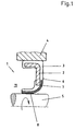
- Fig. 1
- einen Längsschnitt durch die Dichtung mit einer an der Welle anliegenden Dichtfläche,
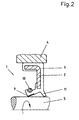
- Fig. 2
- eine Dichtung mit einer an der Welle anliegenden Dichtkante,
- Fig. 3
- eine Stangendichtung mit einer Dichtkante,
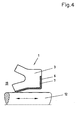
- Fig. 4
- eine Stangendichtung mit einer Dichtkante und einer Versteifung des Dichtkörpers,
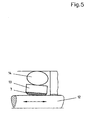
- Fig. 5
- eine nicht erfindungsgemäße Stangendichtung mit einem O-Ring als Sekundärdichtung und Vorspannelement,
- Fig. 6
- die Anwendung der Auflage bei einer nicht erfindugsgemäßen Gleitringdichtung
- Fig. 7.
- eine nicht erfindungsgemäße Wellendichtung mit einem PTFE-Vlies als Dichtkante und als Versteifungsauflage;
- Fig. 8
- eine Stangendichtung mit einer auf der zur Außenseite gerichteten Oberfläche des Dichtkörpers angebrachten Verstärkungsauflage;
- Fig. 9
- einen Schnitt durch eine Wellendichtung mit zur Dichtkante versetzt angeordneten Auflage aus einem PTFE-Vlies und einer Dichtlippe gegen Schmutz aus einem PTFE -Vlies;
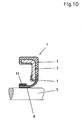
- Fig. 10
- eine Wellendichtung mit einem Federelement aus einem Elastomer,
- Fig. 11
- eine nicht erfindungsgemäße Dichtung mit einem PTFE Vlies und einer Stahlfeder und
- Fig. 12
- die Anwendung des Erfindungsgedankens bei einer Kassettendichtung.
- In der Fig. 1 ist schematisch eine Radialwellendichtung gezeigt, die in an sich bekannter Weise aus einem Versteifungsring 2 mit dem Elastomer 3 besteht. Über das Elastomer 3 wird die Dichtung 1 in dem Gehäuse 4 befestigt. An dem zur Welle 5 gerichteten Teil des Elastomers 3 ist der von dem Elastomer 3 gebildete Dichtkörper an seiner nach außen gerichteten Oberfläche 6 mit der Auflage 7 aus einem PTFE Vlies versehen. Die Auflage 7 ist an der Dichtfläche 8 in an sich bekannter Weise mit einer Struktur zur Rückführung des Schmieröls in den Innenraum 9 versehen.
- In der Fig. 2 ist eine Dichtung gezeigt, bei der der Dichtkörper 3 die Dichtkante 9 hat. Die Dichtkante 9 wird von der Schraubenfeder 10 zusätzlich an die Welle 5 angepresst. Darüber hinaus ist der Dichtkörper 3 mit einer Staublippe 11 versehen.
- Die Fig. 3 zeigt eine mit der Fig. 2 vergleichbare Ausbildung der Dichtkante 9 bei einer Stangendichtung. Die Dichtkante 9 ist am Dichtkörper 3 angebracht und wird an die Stange 12 angedrückt.
- Bei der Ausführungsform nach der Fig. 4 ist der Dichtkörper 3 mit einer Auflage 7 versehen, welche sich im Wesentlichen über die gesamte Außenseite 6 der Oberfläche des Dichtkörpers 3 erstreckt. Hierdurch wird eine erhebliche Versteifung des gesamten Dichtkörpers 3 erreicht.
- Insbesondere bei hohen Innendrücken im Innenraum 19 ist eine solche Dichtung von Vorteil, da die Auflage einen zusätzlichen Schutz gegen Spaltextrusion darstellt.
- Eine andere Anwendungsmöglichkeit (nicht erfindungsgemäße) zeigt die Fig. 5, bei der ein aus einem Polymer bestehender Dichtring 13 mit einer Auflage 7 versehen ist, welcher an der Stange 12 anliegt. Der Polymerring 13 wird von dem O-Ring 14 an die Stange 12 angedrückt.
- Die Fig. 6 zeigt die Anwendung der Auflage 7 bei einer nicht erfindungsgemäßen Gleitringdichtung. Hierbei ist der Ring 15 mit der Auflage 7 versehen, welche an dem Ring 16 gleitend anliegt. Die Ringe 15 und 16 sind über die Dichtungen 17 und 18 am Gehäuse 4 beziehungsweise an der Welle 5 abgedichtet.
- Die Fig. 7 zeigt eine nicht erfindungsgemäße Ausführungsform, bei der die Auflage 7 sich im Wesentlichen über die gesamte Oberfläche 6 des Dichtkörpers 3 erstreckt. Vorgesehen ist eine Dichtkante 9, welche an die Welle 5 gedrückt wird. Hierbei wird der Dichtkörper 3 durch die Feder 10 unterstützt. Bei der auf der Innenseite 19 der Dichtung 1 vorhandenem höheren Druck wirkt die Auflage 7 als Versteifung für den Dichtkörper 3.
- Eine andere Möglichkeit der Versteifung des Dichtkörpers 3 kann dadurch erreicht werden, dass die Dichtkante 9 von dem elastomeren Dichtkörper 3 gebildet wird und auf der zum Inneren 19 der Dichtung 1 gerichteten Oberfläche des Dichtkörpers 3 die Auflage 7 angebracht wird. Die so angeordnete Auflage 7 trägt zur Versteifung des Dichtkörpers 3 erheblich bei. Dadurch kann auch eine gute Abdichtung durch die Dichtlippe 9 erreicht werden, deren Verschleißfestigkeit natürlich durch den Einsatz einer Auflage 7 im Bereich der Dichtlippe 9 noch verbessert werden kann.
- Die Fig. 8 zeigt eine Stangendichtung 1, bei der der Dichtkörper 3 mit der Dichtlippe 9 versehen ist, die an der Stange 12 anliegt. Zur Verringerung der Spaltextrusion des Dichtkörpers 3 ist auf der nach außen gerichteten Oberfläche 6 des Dichtkörpers 3 die Auflage 7 als Verstärkung aufgebracht.
- Durch die in der Fig. 9 gezeigte Ausführungsform der Dichtung 1 wird eine gute Abdichtung durch die Dichtkante 9 aus einem Elastomer in Verbindung mit einem guten Verschleißschutz bei der Druckbeaufschlagung aus dem Innenraum 19 der Dichtung 1 erzielt. Der Dichtkörper 3 ist mit dem Stützring 2 versehen und hat eine Dichtlippe 9, die direkt an der Welle 5 anliegt. Mit einem geringen Abstand 21 von der Dichtkante 9 ist in den Dichtkörper 3 eine Auflage 7 eingefügt, die erst bei höheren Drücken im Innenraum 19 zur Anlage an der Welle 5 kommt. Im Betrieb mit niedrigeren Drücken wird die Dichtkante 9 aus elastomerem Material an die Welle 5 durch den Dichtkörper 3 beziehungsweise zusätzlich durch die Wendelfeder 10 an die Welle 5 angedrückt. Bei höheren Drücken im Innenraum 19 wölbt sich der Dichtkörper 3 in Richtung auf die Welle 5 aus, so dass die Auflage 7 an der Welle 5 zur Anlage kommt und dazu führt, dass trotz der höheren Drücke im Innenraum 19 die Reibungskräfte und der Verschleiß zwischen dem Dichtkörper 3 und der Welle 5 gegenüber der direkten Dichtung aus der elastomeren Dichtkante 9 verringert werden. Im gezeigten Beispiel ist die Dichtung 1 mit der Dichtlippe 22 gegen Schmutz versehen, die ebenfalls aus einem PTFE-Vlies gebildet ist.
- Bei der Konstruktion nach der Fig. 10 ist der Dichtkörper 2 mit der Auflage 7 versehen, die nur mit ihrem radial äußeren Ende am Dichtkörper 3 befestigt ist. Das radial innenliegende Ende der Auflage 7 liegt als Dichtfläche 8 an der Welle 5 an. Um trotz der teilweise nicht vorhandenen Unterstützung der Auflage 7 durch den Dichtkörper 3 eine sichere Abdichtung an der Welle zu erreichen, ist die Auflage 7 an dem radial inneren Ende mit dem Federelement 23 versehen, welches das radial innere Ende an die Welle 5 anpresst.
- Die Fig. 11 zeigt eine nicht erfindungsgesmäße Ausführungsform der Dichtung 1, die mit einem im Querschnitt gesehen V-förmigen Federelement 24 versehen ist. Der Dichtkörper 3 ist auf seiner nach außen gerichteten Oberfläche vollständig mit der Auflage 7 versehen.
- Eine sehr vorteilhafte Anwendung der Dichtung 1 ist bei einer Kassettendichtung gegeben, wie sie in der Fig. 12 dargestellt ist. Die gezeigte Kassettendichtung 1 besteht aus dem Außenring aus Stützring 2, und dem Dichtkörper 3 mit Dichtkante 9. Die Dichtkante 9 wird durch die Lippe 30 des Dichtkörpers 3 an die Lauffläche des Innenrings 25 angedrückt. Der Innenring 25 wird über einen eigenen Dichtkörper 26 an der Welle 5 befestigt. Der Innenring 25 ist mit den Staublippen 27 und 28 versehen, die jeweils mit einer Auflage 7 aus einem PTFE-Vlies versehen sind. Die Staublippen 27 und 28 gleiten auf den innenliegenden Flächen des Stützrings 2. Zusätzlich hierzu hat der Dichtkörper 3 ebenfalls noch eine Staublippe 29, die bei Bedarf ebenfalls mit einer Auflage 7 ausgerüstet werden kann.
- Die Befestigung der Auflage 7 am Dichtkörper 3 kann auf verschiedene Weise erfolgen. So ist es beispielsweise möglich, die Auflage 7 in eine entsprechende Vertiefung des Dichtkörpers 3 einzulegen. Eine solche Vertiefung ist beispielsweise in den Ausführungsformen nach den Fig. 1, 2, 3, 4, 8, 9, 10 und 12 gezeigt. Die Auflage 7 liegt in der Vertiefung formschlüssig ein. Möglich ist aber auch eine Verbindung der Auflage 7 mit dem Dichtkörper 3 durch Vulkanisation oder Verkleben.
Claims (5)
- Dichtung (1) zum Abdichten von drehenden Wellen (5) oder hin und her bewegten Stangen (12) mit einem die Welle (5) oder die Stange (12) abdichtenden Dichtkörper (3) mit einer Dichtfläche oder Dichtkante, wobei der Dichtkörper (3) an seiner zur Welle (5) oder Stange (12) gerichteten Oberfläche (6) mit einer die Dichtfläche (8) oder Dichtkante (9) bildenden Auflage (7) aus einem mit einer Polymerdispersion imprägnierten Vlies versehen ist, dadurch gekennzeichnet, dass das Vlies in eine Vertiefung des Dichtkörpers (3) eingefügt und darin formschlüssig gehalten ist.
- Dichtung nach Anspruch 1, dadurch gekennzeichnet, dass das Vlies mit dem Dichtkörper (3) verklebt oder durch Vulkanisation verbunden ist.
- Dichtung nach Anspruch 1 bis 2, dadurch gekennzeichnet, dass das Vlies aus mindestens einer, mit einer Polymerdispersion imprägnierten Vliesstofflage besteht.
- Dichtung nach einem der Ansprüche 1 bis 3, dadurch gekennzeichnet, dass die Auflage (7) auf der zur Außenseite gerichteten Oberfläche (6) des Dichtkörpers (3) mit Abstand (21) zur Dichtfläche (8) oder Dichtkante (9) angeordnet ist.
- Dichtung nach einem der Ansprüche 1 bis 4, dadurch gekennzeichnet, dass das Vlies auf der beziehungsweise den Staublippen (27, 28) der Dichtung (1) aufgelegt ist.
Applications Claiming Priority (2)
| Application Number | Priority Date | Filing Date | Title |
|---|---|---|---|
| DE10315333 | 2003-04-03 | ||
| DE10315333A DE10315333B4 (de) | 2003-04-03 | 2003-04-03 | Dichtung |
Publications (2)
| Publication Number | Publication Date |
|---|---|
| EP1464879A1 EP1464879A1 (de) | 2004-10-06 |
| EP1464879B1 true EP1464879B1 (de) | 2006-04-19 |
Family
ID=32842246
Family Applications (1)
| Application Number | Title | Priority Date | Filing Date |
|---|---|---|---|
| EP04001521A Expired - Lifetime EP1464879B1 (de) | 2003-04-03 | 2004-01-24 | Dichtung |
Country Status (7)
| Country | Link |
|---|---|
| US (1) | US20040245729A1 (de) |
| EP (1) | EP1464879B1 (de) |
| JP (1) | JP2004308906A (de) |
| BR (1) | BRPI0400924A (de) |
| CA (1) | CA2460974A1 (de) |
| DE (2) | DE10315333B4 (de) |
| MX (1) | MXPA04003110A (de) |
Families Citing this family (23)
| Publication number | Priority date | Publication date | Assignee | Title |
|---|---|---|---|---|
| JP2005299808A (ja) * | 2004-04-13 | 2005-10-27 | Nok Corp | ポンプ用シール |
| DE202006020585U1 (de) * | 2006-05-03 | 2009-04-02 | Riffel, Roland | Schallabsorbierende Bauelemente und Lärmschutzwand aus schallabsorbierenden Bauelementen |
| FR2910944B1 (fr) * | 2006-12-29 | 2009-02-20 | Snr Roulements Sa | Butee de suspension a roulement, cage de roulement et garniture d'etancheite |
| PT2031252E (pt) * | 2007-08-28 | 2010-05-17 | Ebm Papst Mulfingen Gmbh & Co | Ventilador para o transporte de meios |
| US8343370B2 (en) | 2009-02-19 | 2013-01-01 | Federal-Mogul Corporation | Method of fabricating a PTFE seal element and a shaft seal assembly therewith |
| US9746081B2 (en) * | 2009-08-25 | 2017-08-29 | Freudenberg-Nok General Partnership | Low load offset seal |
| WO2011079905A1 (en) * | 2009-12-21 | 2011-07-07 | Aktiebolaget Skf (Publ) | Method and device of a sealing system |
| DE102010001345B4 (de) * | 2010-01-28 | 2013-09-19 | Trelleborg Sealing Solutions Germany Gmbh | Drehdurchführung |
| JP5746934B2 (ja) * | 2011-08-31 | 2015-07-08 | 電気化学工業株式会社 | ローラー及びコンベア装置 |
| US9285121B2 (en) | 2012-08-23 | 2016-03-15 | General Electric Company | Gas turbine cooling circuit including a seal for a perforated plate |
| US9562689B2 (en) | 2012-08-23 | 2017-02-07 | General Electric Company | Seal for fuel distribution plate |
| JP5955765B2 (ja) * | 2012-12-27 | 2016-07-20 | 三菱電機ビルテクノサービス株式会社 | エレベータドア気密装置およびその製造方法 |
| PL2815158T3 (pl) * | 2013-04-22 | 2016-03-31 | Freudenberg Carl Kg | Przesuwne uszczelnienie pierścieniowe |
| WO2014173425A1 (en) | 2013-04-22 | 2014-10-30 | Carl Freudenberg Kg | Slide ring seal |
| WO2014173495A2 (de) * | 2013-04-22 | 2014-10-30 | Carl Freudenberg Kg | Gleitringdichtung |
| DE102014107107A1 (de) | 2014-05-20 | 2015-11-26 | Elringklinger Ag | Dichtungsvorrichtung |
| US10316604B2 (en) * | 2014-07-02 | 2019-06-11 | Utex Industries, Inc. | Inflatable seal with fabric expansion restriction |
| DE102014010269B4 (de) * | 2014-07-11 | 2020-06-18 | Carl Freudenberg Kg | Vorschaltdichtung, Vorschaltdichtungsanordnung und Dichtring, umfassend die Vorschaltdichtung |
| US10215286B2 (en) | 2014-09-11 | 2019-02-26 | Aktiebolaget Skf | Dynamic seal |
| DE102017004061B4 (de) * | 2017-04-27 | 2019-01-31 | Carl Freudenberg Kg | Dichtung |
| DE102021001799A1 (de) * | 2021-04-06 | 2022-10-06 | Kaco Gmbh + Co. Kg | Funktionselement, insbesondere Dichtung, und Verfahren zur Herstellung des Grundmaterials des Funktionselementes |
| DE102021113901A1 (de) * | 2021-05-28 | 2022-12-01 | Carl Freudenberg Kg | Anordnung zur Herstellung einer elektrisch leitfähigen Verbindung zwischen einem ersten Maschinenelement und einem zweiten Maschinenelement |
| DE102022000620A1 (de) * | 2022-02-17 | 2023-08-17 | Kaco Gmbh + Co. Kg | Dichtungsanordnung, insbesondere Gleitringdichtung, vorzugsweise für den Einsatz in Kühlmittelaggregaten |
Family Cites Families (13)
| Publication number | Priority date | Publication date | Assignee | Title |
|---|---|---|---|---|
| US3671048A (en) * | 1970-06-12 | 1972-06-20 | Borg Warner | Lip type seal |
| AT328815B (de) * | 1973-07-25 | 1976-04-12 | Simmerwerke Simmer Kg | Einbaufertige elastisch-verformbare dichtung und verfahren zu deren herstellung |
| IT1016411B (it) * | 1973-08-03 | 1977-05-30 | Freudenberg C | Perfezionamenti nelle guarnizioni di tenuta in particolare per alberi rotanti |
| US4306729A (en) * | 1979-09-26 | 1981-12-22 | Nippon Oil Seal Industry Co., Ltd. | Sealing material |
| DE3212476C1 (de) * | 1982-04-03 | 1983-11-17 | Goetze Ag, 5093 Burscheid | Wellendichtring |
| DE4423043C2 (de) * | 1994-07-01 | 2000-09-07 | Inst Textil & Verfahrenstech | Stopfbuchspackung |
| US6401322B1 (en) * | 1996-03-25 | 2002-06-11 | Nok Corporation | Method of manufacturing a sealing apparatus |
| JP3860283B2 (ja) * | 1996-06-26 | 2006-12-20 | Nok株式会社 | 密封装置 |
| DE19839502C2 (de) * | 1998-08-29 | 2001-06-07 | Freudenberg Carl Fa | Dichtring |
| US6367811B1 (en) * | 1998-11-24 | 2002-04-09 | Mitsubishi Cable Industries, Ltd. | Rotation shaft seal |
| DE10206624A1 (de) * | 2001-03-27 | 2003-05-22 | Freudenberg Carl Kg | Dichtring |
| DE10122094B4 (de) * | 2001-05-07 | 2006-04-27 | Carl Freudenberg Kg | Stopfbuchspackung aus einem Dichtelement und Verfahren zu seiner Herstellung |
| DE10148715B4 (de) * | 2001-10-02 | 2007-10-25 | Carl Freudenberg Kg | Radialwellendichtung und Verfahren zu ihrer Herstellung |
-
2003
- 2003-04-03 DE DE10315333A patent/DE10315333B4/de not_active Expired - Fee Related
-
2004
- 2004-01-24 DE DE502004000433T patent/DE502004000433D1/de not_active Expired - Lifetime
- 2004-01-24 EP EP04001521A patent/EP1464879B1/de not_active Expired - Lifetime
- 2004-03-16 CA CA002460974A patent/CA2460974A1/en not_active Abandoned
- 2004-03-17 US US10/802,674 patent/US20040245729A1/en not_active Abandoned
- 2004-03-31 JP JP2004104401A patent/JP2004308906A/ja active Pending
- 2004-04-01 BR BR0400924-0A patent/BRPI0400924A/pt not_active Application Discontinuation
- 2004-04-01 MX MXPA04003110A patent/MXPA04003110A/es unknown
Also Published As
| Publication number | Publication date |
|---|---|
| DE502004000433D1 (de) | 2006-05-24 |
| US20040245729A1 (en) | 2004-12-09 |
| DE10315333B4 (de) | 2005-10-27 |
| DE10315333A1 (de) | 2004-11-18 |
| CA2460974A1 (en) | 2004-10-03 |
| JP2004308906A (ja) | 2004-11-04 |
| MXPA04003110A (es) | 2004-10-06 |
| EP1464879A1 (de) | 2004-10-06 |
| BRPI0400924A (pt) | 2005-01-11 |
Similar Documents
| Publication | Publication Date | Title |
|---|---|---|
| DE10315333B4 (de) | Dichtung | |
| DE4129370A1 (de) | Hydraulisch betaetigbarer ausruecker mit stuetzring und stuetzschulter | |
| EP3030813B1 (de) | Dichtungssatz sowie dichtungsanordnung mit zumindest einem dichtungssatz | |
| EP0557579A1 (de) | Dichtungsanordnung | |
| WO2013020532A1 (de) | Nehmerzylinder | |
| EP2926024A1 (de) | Verschlusspaket zum verschliessen eines dämpferrohres für einen schwingungsdämpfer | |
| EP1249648B1 (de) | Radialwellendichtring | |
| DE10305173B4 (de) | Dichtring und Dichtungsanordnung, umfassend zwei solcher Dichtringe | |
| EP2827026B1 (de) | Dichtungsanordnung und Dichtring | |
| WO2017198854A1 (de) | Rotationsdichtungsanordnung mit druckaktivierbarer rotationsdichtung sowie rotationsdichtung | |
| DE102014208089A1 (de) | Hybriddichtung für einen Kupplungsnehmerzylinder | |
| EP3299682A1 (de) | Dichtring und dessen verwendung | |
| WO2009030298A1 (de) | Dichtungselement, insbesondere sekundärdichtungselement einer gleitringdichtung | |
| DE102020105149B3 (de) | Dichtring und dessen Verwendung | |
| DE19930964A1 (de) | Radial bewegliche Kolbenstangendichtung | |
| DE3247116C2 (de) | Geberzylinder | |
| DE10113442C2 (de) | Lageranordnung für ein Wellenlager | |
| DE10112453C2 (de) | Kardanwellenlager | |
| EP1612448A1 (de) | Elastomeres Buchsenlager mit verbessertem Torsionsverhalten | |
| WO2014108122A1 (de) | Dichtung für eine hydraulische kolben-zylinder-anordnung | |
| EP3339694B1 (de) | Dichtring eines translatorisch verstellbaren bauelements | |
| EP1288537B1 (de) | Dichtring | |
| DE69709589T2 (de) | Deckel aus Stahlblech für eine rotierende Abdichtung für eine Antriebswelle eines Kraftfahrzeuges | |
| DE102017004480B4 (de) | Dichtring und Dichtungsanordnung, die den Dichtring umfasst | |
| WO2023156486A1 (de) | Dichtungsanordnung, insbesondere gleitringdichtung, vorzugsweise für den einsatz in kühlmittelaggregaten |
Legal Events
| Date | Code | Title | Description |
|---|---|---|---|
| PUAI | Public reference made under article 153(3) epc to a published international application that has entered the european phase |
Free format text: ORIGINAL CODE: 0009012 |
|
| 17P | Request for examination filed |
Effective date: 20040722 |
|
| AK | Designated contracting states |
Kind code of ref document: A1 Designated state(s): AT BE BG CH CY CZ DE DK EE ES FI FR GB GR HU IE IT LI LU MC NL PT RO SE SI SK TR |
|
| AX | Request for extension of the european patent |
Extension state: AL LT LV MK |
|
| 17Q | First examination report despatched |
Effective date: 20050119 |
|
| AKX | Designation fees paid |
Designated state(s): DE FR GB IT |
|
| GRAP | Despatch of communication of intention to grant a patent |
Free format text: ORIGINAL CODE: EPIDOSNIGR1 |
|
| GRAS | Grant fee paid |
Free format text: ORIGINAL CODE: EPIDOSNIGR3 |
|
| GRAA | (expected) grant |
Free format text: ORIGINAL CODE: 0009210 |
|
| AK | Designated contracting states |
Kind code of ref document: B1 Designated state(s): DE FR GB IT |
|
| PG25 | Lapsed in a contracting state [announced via postgrant information from national office to epo] |
Ref country code: IT Free format text: LAPSE BECAUSE OF FAILURE TO SUBMIT A TRANSLATION OF THE DESCRIPTION OR TO PAY THE FEE WITHIN THE PRESCRIBED TIME-LIMIT;WARNING: LAPSES OF ITALIAN PATENTS WITH EFFECTIVE DATE BEFORE 2007 MAY HAVE OCCURRED AT ANY TIME BEFORE 2007. THE CORRECT EFFECTIVE DATE MAY BE DIFFERENT FROM THE ONE RECORDED. Effective date: 20060419 Ref country code: GB Free format text: LAPSE BECAUSE OF FAILURE TO SUBMIT A TRANSLATION OF THE DESCRIPTION OR TO PAY THE FEE WITHIN THE PRESCRIBED TIME-LIMIT Effective date: 20060419 |
|
| REG | Reference to a national code |
Ref country code: GB Ref legal event code: FG4D Free format text: NOT ENGLISH |
|
| REF | Corresponds to: |
Ref document number: 502004000433 Country of ref document: DE Date of ref document: 20060524 Kind code of ref document: P |
|
| ET | Fr: translation filed | ||
| GBV | Gb: ep patent (uk) treated as always having been void in accordance with gb section 77(7)/1977 [no translation filed] |
Effective date: 20060419 |
|
| PLBE | No opposition filed within time limit |
Free format text: ORIGINAL CODE: 0009261 |
|
| STAA | Information on the status of an ep patent application or granted ep patent |
Free format text: STATUS: NO OPPOSITION FILED WITHIN TIME LIMIT |
|
| 26N | No opposition filed |
Effective date: 20070122 |
|
| PGFP | Annual fee paid to national office [announced via postgrant information from national office to epo] |
Ref country code: FR Payment date: 20120202 Year of fee payment: 9 |
|
| PGFP | Annual fee paid to national office [announced via postgrant information from national office to epo] |
Ref country code: DE Payment date: 20120207 Year of fee payment: 9 |
|
| PGFP | Annual fee paid to national office [announced via postgrant information from national office to epo] |
Ref country code: IT Payment date: 20120119 Year of fee payment: 9 |
|
| REG | Reference to a national code |
Ref country code: FR Ref legal event code: ST Effective date: 20130930 |
|
| PG25 | Lapsed in a contracting state [announced via postgrant information from national office to epo] |
Ref country code: DE Free format text: LAPSE BECAUSE OF NON-PAYMENT OF DUE FEES Effective date: 20130801 |
|
| REG | Reference to a national code |
Ref country code: DE Ref legal event code: R119 Ref document number: 502004000433 Country of ref document: DE Effective date: 20130801 |
|
| PG25 | Lapsed in a contracting state [announced via postgrant information from national office to epo] |
Ref country code: FR Free format text: LAPSE BECAUSE OF NON-PAYMENT OF DUE FEES Effective date: 20130131 |
|
| PG25 | Lapsed in a contracting state [announced via postgrant information from national office to epo] |
Ref country code: IT Free format text: LAPSE BECAUSE OF NON-PAYMENT OF DUE FEES Effective date: 20130124 |