EP1464795A2 - Elektrischer Ventiltrieb für Verbrennungsmotoren mit Ventilspieldämpfungselement - Google Patents
Elektrischer Ventiltrieb für Verbrennungsmotoren mit Ventilspieldämpfungselement Download PDFInfo
- Publication number
- EP1464795A2 EP1464795A2 EP04005096A EP04005096A EP1464795A2 EP 1464795 A2 EP1464795 A2 EP 1464795A2 EP 04005096 A EP04005096 A EP 04005096A EP 04005096 A EP04005096 A EP 04005096A EP 1464795 A2 EP1464795 A2 EP 1464795A2
- Authority
- EP
- European Patent Office
- Prior art keywords
- valve
- fluid
- electrically controllable
- actuator
- actuator element
- Prior art date
- Legal status (The legal status is an assumption and is not a legal conclusion. Google has not performed a legal analysis and makes no representation as to the accuracy of the status listed.)
- Withdrawn
Links
- 238000002485 combustion reaction Methods 0.000 title claims abstract description 5
- 239000012530 fluid Substances 0.000 claims abstract description 32
- 238000013016 damping Methods 0.000 claims abstract description 18
- 238000006073 displacement reaction Methods 0.000 claims description 2
- 125000006850 spacer group Chemical group 0.000 description 6
- 238000004519 manufacturing process Methods 0.000 description 3
- 238000011161 development Methods 0.000 description 1
- 230000018109 developmental process Effects 0.000 description 1
- 238000005265 energy consumption Methods 0.000 description 1
Images


Classifications
-
- F—MECHANICAL ENGINEERING; LIGHTING; HEATING; WEAPONS; BLASTING
- F01—MACHINES OR ENGINES IN GENERAL; ENGINE PLANTS IN GENERAL; STEAM ENGINES
- F01L—CYCLICALLY OPERATING VALVES FOR MACHINES OR ENGINES
- F01L9/00—Valve-gear or valve arrangements actuated non-mechanically
- F01L9/20—Valve-gear or valve arrangements actuated non-mechanically by electric means
-
- F—MECHANICAL ENGINEERING; LIGHTING; HEATING; WEAPONS; BLASTING
- F01—MACHINES OR ENGINES IN GENERAL; ENGINE PLANTS IN GENERAL; STEAM ENGINES
- F01L—CYCLICALLY OPERATING VALVES FOR MACHINES OR ENGINES
- F01L9/00—Valve-gear or valve arrangements actuated non-mechanically
- F01L9/20—Valve-gear or valve arrangements actuated non-mechanically by electric means
- F01L9/21—Valve-gear or valve arrangements actuated non-mechanically by electric means actuated by solenoids
- F01L2009/2132—Biasing means
- F01L2009/2134—Helical springs
- F01L2009/2136—Two opposed springs for intermediate resting position of the armature
Definitions
- the present invention relates to an electrically controllable valve train according to the preamble of claim 1.
- valve train controls are being tested.
- the valves by an electromagnetically actuated actuator element or by a actuated by an electric motor actuated element.
- it speaks one of stroke actuators
- the actuator element presses the valve against the force of one or several valve springs in the direction of the combustion chamber.
- the valve For a flawless Operation requires the valve to be in relation to the actuator element has a certain valve clearance.
- Spacer for example a cap, on the free end of the Valve stem.
- the actuator element When the valve is opened, the actuator element hits the end without being braked of the valve stem or on that arranged at the end of the valve stem Spacer on. On the one hand, this creates a loud impact noise, that negatively affects the entire engine acoustics. On the other hand the valve is vibrated strongly, which regulates the Valve train extremely difficult.
- the object of the invention is to provide an electrically controllable valve train create that in terms of noise and emergence mechanical vibrations is optimized.
- the present invention is based on an electrically controllable valve train for internal combustion engines.
- an electrically controllable actuator element is provided to move the valve, that is to say When the valve is opened.
- the actuator element can be a stroke actuator, for example, the one anchor plate slidably arranged between two electromagnets and has an anchor shaft.
- the anchor shaft exercises to open the Valve exerts a force on the valve stem.
- the essence of the invention is a hydraulic damping element, which is arranged between the valve stem and the actuator element.
- the damping element has two fluid volumes. When opening the Valve through the actuator element must first the valve clearance be overcome. In this case, fluid is removed from the via a "throttle point" one fluid volume pressed into the other fluid volume.
- the actuator element thus does not hit the end of the valve stem without braking or on the spacer element arranged at the end of the valve stem on, but sets, due to the damping element comparatively "gently” on. This will both the "impact noise” mentioned above as well as the mechanical vibration caused by the impact of the valve almost completely avoided. By eliminating the Valve vibration improves the controllability of the valve train.
- the damping element preferably has a cup-shaped or cylindrical cavity through which the first fluid volume is formed and a groove-like cavity in the wall area of the pot-shaped cavity, through which the second fluid volume is formed.
- a free end section of the Actuator element protrudes into the cup-shaped cavity and acts as a displacement piston acts for the fluid contained therein.
- the end section of the actuator element and the cup-shaped cavity form a clearance fit.
- the game fit thus represents a "throttle point" for the transfer of the fluid from the first fluid volume into the second fluid volume.
- the damping element is preferably form-fitting by means of two clamping pieces connected to the free end of the valve stem.
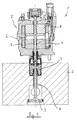
- FIG. 1 shows an electrically controllable valve train 1 with one in one Cylinder head 2 arranged valve 3, which has a valve stem 4.
- the Valve 3 is closed by a valve spring 5 in the shown here Position pressed.
- a Stroke actuator arrangement 2 ' is provided, which essentially consists of a Actuator or anchor element consists of an anchor plate 6 and one with it connected anchor shaft 7.
- the actuator element is axially displaceable arranged between two electromagnets 8, 9, with which the Actuator element can be moved axially.
- the shaft 7 exercises a counteracting action of the valve spring 5 Force on the valve stem 4, which means an opening of the valve 3rd has the consequence.
- valve 3 is in the closed state a certain valve clearance with respect to the actuator element is required.
- a cap-like spacer 10 is applied become. By placing such a spacer 10 with a suitable one Thickness on the end of the valve stem 4 can be a certain one Valve clearance s are observed.
- the damping element 11 is fastened to the end of the valve stem 4 by means of two half-shell-like clamping pieces 12.
- the damping element 11 has a cup-shaped cavity 13 which forms a first fluid volume.
- a second fluid volume formed by an annular groove 14 is provided in the wall area of the damping element 11.
- the free end of the armature shaft 7 protrudes slightly into the cup-shaped cavity 13.
- the free end of the armature shaft 7 and the cavity 13 are dimensioned in such a way that there is a clearance fit which acts as a throttle point.
- the cavity 13 is filled with a fluid, preferably oil.
- the armature shaft 7 moves into the cavity 13.
- the oil contained in the cavity 13 is pressed laterally on the wall upwards into the annular groove 14.
- the cavity 13 and the groove 14 are dimensioned such that they have essentially the same volume.
- the armature shaft 7 arranged in the cylinder head is permanently supplied with oil, where oil runs down on anchor shaft 7. This ensures that depending on the position of the anchor shaft 7 always the cavity 13 or the annular groove 14 are filled with oil.
Landscapes
- Engineering & Computer Science (AREA)
- Mechanical Engineering (AREA)
- General Engineering & Computer Science (AREA)
- Valve Device For Special Equipments (AREA)
- Magnetically Actuated Valves (AREA)
- Valve-Gear Or Valve Arrangements (AREA)
Abstract
Description
- Figur 1
- den grundsätzlichen Aufbau eines elektrisch steuerbaren Ventiltriebs mit Hubaktor;
- Figur 2
- einen Ventiltrieb ohne Dämpfungselement; und
- Figur 3
- einen Ventiltrieb mit Dämpfungselement gemäß der Erfindung.
Claims (6)
- Elektrisch steuerbarer Ventiltrieb (1) für Verbrennungsmotoren, mit
einem elektrisch ansteuerbaren Aktuatorelement (6, 7) zum Verschieben eines Ventils (3, 4), wobei im unbetätigten Zustand das Ventil (3, 4) in Bezug auf das Aktuatorelement (6, 7) ein Ventilspiel aufweist,
dadurch gekennzeichnet, dass
zwischen dem Ventilschaft (4) und dem Aktuatorelement (7) ein mit einem Fluid gefülltes Dämpfungselement (11) angeordnet ist, das zwei Fluidvolumina aufweist, wobei beim Betätigen des Ventils (3) Fluid von dem einen Fluidvolumen (13) in das andere Fluidvolumen (14) gedrückt wird. - Elektrisch steuerbarer Ventiltrieb (1), wobei das Dämpfungselement (11) durch ein Element gebildet ist, das einen topfförmigen Hohlraum (13) aufweist, durch den das erste Fluidvolumen gebildet ist und einen nutartigen Hohlraum (14) im Wandbereich des Dämpfungselements (11), durch den das zweite Fluidvolumen gebildet ist.
- Elektrisch steuerbarer Ventiltrieb (1) nach Anspruch 2, wobei ein Endabschnitt (7) des Aktuatorelements (6, 7) in den topfförmigen Hohlraum (13) ragt und als Verdrängerkolben für das Fluid fungiert.
- Elektrisch steuerbarer Ventiltrieb (1) nach Anspruch 3, wobei zwischen dem Endabschnitt (7) des Aktuatorelementes und dem topfförmigen Hohlraum (13) eine Spielpassung besteht, so dass beim Eintauchen des Endabschnitts (7) in den Hohlraum (13) Fluid vom Hohlraum (13) entlang des Wandbereichs in das andere Fluidvolumen (14) gedrückt werden kann, wobei die Spielpassung als Drosselstelle fungiert.
- Elektrisch steuerbarer Ventiltrieb (1) nach einem der Ansprüche 1 bis 4, wobei das Dämpfungselement (11) am Ende des Schafts (4) des Ventils (3) befestigt ist.
- Elektrisch steuerbarer Ventiltrieb (1) nach einem der Ansprüche 1 bis 5, wobei das Aktuatorelement (6, 7) ein Hubaktuator ist, dem ein erster Elektromagnet (8) zur Verschiebung des Hubaktuators in die eine Richtung und ein zweiter Elektromagnet zur Verschiebung des Hubaktuators in die andere Richtung zugeordnet ist.
Applications Claiming Priority (2)
| Application Number | Priority Date | Filing Date | Title |
|---|---|---|---|
| DE10314860 | 2003-04-02 | ||
| DE10314860A DE10314860A1 (de) | 2003-04-02 | 2003-04-02 | Elektrischer Ventiltrieb für Verbrennungsmotoren mit Ventilspieldämpfungselement |
Publications (2)
| Publication Number | Publication Date |
|---|---|
| EP1464795A2 true EP1464795A2 (de) | 2004-10-06 |
| EP1464795A3 EP1464795A3 (de) | 2008-08-06 |
Family
ID=32842209
Family Applications (1)
| Application Number | Title | Priority Date | Filing Date |
|---|---|---|---|
| EP04005096A Withdrawn EP1464795A3 (de) | 2003-04-02 | 2004-03-04 | Elektrischer Ventiltrieb für Verbrennungsmotoren mit Ventilspieldämpfungselement |
Country Status (2)
| Country | Link |
|---|---|
| EP (1) | EP1464795A3 (de) |
| DE (1) | DE10314860A1 (de) |
Cited By (2)
| Publication number | Priority date | Publication date | Assignee | Title |
|---|---|---|---|---|
| GB2407129A (en) * | 2003-10-14 | 2005-04-20 | Visteon Global Tech Inc | Damping electromechanical valve actuators |
| US7305942B2 (en) | 2005-02-23 | 2007-12-11 | Visteon Global Technologies, Inc. | Electromechanical valve actuator |
Families Citing this family (1)
| Publication number | Priority date | Publication date | Assignee | Title |
|---|---|---|---|---|
| JP2005351218A (ja) * | 2004-06-11 | 2005-12-22 | Toyota Motor Corp | 電磁駆動弁 |
Family Cites Families (8)
| Publication number | Priority date | Publication date | Assignee | Title |
|---|---|---|---|---|
| DE29703584U1 (de) * | 1997-02-28 | 1998-06-25 | FEV Motorentechnik GmbH & Co. KG, 52078 Aachen | Elektromagnetischer Aktuator mit Fluid-Auftreffdämpfung |
| DE19834522A1 (de) * | 1998-07-31 | 2000-02-03 | Hydraulik Ring Gmbh | Dämpfungseinrichtung für bewegte Massen, vorzugsweise für elektromagnetische Antriebssysteme |
| DE19947848A1 (de) * | 1998-10-28 | 2000-05-04 | Fev Motorentech Gmbh | Aktuator zur Betätigung eines Stellgliedes, insbesondere eines Gaswechselventils mit einseitiger Federanordnung |
| JP4186141B2 (ja) * | 1999-06-21 | 2008-11-26 | 株式会社デンソー | ダンパ装置およびそれを用いた電磁式吸排気装置 |
| JP2001132420A (ja) * | 1999-10-29 | 2001-05-15 | Hitachi Ltd | 内燃機関の動弁装置 |
| DE10010272A1 (de) * | 2000-03-02 | 2001-09-06 | Trw Deutschland Gmbh | Elektromagnetischer Ventiltrieb für ein Gaswechselventil |
| JP2001336663A (ja) * | 2000-05-30 | 2001-12-07 | Toyota Motor Corp | 電磁駆動弁 |
| JP2003232464A (ja) * | 2002-02-06 | 2003-08-22 | Komatsu Ltd | 電磁駆動弁 |
-
2003
- 2003-04-02 DE DE10314860A patent/DE10314860A1/de not_active Withdrawn
-
2004
- 2004-03-04 EP EP04005096A patent/EP1464795A3/de not_active Withdrawn
Cited By (3)
| Publication number | Priority date | Publication date | Assignee | Title |
|---|---|---|---|---|
| GB2407129A (en) * | 2003-10-14 | 2005-04-20 | Visteon Global Tech Inc | Damping electromechanical valve actuators |
| US7255073B2 (en) | 2003-10-14 | 2007-08-14 | Visteon Global Technologies, Inc. | Electromechanical valve actuator beginning of stroke damper |
| US7305942B2 (en) | 2005-02-23 | 2007-12-11 | Visteon Global Technologies, Inc. | Electromechanical valve actuator |
Also Published As
| Publication number | Publication date |
|---|---|
| EP1464795A3 (de) | 2008-08-06 |
| DE10314860A1 (de) | 2004-10-14 |
Similar Documents
| Publication | Publication Date | Title |
|---|---|---|
| DE102011052246B4 (de) | Variables-Ventil-Aktuator-Vorrichtung integral mit einer Ventilbrücke | |
| EP0736672B1 (de) | Verfahren zur Motorbremsung mit einem 4-Takt-Verbrennungsmotor | |
| DE69016706T2 (de) | Vorrichtung zur Veränderung der Ventilsteuerzeit und des Ventilhubes. | |
| DE102007042893A1 (de) | Ventilsteuerung für Hubkolbenbrennkraftmaschinen | |
| DE19839572A1 (de) | Treibstoffeinspritzvorrichtung | |
| DE102010060649A1 (de) | Variable Ventilhubvorrichtung | |
| WO2011069836A1 (de) | Brennkraftmaschine mit elektrohydraulischer ventilsteuerung und verfahren zum betrieb der brennkraftmaschine | |
| EP0814238B1 (de) | Elektromagnetische Betätigungsvorrichtung für Brennkraftmaschinen-Hubventile | |
| DE3817368C2 (de) | ||
| EP1069285B1 (de) | Elektromagnetisch betätigbare Stellvorrichtung zur Betätigung eines Gaswechselventils mit Federschachtelung | |
| DE29804549U1 (de) | Elektromagnetisch betätigbares Gaswechselventil für eine Kolbenbrennkraftmaschine mit pneumatischen Rückstellfedern | |
| DE19839580A1 (de) | Elektromagnet für eine Treibstoffeinspritzvorrichtung | |
| DE102012020594A1 (de) | Vorrichtung zum Betätigen zumindest eines Auslassventils einer ventilgesteuerten Brennkraftmaschine | |
| EP1464795A2 (de) | Elektrischer Ventiltrieb für Verbrennungsmotoren mit Ventilspieldämpfungselement | |
| EP0976948B1 (de) | Dämpfungseinrichtung für bewegte Massen, vorzugsweise für elektromagnetische Antriebssysteme | |
| DE60200432T2 (de) | Brennkraftmaschine mit variabler hydraulischer Ventilsteuerungseinrichtung und Ventilstössel mit Doppelkolben | |
| WO1999025960A1 (de) | Vorrichtung zum betätigen eines gaswechselventils mit einem elektromagnetischen aktuator | |
| DE10248070B4 (de) | Elektromagnetische Ventilbetätigung mit weichem Anschlag an den Ventilsitz | |
| EP1421262B1 (de) | Ventilmechanismus mit einem variablen ventilöffnungsquerschnitt | |
| EP2176575A1 (de) | Verfahren zur ansteuerung eines elektromagnetischen schaltventils | |
| EP0527970A1 (de) | Vorrichtung zum betätigen der ventile eines hubkolbenmotors | |
| EP1022444B1 (de) | Hydraulisch geregelte, zwangsgesteuerte Ventilhubbetätigung für einen Mehrventilzylinderkopf | |
| DE102019110715A1 (de) | Ventiltrieb einer Brennkraftmaschine und Verfahren zum Vermeiden von Fehlschaltungen an einem schaltbaren Ventiltrieb | |
| DE10251043A1 (de) | Vorrichtung zum Betätigen eines Gaswechselventils | |
| DE102006053703A1 (de) | Vorrichtung zur Steuerung von Gaswechselventilen von Brennkraftmaschinen |
Legal Events
| Date | Code | Title | Description |
|---|---|---|---|
| PUAI | Public reference made under article 153(3) epc to a published international application that has entered the european phase |
Free format text: ORIGINAL CODE: 0009012 |
|
| AK | Designated contracting states |
Kind code of ref document: A2 Designated state(s): AT BE BG CH CY CZ DE DK EE ES FI FR GB GR HU IE IT LI LU MC NL PL PT RO SE SI SK TR |
|
| AX | Request for extension of the european patent |
Extension state: AL LT LV MK |
|
| PUAL | Search report despatched |
Free format text: ORIGINAL CODE: 0009013 |
|
| AK | Designated contracting states |
Kind code of ref document: A3 Designated state(s): AT BE BG CH CY CZ DE DK EE ES FI FR GB GR HU IE IT LI LU MC NL PL PT RO SE SI SK TR |
|
| AX | Request for extension of the european patent |
Extension state: AL LT LV MK |
|
| AKX | Designation fees paid | ||
| STAA | Information on the status of an ep patent application or granted ep patent |
Free format text: STATUS: THE APPLICATION IS DEEMED TO BE WITHDRAWN |
|
| 18D | Application deemed to be withdrawn |
Effective date: 20090207 |
|
| REG | Reference to a national code |
Ref country code: DE Ref legal event code: 8566 |