EP1464739A1 - Wattewickel-Maschine und Verfahren - Google Patents
Wattewickel-Maschine und Verfahren Download PDFInfo
- Publication number
- EP1464739A1 EP1464739A1 EP03425209A EP03425209A EP1464739A1 EP 1464739 A1 EP1464739 A1 EP 1464739A1 EP 03425209 A EP03425209 A EP 03425209A EP 03425209 A EP03425209 A EP 03425209A EP 1464739 A1 EP1464739 A1 EP 1464739A1
- Authority
- EP
- European Patent Office
- Prior art keywords
- lap
- winder apparatus
- sliver drawing
- drawing winder
- sliver
- Prior art date
- Legal status (The legal status is an assumption and is not a legal conclusion. Google has not performed a legal analysis and makes no representation as to the accuracy of the status listed.)
- Granted
Links
Images


Classifications
-
- D—TEXTILES; PAPER
- D01—NATURAL OR MAN-MADE THREADS OR FIBRES; SPINNING
- D01G—PRELIMINARY TREATMENT OF FIBRES, e.g. FOR SPINNING
- D01G25/00—Lap-forming devices not integral with machines specified above
-
- D—TEXTILES; PAPER
- D01—NATURAL OR MAN-MADE THREADS OR FIBRES; SPINNING
- D01G—PRELIMINARY TREATMENT OF FIBRES, e.g. FOR SPINNING
- D01G27/00—Lap- or sliver-winding devices, e.g. for products of cotton scutchers, jute cards, or worsted gill boxes
Definitions
- the present invention relates to a sliver drawing winder apparatus for processing slivers of fibre, winding them, in web form, around a rigid tube to form a lap, and preparing the said lap for subsequent processing, e.g. on combing machines.
- a textile process for producing a yarn involves, after the initial steps of opening and cleaning the fibre, a carding operation on carding machines, from which the fibre emerges in the form of a sliver cleaned of its dirt, free of neps or tangles, and with the fibres made parallel.
- This sliver is intended to then be sent for processing on a sliver drawing winder in which two or more separate slivers are brought together, superimposed and compressed together to produce a web that is wound onto a rigid tube to form a roll of fibre known as a "lap", having a predetermined length of wound web.
- the lap is intended to be sent for processing on a combing machine which will prepare its end, superpose the sliver on the sliver of a nearly-finished lap, and comb it.
- Piecing is preceded by preparing the head end of the incoming lap (fraying), to assist with piecing it to the tail end of the outgoing lap by eliminating irregularities in the web.
- Modern yarn production lines have a plurality of combing machines arranged in series or in parallel. Each of these machines has its own device for end-preparation and piecing of the lap, comprising, among numerous other pieces of equipment, systems for evacuating the residues of these end-preparation processes (frayed fibres), systems for setting the angular position of the lap and so on.
- the problem addressed by the present invention is the provision of a sliver drawing winder apparatus that must have structural and functional characteristics such as to satisfy the abovementioned needs and at the same time obviate the disadvantages discussed with reference to the drawbacks of known systems.
- Figure 1 is a perspective view of a sliver drawing winder apparatus provided with a lap end-preparing device
- Figure 2 is a schematic side view of the sliver drawing winder apparatus of Figure 1;
- Figures 3a to 3b show a sequence in which a lap is transferred by transfer means belonging to the sliver drawing winder apparatus of Figure 1;
- Figures 4a and 4b show a diagram of lap end-preparing means belonging to the sliver drawing winder apparatus of Figure 1;
- Figure 5 shows a diagram in plan view of a spinning line comprising the sliver drawing winder apparatus and combing machines
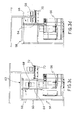
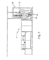
- Figures 6, 7 and 8 show further alternative embodiments of the sliver drawing winder apparatus according to the invention.
- 1 is a general reference for a sliver drawing winder apparatus according to the invention.
- the sliver drawing winder apparatus 1 is fed by a plurality of slivers N resulting from the processing carried out on fibres partially opened and cleaned by carding machines (not shown) and deposited in separate accumulations, each in a can 2.
- One or more cans 2 form regions of deposition 4 of the sliver, being set in positions adjacent to means 6 which guide and feed the sliver N to a machine body 8 belonging to the said sliver drawing winder apparatus 1.
- the means 6 which guide and feed the sliver N to the machine body 8 of the sliver drawing winder apparatus 1 comprise a plurality of control can calenders and sliver guide devices for taking the said slivers N from each can 2 and directing them to the said machine body 8, laying them side by side and approximately parallel with each other.
- the said sliver cans 2 and the said means for guiding and feeding the sliver to the machine body 8 form one so-called creel 10 or unit for feeding the sliver N to the sliver drawing winder apparatus 1.
- the sliver drawing winder apparatus 1 works with a plurality of sliver feed creels which are lined up next to the machine body 8 of the said sliver drawing winder apparatus and feed the said machine body in parallel.
- the said sliver drawing winder apparatus operates with a first feed creel 10 and with a second feed creel 12.
- the slivers carried by the creel 10 are fed to a drafting unit 14 of the sliver drawing winder apparatus 1, in which suitable guides bring the said slivers together to form a web.
- the slivers fed by the creel 10 are placed side by side by the channelling action of the said guides, and the said web is the result.
- the drafting unit 14 also includes pairs of opposing drafting rollers through which the said web is passed in order to apply a predefined draft.
- the drafted web is conveyed on a chute 16 which deflects it onto a bed 18 of the machine body 8 of the said sliver drawing winder.
- the said web is deflected through an angle of 90° with respect to the direction at which it comes out of the drafting unit 14, and is laid on the said bed.
- the second creel 12 feeds a second draft unit from which a web emerges and is deflected by a second chute onto the said bed 18.
- the web that emerges from the second chute is laid on top of the web from the first chute 16, and together they are pressed to a suitable degree by a pair of calenders 20 to produce a web which is then fed to a tapering device 22.
- the tapering device 22 comprises a plurality of opposing guides which work on the web with a tapering action that compacts the lateral edges of the said web.
- the said guides compact the outermost slivers making up the web, i.e. the extreme lateral slivers, so that they do not peel off from the rest of the fibres.
- the web After being passed through the opposing rollers of a surface-smoothing frame, in order to further compact the web, the web is sent to the lap forming unit 24.
- the lap forming unit 24 comprises a plurality of pressure calenders and at least one forming roller.
- the said forming unit 24 comprises three pressure calenders 26, set against each other in such a way that the lap undergoes two calendering passes, and two forming rollers 28 and 28'.
- the said forming unit also comprises a pair of lateral containment plates 30 and a piston 32 for moving the said plates.
- the tube which is coaxial with the plates, is pressed by the action of the said plates against the forming rollers 28 and 28'.
- the said tube In the course of winding the said tube is rotated by the rotation of the forming rollers 28 and 28' and the plates adjust their position as the thickness of the growing web increases, in such a way that the said web is always pressed against the said forming rollers.
- the plates lift the lap to detach it from the forming rollers 28 and 28' and the web is torn by a rotating pneumatic roller which turns the plate assembly in the tearing direction.
- the containment plates are moved away from the lap along the axis of the tube so that the said lap is free to roll towards a device 34 which will prepare the end of the lap, preferably in abutment against the stop shoulder 35, in an end-preparing position.
- the said end-preparing device 34 comprises lap-unwinding means comprising a pair of unwinding rollers.
- the said end-preparing device 34 comprising a first unwinding roller 36 and a second unwinding roller 38.
- the said lap-unwinding means comprise a suction device 39.
- the sliver drawing winder apparatus 1 comprises a device 34' for positioning the prepared end of the lap relative to the said lap, for example relative to its axis.
- the said positioning device 34' preferably comprises the said unwinding rollers 36, 38 and positioning sensors for detecting the completion of a predetermined rotation of the said unwinding rollers 36, 38.
- Sensors for detecting the presence of the lap at the unwinding means that is at the unwinding rollers 36, 38, detect the said presence so that actuation of the unwinding rollers and of the suction device 39 causes unwinding of the lap.
- the said means comprise means for gripping the web 42, tearing means 44 and means for detecting the position of the free end of the lap 46.
- the said tearing means are downstream of the said gripping means with respect to the direction of forward travel of the free end of the unwinding web, while the said means for detecting the position of the free end of the lap are downstream of the said tearing means.
- the said gripping means comprise a pair consisting of a grip 48 with an opposing wall 50, while the said tearing means comprise a pair of tearing rollers 52 and 52'. Additionally, the said means for detecting the position of the free end of the lap comprise a position sensor 54.
- the said position sensor 54 preferably comprises a photoelectric cell.
- the said web is gripped by the said gripping means along a so-called grip line Lp.
- the said web is squeezed by the tearing means along a pull line Lt.
- the rotation of the tearing rollers 52, 52' causes the said lap to be frayed.
- the two rollers are turned in opposite directions so as to stretch the portion of lap lying between the grip line Lp and the pull line Lt.
- a frayed tear line Ls is produced by the action of the tearing means.
- the position of this line is determined by, among other things, the length of the fibres of which the web is composed.
- the frayed tear line Ls occurs between the grip line Lp and the pull line Lt of the tearing rollers, which gives the lap a prepared end whose position with respect to the lap itself (for example with respect to the lap's axis) is sufficiently defined for subsequent processing of the lap.
- the tearing means are deactivated and the gripping means released.
- the tear line of the web which is the new prepared end, has a defined position between the position of the grip line and the position of the pull line.
- the positioning device 34' is activated in order to move the prepared end of the lap out of the fraying means 40 and into a position defined by the said predetermined rotation.
- the unwinding rollers 36, 38 perform a predetermined rotation in the opposite direction to the rotation carried out for the introduction of the free end of the lap into the fraying means 40, in order to move the prepared end of the lap out of the fraying means 40 and into a position defined by the said predetermined rotation.
- the position of the prepared end of the lap with respect to the lap itself (for example with respect to the lap's axis) is sufficiently defined for the subsequent processing of the lap.
- the sufficiently defined position of the prepared end of the lap is maintained without variation in the course of the subsequent movements of the lap to the combing machines.
- the said lap preparing apparatus 34 also includes means for lifting the lap with its prepared end, which comprises, for example, a lifting carriage 56.
- the said lifting carriage 56 is integrated with the said unwinding rollers 36, 38 of the end-preparing and positioning device 34.
- the said sliver drawing winder apparatus also comprises means 58 for transferring the lap from the sliver drawing winder apparatus to the machines downstream of the said sliver drawing winder apparatus.
- the carriage 56 rises, carrying the lap from the end-preparing position to a loading position, the said loading position being such as to engage the said lap with the transfer means 58, which will transfer the said lap from the loading position on the sliver drawing winder apparatus to a feeding position in which the lap is fed towards textile machines downstream of the said sliver drawing winder apparatus.
- the said transfer means comprise a preferably L-shaped supporting frame 60 comprising a cantilever portion 62 that supports a hook-supporting column 64 capable of translational movement ( Figures 3a to 3d).
- a hook 66 is capable of translational movement on the said column 64 between a lowered position, suitable for picking up the lap, and a raised position, suitable for transferring the lap to the feeding position.
- the hook 66 in the lowered position, moves towards the lap which is in the loading position by virtue of the displacement of the column 64 towards the said lap, until a rod 68 on the said hook 66 is inserted into the tube of the lap.
- the hook rises to the raised position on the column 64, taking the lap to an intermediate position.
- the said position from which the lap is to be fed to the downstream machines is provided with means for thus feeding the lap to the said downstream machines, such as a conveyor belt 70.
- the said transfer means advantageously carry the said lap from the end-preparing position to the feeding-to-downstream-machines position without any change in the position of the prepared end relative to the lap.
- the said conveyor belt 70 is preferably provided with lap holding means.
- the said lap holding means comprise a supporting surface 72 and holding shoulders 72' and 72' ' set at a certain distance apart to prevent the lap from rolling.
- the said holding means advantageously enable the lap to be transported towards the downstream machines without any change to the relative position of the prepared end of the lap, that is of the new free end.
- the said conveyor belt 70 is located near the floor on which the said sliver drawing winder apparatus stands or is positioned in such a way that the laps placed on the belt are at a height above the said floor approximately equal to the height of the prepared laps (Figure 8).
- the said sliver drawing winder apparatus also comprises a device 74 for feeding the tubes to the lap forming unit 24.
- the said feeding device 74 is fed with tubes cleaned by machinery (not shown) and conveyed by means to a feeding station.
- a feeding path 78 consisting for example of tracks and chutes, connects the said feeding station to the lap forming unit 24, allowing the said tubes to be fed to the said unit for lap formation.
- the spinning line is advantageously simplified in terms of construction by virtue of the integration of a single tube feeding device 74 into the said sliver drawing winder apparatus.
- the said sliver drawing winding apparatus 1 is situated upstream of textile machines such as, for example, a plurality of combing machines 100 ( Figure 5).
- the said combing machines are preferably arranged in parallel. In other words they work separate laps independently of each other.
- Each combing machine is preferably equipped with a station 102 for receiving a set of laps with prepared ends, e.g. a set composed of eight laps with prepared ends.
- the means of feeding the laps to the combing machines 104 feed the said laps to the combing machines at the said stations 102, moving along at least one transfer path 106, which at least partly branches off towards the said combing machines.
- the said feeding means equipped with the said holding means, advantageously enable the said laps, with their prepared ends, to be transferred to the station 102 of each combing machine 100 without any change in the position of the prepared end.
- the lap is produced by the sliver drawing winder apparatus 1 or by a plurality of apparatus.
- the end of the lap is prepared, that is to say, its free end is frayed, resulting in a prepared end which is in a predefined position with respect to the axis of the lap.
- the laps with their prepared ends are fed to the combing machines 100, which may for example be laid out in parallel, arriving at the stations 102 of these machines, using lap transferring, feeding and unloading means which do not change the position of the prepared end of the lap with respect to the lap axis.
- the lap positioned on combing machine 100 has a prepared end which is already in a sufficiently predefined position with respect to the lap itself, so that the web can be reattached to the web of a nearly-finished lap.
- the spinning line has a sliver drawing winder apparatus or a plurality of apparatus capable of feeding laps with ready-prepared ends to the combing machines.
- the said combing machines do not have special apparatus for preparing the lap, so their structure is simplified.
- a single sliver drawing winder apparatus or a plurality of sliver drawing winders arranged upstream of the combing machines in a spinning line, feed laps with prepared ends to the combing machines downstream, thus simplifying the structure and functionality of the said combing machines.
- the said sliver drawing winder apparatus avoids line synchronizing problems arising from the feeding of the laps and the preparing of their ends in the case in which end preparation occurs directly at the combing machine itself.
- Another advantage of the sliver drawing winder apparatus according to the invention is the provision of lap unwinding means integrated into lifting means which move it to a position suitable for transfer to the comb feeding means.
- the benefit of this is that it avoids further rolling or rotation of the lap so that the position of the prepared end with respect to the axis of the lap cannot change. It also safeguards the integrity of the web against knocks due to its displacement.
- the spinning line has means of transferring the lap to the combing machines that do not modify the position of the prepared end with respect to the lap's axis.
- the spinning line has means of feeding the lap with its prepared end to the combing machines which do not modify the position of the prepared end with respect to the lap's axis.
- the said sliver drawing winder apparatus operates with a carriage for transporting the lap to the combing machines in the conventional way, e.g. by pushing the carriage.
Landscapes
- Engineering & Computer Science (AREA)
- Textile Engineering (AREA)
- Preliminary Treatment Of Fibers (AREA)
- Pharmaceuticals Containing Other Organic And Inorganic Compounds (AREA)
Priority Applications (3)
| Application Number | Priority Date | Filing Date | Title |
|---|---|---|---|
| EP03425209A EP1464739B1 (de) | 2003-04-04 | 2003-04-04 | Wattewickel-Maschine und Verfahren |
| AT03425209T ATE407239T1 (de) | 2003-04-04 | 2003-04-04 | Wattewickel-maschine und verfahren |
| DE60323329T DE60323329D1 (de) | 2003-04-04 | 2003-04-04 | Wattewickel-Maschine und Verfahren |
Applications Claiming Priority (1)
| Application Number | Priority Date | Filing Date | Title |
|---|---|---|---|
| EP03425209A EP1464739B1 (de) | 2003-04-04 | 2003-04-04 | Wattewickel-Maschine und Verfahren |
Publications (2)
| Publication Number | Publication Date |
|---|---|
| EP1464739A1 true EP1464739A1 (de) | 2004-10-06 |
| EP1464739B1 EP1464739B1 (de) | 2008-09-03 |
Family
ID=32842911
Family Applications (1)
| Application Number | Title | Priority Date | Filing Date |
|---|---|---|---|
| EP03425209A Expired - Lifetime EP1464739B1 (de) | 2003-04-04 | 2003-04-04 | Wattewickel-Maschine und Verfahren |
Country Status (3)
| Country | Link |
|---|---|
| EP (1) | EP1464739B1 (de) |
| AT (1) | ATE407239T1 (de) |
| DE (1) | DE60323329D1 (de) |
Cited By (4)
| Publication number | Priority date | Publication date | Assignee | Title |
|---|---|---|---|---|
| CN101016662B (zh) * | 2007-02-13 | 2010-05-19 | 江苏凯宫机械股份有限公司 | 条并卷机 |
| ITBS20080232A1 (it) * | 2008-12-19 | 2010-06-20 | Marzoli Spa | Dispositivo di formazione della teletta per macchine per la lavorazione di nastri di fibra, ad esempio per uno stiroriunitore |
| ITBS20090237A1 (it) * | 2009-12-28 | 2011-06-29 | Marzoli Combing & Flyer S P A | Dispositivo di stiro di uno stiratoio o di uno stiroriunitore |
| WO2011077267A1 (en) | 2009-12-24 | 2011-06-30 | Marzoli Combing & Flyer S.P.A. | Lap winding device for a textile machine, for example a lap-winder, provided with an auxiliary belt |
Citations (4)
| Publication number | Priority date | Publication date | Assignee | Title |
|---|---|---|---|---|
| EP0349852A2 (de) * | 1988-07-05 | 1990-01-10 | Maschinenfabrik Rieter Ag | Automatisches Zuführungsverfahren von Kämmaschinen |
| US5337456A (en) * | 1990-10-22 | 1994-08-16 | Rieter Machine Works, Ltd. | Method and apparatus for opening a wadding lap |
| EP0677603A2 (de) * | 1988-11-03 | 1995-10-18 | Maschinenfabrik Rieter Ag | Kämmaschine |
| EP0718422A1 (de) * | 1994-12-22 | 1996-06-26 | Maschinenfabrik Rieter Ag | Maschine zum Herstellen von Wattewickeln aus Faserbändern |
-
2003
- 2003-04-04 DE DE60323329T patent/DE60323329D1/de not_active Expired - Lifetime
- 2003-04-04 EP EP03425209A patent/EP1464739B1/de not_active Expired - Lifetime
- 2003-04-04 AT AT03425209T patent/ATE407239T1/de not_active IP Right Cessation
Patent Citations (4)
| Publication number | Priority date | Publication date | Assignee | Title |
|---|---|---|---|---|
| EP0349852A2 (de) * | 1988-07-05 | 1990-01-10 | Maschinenfabrik Rieter Ag | Automatisches Zuführungsverfahren von Kämmaschinen |
| EP0677603A2 (de) * | 1988-11-03 | 1995-10-18 | Maschinenfabrik Rieter Ag | Kämmaschine |
| US5337456A (en) * | 1990-10-22 | 1994-08-16 | Rieter Machine Works, Ltd. | Method and apparatus for opening a wadding lap |
| EP0718422A1 (de) * | 1994-12-22 | 1996-06-26 | Maschinenfabrik Rieter Ag | Maschine zum Herstellen von Wattewickeln aus Faserbändern |
Cited By (8)
| Publication number | Priority date | Publication date | Assignee | Title |
|---|---|---|---|---|
| CN101016662B (zh) * | 2007-02-13 | 2010-05-19 | 江苏凯宫机械股份有限公司 | 条并卷机 |
| ITBS20080232A1 (it) * | 2008-12-19 | 2010-06-20 | Marzoli Spa | Dispositivo di formazione della teletta per macchine per la lavorazione di nastri di fibra, ad esempio per uno stiroriunitore |
| WO2010070608A1 (en) | 2008-12-19 | 2010-06-24 | Marzoli S.P.A. | Lap-forming device for machines manufacturing fibre webs, such as a lap-winder |
| CN102282300A (zh) * | 2008-12-19 | 2011-12-14 | 马佐里股份公司 | 诸如成卷机之类的用于制造纤维网的机器的卷形成装置 |
| CN102282300B (zh) * | 2008-12-19 | 2014-05-07 | 马佐里股份公司 | 诸如成卷机之类的用于制造纤维网的机器的卷形成装置 |
| WO2011077267A1 (en) | 2009-12-24 | 2011-06-30 | Marzoli Combing & Flyer S.P.A. | Lap winding device for a textile machine, for example a lap-winder, provided with an auxiliary belt |
| ITBS20090237A1 (it) * | 2009-12-28 | 2011-06-29 | Marzoli Combing & Flyer S P A | Dispositivo di stiro di uno stiratoio o di uno stiroriunitore |
| WO2011080611A1 (en) | 2009-12-28 | 2011-07-07 | Marzoli Combing & Flyer S.P.A. | Draft device of a drafting machine or a lap - forming machine |
Also Published As
| Publication number | Publication date |
|---|---|
| ATE407239T1 (de) | 2008-09-15 |
| DE60323329D1 (de) | 2008-10-16 |
| EP1464739B1 (de) | 2008-09-03 |
Similar Documents
| Publication | Publication Date | Title |
|---|---|---|
| CN110331483B (zh) | 一种全流程智能纺纱生产线 | |
| US4125990A (en) | Open-end spinning machine | |
| EP0069087B1 (de) | Verfahren und Vorrichtung zum Beladen eines Gatters und zum Verbinden von faserverarbeitenden Maschinen | |
| CZ146091A3 (en) | Process and apparatus for automatic feeding a fiber strand to a textile machine | |
| CZ283134B6 (cs) | Způsob a zařízení pro zapřádání příze na rotorovém dopřádacím stroji | |
| EP1464739B1 (de) | Wattewickel-Maschine und Verfahren | |
| US4987645A (en) | Automatic piecing of overlapped leading and trailing ends of slivers in a textile machine | |
| CN108069291B (zh) | 用于将纱线端沉积在筒管上的方法、装置和纺纱卷绕机 | |
| ITMI950025A1 (it) | Sistema di distribuzione e movimentazione delle spole alle stazioni di raccatura di una raccatrice automatica | |
| US5092531A (en) | Assembly for preparing yarn ends of yarn packages for unwinding at a textile winding machine | |
| CN104973438B (zh) | 用于卷绕纤维条的卷绕机和用于卷绕纤维条的方法 | |
| CN103025936A (zh) | 用于绕卷机的卷形成装置 | |
| US5038441A (en) | Combing machine having apparatus for changing lap rolls | |
| US4866814A (en) | Process and apparatus to fine one end in a textile fiber band or sliver and to engage said end to feed members in a textile machine | |
| EP0603125B1 (de) | Verfahren und Vorrichtung für die Watte-Endenverbindung | |
| CN102549205A (zh) | 具有纤维条导向机构的精梳机 | |
| CZ281430B6 (cs) | Způsob a zařízení k navíjení nitě na kuželovou cívku u dopřádacích strojů s otevřeným koncem | |
| US6079195A (en) | Procedure for re-equipping and simultaneous modernization of an open end rotor spinning machine | |
| US5778493A (en) | Device and method for automatically replacing the feed lap packages and for preparing and joining the relative edges in a combing machine | |
| CN108069285B (zh) | 用于以定义的方式将纱线端沉积在筒管上的方法、用于执行该方法的装置和纺纱卷绕机 | |
| ITMI950028A1 (it) | Dispositivo per la movimentazione delle spole in una roccatrice automatica | |
| US10577728B2 (en) | Method for preparing a workstation for resumption of the spinning process on an air-jet spinning machine, and an air-jet spinning machine for performing the method | |
| US6449805B2 (en) | Follow-up system for a reserve lap in a combing machine | |
| US6167595B1 (en) | Method and device for automatically replacing the lap, preparing and joining its edges and restarting it in a combing machine | |
| JPH01299117A (ja) | 高低差を克服するための搬送システム |
Legal Events
| Date | Code | Title | Description |
|---|---|---|---|
| PUAI | Public reference made under article 153(3) epc to a published international application that has entered the european phase |
Free format text: ORIGINAL CODE: 0009012 |
|
| AK | Designated contracting states |
Kind code of ref document: A1 Designated state(s): AT BE BG CH CY CZ DE DK EE ES FI FR GB GR HU IE IT LI LU MC NL PT RO SE SI SK TR |
|
| AX | Request for extension of the european patent |
Extension state: AL LT LV MK |
|
| 17P | Request for examination filed |
Effective date: 20041117 |
|
| AKX | Designation fees paid |
Designated state(s): AT BE BG CH CY CZ DE DK EE ES FI FR GB GR HU IE IT LI LU MC NL PT RO SE SI SK TR |
|
| 17Q | First examination report despatched |
Effective date: 20060628 |
|
| GRAP | Despatch of communication of intention to grant a patent |
Free format text: ORIGINAL CODE: EPIDOSNIGR1 |
|
| GRAS | Grant fee paid |
Free format text: ORIGINAL CODE: EPIDOSNIGR3 |
|
| GRAA | (expected) grant |
Free format text: ORIGINAL CODE: 0009210 |
|
| AK | Designated contracting states |
Kind code of ref document: B1 Designated state(s): AT BE BG CH CY CZ DE DK EE ES FI FR GB GR HU IE IT LI LU MC NL PT RO SE SI SK TR |
|
| REG | Reference to a national code |
Ref country code: GB Ref legal event code: FG4D |
|
| REG | Reference to a national code |
Ref country code: CH Ref legal event code: EP |
|
| REG | Reference to a national code |
Ref country code: IE Ref legal event code: FG4D |
|
| REF | Corresponds to: |
Ref document number: 60323329 Country of ref document: DE Date of ref document: 20081016 Kind code of ref document: P |
|
| REG | Reference to a national code |
Ref country code: CH Ref legal event code: NV Representative=s name: JACOBACCI & PARTNERS S.P.A. |
|
| PG25 | Lapsed in a contracting state [announced via postgrant information from national office to epo] |
Ref country code: NL Free format text: LAPSE BECAUSE OF FAILURE TO SUBMIT A TRANSLATION OF THE DESCRIPTION OR TO PAY THE FEE WITHIN THE PRESCRIBED TIME-LIMIT Effective date: 20080903 Ref country code: ES Free format text: LAPSE BECAUSE OF FAILURE TO SUBMIT A TRANSLATION OF THE DESCRIPTION OR TO PAY THE FEE WITHIN THE PRESCRIBED TIME-LIMIT Effective date: 20081214 |
|
| PG25 | Lapsed in a contracting state [announced via postgrant information from national office to epo] |
Ref country code: AT Free format text: LAPSE BECAUSE OF FAILURE TO SUBMIT A TRANSLATION OF THE DESCRIPTION OR TO PAY THE FEE WITHIN THE PRESCRIBED TIME-LIMIT Effective date: 20080903 Ref country code: SI Free format text: LAPSE BECAUSE OF FAILURE TO SUBMIT A TRANSLATION OF THE DESCRIPTION OR TO PAY THE FEE WITHIN THE PRESCRIBED TIME-LIMIT Effective date: 20080903 Ref country code: FI Free format text: LAPSE BECAUSE OF FAILURE TO SUBMIT A TRANSLATION OF THE DESCRIPTION OR TO PAY THE FEE WITHIN THE PRESCRIBED TIME-LIMIT Effective date: 20080903 |
|
| NLV1 | Nl: lapsed or annulled due to failure to fulfill the requirements of art. 29p and 29m of the patents act | ||
| PG25 | Lapsed in a contracting state [announced via postgrant information from national office to epo] |
Ref country code: BE Free format text: LAPSE BECAUSE OF FAILURE TO SUBMIT A TRANSLATION OF THE DESCRIPTION OR TO PAY THE FEE WITHIN THE PRESCRIBED TIME-LIMIT Effective date: 20080903 |
|
| PG25 | Lapsed in a contracting state [announced via postgrant information from national office to epo] |
Ref country code: BG Free format text: LAPSE BECAUSE OF FAILURE TO SUBMIT A TRANSLATION OF THE DESCRIPTION OR TO PAY THE FEE WITHIN THE PRESCRIBED TIME-LIMIT Effective date: 20081203 |
|
| PG25 | Lapsed in a contracting state [announced via postgrant information from national office to epo] |
Ref country code: RO Free format text: LAPSE BECAUSE OF FAILURE TO SUBMIT A TRANSLATION OF THE DESCRIPTION OR TO PAY THE FEE WITHIN THE PRESCRIBED TIME-LIMIT Effective date: 20080903 Ref country code: PT Free format text: LAPSE BECAUSE OF FAILURE TO SUBMIT A TRANSLATION OF THE DESCRIPTION OR TO PAY THE FEE WITHIN THE PRESCRIBED TIME-LIMIT Effective date: 20090203 Ref country code: CZ Free format text: LAPSE BECAUSE OF FAILURE TO SUBMIT A TRANSLATION OF THE DESCRIPTION OR TO PAY THE FEE WITHIN THE PRESCRIBED TIME-LIMIT Effective date: 20080903 Ref country code: SK Free format text: LAPSE BECAUSE OF FAILURE TO SUBMIT A TRANSLATION OF THE DESCRIPTION OR TO PAY THE FEE WITHIN THE PRESCRIBED TIME-LIMIT Effective date: 20080903 |
|
| PLBE | No opposition filed within time limit |
Free format text: ORIGINAL CODE: 0009261 |
|
| STAA | Information on the status of an ep patent application or granted ep patent |
Free format text: STATUS: NO OPPOSITION FILED WITHIN TIME LIMIT |
|
| PG25 | Lapsed in a contracting state [announced via postgrant information from national office to epo] |
Ref country code: DK Free format text: LAPSE BECAUSE OF FAILURE TO SUBMIT A TRANSLATION OF THE DESCRIPTION OR TO PAY THE FEE WITHIN THE PRESCRIBED TIME-LIMIT Effective date: 20080903 Ref country code: EE Free format text: LAPSE BECAUSE OF FAILURE TO SUBMIT A TRANSLATION OF THE DESCRIPTION OR TO PAY THE FEE WITHIN THE PRESCRIBED TIME-LIMIT Effective date: 20080903 |
|
| 26N | No opposition filed |
Effective date: 20090604 |
|
| GBPC | Gb: european patent ceased through non-payment of renewal fee |
Effective date: 20090404 |
|
| REG | Reference to a national code |
Ref country code: FR Ref legal event code: ST Effective date: 20091231 |
|
| PG25 | Lapsed in a contracting state [announced via postgrant information from national office to epo] |
Ref country code: SE Free format text: LAPSE BECAUSE OF FAILURE TO SUBMIT A TRANSLATION OF THE DESCRIPTION OR TO PAY THE FEE WITHIN THE PRESCRIBED TIME-LIMIT Effective date: 20081203 |
|
| PG25 | Lapsed in a contracting state [announced via postgrant information from national office to epo] |
Ref country code: FR Free format text: LAPSE BECAUSE OF NON-PAYMENT OF DUE FEES Effective date: 20091222 Ref country code: GB Free format text: LAPSE BECAUSE OF NON-PAYMENT OF DUE FEES Effective date: 20090404 Ref country code: MC Free format text: LAPSE BECAUSE OF NON-PAYMENT OF DUE FEES Effective date: 20090430 Ref country code: IE Free format text: LAPSE BECAUSE OF NON-PAYMENT OF DUE FEES Effective date: 20090404 |
|
| PG25 | Lapsed in a contracting state [announced via postgrant information from national office to epo] |
Ref country code: GR Free format text: LAPSE BECAUSE OF FAILURE TO SUBMIT A TRANSLATION OF THE DESCRIPTION OR TO PAY THE FEE WITHIN THE PRESCRIBED TIME-LIMIT Effective date: 20081204 |
|
| PG25 | Lapsed in a contracting state [announced via postgrant information from national office to epo] |
Ref country code: LU Free format text: LAPSE BECAUSE OF NON-PAYMENT OF DUE FEES Effective date: 20090404 |
|
| PG25 | Lapsed in a contracting state [announced via postgrant information from national office to epo] |
Ref country code: HU Free format text: LAPSE BECAUSE OF FAILURE TO SUBMIT A TRANSLATION OF THE DESCRIPTION OR TO PAY THE FEE WITHIN THE PRESCRIBED TIME-LIMIT Effective date: 20090304 |
|
| PG25 | Lapsed in a contracting state [announced via postgrant information from national office to epo] |
Ref country code: CY Free format text: LAPSE BECAUSE OF FAILURE TO SUBMIT A TRANSLATION OF THE DESCRIPTION OR TO PAY THE FEE WITHIN THE PRESCRIBED TIME-LIMIT Effective date: 20080903 |
|
| REG | Reference to a national code |
Ref country code: CH Ref legal event code: PCAR Free format text: NEW ADDRESS: VIA LUGANETTO 3, 6962 LUGANO (CH) |
|
| PGFP | Annual fee paid to national office [announced via postgrant information from national office to epo] |
Ref country code: IT Payment date: 20150225 Year of fee payment: 13 |
|
| PG25 | Lapsed in a contracting state [announced via postgrant information from national office to epo] |
Ref country code: IT Free format text: LAPSE BECAUSE OF NON-PAYMENT OF DUE FEES Effective date: 20160404 |
|
| PGFP | Annual fee paid to national office [announced via postgrant information from national office to epo] |
Ref country code: TR Payment date: 20200406 Year of fee payment: 18 Ref country code: CH Payment date: 20200420 Year of fee payment: 18 Ref country code: DE Payment date: 20200430 Year of fee payment: 18 |
|
| REG | Reference to a national code |
Ref country code: DE Ref legal event code: R119 Ref document number: 60323329 Country of ref document: DE |
|
| PG25 | Lapsed in a contracting state [announced via postgrant information from national office to epo] |
Ref country code: LI Free format text: LAPSE BECAUSE OF NON-PAYMENT OF DUE FEES Effective date: 20210430 Ref country code: CH Free format text: LAPSE BECAUSE OF NON-PAYMENT OF DUE FEES Effective date: 20210430 Ref country code: DE Free format text: LAPSE BECAUSE OF NON-PAYMENT OF DUE FEES Effective date: 20211103 |