EP1462609A1 - Turbomaschinenschaufel mit vermindertem Gewicht und deren Herstellungsweise - Google Patents
Turbomaschinenschaufel mit vermindertem Gewicht und deren Herstellungsweise Download PDFInfo
- Publication number
- EP1462609A1 EP1462609A1 EP04290787A EP04290787A EP1462609A1 EP 1462609 A1 EP1462609 A1 EP 1462609A1 EP 04290787 A EP04290787 A EP 04290787A EP 04290787 A EP04290787 A EP 04290787A EP 1462609 A1 EP1462609 A1 EP 1462609A1
- Authority
- EP
- European Patent Office
- Prior art keywords
- cover
- blade
- flank
- welding
- socket
- Prior art date
- Legal status (The legal status is an assumption and is not a legal conclusion. Google has not performed a legal analysis and makes no representation as to the accuracy of the status listed.)
- Granted
Links
Images


Classifications
-
- B—PERFORMING OPERATIONS; TRANSPORTING
- B23—MACHINE TOOLS; METAL-WORKING NOT OTHERWISE PROVIDED FOR
- B23K—SOLDERING OR UNSOLDERING; WELDING; CLADDING OR PLATING BY SOLDERING OR WELDING; CUTTING BY APPLYING HEAT LOCALLY, e.g. FLAME CUTTING; WORKING BY LASER BEAM
- B23K20/00—Non-electric welding by applying impact or other pressure, with or without the application of heat, e.g. cladding or plating
- B23K20/12—Non-electric welding by applying impact or other pressure, with or without the application of heat, e.g. cladding or plating the heat being generated by friction; Friction welding
- B23K20/122—Non-electric welding by applying impact or other pressure, with or without the application of heat, e.g. cladding or plating the heat being generated by friction; Friction welding using a non-consumable tool, e.g. friction stir welding
-
- B—PERFORMING OPERATIONS; TRANSPORTING
- B23—MACHINE TOOLS; METAL-WORKING NOT OTHERWISE PROVIDED FOR
- B23P—METAL-WORKING NOT OTHERWISE PROVIDED FOR; COMBINED OPERATIONS; UNIVERSAL MACHINE TOOLS
- B23P15/00—Making specific metal objects by operations not covered by a single other subclass or a group in this subclass
- B23P15/04—Making specific metal objects by operations not covered by a single other subclass or a group in this subclass turbine or like blades from several pieces
-
- F—MECHANICAL ENGINEERING; LIGHTING; HEATING; WEAPONS; BLASTING
- F01—MACHINES OR ENGINES IN GENERAL; ENGINE PLANTS IN GENERAL; STEAM ENGINES
- F01D—NON-POSITIVE DISPLACEMENT MACHINES OR ENGINES, e.g. STEAM TURBINES
- F01D5/00—Blades; Blade-carrying members; Heating, heat-insulating, cooling or antivibration means on the blades or the members
- F01D5/12—Blades
- F01D5/14—Form or construction
- F01D5/147—Construction, i.e. structural features, e.g. of weight-saving hollow blades
-
- F—MECHANICAL ENGINEERING; LIGHTING; HEATING; WEAPONS; BLASTING
- F01—MACHINES OR ENGINES IN GENERAL; ENGINE PLANTS IN GENERAL; STEAM ENGINES
- F01D—NON-POSITIVE DISPLACEMENT MACHINES OR ENGINES, e.g. STEAM TURBINES
- F01D5/00—Blades; Blade-carrying members; Heating, heat-insulating, cooling or antivibration means on the blades or the members
- F01D5/12—Blades
- F01D5/14—Form or construction
- F01D5/18—Hollow blades, i.e. blades with cooling or heating channels or cavities; Heating, heat-insulating or cooling means on blades
-
- Y—GENERAL TAGGING OF NEW TECHNOLOGICAL DEVELOPMENTS; GENERAL TAGGING OF CROSS-SECTIONAL TECHNOLOGIES SPANNING OVER SEVERAL SECTIONS OF THE IPC; TECHNICAL SUBJECTS COVERED BY FORMER USPC CROSS-REFERENCE ART COLLECTIONS [XRACs] AND DIGESTS
- Y02—TECHNOLOGIES OR APPLICATIONS FOR MITIGATION OR ADAPTATION AGAINST CLIMATE CHANGE
- Y02T—CLIMATE CHANGE MITIGATION TECHNOLOGIES RELATED TO TRANSPORTATION
- Y02T50/00—Aeronautics or air transport
- Y02T50/60—Efficient propulsion technologies, e.g. for aircraft
-
- Y—GENERAL TAGGING OF NEW TECHNOLOGICAL DEVELOPMENTS; GENERAL TAGGING OF CROSS-SECTIONAL TECHNOLOGIES SPANNING OVER SEVERAL SECTIONS OF THE IPC; TECHNICAL SUBJECTS COVERED BY FORMER USPC CROSS-REFERENCE ART COLLECTIONS [XRACs] AND DIGESTS
- Y10—TECHNICAL SUBJECTS COVERED BY FORMER USPC
- Y10T—TECHNICAL SUBJECTS COVERED BY FORMER US CLASSIFICATION
- Y10T29/00—Metal working
- Y10T29/49—Method of mechanical manufacture
- Y10T29/49316—Impeller making
- Y10T29/49336—Blade making
- Y10T29/49339—Hollow blade
Definitions
- the invention relates to turbine engine blades and more particularly to a structure and process for manufacturing light and hollow metal blades intended for example for the rotors of compressors or blowers of turbojets with double flow propelling airplanes.
- Turbojet parts used in aeronautics must combine characteristics of lightness, resistance to vibration and resistance to fatigue This is particularly the case for the blades mounted on the periphery of the bladed rotors. compressor or blower.
- Such blades have very thin blades which are the seat of alternating stresses in tension and compression likely to cause rupture by the appearance and propagation of cracks on their sides
- the method of manufacturing such blades must be very reliable in order to space the maximum quality controls.
- the first technology is disclosed for example by patent FR 2 688 264 and its corresponding US 5,295,789.
- the blade is metallic and has on the underside a plurality of through cells and filled with low density organic material, the reduction thus obtained being directly proportional to the total volume of the cells, the organic gasket ensuring the continuity of the lower surface as well as a role of shock absorber vibration.
- the disadvantage of this technology is that a significant reduction leads to increase the volume of the alveoli and by repercussion to weaken the dawn and make it more flexible. In addition, the dawn resonant frequencies are lowered so that the cushioning provided by the lining decreases. This disadvantage is reduced but not deleted with the dawn disclosed by US patent 5,634,771, this dawn having ribs arranged for better rigidity
- the second technology is disclosed by patent FR 2 754 478 corresponding to US Patent 5,896,658.
- the blade is in two parts assembled by diffusion welding, the junction surface between these two parts going from the leading edge to the trailing edges, anti-diffusion treatment being applied to the places of the junction surface where will be future cavities, the lightening cavities being obtained by hot inflation after diffusion welding.
- This technology makes it possible to obtain very efficient blades, but the manufacturing process has the disadvantage of being long and expensive.
- patent FR 2 695 163 corresponding to US patent 5,346,613 discloses a lightened blade having in the thickness direction a plurality of through holes and closed by plugs welded at their periphery with a high energy beam like a laser beam or an electron beam.
- this technology presents the disadvantage of leaving a large amount of material between the holes and of imposing dawn a very important welding since each hole-plug couple must be welded all around
- the problem to solve is to design a reliable structure and manufacturing process and economical lightened blades, the blades must have high performance in terms of lightness and mechanical resistance.
- the invention proposes a lightened turbine engine blade comprising a metal alloy blade, this blade itself comprising a leading edge, a trailing edge, two sides, a top and a cavity closed by a cover.
- this cover being on one of the two flanks called a hollow side, this cover ensuring the aerodynamic continuity of the hollow side, this cover being linked by the edge to the rest of the blade by a weld bead, the thickness of the edge of the cover being rated EC
- Such a blade is remarkable in that the weld bead opens onto the hollowed flank and penetrates into the blade with a depth P at least equal to the thickness EC of the edge of the cover in order to ensure the continuity of the material between the edge of the cover and the rest of the blade to a depth at least equal to the thickness EC of the edge of the cover
- Such an arrangement increases the mechanical strength and the lifespan of the blade.
- the continuity of material eliminates any slit in the vicinity of the hollow flank and perpendicular to it which may remain between the cover and the rest of the blade, such slits constituting crack initiators liable to propagate on the flank dug under the effect of mechanical stresses located in the vicinity of the hollow flank and oriented tangentially to this flank
- the width LC of the cavity is at least equal to half the width LP of the blade, the width of the blade LP being taken between the leading edge and the edge of leak on the neutral geometric line passing midway between the sides, the width LC of the cavity being taken between the lateral surfaces on the same neutral geometric line
- the weld bead is obtained by the rotation of a finger penetrating from the flank hollowed out between the cover and the rest of the blade.
- this known welding process called “Friction Stir Welding” generates during the welding very great mechanical forces while the blade of a blade is a thin piece little able in itself to resist such forces
- this type of welding is paradoxically applicable in the present case by implementing the method described below.
- This type of welding is particularly interesting because it offers a high quality of weld and an excellent reproducibility allowing to space the controls.
- the welding is carried out with a friction welding machine of the "Friction Stir Welding" type, this machine comprising a table and a spindle capable of relative displacements according to three degrees of freedom in translation and two degrees of freedom in rotation, the spindle rotating a welding tool along a geometric axis of rotation, the welding tool comprising a finger projecting from a shoulder, the blank being arranged in a cradle attached to the table, this cradle comprising a bearing surface of shape complementary to the opposite side of the blank, the blank coming into abutment by its side opposite to said bearing surface, this cradle also comprising stops surrounding the blank to position it laterally in the cradle, the cover being introduced into the socket, the assembly consisting of the blank and the cover being held by a plurality of flanges controlled remotely, l e rotating finger being pressed into the hollow side between the edges of the cover and the rest of the blade, the shoulder then flush with the hollow side, each controlled flange being retracted with the
- Dawn 10 is a well-known object successively comprising from bottom to top in FIG. 1: a foot 20 by which it is nested in a rotor not shown, a platform 30 and a blade 40.
- the blade 40 is slim and arched.
- the blade 40 is delimited laterally forwards by a rounded edge called leading edge 42, towards the rear by a second more tapered edge called trailing edge 44 and laterally by two sides 50.
- the base of the blade 40 will be referenced 56; say the part of the blade 40 against the platform 30, and we will reference 60 the sum: of the blade 40, that is to say the end of the blade 40 opposite the platform 30
- the blade 40 is arched, that is to say that it forms an arc between the leading edge 42 and the trailing edge 44 so that one of the flank 50 is convex while the opposite flank is concave, the convex flank 50 being called upper surface and 50 concave flank being called lower surface
- the width LP of the blade 40 is usually defined between the end 42a of the edge leading edge 42 and the end 44a of the trailing edge 44 When the blade 40 is bent this width LP is taken along a geometric line 46 called "neutral" curve passing midway between the two sides 50
- the thickness EP of the blade 40 is also defined. the maximum distance between the sides 50, this thickness EP being preferably measured at the top 60 of the blade 40
- the blade 40 has in one of its sides 50, called hollow side 50a, a cavity 70 closed by a cover 8C located also in the flank 50a
- a cover 8C located also in the flank 50a
- the flank 50 opposite the hollow flank 50a also refer to 72 and 74 respectively the bottom and the lateral surface of this cavity 70.
- This lateral surface 74 successively runs along the leading edge 42, the base 56 and the trailing edge 44 so as to form a U whose free ends open out at vertex 60 of the blade 40, the cavity 70 thus comprising an opening 76 opening onto this vertex 60.
- References 82, 84, 85 and 86 respectively the external surface, the inner surface, edge and edge of cover 80.
- Outer surface 82 of cover 80 is in the shape of the hollow flank 50a and therefore constitutes the part of the flank hollowed out 50a above the cavity 70.
- the internal surface 84 of the cover 80 is in look from the bottom 72 of the cavity 70
- connection 110 The material of the blade 40 located between the bottom 72 of the cavity 70 and the opposite flank 50b constitutes a connection 110 connecting between them the leading edge 42 and the trailing edge 44.
- the minimum thickness of the connection will be noted ER min 110 the cover 80 and the connection 110 cooperate to ensure the rigidity of the blade 40.
- the cover 80 will be given a minimum thickness EC min at least equal to 0.5 times ER min .
- the width LC of the cavity 70 is at least equal to 50% of the width LP of the blade, the width LC being measured between the lateral surfaces 74 of the cavity along the leading edge 42 and the trailing edge 44, the width LC being measured along the neutral geometric line 46.
- the cover 80 has a minimum thickness EC min at least equal to 20% of the thickness EP of the blade 40 so that this cover participates effectively in the mechanical strength of the blade 40.
- the blade 40 also comprises a weld bead 100 in the hollowed-out flank 50a and flush with the latter, that is to say forming with it neither hollow nor bump, this weld bead 100 along the edge of the cover 80 and penetrating into the depth of the blade 40 with a depth P at least equal to the thickness EC of the edge 85 of the cover 80, this weld bead 100 thus ensuring the connection by continuity of the material from the edge of the cover 80 to the rest of the blade 40 on a depth equal to the thickness EC of the edge of the cover 80.
- the weld bead 100 fully encompasses the lateral surface 94 of the socket 90 as well as the edge 86 facing this lateral surface 94, this lateral surface 94 and this edge 86 therefore disappearing in the weld bead 100
- the weld bead 100 can also include a part of the bearing surface 92 of the socket 90 adjacent to the lateral surface 94 of the socket 90, as well as an identical part of the internal surface 84 of the cover 80 adjacent to edge 86
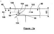
- the weld bead 100 has a depth P less than the thickness EC of the edge 85 of the cover 80. Therefore, a part 86a of the edge 86 and a part 94a of the lateral surface 94 are not linked and then form a crack initiation 102 capable of degenerating into cracks 104 propagating towards the hollowed-out flank 50a and in the opposite direction inside the blade 40 under the effect of the stresses 106 tangential to the flank dug 50a
- the cavity 70 opens onto the top 60 of the blade 40.
- the weld bead 100 therefore has an open U-shape starting and ending at the top 60.
- This U-shape of the weld bead 100 is illustrated by FIG. 1.
- This opening makes it possible to lighten the blade 40 at its top 60 and by repercussion of lightening the complete rotor and effectively reducing its moment of inertia, because this material, which the invention eliminates at the top 60 of the blade 40, has a maximum moment of inertia on the bladed rotor.
- This opening is without consequences on the balancing of the rotor because the centrifugal force caused by the rotation of the bladed rotor prevents foreign bodies from entering cavity 70 or expels those who could have entered this cavity when the bladed rotor was at rest
- the weld 100 can be obtained by brazing. In this case, the lateral surface 94 of the socket 90 as well as the edge 86 facing this lateral surface 94 are physically preserved.
- the weld 100 can also be obtained by fusion with an electron beam or a laser beam
- the inventors explain the excellent homogeneity and reproducibility of the welding of the following the effect of the heat given off, the metal around the finger in rotation is brought to the plastic state and follows a swirling movement around this finger with a decreasing speed gradient when moving away from the finger, such a movement causing the cover metals to mix with the rest of the blade as well as the absorption of porosity and usual shrinkage in the case of welding of parts by alloy fusion
- the geometric axis of rotation 172 of the welding tool 170 follows in space an appropriate trajectory to pass substantially between the lateral surface 94 of the socket 90 and the edge 86 of the cover 80, this geometric axis of rotation 172 arriving in the bearing surface 142 of the cradle 140 and defining there a path not referenced, this bearing surface 142 being substantially in contact with the blade 40 at least in the vicinity of this path. This allows the cradle 140 to resume the penetration force 178 without causing bending on the blade 40 and the cover 80.
- the welding machine used is of the type known as "five axes" with numerical control, it is to say that the relative displacements of the spindle 132 of the machine with respect to the table 130 can be carried out along three axes in translation and two axes in rotation, these movements being controlled by a computer program, the spindle driving rotation of the welding tool 170 along its geometric axis of rotation 172 to cause the friction of this tool against the workpiece
- the finger 174 has a sufficient length under the shoulder 176 for the depth P of the weld bead 100 is greater than the thickness EC at the edge 85 of the cover 80. Therefore, the edge 86 of the cover 80, the side surface 94 of the socket 90 and the space formed by the play that they constitute between them disappears in the cord of weld 100 in formation, these spaces in the form of slots substantially perpendicular to the hollowed out flank 50a being comparable to cracks liable to propagate and cause the break of dawn under the effect of alternating stresses on the hollowed out flank 50a, as illustrated in FIG. 3a.
- the welding tool 170 causes a force in the workpiece. significant 178 penetration located substantially along the geometric axis of rotations 172.
- the bearing face 142 will be given a suitable shape for supporting the blank 10a in line with the weld bead 100 to be produced
- the axis geometric rotation 172 passes through this bearing face 142 during all the welding
- the penetrating force 178 is transmitted to the bearing face 142 by a simple compression of the blank 10a and the cover 80, without causing bending of these two pieces which are very thin.
- the welding tool 170 produces a force tangential to the hollowed-out flank 50a and a large torque which are capable of deforming and laterally displacing the blank 10a laterally relative to the bearing face 142 of the cradle 140 and on the other hand the cover 80 relative to the blank 10a. Therefore, the stops 144 are arranged to position the blank 10a with good precision, for example within 1 mm. These stops will have sufficient strength to take up the forces generated by friction welding and a width sufficient to distribute the forces along the leading edge 42 and along the trailing edge 44 without marking or deforming them.
- the blank 10a and the cover 80 are immobilized in the cradle 140 by flanges 160 pressing simultaneously on the hollowed flank 50a and on the edge of the cover 80.
- This arrangement has the effect of pinching the blank 10a between the flanges 160 and the bearing face 142 of the cradle 140 so that this blank 10a is subjected to a simple compression allowing a very large immobilizing force without causing flexions liable to deform it.
- this arrangement has the effect of pinching the edges of the cover 80 and the blank 10a between the flanges 160 and the bearing face 142 of the cradle 140, so that this blank 10a and this cover 80 are subjected to a simple compression allowing a very large immobilizing force without causing flexions liable to deform them.
- Such flanges will be actuated remotely for example by hydraulic cylinders, these flanges being retracted when the welding tool passes so as not to interfere with it, these flanges then being returned to the tight position to maintain the blank and the cover while welding continues.
- This type of welding causes irregularities on the workpiece surface and overall a slight depression from the absence of material corresponding to inevitable gaps and clearances between the parts to be welded.
- This depression is not generally not greater than the excess material thickness of the blank 10a, this extra thickness being removed by grinding and sanding during finishing operations If this extra thickness is insufficient, a boss should be formed 180 from 0.2 to 0.5mm on the hollow flank 50a, this boss 180 running along the blank 10a ce boss 180 providing additional material and then being removed when the finish of blade 40.
- the blade 10 comprises a cavity 70 on each of the flanks 50 of the blade 40, each cavity 40 being closed by a cover 80, each cover 80 being linked to the rest of the blade 40 by a weld bead 100.
- the connection 110 between the leading edge 42 and the trailing edge 44 occupies a position central between the two cavities 70.
- the extension 62 is unique and includes both the primer 102 and the termination 104 of the weld bead 100.
- the top 60 of the blade 10 is closed.
- the cavity 70 under the cover 80 does not lead to the top 60.
- the primer 102 and the termination 104 of the weld bead 100 are coincident or located substantially at the same place on the extension 62, this weld bead 100 along the entire periphery of the cover 80 and thereby describing a closed loop.
- the cavity 70 has a middle rib 190 welded to the cover 80 and illustrated in broken lines in FIG. 5.
- the rib median 190 therefore connects to the cover 80 the bottom 72 of the cavity 70 and improves thus the rigidity of the blade 40 in the direction of its thickness.
- the middle rib 190 is substantially equidistant from the lateral surfaces 74 adjacent to the leading edge 42 and at the trailing edge 44, this central rib 190 starting from the surface 74 near the foot 20, so at the base of the U-shape, the midrib 190 going up to the top 60
- the cover 80 is also welded to the central rib 190 by a bead of weld said "median" 100 'whose primer 102' is located on the weld bead 100 at the base of the U-shape, the termination 104 'of the median weld bead 100' etan: in the extension 62.
- weld bead median 100 ' weld bead median 100 ', its primer 102' being above the midrib 190 and on the base of the U-shape, this median weld bead 100 'along the median rib 190, its termination 104 'being in the extension 62
- solder 100 will then carry out the solder 100 following the edges of the cover and passing through the primer 102 'of the bead 100 'middle weld in order to absorb any irregularities in the material to be the primer 102 'of the second weld bead 100'.
Landscapes
- Engineering & Computer Science (AREA)
- Mechanical Engineering (AREA)
- General Engineering & Computer Science (AREA)
- Architecture (AREA)
- Pressure Welding/Diffusion-Bonding (AREA)
- Turbine Rotor Nozzle Sealing (AREA)
- Structures Of Non-Positive Displacement Pumps (AREA)
- Laser Beam Processing (AREA)
Applications Claiming Priority (2)
| Application Number | Priority Date | Filing Date | Title |
|---|---|---|---|
| FR0303814 | 2003-03-28 | ||
| FR0303814A FR2852999B1 (fr) | 2003-03-28 | 2003-03-28 | Aube allegee de turbomachine et son procede de fabrication |
Publications (2)
| Publication Number | Publication Date |
|---|---|
| EP1462609A1 true EP1462609A1 (de) | 2004-09-29 |
| EP1462609B1 EP1462609B1 (de) | 2006-08-23 |
Family
ID=32799765
Family Applications (1)
| Application Number | Title | Priority Date | Filing Date |
|---|---|---|---|
| EP04290787A Expired - Lifetime EP1462609B1 (de) | 2003-03-28 | 2004-03-24 | Turbomaschinenschaufel mit vermindertem Gewicht und deren Herstellungsweise |
Country Status (7)
| Country | Link |
|---|---|
| US (1) | US7021899B2 (de) |
| EP (1) | EP1462609B1 (de) |
| JP (1) | JP4146376B2 (de) |
| CA (1) | CA2461519C (de) |
| DE (1) | DE602004002011T2 (de) |
| FR (1) | FR2852999B1 (de) |
| RU (1) | RU2264902C1 (de) |
Cited By (8)
| Publication number | Priority date | Publication date | Assignee | Title |
|---|---|---|---|---|
| EP1596036A1 (de) * | 2004-05-14 | 2005-11-16 | General Electric Company | Reibrührgeschweisste Hohlschaufeln und entsprechendes Verfahren |
| EP1908920A2 (de) * | 2006-09-27 | 2008-04-09 | General Electric Company | Leitschaufel und Gasturbine mit mehreren solchen Leitschaufeln |
| EP1983160A3 (de) * | 2007-04-16 | 2012-11-07 | United Technologies Corporation | Gasturbinentriebwerkleitschaufel |
| EP2764951A1 (de) * | 2013-02-08 | 2014-08-13 | Rolls-Royce plc | Herstellung eines hohlen Tragflügels |
| ITTV20130030A1 (it) * | 2013-02-28 | 2014-08-29 | Pietro Rosa T B M S R L | Metodo di costruzione di una paletta per turbomacchine |
| ITTV20130031A1 (it) * | 2013-02-28 | 2014-08-29 | Pietro Rosa T B M S R L | Paletta per turbomacchine e relativo metodo di costruzione |
| EP3085891A1 (de) * | 2015-04-23 | 2016-10-26 | Rolls-Royce plc | Herstellung eines hohlen tragflügels |
| EP2774716A3 (de) * | 2013-03-08 | 2016-12-28 | General Electric Company | Verfahren zur Herstellung einer hohlen Schaufel |
Families Citing this family (41)
| Publication number | Priority date | Publication date | Assignee | Title |
|---|---|---|---|---|
| JP2007023895A (ja) * | 2005-07-15 | 2007-02-01 | Toshiba Corp | 蒸気タービン、タービンノズルダイアフラム、及びこれらに用いられるノズル翼、並びにその製造方法 |
| EP2128450B1 (de) * | 2007-03-27 | 2018-05-16 | IHI Corporation | Gebläserotorflügelstützstruktur und diese verwendendes mantelstromtriebwerk |
| US20100068550A1 (en) * | 2007-06-15 | 2010-03-18 | United Technologies Corporation | Hollow structures formed with friction stir welding |
| US20080308610A1 (en) * | 2007-06-15 | 2008-12-18 | United Technologies Corporation | Hollow structures formed with friction stir welding |
| US8267663B2 (en) * | 2008-04-28 | 2012-09-18 | Pratt & Whitney Canada Corp. | Multi-cast turbine airfoils and method for making same |
| US8510925B2 (en) * | 2008-09-04 | 2013-08-20 | Rolls-Royce Corporation | System and method for sealing vacuum in hollow fan blades |
| US8585368B2 (en) | 2009-04-16 | 2013-11-19 | United Technologies Corporation | Hybrid structure airfoil |
| US8083489B2 (en) * | 2009-04-16 | 2011-12-27 | United Technologies Corporation | Hybrid structure fan blade |
| US20110211965A1 (en) * | 2010-02-26 | 2011-09-01 | United Technologies Corporation | Hollow fan blade |
| US8616834B2 (en) * | 2010-04-30 | 2013-12-31 | General Electric Company | Gas turbine engine airfoil integrated heat exchanger |
| US8740567B2 (en) * | 2010-07-26 | 2014-06-03 | United Technologies Corporation | Reverse cavity blade for a gas turbine engine |
| JP5411120B2 (ja) * | 2010-12-27 | 2014-02-12 | 株式会社日立製作所 | チタン合金製タービン翼 |
| US8788083B2 (en) * | 2011-07-22 | 2014-07-22 | Pratt & Whitney Canada Corp. | Compensation for process variables in a numerically-controlled machining operation |
| US20130082088A1 (en) * | 2011-09-30 | 2013-04-04 | General Electric Company | Method and apparatus for repairing a component |
| EP2610818A3 (de) * | 2011-12-30 | 2017-10-25 | Marquardt GmbH | "Gehäuse, insbesondere für einen elektronischen Schlüssel" |
| US10047609B2 (en) | 2012-09-25 | 2018-08-14 | United Technologies Corporation | Airfoil array with airfoils that differ in geometry according to geometry classes |
| US9441496B2 (en) * | 2012-09-26 | 2016-09-13 | United Technologies Corporation | Structural guide vane internal topology |
| ITTV20120204A1 (it) | 2012-10-30 | 2014-05-01 | Pietro Rosa T B M S R L | Metodo di costruzione di una paletta alleggerita per turbomacchine |
| EP2920072B8 (de) * | 2012-11-19 | 2020-11-11 | Raytheon Technologies Corporation | Fan-laufschaufel und zugehöriges herstellungsverfahren |
| ITTV20130029A1 (it) | 2013-02-28 | 2014-08-29 | Pietro Rosa T B M S R L | Paletta per turbomacchine e relativo metodo di costruzione |
| EP2964892B1 (de) * | 2013-03-08 | 2018-05-02 | United Technologies Corporation | Abdeckungen für hohlräume in flugzeuggebläseschaufeln |
| US10294958B2 (en) | 2013-09-24 | 2019-05-21 | United Technologies Corporation | Fan blade assembly |
| US10337521B2 (en) | 2013-11-26 | 2019-07-02 | United Technologies Corporation | Fan blade with integrated composite fan blade cover |
| FR3032648B1 (fr) * | 2015-02-16 | 2017-03-03 | Herakles | Procede de fabrication d'une aube de turbomachine en materiau composite |
| DE102015203765A1 (de) * | 2015-03-03 | 2016-09-08 | Siemens Aktiengesellschaft | Massives hohles Bauteil mit Blech zur Erzeugung eines Hohlraums |
| JP2016223404A (ja) * | 2015-06-03 | 2016-12-28 | 株式会社オティックス | 過給機用のコンプレッサハウジング及びその製造方法 |
| US10400783B1 (en) * | 2015-07-01 | 2019-09-03 | Dometic Sweden Ab | Compact fan for a recreational vehicle |
| GB2552343A (en) * | 2016-07-19 | 2018-01-24 | Airbus Operations Ltd | Method of manufacturing a multi-alloy aerospace component |
| US20180038386A1 (en) * | 2016-08-08 | 2018-02-08 | United Technologies Corporation | Fan blade with composite cover |
| US10502064B2 (en) * | 2017-08-07 | 2019-12-10 | United Technologies Corporation | Power beam welded cavity-back titanium hollow fan blade |
| FR3077751B1 (fr) * | 2018-02-13 | 2020-01-24 | Saint Jean Industries | Procede de fabrication d'un composant de bicyclette, composant de bicyclette et pedalier de bicyclette |
| US10919116B2 (en) | 2018-06-14 | 2021-02-16 | Raytheon Technologies Corporation | Installation of laser vent holes into vertical walls of cavity-back airfoils |
| US10828718B2 (en) * | 2018-06-14 | 2020-11-10 | Raytheon Technologies Corporation | Installation of waterjet vent holes into vertical walls of cavity-back airfoils |
| DE102019202054A1 (de) * | 2019-02-15 | 2020-08-20 | Siemens Aktiengesellschaft | Laufschaufel für eine thermische Rotationsmaschine sowie Verfahren zum Herstellen einer solchen Laufschaufel |
| FR3093132B1 (fr) * | 2019-02-27 | 2021-02-12 | Safran Aircraft Engines | Assemblage d’une aube directrice de sortie pour turbomachine d’aéronef à l’aide d’une vessie gonflable |
| US11236619B2 (en) | 2019-05-07 | 2022-02-01 | Raytheon Technologies Corporation | Multi-cover gas turbine engine component |
| US11174737B2 (en) | 2019-06-12 | 2021-11-16 | Raytheon Technologies Corporation | Airfoil with cover for gas turbine engine |
| US11136889B2 (en) * | 2019-07-04 | 2021-10-05 | Doosan Heavy Industries & Construction Co., Ltd. | Compressor blade having organic vibration stiffener |
| US11248477B2 (en) | 2019-08-02 | 2022-02-15 | Raytheon Technologies Corporation | Hybridized airfoil for a gas turbine engine |
| CN110401275A (zh) * | 2019-08-21 | 2019-11-01 | 上海锢维智能设备有限公司 | 轻量化电机转子轴及其制作方法 |
| CN117182288B (zh) * | 2023-11-07 | 2024-01-05 | 中国航发沈阳黎明航空发动机有限责任公司 | 一种整体叶盘钛合金线性摩擦焊的焊接接头形状设计方法 |
Citations (12)
| Publication number | Priority date | Publication date | Assignee | Title |
|---|---|---|---|---|
| US1762352A (en) * | 1928-10-09 | 1930-06-10 | Westinghouse Electric & Mfg Co | Turbine blade |
| FR889568A (fr) * | 1941-08-11 | 1944-01-13 | Bohmisch Mahrische Maschinenfa | Aube pour machines rotatives |
| GB660007A (en) * | 1947-07-09 | 1951-10-31 | Georges Bolsezian | Improvements relating to turbine rotor blades |
| US2675208A (en) * | 1948-10-11 | 1954-04-13 | Packard Motor Car Co | Turbine rotor blade |
| FR1118892A (fr) * | 1954-01-06 | 1956-06-12 | Bristol Aeroplane Co Ltd | Perfectionnements aux ailettes de turbines à gaz à écoulement axial et procédés de fabrication de telles ailettes |
| US3606580A (en) * | 1969-09-10 | 1971-09-20 | Cyclops Corp | Hollow airfoil members |
| US3695778A (en) * | 1970-09-18 | 1972-10-03 | Trw Inc | Turbine blade |
| FR2695163A1 (fr) * | 1992-09-02 | 1994-03-04 | Snecma | Aube creuse pour turbomachine et son procédé de fabrication. |
| WO2001049975A1 (en) * | 2000-01-06 | 2001-07-12 | Damping Technologies, Inc. | Turbine engine damper |
| EP1132167A2 (de) * | 2000-03-06 | 2001-09-12 | Hitachi, Ltd. | Drehendes Reibungschweissen |
| US20020108734A1 (en) * | 2000-12-22 | 2002-08-15 | Alexander Beeck | Process for the rapid production of hollow components of flow machines for manufacturing development |
| WO2003018976A1 (fr) * | 2001-08-29 | 2003-03-06 | Mitsubishi Heavy Industries, Ltd. | Procede permettant de fermer un orifice de travail dans la partie superieure d'une ailette de turbine a gaz |
Family Cites Families (4)
| Publication number | Priority date | Publication date | Assignee | Title |
|---|---|---|---|---|
| US2807437A (en) * | 1952-05-01 | 1957-09-24 | Thompson Prod Inc | Method for making intricate hollow powder metal parts |
| BE789029A (fr) * | 1971-12-20 | 1973-01-15 | Gen Electric | Article metallique soude par frottement et procede de fabrication d'un tel article |
| DE50013334D1 (de) * | 2000-09-14 | 2006-09-28 | Siemens Ag | Vorrichtung und Verfahren zur Herstellung einer Schaufel für eine Turbine sowie entsprechend hergestellte Schaufel |
| GB0112876D0 (en) * | 2001-05-26 | 2001-07-18 | Rolls Royce Plc | A method of manufacturing an article |
-
2003
- 2003-03-28 FR FR0303814A patent/FR2852999B1/fr not_active Expired - Fee Related
-
2004
- 2004-03-23 CA CA2461519A patent/CA2461519C/fr not_active Expired - Fee Related
- 2004-03-23 JP JP2004083851A patent/JP4146376B2/ja not_active Expired - Fee Related
- 2004-03-24 EP EP04290787A patent/EP1462609B1/de not_active Expired - Lifetime
- 2004-03-24 US US10/807,243 patent/US7021899B2/en not_active Expired - Fee Related
- 2004-03-24 DE DE602004002011T patent/DE602004002011T2/de not_active Expired - Lifetime
- 2004-03-26 RU RU2004109128/02A patent/RU2264902C1/ru not_active IP Right Cessation
Patent Citations (12)
| Publication number | Priority date | Publication date | Assignee | Title |
|---|---|---|---|---|
| US1762352A (en) * | 1928-10-09 | 1930-06-10 | Westinghouse Electric & Mfg Co | Turbine blade |
| FR889568A (fr) * | 1941-08-11 | 1944-01-13 | Bohmisch Mahrische Maschinenfa | Aube pour machines rotatives |
| GB660007A (en) * | 1947-07-09 | 1951-10-31 | Georges Bolsezian | Improvements relating to turbine rotor blades |
| US2675208A (en) * | 1948-10-11 | 1954-04-13 | Packard Motor Car Co | Turbine rotor blade |
| FR1118892A (fr) * | 1954-01-06 | 1956-06-12 | Bristol Aeroplane Co Ltd | Perfectionnements aux ailettes de turbines à gaz à écoulement axial et procédés de fabrication de telles ailettes |
| US3606580A (en) * | 1969-09-10 | 1971-09-20 | Cyclops Corp | Hollow airfoil members |
| US3695778A (en) * | 1970-09-18 | 1972-10-03 | Trw Inc | Turbine blade |
| FR2695163A1 (fr) * | 1992-09-02 | 1994-03-04 | Snecma | Aube creuse pour turbomachine et son procédé de fabrication. |
| WO2001049975A1 (en) * | 2000-01-06 | 2001-07-12 | Damping Technologies, Inc. | Turbine engine damper |
| EP1132167A2 (de) * | 2000-03-06 | 2001-09-12 | Hitachi, Ltd. | Drehendes Reibungschweissen |
| US20020108734A1 (en) * | 2000-12-22 | 2002-08-15 | Alexander Beeck | Process for the rapid production of hollow components of flow machines for manufacturing development |
| WO2003018976A1 (fr) * | 2001-08-29 | 2003-03-06 | Mitsubishi Heavy Industries, Ltd. | Procede permettant de fermer un orifice de travail dans la partie superieure d'une ailette de turbine a gaz |
Non-Patent Citations (1)
| Title |
|---|
| "FRICTION STIR WELDING CONQUERS AUSTENITIC STAINLESS STEEL", WELDING AND METAL FABRICATION, IPC LTD. HAYWARDS HEATH, GB, vol. 68, no. 10, December 2000 (2000-12-01), pages 16 - 17, XP000998919, ISSN: 0043-2245 * |
Cited By (13)
| Publication number | Priority date | Publication date | Assignee | Title |
|---|---|---|---|---|
| US7189064B2 (en) | 2004-05-14 | 2007-03-13 | General Electric Company | Friction stir welded hollow airfoils and method therefor |
| EP1596036A1 (de) * | 2004-05-14 | 2005-11-16 | General Electric Company | Reibrührgeschweisste Hohlschaufeln und entsprechendes Verfahren |
| EP1908920A2 (de) * | 2006-09-27 | 2008-04-09 | General Electric Company | Leitschaufel und Gasturbine mit mehreren solchen Leitschaufeln |
| EP1908920A3 (de) * | 2006-09-27 | 2011-12-07 | General Electric Company | Leitschaufel und Gasturbine mit mehreren solchen Leitschaufeln |
| EP1983160A3 (de) * | 2007-04-16 | 2012-11-07 | United Technologies Corporation | Gasturbinentriebwerkleitschaufel |
| US9879545B2 (en) | 2013-02-08 | 2018-01-30 | Rolls-Royce Plc | Manufacture of hollow aerofoil |
| EP2764951A1 (de) * | 2013-02-08 | 2014-08-13 | Rolls-Royce plc | Herstellung eines hohlen Tragflügels |
| ITTV20130030A1 (it) * | 2013-02-28 | 2014-08-29 | Pietro Rosa T B M S R L | Metodo di costruzione di una paletta per turbomacchine |
| EP2772615A1 (de) * | 2013-02-28 | 2014-09-03 | Pietro Rosa T.B.M. S.r.l. | Turbomaschinenschaufel und zugehöriges Herstellungsverfahren |
| EP2772614A1 (de) * | 2013-02-28 | 2014-09-03 | Pietro Rosa T.B.M. S.r.l. | Turbomaschinenschaufelherstellungsverfahren |
| ITTV20130031A1 (it) * | 2013-02-28 | 2014-08-29 | Pietro Rosa T B M S R L | Paletta per turbomacchine e relativo metodo di costruzione |
| EP2774716A3 (de) * | 2013-03-08 | 2016-12-28 | General Electric Company | Verfahren zur Herstellung einer hohlen Schaufel |
| EP3085891A1 (de) * | 2015-04-23 | 2016-10-26 | Rolls-Royce plc | Herstellung eines hohlen tragflügels |
Also Published As
| Publication number | Publication date |
|---|---|
| JP2004301122A (ja) | 2004-10-28 |
| DE602004002011D1 (de) | 2006-10-05 |
| JP4146376B2 (ja) | 2008-09-10 |
| RU2264902C1 (ru) | 2005-11-27 |
| US7021899B2 (en) | 2006-04-04 |
| EP1462609B1 (de) | 2006-08-23 |
| FR2852999A1 (fr) | 2004-10-01 |
| RU2004109128A (ru) | 2005-09-20 |
| CA2461519C (fr) | 2012-01-03 |
| FR2852999B1 (fr) | 2007-03-23 |
| US20060039792A1 (en) | 2006-02-23 |
| DE602004002011T2 (de) | 2007-04-12 |
| CA2461519A1 (fr) | 2004-09-28 |
Similar Documents
| Publication | Publication Date | Title |
|---|---|---|
| EP1462609B1 (de) | Turbomaschinenschaufel mit vermindertem Gewicht und deren Herstellungsweise | |
| EP1516690B1 (de) | Verfahren zur Herstellung oder Reparatur einer beschaufelten Rotorscheibe | |
| CA2793338C (fr) | Procede de realisation d'un insert metallique pour la protection d'un bord d'attaque en materiau composite | |
| CA2186562C (fr) | Procede de fabrication d'une aube creuse de turbomachine | |
| CA2861076C (fr) | Aube mobile de turbomachine et turbomachine correspondante | |
| CA2823497C (fr) | Procede de realisation d'un renfort metallique | |
| CA2688882C (fr) | Ensemble pour etage redresseur d'une turbomachine, comprenant une virole exterieure et au moins une aube fixe | |
| EP2315642B1 (de) | Verfahren zum reparieren oder nachbearbeiten einer turbomaschinenrotor | |
| EP2204541B1 (de) | Rotorstufe einer einteilig beschaufelten Verdichtertrommel einer axialen Strömungsmaschine und entsprechendes Herstellungsverfahren. | |
| EP1481756B1 (de) | Verfahren zur Herstellung einer hohlen Turbinenschaufel | |
| EP2735706B1 (de) | Gleichrichter mit Laufradschaufeln eines Kompressors eines axialen Turbotriebwerks, und Herstellungsverfahren | |
| WO2011064406A1 (fr) | Procede de realisation d' un renfort metallique d' aube de turbomachine | |
| FR2955608A1 (fr) | Amortisseur de vibrations a lamelle et chemises entre talons d'aubes adjacentes en materiau composite d'une roue mobile de turbomachine. | |
| WO2011086313A1 (fr) | Amortisseur de vibrations a pion entre talons d'aubes adjacentes en materiau composite d'une roue mobile de turbomachine | |
| EP1623792A1 (de) | Verfahren zum Walzen der Komponente einer hohlen Gebläseschaufel | |
| FR2867095A1 (fr) | Procede de fabrication d'une aube creuse pour turbomachine. | |
| CA2795466C (fr) | Piece anti-usure pour echasse d'aube de soufflante de turboreacteur | |
| FR2739832A1 (fr) | Structure metallique creuse monobloc et dissymetrique telle qu'un bord de fuite d'un bec d'attaque d'une voilure d'aeronef et son procede de fabrication | |
| EP1481755B1 (de) | Verfahren zur Herstellung einer hohlen Schaufel für Strömungsmaschine | |
| WO2020127551A1 (fr) | Procédé de réalisation d'un renfort métallique d'aube de turbomachine | |
| FR2970897A1 (fr) | Structure fibreuse formant une bride et une contre-bride | |
| EP1072816A1 (de) | Führungsglied, Gliederkette mit solch einem Glied und Motor mit solch einer Kette | |
| FR2728502A1 (fr) | Procede pour la soudure sans apport thermique de deux pieces en matiere thermoplastique | |
| FR2976204A1 (fr) | Procede d'usinage final d'un insert metallique pour la protection d'un bord d'attaque en materiau composite |
Legal Events
| Date | Code | Title | Description |
|---|---|---|---|
| PUAI | Public reference made under article 153(3) epc to a published international application that has entered the european phase |
Free format text: ORIGINAL CODE: 0009012 |
|
| 17P | Request for examination filed |
Effective date: 20040413 |
|
| AK | Designated contracting states |
Kind code of ref document: A1 Designated state(s): AT BE BG CH CY CZ DE DK EE ES FI FR GB GR HU IE IT LI LU MC NL PL PT RO SE SI SK TR |
|
| AX | Request for extension of the european patent |
Extension state: AL HR LT LV MK |
|
| RIN1 | Information on inventor provided before grant (corrected) |
Inventor name: FERTE, JEAN-PIERRE Inventor name: LARROUQUERE, DENIS Inventor name: BOUR, JEAN-LUC |
|
| AKX | Designation fees paid |
Designated state(s): DE FR GB |
|
| RAP1 | Party data changed (applicant data changed or rights of an application transferred) |
Owner name: SNECMA |
|
| GRAP | Despatch of communication of intention to grant a patent |
Free format text: ORIGINAL CODE: EPIDOSNIGR1 |
|
| GRAS | Grant fee paid |
Free format text: ORIGINAL CODE: EPIDOSNIGR3 |
|
| GRAA | (expected) grant |
Free format text: ORIGINAL CODE: 0009210 |
|
| AK | Designated contracting states |
Kind code of ref document: B1 Designated state(s): DE FR GB |
|
| REG | Reference to a national code |
Ref country code: GB Ref legal event code: FG4D Free format text: NOT ENGLISH |
|
| REF | Corresponds to: |
Ref document number: 602004002011 Country of ref document: DE Date of ref document: 20061005 Kind code of ref document: P |
|
| GBT | Gb: translation of ep patent filed (gb section 77(6)(a)/1977) |
Effective date: 20060928 |
|
| PLBE | No opposition filed within time limit |
Free format text: ORIGINAL CODE: 0009261 |
|
| STAA | Information on the status of an ep patent application or granted ep patent |
Free format text: STATUS: NO OPPOSITION FILED WITHIN TIME LIMIT |
|
| 26N | No opposition filed |
Effective date: 20070524 |
|
| REG | Reference to a national code |
Ref country code: FR Ref legal event code: PLFP Year of fee payment: 13 |
|
| REG | Reference to a national code |
Ref country code: FR Ref legal event code: PLFP Year of fee payment: 14 |
|
| PGFP | Annual fee paid to national office [announced via postgrant information from national office to epo] |
Ref country code: DE Payment date: 20170222 Year of fee payment: 14 |
|
| PGFP | Annual fee paid to national office [announced via postgrant information from national office to epo] |
Ref country code: GB Payment date: 20170224 Year of fee payment: 14 |
|
| REG | Reference to a national code |
Ref country code: FR Ref legal event code: CD Owner name: SAFRAN AIRCRAFT ENGINES Effective date: 20170719 |
|
| REG | Reference to a national code |
Ref country code: FR Ref legal event code: PLFP Year of fee payment: 15 |
|
| REG | Reference to a national code |
Ref country code: DE Ref legal event code: R119 Ref document number: 602004002011 Country of ref document: DE |
|
| GBPC | Gb: european patent ceased through non-payment of renewal fee |
Effective date: 20180324 |
|
| PG25 | Lapsed in a contracting state [announced via postgrant information from national office to epo] |
Ref country code: DE Free format text: LAPSE BECAUSE OF NON-PAYMENT OF DUE FEES Effective date: 20181002 |
|
| PG25 | Lapsed in a contracting state [announced via postgrant information from national office to epo] |
Ref country code: GB Free format text: LAPSE BECAUSE OF NON-PAYMENT OF DUE FEES Effective date: 20180324 |
|
| PGFP | Annual fee paid to national office [announced via postgrant information from national office to epo] |
Ref country code: FR Payment date: 20230222 Year of fee payment: 20 |