EP1462256B1 - Positive pressure air system for inkjet print head - Google Patents
Positive pressure air system for inkjet print head Download PDFInfo
- Publication number
- EP1462256B1 EP1462256B1 EP04251479A EP04251479A EP1462256B1 EP 1462256 B1 EP1462256 B1 EP 1462256B1 EP 04251479 A EP04251479 A EP 04251479A EP 04251479 A EP04251479 A EP 04251479A EP 1462256 B1 EP1462256 B1 EP 1462256B1
- Authority
- EP
- European Patent Office
- Prior art keywords
- air
- branches
- fluid
- orifices
- positive
- Prior art date
- Legal status (The legal status is an assumption and is not a legal conclusion. Google has not performed a legal analysis and makes no representation as to the accuracy of the status listed.)
- Expired - Lifetime
Links
- 239000012530 fluid Substances 0.000 claims abstract description 48
- 239000000428 dust Substances 0.000 claims abstract description 19
- 230000004888 barrier function Effects 0.000 claims abstract description 7
- 239000007788 liquid Substances 0.000 abstract 7
- 230000000052 comparative effect Effects 0.000 description 8
- 238000010586 diagram Methods 0.000 description 5
- 230000000694 effects Effects 0.000 description 5
- 230000002452 interceptive effect Effects 0.000 description 5
- 230000002411 adverse Effects 0.000 description 4
- 238000007639 printing Methods 0.000 description 4
- 238000013459 approach Methods 0.000 description 2
- 238000004140 cleaning Methods 0.000 description 2
- 238000000034 method Methods 0.000 description 2
- 125000006850 spacer group Chemical group 0.000 description 2
- 230000000153 supplemental effect Effects 0.000 description 2
- 238000003491 array Methods 0.000 description 1
- 230000015572 biosynthetic process Effects 0.000 description 1
- 230000003749 cleanliness Effects 0.000 description 1
- 238000004891 communication Methods 0.000 description 1
- 239000000356 contaminant Substances 0.000 description 1
- 238000007641 inkjet printing Methods 0.000 description 1
- 238000004519 manufacturing process Methods 0.000 description 1
- 231100000989 no adverse effect Toxicity 0.000 description 1
- 238000012354 overpressurization Methods 0.000 description 1
- 230000037361 pathway Effects 0.000 description 1
- 239000000758 substrate Substances 0.000 description 1
- 238000011144 upstream manufacturing Methods 0.000 description 1
Images


Classifications
-
- B—PERFORMING OPERATIONS; TRANSPORTING
- B41—PRINTING; LINING MACHINES; TYPEWRITERS; STAMPS
- B41J—TYPEWRITERS; SELECTIVE PRINTING MECHANISMS, i.e. MECHANISMS PRINTING OTHERWISE THAN FROM A FORME; CORRECTION OF TYPOGRAPHICAL ERRORS
- B41J2/00—Typewriters or selective printing mechanisms characterised by the printing or marking process for which they are designed
- B41J2/005—Typewriters or selective printing mechanisms characterised by the printing or marking process for which they are designed characterised by bringing liquid or particles selectively into contact with a printing material
- B41J2/01—Ink jet
- B41J2/135—Nozzles
- B41J2/14—Structure thereof only for on-demand ink jet heads
-
- B—PERFORMING OPERATIONS; TRANSPORTING
- B41—PRINTING; LINING MACHINES; TYPEWRITERS; STAMPS
- B41J—TYPEWRITERS; SELECTIVE PRINTING MECHANISMS, i.e. MECHANISMS PRINTING OTHERWISE THAN FROM A FORME; CORRECTION OF TYPOGRAPHICAL ERRORS
- B41J2/00—Typewriters or selective printing mechanisms characterised by the printing or marking process for which they are designed
- B41J2/005—Typewriters or selective printing mechanisms characterised by the printing or marking process for which they are designed characterised by bringing liquid or particles selectively into contact with a printing material
- B41J2/01—Ink jet
- B41J2/015—Ink jet characterised by the jet generation process
- B41J2/04—Ink jet characterised by the jet generation process generating single droplets or particles on demand
-
- B—PERFORMING OPERATIONS; TRANSPORTING
- B41—PRINTING; LINING MACHINES; TYPEWRITERS; STAMPS
- B41J—TYPEWRITERS; SELECTIVE PRINTING MECHANISMS, i.e. MECHANISMS PRINTING OTHERWISE THAN FROM A FORME; CORRECTION OF TYPOGRAPHICAL ERRORS
- B41J29/00—Details of, or accessories for, typewriters or selective printing mechanisms not otherwise provided for
- B41J29/12—Guards, shields or dust excluders
-
- B—PERFORMING OPERATIONS; TRANSPORTING
- B41—PRINTING; LINING MACHINES; TYPEWRITERS; STAMPS
- B41J—TYPEWRITERS; SELECTIVE PRINTING MECHANISMS, i.e. MECHANISMS PRINTING OTHERWISE THAN FROM A FORME; CORRECTION OF TYPOGRAPHICAL ERRORS
- B41J2202/00—Embodiments of or processes related to ink-jet or thermal heads
- B41J2202/01—Embodiments of or processes related to ink-jet heads
- B41J2202/02—Air-assisted ejection
Definitions
- the present invention relates generally to air systems for fluid jet devices. More particularly, the present invention pertains to air systems to prevent debris from interfering with the proper operation of fluid jet devices, such as ink jet print systems.
- Fluid jet devices are in wide spread use.
- One particular use for such devices is in ink jet printers.
- One type of printer relies upon capillary action to move a working fluid (e.g., ink) to the print head.
- the ink is directed from the print head through one or more orifices toward a target substrate.
- Ink jet printers include an actuator for urging the ink through the orifice.
- Actuators can include piezo electric elements, thermal devices and the like.
- An exemplary ink jet print head is disclosed in US-A-4418355 .
- the ink is ejected from the print head as a droplet of fluid.
- These droplets are extremely small in volume and mass.
- the processes are potentially subjected to dust and debris.
- the printing is often applied to boxes or other shipping containers carried on a conveyor or line within a manufacturing facility. To this end, the potential for dust and debris to disrupt or interfere with the printing operation is quite high.
- a number of devices, configurations and methods have been proposed and are used to prevent the introduction of dirt and debris to the inkjet print head and into the ink droplet path.
- air knives, air curtains, blow off nozzles and air blankets are designed to alleviate dust and debris around the print heads.
- these devices are manufactured as part of the print head. As such, they are manufactured as part of the print head. As such, they are relatively costly, and cannot be retrofitted to existing inkjet system.
- known systems typically operate at high pressures, on the order of about 30 to 80 pounds per square inch (psi), i.e. 0.2 to 0.55 MPa. Even the known lower pressure system, generally operate at pressures of about 30 psi (0.2 MPa) or greater. These high pressure systems can adversely effect printing by action of the high pressure air interfering with the ink droplet pattern.
- JP-A-56038268 discloses an ink jet nozzle and a gas jet nozzle that entirely envelops the periphery of the flow of ink droplets from the ink jet nozzle.
- an air system for inkjetting devices that reduces the potential for dust and debris interfering with the jetting pattern.
- such a system effectively forces debris from an article that is to have the jetted fluid applied thereto.
- such a system effectively envelopes the environment around the jetted fluid to prevent the ingress of outside dust and debris into the local environment.
- such a system minimally, if at all, adversely interferes with the jetted fluid.
- the present invention provides a positive air system, for a fluid jetting device, the fluid jetting device configured to jet a fluid therefrom in a fluid droplet path, the positive air system comprising:
- the air system is configured to reduce the potential for dust and debris interfering with the jetting pattern.
- the system further forces debris from an article that is to have the jetted fluid applied thereto.
- Such a system provides an envelope of the local print head environment and around the jetted fluid to prevent ingress of outside dust and debris into the local environment.
- the barrier is defined by three or four walls around the print head.
- the enclosure can be formed having three walls defining an upper wall and a pair of opposing side walls.
- the walls each include a primary air branch that divides into secondary air branches that divide into tertiary air branches that in turn terminate at orifice branches.
- the air branches are configured so as to provide a substantially equal pressure drop from the primary air branch to each of the orifices.
- one or more restrictors can be positioned in the air branched to provide the substantially equal pressure drop.
- Diverters can also be positioned within the air branches to direct air into the branches.
- the walls are oriented at an angle to the fluid drop path so that air that is deflected from an object onto which the fluid is jetted, is deflected away from the fluid jetting device.
- a print head for example, an ink jet print head having a positive air system 12 in accordance with the principles of the present invention.
- the positive a system 12 reduces the potential for dust and debris interfering with the print head jetting pattern and reduces the potential for dust and debris fouling the print head 10.
- the system 12 effectively envelopes the environment E around the jetted fluid to prevent the ingress of dust and debris to the local environment E, and minimally, if at all, interferes with the pattern of the jetted fluid.
- a printing system 14 includes a conveyor 16 along which boxes B or the like are conveyed past the print head 10.
- the print head 10 jets a fluid, such as ink, onto the box B to, for example, provide a bar code, description of the package contents, a mailing address, or the like.
- a fluid such as ink
- the air system 12 includes air knives or air curtains 18, to define an enclosure 20 around the print head 10.
- three air knives 18 are positioned such that, along with the conveyor 16, they envelope the print head 10.
- Each air knife 18 is formed as a wall 19 having a plurality of orifices 22, formed in a linear array 24, through which air is exhausted or vented.
- one air knife 18 is positioned above the print head 10 (air knife 18a), with the array 24 generally parallel to the direction D of conveyance of the box B.
- a pair of opposing knives 18b, 18c are positioned on either side of the print head 10, with their respective arrays 24 generally perpendicular to the direction D of conveyance of the box B.
- An air supply 26 supplies clean, debris-free air to the air knives.
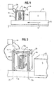
- FIG. 3 there is shown a cross-sectional view of an exemplary air knife 18.
- One of the novel features of the present positive air system 12 is the ability to maintain the "cleanliness" of the environment enveloping the print head; that is, the area between the print head and the boundaries defined by the air knives 18a,b,c, e.g., the local environment E.
- the present positive air system 12 controls this environment, i.e., maintains a positive pressure to reduce or eliminate the ingress of dust and debris, while at the same time, preventing interference with the fluid jetting patterns.
- An air path 28 is formed in each knife 18 that branches from a main or common branch 30 to each of the orifices 22.
- the path 28 is configured such that the pressure drop (or the ultimate pressure) at each orifice 22 is equal to the pressure at each other orifice 22. In this manner, there are no unaccounted for, or undetermined, air flow patterns. Rather, by balancing the pressure drop, the air flow pattern is predictable so as to prevent interference with the fluid jet pattern.
- the primary branch 30 is divided into three secondary branches 32.
- Each of the secondary branches 32 is further divided into three tertiary branches 34 which in turn are divided into paired orifice feed branches 36.
- Each of the orifice feed branches 36 is about the same length as each other orifice feed branch 36. As such, the pressure drop across each of the orifice feed branches 36 is about equal as well. However, the secondary 32 and tertiary branches 34 are not of equal length; thus, the pressure drop could differ between branches (that is among the secondary branches 32 or among the tertiary branches 34). In order to assure that the pressure drop across each of the branches 32, 34 is about equal, a diverter 38 is positioned at about the branch 32 or 34 junctures. In this manner, the diverter directs or diverts air flow into the various branches 32 and 34 to effect an equal pressure drop (and thus outlet pressure) at each of the orifices 2.
- a pin 40 can be positioned at the entrance to each of the shortest of the secondary 32 and tertiary 34 branches. The pin 40 further assists in balancing the pressure drops through the various branches to effect a balanced pressure at the orifices 22.
- a restrictor such as that indicated at 42, can be positioned at about each of the orifices 22.
- the restrictor 42 is configured so as to assist in effecting an equal pressure drop (e.g., equal pressure at the orifices), and to further limit the velocity and pressure of the air exiting the orifices.
- the present system 12 uses air at a pressure of about 0.07 bar (1 psig) to about 0.3 bar (5 psig). It has been found that an air pressure of about 0.07 (1 psig) is advantageous over known high pressure systems in that the air pressure is sufficiently low so that there is little to no adverse effect on the jetted fluid. That is, the air does not move the jetted fluid from the path that the fluid would other traverse toward the media (e.g., box B) onto which it is applied.
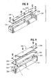
- FIG. 4 An alternate embodiment of an air path 128 for an air knife 1 is shown in Figure 4 .
- the path 128 includes a main or primary branch 128 that divides into three secondary branches 132.
- Each of the three secondary branches 132 in turn divides into three tertiary branches 134 which in turn divide into three orifice feed branches 136.
- pins 140, diverters 138 and restrictors 142 can be used (if desired) to facilitate the balancing or equalizing or air pressure at each of the orifices 122.
- a restriction 144 (as a decrease in diameter or a restrictor can be formed at about the primary branch 130 to further facilitate pressure balancing.
- the orifices 122a at about the edge of the knife 118 can be angled outward. In this manner (because the knives 118 are angled outward and/or upward relative to the print head 10, as best seen in Figure 10-13 ), any gaps in air flow that may otherwise occur at the "corners" where the upper and side knives meet, are "filled".
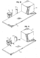
- FIG. 6 and 7 Another embodiment of the air knife or air curtain is shown in Figures 6 and 7 .
- a relatively large, contained chamber 220 provides a pressurized air reservoir 223. Air is direct out of the reservoir 223 through a plurality of small orifice-like openings 222 in the body of the chamber 220 ( Figure 6 ).
- air is directed through an elongated, narrow orifice-like slot 228 in the chamber 220 or in a cover plate 226 ( Figure 8 ) for the chamber 220, overlying the reservoir 223
- a thin spacer plate 330 (about 1/1000 inch or 25 ⁇ m) having a notched or etched portion 332 is positioned between the chamber body 320 and the cover plate 326.
- the notch 332 is open to the reservoir 323 so that air exits the reservoir 323 from between the chamber body 320 and the cover plate 326 through the an elongated orifice-like slot 322 that is defined by the notch 332.
- This arrangement provides a continuous restricted flow path or continuous restriction, and as such, provides for a controlled flow (and pressure) along the length of the slot 322.
- FIG. 7 An exemplary cross-section of the air knife embodiment 218 of Figure 6 is illustrated in Figure 7 .
- an entrance 234, 334 to the reservoir 223, 323, formed in the chamber body 220, 320 is relatively small (thus defining a restriction) compared to the size of the reservoir 223, 323.
- the pressure drop at any of the orifices 222 is about equal to the pressure drop at any of the other orifices 222 and, likewise, the pressure drop at any location along the elongated slot 228, 322 is about equal to the pressure drop at any other location along the slot 228, 322.
- the spacer plate 330 of the comparative embodiment 318 can have an angled edge (as indicated at 333) to direct air outwardly, at an angle, to account for the angled orientation of the knives 318. This prevents "gaps" at the corners or junctures of the upper and side knives 318.
- the present positive air system 12 uses angled curtains or knives 18 to facilitate directing the deflected air away (indicated by the arrow at 44 in Figure 13 ) from the print head 10. That is, rather than the orifices 22, 122, 222 directing air perpendicular to the box surface S onto which the indicia is printed, the orifices 22, 122, 222 direct the air at an angle relative to the surface S. In this manner, the air that deflects off of the surface S is directed away from the print head 10, rather than toward the print head 10. It has been observed that this arrangement blows the dust and debris away from the local environment E to maintain the print head 10 and environment E contaminant free. This arrangement also prevents the formation of eddy currents within the local environment E (e.g., immediately around the print head 10), that could otherwise adversely impact the fluid droplet path.
- the positive air system 12 can include a supplemental box cleaner knife 46 positioned upstream of the print head 14) and its associated knives/curtains 18, 118.
- This supplemental knife 46 facilitates maintaining the local environment E contaminant-free by removing any dust or debris that may be present on the box B before the box B is presented at the print head 10.
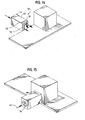
- FIG. 14-16 A further comparative embodiment of positive air system 50 which does not form part of this invention is illustrated in Figures 14-16 .
- the print head 10 is disposed within an enclosure 52 that essentially forms a tunnel 54.
- the air flows through the tunnel 54, including around the print head 10, and out a forward end 56 of the tunnel past the print head 10.
- a flapper valve 58 is positioned in one of the enclosure walls 60 that provides communication between the tunnel 54 and the outside environment.
- the flapper valve 58 is closed during normal operation, thus isolating all but the tunnel front 56.
- the flapper valve 58 opens to relieve any pressure increase in the tunnel 54. In this manner, the air that is supplied through the tunnel 4 does not adversely effect the operation of the print head 10 (i.e., effect the fluid droplet path). Again, air is supplied from a clean, debris-free air supply 62.
Landscapes
- Ink Jet (AREA)
- Particle Formation And Scattering Control In Inkjet Printers (AREA)
Applications Claiming Priority (2)
| Application Number | Priority Date | Filing Date | Title |
|---|---|---|---|
| US401882 | 1999-09-23 | ||
| US10/401,822 US6890053B2 (en) | 2003-03-28 | 2003-03-28 | Positive air system for inkjet print head |
Publications (3)
| Publication Number | Publication Date |
|---|---|
| EP1462256A2 EP1462256A2 (en) | 2004-09-29 |
| EP1462256A3 EP1462256A3 (en) | 2004-11-24 |
| EP1462256B1 true EP1462256B1 (en) | 2009-05-13 |
Family
ID=32850554
Family Applications (1)
| Application Number | Title | Priority Date | Filing Date |
|---|---|---|---|
| EP04251479A Expired - Lifetime EP1462256B1 (en) | 2003-03-28 | 2004-03-15 | Positive pressure air system for inkjet print head |
Country Status (6)
| Country | Link |
|---|---|
| US (1) | US6890053B2 (enExample) |
| EP (1) | EP1462256B1 (enExample) |
| JP (1) | JP2004299398A (enExample) |
| AT (1) | ATE431251T1 (enExample) |
| CA (1) | CA2455674C (enExample) |
| IL (1) | IL161101A (enExample) |
Families Citing this family (28)
| Publication number | Priority date | Publication date | Assignee | Title |
|---|---|---|---|---|
| US6997539B2 (en) * | 2003-06-13 | 2006-02-14 | Dimatix, Inc. | Apparatus for depositing droplets |
| US20050099451A1 (en) * | 2003-11-04 | 2005-05-12 | Videojet Technologies Inc. | Method and apparatus for reducing debris accumulation in an ink jet printhead |
| CN101094768A (zh) * | 2004-12-03 | 2007-12-26 | 富士胶卷迪马蒂克斯股份有限公司 | 打印头和使用打印头的系统 |
| JP2007117959A (ja) * | 2005-10-31 | 2007-05-17 | Kubota Matsushitadenko Exterior Works Ltd | 建築板の塗装装置 |
| US7520588B2 (en) * | 2005-12-23 | 2009-04-21 | Xerox Corp | Apparatus for reducing ink jet contamination |
| US7918530B2 (en) * | 2006-02-03 | 2011-04-05 | Rr Donnelley | Apparatus and method for cleaning an inkjet printhead |
| JP4201033B2 (ja) * | 2006-07-31 | 2008-12-24 | ブラザー工業株式会社 | インクジェット記録装置 |
| US8079698B2 (en) * | 2006-07-31 | 2011-12-20 | Brother Kogyo Kabushiki Kaisha | Inkjet recording apparatus |
| US7571996B2 (en) * | 2006-08-10 | 2009-08-11 | Xerox Corporation | Apparatus for reducing particulate in an ink jet printer |
| FR2913632A1 (fr) * | 2007-03-14 | 2008-09-19 | Imaje Sa Sa | Dispositif d'impression a jet d'encre a injecteur d'air, injecteur d'air et tete d'impression grande largeur associes |
| JP4591463B2 (ja) * | 2007-03-26 | 2010-12-01 | ブラザー工業株式会社 | 液体吐出装置 |
| US20090021542A1 (en) * | 2007-06-29 | 2009-01-22 | Kanfoush Dan E | System and method for fluid transmission and temperature regulation in an inkjet printing system |
| FR2934809A1 (fr) * | 2008-08-11 | 2010-02-12 | Imaje Sa | Dispositif d'impression a jet d'encre a injecteur d'air, injecteur d'air et tete d'impression grande largeur associes |
| FR2934810A1 (fr) * | 2008-08-11 | 2010-02-12 | Imaje Sa | Dispositif d'impression a jet d'encre a compensation de vitesse de jet |
| CN102325655B (zh) * | 2009-02-18 | 2014-11-05 | 录象射流技术公司 | 打印头组件和操作打印头的方法 |
| JP5663253B2 (ja) * | 2010-09-28 | 2015-02-04 | ユニ・チャーム株式会社 | 吸収性物品に係る接着剤塗布装置、及び接着剤塗布方法 |
| US8529015B2 (en) | 2012-02-02 | 2013-09-10 | Xerox Corporation | Apparatus and method for removal of ink from an exterior of a printhead |
| EP2822771B1 (en) | 2012-03-09 | 2019-07-17 | R. R. Donnelley & Sons Company | System and method for cleaning inkjet cartridges |
| WO2013147893A1 (en) | 2012-03-30 | 2013-10-03 | Hewlett-Packard Development Company, L.P. | Recirculate and filter air to form air barrier in image forming apparatus |
| US8888208B2 (en) | 2012-04-27 | 2014-11-18 | R.R. Donnelley & Sons Company | System and method for removing air from an inkjet cartridge and an ink supply line |
| US8727485B2 (en) | 2012-05-14 | 2014-05-20 | Xerox Corporation | Three position printhead wiper assembly |
| US8985731B2 (en) * | 2012-05-18 | 2015-03-24 | Brother Kogyo Kabushiki Kaisha | Liquid ejection apparatuses |
| US9216581B2 (en) | 2013-02-08 | 2015-12-22 | R.R. Donnelley & Sons Company | Apparatus and method for wiping an inkjet cartridge nozzle plate |
| CN108778753B (zh) | 2016-03-04 | 2020-04-21 | R.R.当纳利父子公司 | 打印头维护台及其操作方法 |
| US10124597B2 (en) | 2016-05-09 | 2018-11-13 | R.R. Donnelley & Sons Company | System and method for supplying ink to an inkjet printhead |
| JP2020128052A (ja) * | 2019-02-12 | 2020-08-27 | 三菱重工業株式会社 | インクジェット塗装用の排気装置、インクジェット吐出装置、インクジェット塗装方法、および部材の製造方法 |
| EP3956144B1 (en) | 2019-04-19 | 2024-08-28 | Markem-Imaje Corporation | Purged ink removal from print head |
| US11186086B2 (en) | 2019-04-19 | 2021-11-30 | Markem-Imaje Corporation | Systems and techniques to reduce debris buildup around print head nozzles |
Family Cites Families (27)
| Publication number | Priority date | Publication date | Assignee | Title |
|---|---|---|---|---|
| DE2439144C3 (de) * | 1974-08-14 | 1979-04-05 | Siemens Ag, 1000 Berlin Und 8000 Muenchen | Vorrichtung zum Verteilen strömender Medien von einem Strömungsquerschnitt auf einen davon verschiedenen Strömungsquerschnitt |
| JPS5830691Y2 (ja) * | 1976-05-12 | 1983-07-06 | ミノルタ株式会社 | インクジエツト記録装置 |
| JPS55146774A (en) | 1979-05-04 | 1980-11-15 | Nec Corp | Ink-jet recording device |
| JPS5638268A (en) | 1979-09-05 | 1981-04-13 | Ricoh Co Ltd | Ink jet recorder |
| JPS5638267A (en) | 1979-09-05 | 1981-04-13 | Ricoh Co Ltd | Ink jet recorder |
| JPS56161854A (en) * | 1980-05-15 | 1981-12-12 | Matsushita Electric Works Ltd | Spray head for spraying resin |
| US4411706A (en) * | 1981-06-25 | 1983-10-25 | Burroughs Corporation | Method and apparatus for eliminating dust from ink jet printers |
| US4418355A (en) * | 1982-01-04 | 1983-11-29 | Exxon Research And Engineering Co. | Ink jet apparatus with preloaded diaphragm and method of making same |
| JPS59158930A (ja) * | 1983-02-28 | 1984-09-08 | Kurifu Kk | 圧力調整ダンパ |
| JPS61164838A (ja) | 1985-01-18 | 1986-07-25 | Nec Corp | インクジエツトヘツド |
| US4591869A (en) | 1985-04-12 | 1986-05-27 | Eastman Kodak Company | Ink jet printing apparatus and method providing an induced, clean-air region |
| EP0285831B1 (de) * | 1987-03-20 | 1991-06-05 | Siemens Aktiengesellschaft | Rückwandleiterplatte |
| US4875054A (en) | 1987-05-27 | 1989-10-17 | Burlington Industries, Inc. | Clean air hood for fluid jet printing |
| JPS6426007A (en) * | 1987-11-06 | 1989-01-27 | Matsushita Electric Industrial Co Ltd | Controller for fluid flow direction |
| JPH01152762U (enExample) * | 1988-04-08 | 1989-10-20 | ||
| JPH04334455A (ja) | 1991-05-10 | 1992-11-20 | Hitachi Ltd | インクジェットプリンタ |
| US5173988A (en) * | 1991-06-17 | 1992-12-29 | Videojet Systems International, Inc. | Dewatering apparatus for drop marking bottles and cans |
| JPH0775694B2 (ja) * | 1991-09-11 | 1995-08-16 | ナショナル住宅産業株式会社 | 塗布用ノズル |
| US5519420A (en) * | 1992-12-21 | 1996-05-21 | Ncr Corporation | Air system to protect ink jet head |
| US5355910A (en) * | 1993-10-13 | 1994-10-18 | Trw Inc. | Dual component flap |
| JPH11114473A (ja) * | 1997-10-17 | 1999-04-27 | Kichishiro Ota | 断熱パネルの製造方法および装置 |
| JPH11290746A (ja) * | 1998-04-07 | 1999-10-26 | Musashi Eng Co Ltd | 流体の吐出路構造 |
| DE20122940U1 (de) | 2000-09-11 | 2011-02-17 | Zipher Ltd. | Druckvorrichtung |
| WO2002036347A2 (en) | 2000-10-31 | 2002-05-10 | Zipher Limited | Printing apparatus |
| GB2370249A (en) | 2000-11-04 | 2002-06-26 | Zipher | Method of printing an image onto a low contrast substrate |
| US20020089563A1 (en) | 2001-01-10 | 2002-07-11 | Shigeaki Tanaka | Liquid-ejection recording head and ink-jet recorder |
| US6491364B2 (en) * | 2001-04-27 | 2002-12-10 | Hewlett-Packard Company | Inkjet printing with air movement system to improve dot shape |
-
2003
- 2003-03-28 US US10/401,822 patent/US6890053B2/en not_active Expired - Lifetime
-
2004
- 2004-01-22 CA CA002455674A patent/CA2455674C/en not_active Expired - Fee Related
- 2004-03-15 EP EP04251479A patent/EP1462256B1/en not_active Expired - Lifetime
- 2004-03-15 AT AT04251479T patent/ATE431251T1/de not_active IP Right Cessation
- 2004-03-25 IL IL161101A patent/IL161101A/en not_active IP Right Cessation
- 2004-03-29 JP JP2004095832A patent/JP2004299398A/ja active Pending
Also Published As
| Publication number | Publication date |
|---|---|
| US20040189744A1 (en) | 2004-09-30 |
| US6890053B2 (en) | 2005-05-10 |
| CA2455674C (en) | 2008-04-01 |
| IL161101A0 (en) | 2004-08-31 |
| JP2004299398A (ja) | 2004-10-28 |
| ATE431251T1 (de) | 2009-05-15 |
| CA2455674A1 (en) | 2004-09-28 |
| EP1462256A2 (en) | 2004-09-29 |
| EP1462256A3 (en) | 2004-11-24 |
| IL161101A (en) | 2006-10-05 |
Similar Documents
| Publication | Publication Date | Title |
|---|---|---|
| EP1462256B1 (en) | Positive pressure air system for inkjet print head | |
| EP1319510B1 (en) | Inkjet drop selection in a non-uniform airstream | |
| EP2142372B1 (en) | Printer having improved gas flow drop deflection | |
| US7862147B2 (en) | Inclined feature to protect printhead face | |
| US4591869A (en) | Ink jet printing apparatus and method providing an induced, clean-air region | |
| US8573736B2 (en) | Inkjet printer, inkjet head, and printing method | |
| CN102333655B (zh) | 喷墨印刷机、喷墨头、以及印刷方法 | |
| US20090073215A1 (en) | Printheads and systems using printheads | |
| US7967423B2 (en) | Pressure modulation cleaning of jetting module nozzles | |
| JP5702950B2 (ja) | 液滴吐出装置 | |
| WO2005044563A3 (en) | Method and apparatus for reducing debris accumulation in an ink jet printhead | |
| US6572223B2 (en) | Apparatus and method of balancing end jet forces in an ink jet printing system | |
| JP2011079274A (ja) | インクジェットプリンタ、インクジェットヘッド、及び印刷方法 | |
| JP2008137158A (ja) | 画像形成装置 | |
| US8091992B2 (en) | Deflection device including gas flow restriction device | |
| CN100519193C (zh) | 减小喷墨打印头中碎片积累的方法和设备 | |
| US9505220B1 (en) | Catcher for collecting ink from non-printed drops | |
| WO2021070513A1 (ja) | インクジェット記録装置 | |
| HK1099735A (en) | Method and apparatus for reducing debris accumulation in an ink jet printhead | |
| WO2014164166A1 (en) | Printhead including coanda catcher with grooved radius |
Legal Events
| Date | Code | Title | Description |
|---|---|---|---|
| PUAI | Public reference made under article 153(3) epc to a published international application that has entered the european phase |
Free format text: ORIGINAL CODE: 0009012 |
|
| AK | Designated contracting states |
Kind code of ref document: A2 Designated state(s): AT BE BG CH CY CZ DE DK EE ES FI FR GB GR HU IE IT LI LU MC NL PL PT RO SE SI SK TR |
|
| AX | Request for extension of the european patent |
Extension state: AL LT LV MK |
|
| PUAL | Search report despatched |
Free format text: ORIGINAL CODE: 0009013 |
|
| AK | Designated contracting states |
Kind code of ref document: A3 Designated state(s): AT BE BG CH CY CZ DE DK EE ES FI FR GB GR HU IE IT LI LU MC NL PL PT RO SE SI SK TR |
|
| AX | Request for extension of the european patent |
Extension state: AL LT LV MK |
|
| 17P | Request for examination filed |
Effective date: 20050513 |
|
| AKX | Designation fees paid |
Designated state(s): AT BE BG CH CY CZ DE DK EE ES FI FR GB GR HU IE IT LI LU MC NL PL PT RO SE SI SK TR |
|
| 17Q | First examination report despatched |
Effective date: 20070521 |
|
| GRAP | Despatch of communication of intention to grant a patent |
Free format text: ORIGINAL CODE: EPIDOSNIGR1 |
|
| GRAS | Grant fee paid |
Free format text: ORIGINAL CODE: EPIDOSNIGR3 |
|
| GRAA | (expected) grant |
Free format text: ORIGINAL CODE: 0009210 |
|
| AK | Designated contracting states |
Kind code of ref document: B1 Designated state(s): AT BE BG CH CY CZ DE DK EE ES FI FR GB GR HU IE IT LI LU MC NL PL PT RO SE SI SK TR |
|
| REG | Reference to a national code |
Ref country code: GB Ref legal event code: FG4D |
|
| REG | Reference to a national code |
Ref country code: CH Ref legal event code: EP |
|
| REG | Reference to a national code |
Ref country code: IE Ref legal event code: FG4D |
|
| REF | Corresponds to: |
Ref document number: 602004021057 Country of ref document: DE Date of ref document: 20090625 Kind code of ref document: P |
|
| PG25 | Lapsed in a contracting state [announced via postgrant information from national office to epo] |
Ref country code: ES Free format text: LAPSE BECAUSE OF FAILURE TO SUBMIT A TRANSLATION OF THE DESCRIPTION OR TO PAY THE FEE WITHIN THE PRESCRIBED TIME-LIMIT Effective date: 20090824 Ref country code: FI Free format text: LAPSE BECAUSE OF FAILURE TO SUBMIT A TRANSLATION OF THE DESCRIPTION OR TO PAY THE FEE WITHIN THE PRESCRIBED TIME-LIMIT Effective date: 20090513 Ref country code: AT Free format text: LAPSE BECAUSE OF FAILURE TO SUBMIT A TRANSLATION OF THE DESCRIPTION OR TO PAY THE FEE WITHIN THE PRESCRIBED TIME-LIMIT Effective date: 20090513 Ref country code: PT Free format text: LAPSE BECAUSE OF FAILURE TO SUBMIT A TRANSLATION OF THE DESCRIPTION OR TO PAY THE FEE WITHIN THE PRESCRIBED TIME-LIMIT Effective date: 20090913 |
|
| NLV1 | Nl: lapsed or annulled due to failure to fulfill the requirements of art. 29p and 29m of the patents act | ||
| PG25 | Lapsed in a contracting state [announced via postgrant information from national office to epo] |
Ref country code: PL Free format text: LAPSE BECAUSE OF FAILURE TO SUBMIT A TRANSLATION OF THE DESCRIPTION OR TO PAY THE FEE WITHIN THE PRESCRIBED TIME-LIMIT Effective date: 20090513 Ref country code: SI Free format text: LAPSE BECAUSE OF FAILURE TO SUBMIT A TRANSLATION OF THE DESCRIPTION OR TO PAY THE FEE WITHIN THE PRESCRIBED TIME-LIMIT Effective date: 20090513 Ref country code: NL Free format text: LAPSE BECAUSE OF FAILURE TO SUBMIT A TRANSLATION OF THE DESCRIPTION OR TO PAY THE FEE WITHIN THE PRESCRIBED TIME-LIMIT Effective date: 20090513 Ref country code: SE Free format text: LAPSE BECAUSE OF FAILURE TO SUBMIT A TRANSLATION OF THE DESCRIPTION OR TO PAY THE FEE WITHIN THE PRESCRIBED TIME-LIMIT Effective date: 20090813 |
|
| PG25 | Lapsed in a contracting state [announced via postgrant information from national office to epo] |
Ref country code: RO Free format text: LAPSE BECAUSE OF FAILURE TO SUBMIT A TRANSLATION OF THE DESCRIPTION OR TO PAY THE FEE WITHIN THE PRESCRIBED TIME-LIMIT Effective date: 20090513 Ref country code: EE Free format text: LAPSE BECAUSE OF FAILURE TO SUBMIT A TRANSLATION OF THE DESCRIPTION OR TO PAY THE FEE WITHIN THE PRESCRIBED TIME-LIMIT Effective date: 20090513 Ref country code: DK Free format text: LAPSE BECAUSE OF FAILURE TO SUBMIT A TRANSLATION OF THE DESCRIPTION OR TO PAY THE FEE WITHIN THE PRESCRIBED TIME-LIMIT Effective date: 20090513 Ref country code: CZ Free format text: LAPSE BECAUSE OF FAILURE TO SUBMIT A TRANSLATION OF THE DESCRIPTION OR TO PAY THE FEE WITHIN THE PRESCRIBED TIME-LIMIT Effective date: 20090513 |
|
| PG25 | Lapsed in a contracting state [announced via postgrant information from national office to epo] |
Ref country code: BE Free format text: LAPSE BECAUSE OF FAILURE TO SUBMIT A TRANSLATION OF THE DESCRIPTION OR TO PAY THE FEE WITHIN THE PRESCRIBED TIME-LIMIT Effective date: 20090513 Ref country code: SK Free format text: LAPSE BECAUSE OF FAILURE TO SUBMIT A TRANSLATION OF THE DESCRIPTION OR TO PAY THE FEE WITHIN THE PRESCRIBED TIME-LIMIT Effective date: 20090513 |
|
| PLBE | No opposition filed within time limit |
Free format text: ORIGINAL CODE: 0009261 |
|
| STAA | Information on the status of an ep patent application or granted ep patent |
Free format text: STATUS: NO OPPOSITION FILED WITHIN TIME LIMIT |
|
| PG25 | Lapsed in a contracting state [announced via postgrant information from national office to epo] |
Ref country code: BG Free format text: LAPSE BECAUSE OF FAILURE TO SUBMIT A TRANSLATION OF THE DESCRIPTION OR TO PAY THE FEE WITHIN THE PRESCRIBED TIME-LIMIT Effective date: 20090813 |
|
| 26N | No opposition filed |
Effective date: 20100216 |
|
| PG25 | Lapsed in a contracting state [announced via postgrant information from national office to epo] |
Ref country code: GR Free format text: LAPSE BECAUSE OF FAILURE TO SUBMIT A TRANSLATION OF THE DESCRIPTION OR TO PAY THE FEE WITHIN THE PRESCRIBED TIME-LIMIT Effective date: 20090814 Ref country code: MC Free format text: LAPSE BECAUSE OF NON-PAYMENT OF DUE FEES Effective date: 20100331 |
|
| REG | Reference to a national code |
Ref country code: CH Ref legal event code: PL |
|
| GBPC | Gb: european patent ceased through non-payment of renewal fee |
Effective date: 20100315 |
|
| REG | Reference to a national code |
Ref country code: FR Ref legal event code: ST Effective date: 20101130 |
|
| PG25 | Lapsed in a contracting state [announced via postgrant information from national office to epo] |
Ref country code: FR Free format text: LAPSE BECAUSE OF NON-PAYMENT OF DUE FEES Effective date: 20100331 Ref country code: IE Free format text: LAPSE BECAUSE OF NON-PAYMENT OF DUE FEES Effective date: 20100315 |
|
| PG25 | Lapsed in a contracting state [announced via postgrant information from national office to epo] |
Ref country code: CH Free format text: LAPSE BECAUSE OF NON-PAYMENT OF DUE FEES Effective date: 20100331 Ref country code: LI Free format text: LAPSE BECAUSE OF NON-PAYMENT OF DUE FEES Effective date: 20100331 Ref country code: DE Free format text: LAPSE BECAUSE OF NON-PAYMENT OF DUE FEES Effective date: 20101001 |
|
| PG25 | Lapsed in a contracting state [announced via postgrant information from national office to epo] |
Ref country code: GB Free format text: LAPSE BECAUSE OF NON-PAYMENT OF DUE FEES Effective date: 20100315 Ref country code: IT Free format text: LAPSE BECAUSE OF FAILURE TO SUBMIT A TRANSLATION OF THE DESCRIPTION OR TO PAY THE FEE WITHIN THE PRESCRIBED TIME-LIMIT Effective date: 20090513 |
|
| PG25 | Lapsed in a contracting state [announced via postgrant information from national office to epo] |
Ref country code: CY Free format text: LAPSE BECAUSE OF FAILURE TO SUBMIT A TRANSLATION OF THE DESCRIPTION OR TO PAY THE FEE WITHIN THE PRESCRIBED TIME-LIMIT Effective date: 20090513 |
|
| PG25 | Lapsed in a contracting state [announced via postgrant information from national office to epo] |
Ref country code: HU Free format text: LAPSE BECAUSE OF FAILURE TO SUBMIT A TRANSLATION OF THE DESCRIPTION OR TO PAY THE FEE WITHIN THE PRESCRIBED TIME-LIMIT Effective date: 20091114 Ref country code: LU Free format text: LAPSE BECAUSE OF NON-PAYMENT OF DUE FEES Effective date: 20100315 |
|
| PG25 | Lapsed in a contracting state [announced via postgrant information from national office to epo] |
Ref country code: TR Free format text: LAPSE BECAUSE OF FAILURE TO SUBMIT A TRANSLATION OF THE DESCRIPTION OR TO PAY THE FEE WITHIN THE PRESCRIBED TIME-LIMIT Effective date: 20090513 |