EP1460733B1 - Conductor rail adapter - Google Patents
Conductor rail adapter Download PDFInfo
- Publication number
- EP1460733B1 EP1460733B1 EP04006280A EP04006280A EP1460733B1 EP 1460733 B1 EP1460733 B1 EP 1460733B1 EP 04006280 A EP04006280 A EP 04006280A EP 04006280 A EP04006280 A EP 04006280A EP 1460733 B1 EP1460733 B1 EP 1460733B1
- Authority
- EP
- European Patent Office
- Prior art keywords
- snap
- organ
- shell part
- housing
- operating shaft
- Prior art date
- Legal status (The legal status is an assumption and is not a legal conclusion. Google has not performed a legal analysis and makes no representation as to the accuracy of the status listed.)
- Expired - Lifetime
Links
- 239000004020 conductor Substances 0.000 title claims description 22
- 210000000056 organ Anatomy 0.000 claims 11
- 239000011810 insulating material Substances 0.000 claims 1
- 229920002994 synthetic fiber Polymers 0.000 claims 1
- 229920003023 plastic Polymers 0.000 abstract description 2
- 239000004033 plastic Substances 0.000 abstract description 2
- 239000000463 material Substances 0.000 abstract 1
- 210000002105 tongue Anatomy 0.000 description 26
- 238000003780 insertion Methods 0.000 description 9
- 230000037431 insertion Effects 0.000 description 9
- 230000007935 neutral effect Effects 0.000 description 9
- RYGMFSIKBFXOCR-UHFFFAOYSA-N Copper Chemical compound [Cu] RYGMFSIKBFXOCR-UHFFFAOYSA-N 0.000 description 2
- 238000005452 bending Methods 0.000 description 2
- 230000000903 blocking effect Effects 0.000 description 2
- 238000010276 construction Methods 0.000 description 2
- 229910052802 copper Inorganic materials 0.000 description 2
- 239000010949 copper Substances 0.000 description 2
- 238000009434 installation Methods 0.000 description 2
- 230000004308 accommodation Effects 0.000 description 1
- 230000004323 axial length Effects 0.000 description 1
- 230000015572 biosynthetic process Effects 0.000 description 1
- 238000006073 displacement reaction Methods 0.000 description 1
Images


Classifications
-
- H—ELECTRICITY
- H01—ELECTRIC ELEMENTS
- H01R—ELECTRICALLY-CONDUCTIVE CONNECTIONS; STRUCTURAL ASSOCIATIONS OF A PLURALITY OF MUTUALLY-INSULATED ELECTRICAL CONNECTING ELEMENTS; COUPLING DEVICES; CURRENT COLLECTORS
- H01R25/00—Coupling parts adapted for simultaneous co-operation with two or more identical counterparts, e.g. for distributing energy to two or more circuits
- H01R25/14—Rails or bus-bars constructed so that the counterparts can be connected thereto at any point along their length
-
- H—ELECTRICITY
- H01—ELECTRIC ELEMENTS
- H01R—ELECTRICALLY-CONDUCTIVE CONNECTIONS; STRUCTURAL ASSOCIATIONS OF A PLURALITY OF MUTUALLY-INSULATED ELECTRICAL CONNECTING ELEMENTS; COUPLING DEVICES; CURRENT COLLECTORS
- H01R13/00—Details of coupling devices of the kinds covered by groups H01R12/70 or H01R24/00 - H01R33/00
- H01R13/46—Bases; Cases
- H01R13/502—Bases; Cases composed of different pieces
- H01R13/506—Bases; Cases composed of different pieces assembled by snap action of the parts
-
- F—MECHANICAL ENGINEERING; LIGHTING; HEATING; WEAPONS; BLASTING
- F21—LIGHTING
- F21V—FUNCTIONAL FEATURES OR DETAILS OF LIGHTING DEVICES OR SYSTEMS THEREOF; STRUCTURAL COMBINATIONS OF LIGHTING DEVICES WITH OTHER ARTICLES, NOT OTHERWISE PROVIDED FOR
- F21V21/00—Supporting, suspending, or attaching arrangements for lighting devices; Hand grips
- F21V21/34—Supporting elements displaceable along a guiding element
- F21V21/35—Supporting elements displaceable along a guiding element with direct electrical contact between the supporting element and electric conductors running along the guiding element
-
- H—ELECTRICITY
- H01—ELECTRIC ELEMENTS
- H01R—ELECTRICALLY-CONDUCTIVE CONNECTIONS; STRUCTURAL ASSOCIATIONS OF A PLURALITY OF MUTUALLY-INSULATED ELECTRICAL CONNECTING ELEMENTS; COUPLING DEVICES; CURRENT COLLECTORS
- H01R13/00—Details of coupling devices of the kinds covered by groups H01R12/70 or H01R24/00 - H01R33/00
- H01R13/46—Bases; Cases
- H01R13/50—Bases; Cases formed as an integral body
- H01R13/501—Bases; Cases formed as an integral body comprising an integral hinge or a frangible part
-
- H—ELECTRICITY
- H01—ELECTRIC ELEMENTS
- H01R—ELECTRICALLY-CONDUCTIVE CONNECTIONS; STRUCTURAL ASSOCIATIONS OF A PLURALITY OF MUTUALLY-INSULATED ELECTRICAL CONNECTING ELEMENTS; COUPLING DEVICES; CURRENT COLLECTORS
- H01R31/00—Coupling parts supported only by co-operation with counterpart
- H01R31/06—Intermediate parts for linking two coupling parts, e.g. adapter
-
- Y—GENERAL TAGGING OF NEW TECHNOLOGICAL DEVELOPMENTS; GENERAL TAGGING OF CROSS-SECTIONAL TECHNOLOGIES SPANNING OVER SEVERAL SECTIONS OF THE IPC; TECHNICAL SUBJECTS COVERED BY FORMER USPC CROSS-REFERENCE ART COLLECTIONS [XRACs] AND DIGESTS
- Y10—TECHNICAL SUBJECTS COVERED BY FORMER USPC
- Y10S—TECHNICAL SUBJECTS COVERED BY FORMER USPC CROSS-REFERENCE ART COLLECTIONS [XRACs] AND DIGESTS
- Y10S439/00—Electrical connectors
- Y10S439/901—Connector hood or shell
- Y10S439/904—Multipart shell
- Y10S439/906—Longitudinally divided
Definitions
- the invention relates to a device for the at least indirect connection of a lamp with a busbar according to the preamble of claim 1.
- a device for the at least indirect connection of a luminaire to a busbar is commonly referred to as a busbar adapter.
- a busbar In a busbar, a plurality of lights, axially displaceable, can be fastened in a simple manner.
- a busbar adapter of the prior art, which is due to the applicant, is in the DE 28 10 681 A1 described.
- the adapter known from this is manufactured almost unchanged by the applicant for 25 years now.
- the known busbar adapter consists of a variety of items and requires a complex assembly.
- the housing consists of three housing shell parts, which are held together by means of conventional threaded screws.
- the first shift shaft is pivotable through a 90 ° angle and has a pair of retaining tabs and a neutral contact tongue.
- the second switching shaft is pivotable through 180 ° and in particular has a phase conductor contact tongue.
- a locking member G is arranged, which in the form of a mutual control ensures that no incorrect operation occurs.
- the object of the invention is that of the DE 28 10 681 A1 known busbar adapter according to the preamble of claim 1 such that a simpler installation is possible.
- the invention solves this problem with the features of claim 1, in particular with those of the characterizing part and is accordingly characterized in that at least one first housing shell part a locking member is arranged, which cooperates with the switching shaft and / or with a second housing shell part.
- the principle of the invention is thus essentially to provide locking members, which may be formed, for example, in the manner of clip elements and exercise a holding function.
- latching members of the first kind which are arranged on a first housing shell part and which cooperate with corresponding retaining surfaces on another housing shell part.
- latching members of the first kind which are arranged on a first housing shell part and which cooperate with corresponding retaining surfaces on another housing shell part.
- the locking members may be formed in the manner of snap connection elements that can automatically snap in an automatic movement of a housing shell part relative to the other.
- the locking members may also be provided to cooperate with the shift shaft.
- the busbar adapter both from its external structure, as well as in terms of its internal parts and its functions from the DE 28 10 681 A1 known busbar adapter almost completely corresponds, has a first and a second switching shaft, which are pivotally mounted in the housing.
- the first and the second switching shaft for their assembly are only loosely, successively, inserted into the first housing shell. Subsequently, further elements, in particular the locking member, are introduced into the interior of the housing. Finally, connecting conductors that are used for electrical connection with a luminaire are fastened to the corresponding connection terminals. Since the two switching shafts were only loosely inserted, such an attachment designed partially tedious.
- a precisely defined locking seat for the first and / or for the second control shaft by providing at least one locking member.
- a well-defined detent position can be displayed to the user by a sound, which occurs when clips, and then when the proper detent position is reached.
- the switching shaft located in the locking position may preferably be pivotable, so that the locking members in no way affect the switching shaft in their switching function.
- the locking position optionally also allows a z.
- the locking seat for the switching shaft cooperates with an axial securing for the switching shaft, so that a connection conductor for a light can be easily connected by making a connector by moving the free end of the connecting conductor in the axial direction with a corresponding terminal contact in the switching shaft.
- a first type of locking member is provided, which cooperates with the shift shaft and a second type of locking member provided, which cooperates with the second housing shell part.
- the assembly is further facilitated.
- the locking member is integrally formed cohesively to the housing shell part.
- the latching element can be injection-molded, so that the production outlay of the latching element is minimized.
- the locking member is resilient. This allows a particularly simple construction, which can be dispensed with additional items.
- the locking member is designed as a spring tongue.
- the spring tongue protrudes freely from a bottom wall of the housing shell part. Due to the axial length of the spring tongue, the desired elasticity of the locking member can be readily adjusted.
- the housing consists essentially of two housing halves, which are connected to each other via a film hinge.
- the one-piece housing can also be mechanically transferred by pivoting the two housing halves relative to each other in the closed, assembled state.
- a plurality of locking members on the first housing half cooperate with corresponding retaining surfaces on the second housing half.
- the retaining surfaces are arranged in the region of openings in the wall of the housing shell part. This allows a particularly efficient and material-saving accommodation of retaining surfaces and locking members. In addition, in this way, the locking members are accessible from outside even in the assembled state of the housing and can be attacked for example for opening the housing with a loose tool.
- a locking member of the first kind engages around the switching shaft, in particular an outer circumferential surface of the switching shaft, at least partially. This embodiment of the invention ensures a particularly simple securing of the switching shaft to the housing shell part.
- At least one pair of locking members of the first kind is provided, which clasps the shift shaft.
- an optimal power distribution is achieved in a particularly simple manner.
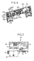
- the device designated in the figures in its entirety by 10 is used to connect a lamp, not shown, to a conventional, in Fig. 1 with the reference numeral 11 designated busbar.
- a bus bar is on the building side, in particular on the ceiling side, mounted and serves to accommodate a Insertion section 12 ( Fig. 2 )
- the device 10 corresponds in its outer dimensions, and from its structural internal structure forth, at least as far as its functionalities, largely in the DE 28 10 681 A1 described there as a busbar adapter designated device of the applicant.
- the busbar 11 has an insertion opening 13, which serves to receive the insertion section 12 of the device 10.
- the device 10 is inserted so far into the insertion opening 13, until a stop surface 14 of the device 10 comes to rest on the underside 15 of the busbar 11 or at least in their area.
- a coding groove 16 is arranged on the busbar 11, in the coding 17, which are mounted in the region of the stop surface 14 on the device 10, can penetrate.
- the busbar 11 has a multiplicity of channels 18a, 18b, 18c, 18d, 18e, 18f, which are designed as holders (for example, 18a, 18f) or as contact channels. In the grooves 18b, 18c, 18d, 18e ladder rails are arranged.
- the conductor rail 19 is designed as a neutral conductor rail, and the remaining three conductor rails are phase conductor rails 20a, 20b, 20c, as is common in the prior art.
- the device 10 is used for electrical contacting and usually also for mechanical attachment of a lamp, not shown in the figures on the busbar 11.
- a Screw connection made in the mounting portion 37 of the device 10, for example by screwing or bracing a fastening element, not shown, of the lamp. It is also known to attach to the attachment portion 37 of the device 10 separate fastening devices, in the manner of holders.
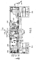
- a first shift shaft 21 (FIG. Fig. 3 ) and a second shift shaft 22 are arranged.
- Each of the two switching shafts 21, 22 is pivotable about its own pivot axis 23.
- the first switching shaft 21 is pivotable about 90 °, and for this purpose has an out of the outer dimensions of a housing 38 also projecting actuating lever 34 which can be manually operated.
- the second switching shaft 22 which is pivotable substantially over a circumferential angular range of 180 °, are at the respect Fig. 3 lower end gripping ridges 25 provided in the manner of an external toothing, which allow easy manual attack.
- a locking member 39 is located according to Fig. 3 approximately midway between the two switching shafts 21, 22 and provides for mutual control.
- the first shift shaft 21 has a neutral contact tongue 26, which projects radially outward with respect to the pivot axis 23 of the shift shaft 21.
- two of the mechanical support serving retaining tongues 27a, 27b are provided.
- the first shift shaft 21 has a head portion 29, a middle portion 30 and a foot portion 31. Head and middle section have a substantially identical outer diameter, wherein the outer diameter of the foot portion 30, however, greatly increased. Overall, the first shift shaft 21 is formed as a hollow body and has central openings 40a, 40b.
- the neutral contact tongue 26 is part of a contact carrier 32, which is formed for example as a stamped part of a copper sheet by bending. At his re Fig. 11 lower end, the contact carrier 32 has a tongue 33, which serves the connection with a tab sleeve of a light side, not shown connecting conductor.
- the second shift shaft 22 has a phase conductor contact tongue 28, which projects in a similar manner as in the switching shaft 21 from the pivot axis 23 radially outwardly away.
- the phase conductor contact tongue 28 is a component of a contact carrier 32, which may also be formed as a copper sheet stamped part.
- the contact carrier 32 of the second switching shaft 22 is located in a chamber-like space 41 and has a mounting portion 42, by means of which the contact carrier 32 is fixed.
- a tongue 33 has with respect Fig. 13 upwards, and is aligned substantially along the pivot axis 23. The tongue 33 is used for electrical connection with a not shown tabs sleeve of a connecting conductor, not shown.
- the second switching shaft 22 can be divided into a head portion 29 and a central portion 30, which have a much smaller outer diameter compared to a foot portion 31.
- the first shift shaft 21 is equally as the shift shaft 22 prior to insertion of the insertion section 12 into the insertion opening 13 in a non-use position.
- the retaining tongues 27a, 27b and the neutral contact tongue 26 as well as the contact tongue 27 and the phase conductor contact tongue 28 of the second control shaft 22 are arranged in this position within the housing 38.
- the first switching shaft 21 can be pivoted about its longitudinal axis 23 by operating the lever 24 by about 90 °, wherein the retaining tongues 27a, 27b and the neutral contact tongue 26 through slots provided for this purpose 43a, 43b 43c can emerge from the housing 38.
- the retaining tongues 27a, 27b penetrate into the corresponding holders 18a, 18f, whereas the neutral contact tongue 26 enters the corresponding neutral conductor contact channel 18e for contacting the neutral conductor rail 19.
- the first shift shaft 21 thus reaches its use position.
- the re Fig. 3 along the double arrow y axially displaceable locking member 39 can be moved due to an outer circumferential groove, not shown on the first shift shaft 21 now in a position in which it allows pivoting of the second shift shaft 22 from its non-use position out. It should be noted that in the inoperative position located first shift shaft 21, a pivoting of the second shift shaft 22 from its rest position is not possible because the locking member 39 ensures a blocking of this movement.
- the blocking member may be formed, for example, as in the DE 28 10 681 A1 is described.
- the second shift shaft 22 When the second shift shaft 22 is shifted from its non-use position to a use position, three different usage positions can be achieved. Depending on whether starting from the non-use position according to Fig. 3 the second switching shaft 22 is rotated counterclockwise by 90 °, a first or a second use position is achieved in which the phase conductor contact tongue 28 emerges either from an upper housing slot 43 d or from a lower housing slot 43 e. The retaining tongue 27 of the second switching shaft 22 accordingly emerges through the respective other housing slot 43e, 43d.
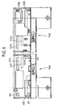
- the housing 38 is, as in particular Fig. 5 becomes clear from two housing halves 34a, 34b, which are formed as half-shells.
- the two housing halves 34a, 34b are connected to each other via a film hinge 44 and thus form a single component.
- the two housing halves 34a, 34b on a bottom wall 35 projecting from a plurality of elements.
- side wall portions 46 a, 46 b, 46 c are provided, which form a pivot bearing for the first shift shaft 21.
- corresponding wall portions 46d, 46e, 46f are provided, which form a pivot bearing for the second switching shaft 22.
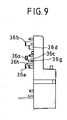
- the peculiarity of the present device 10 is that a plurality of latching members 36a, 36b, 36c, 36d, 36e, 36f, 36g, 36h is provided.
- Each latching member 36a, 36b, 36c, 36d, 36e, 36f, 36g, 36h is formed as a spring tongue element.
- the locking member 36c will be described: This is connected via a mounting portion 47 to the bottom wall 35 of the housing half 34b. An axially elongate portion 48 terminates in a hooked end 49 having a hook surface 50.
- the end 49 is slightly deflectable about a perpendicular to the paper plane, extending substantially through the mounting portion 47 pivot axis.
- an opening 51 is arranged, which provides a holding surface 52. If the two housing halves 34a, 34b are pivoted relative to one another about the pivot axis 45 toward one another, the hook end 49 having a control surface 54 passes through the opening 51 until, after snapping back, the hook surface 50 lies on the holding surface 52 and the two housing halves 34a, 34b are permanently secured together.
- locking member 36a, 36b, 36c For attachment of the two housing halves 34a, 34b to each other, in addition to the locking member 36c also attached in the edge region 53 of the housing 38 locking member 36b and locking member 36a is provided, the latter being disposed on the film hinge facing the edge region 53.
- three locking members 36a, 36b, 36c which are formed substantially identical, arranged to lock the two housing halves 34a, 34b with each other.
- corresponding openings 51 are provided for the locking members 36a and 36b.
- the locking members 36a, 36b, 36c are referred to as locking members of the second kind.
- locking devices 36d, 36e, 36f, 36g of the first type and a latching element 36h of the third type are also provided on the device 10.
- the locking member 36h third type is similar to the locking members 36a, 36b, 36c and serves to define the locking member 39. This will not be further described here.
- the locking members of the first type are used to attach the switching shafts 21, 22nd
- a pair of opposing detent members 36f and 36g are provided, which engage the outer circumferential surface of the middle portion 30 of the second shift shaft 22.
- the catch members 36f, 36g are as partially out Fig. 7 emerges, formed substantially like a clasp and clasp in accordance with in rest position Fig. 3 located second switching shaft whose central portion 30th
- a locking member 36 d To secure the first switching shaft 21 on the housing 38 is a locking member 36 d, and with respect Fig. 3 offset axially downward, a second latching member 36e provided.
- the two locking members 36d and 36e embrace the first shift shaft 21 on its outer circumferential surface equally clasp-like, but axially offset.
- the locking member 36d engages around the head portion 29 and the locking member 37e, the central portion 30 of the first shift shaft 21st
- an automated transport can be carried out as part of an automated assembly.
- the locking members of the first type are designed so that a secure locking seat for the switching shaft 21, 22 is achieved.
- the reaching of the locking seat can be signaled by an acoustic sound, for example by a clip, the user.
- the locking members of the first type are also designed so that they do not affect a pivotal movement of the first and second switching shaft 21, 22. On the contrary, they form a pivot bearing for the respective selector shaft 21, 22 with.
Abstract
Description
Die Erfindung betrifft eine Vorrichtung zur zumindest mittelbaren Verbindung einer Leuchte mit einer Stromschiene gemäß dem Oberbegriff des Anspruches 1.The invention relates to a device for the at least indirect connection of a lamp with a busbar according to the preamble of claim 1.
Eine Vorrichtung zur zumindest mittelbaren Verbindung einer Leuchte mit einer Stromschiene wird gemeinhin als Stromschienen-Adapter bezeichnet. In einer Stromschiene kann eine Mehrzahl von Leuchten, axial verlagerbar, auf einfache Weise befestigt werden.A device for the at least indirect connection of a luminaire to a busbar is commonly referred to as a busbar adapter. In a busbar, a plurality of lights, axially displaceable, can be fastened in a simple manner.
Ein Stromschienen-Adapter des Standes der Technik, der auf die Anmelderin zurückgeht, ist in der
Der bekannte Stromschienen-Adapter besteht aus einer Vielzahl von Einzelteilen und erfordert eine aufwendige Montage. Das Gehäuse besteht aus drei Gehäuseschalenteilen, die mittels herkömmlicher Gewindeschrauben zusammengehalten sind. In dem Inneren des Gehäuses befindet sich eine erste und eine zweite Schaltwelle. Die erste Schaltwelle ist um einen 90°-Winkel schwenkbar und weist ein Paar von Haltezungen sowie eine Nullleiter-Kontaktzunge auf. Die zweite Schaltwelle ist um 180° schwenkbar und weist insbesondere eine Phasenleiter-Kontaktzunge auf. Zwischen den beiden Schaltwellen ist ein Sperrglied G angeordnet, welches in Form einer wechselseitigen Steuerung dafür sorgt, dass keine Fehlbedienung auftritt.The known busbar adapter consists of a variety of items and requires a complex assembly. The housing consists of three housing shell parts, which are held together by means of conventional threaded screws. In the interior of the housing there is a first and a second switching shaft. The first shift shaft is pivotable through a 90 ° angle and has a pair of retaining tabs and a neutral contact tongue. The second switching shaft is pivotable through 180 ° and in particular has a phase conductor contact tongue. Between the two switching waves, a locking member G is arranged, which in the form of a mutual control ensures that no incorrect operation occurs.
Die Aufgabe der Erfindung besteht darin, den aus der
Die Erfindung löst diese Aufgabe mit den Merkmalen des Anspruches 1, insbesondere mit denen des Kennzeichenteils und ist demgemäß dadurch gekennzeichnet, dass an wenigstens einem ersten Gehäuseschalenteil ein Rastorgan angeordnet ist, das mit der Schaltwelle und/oder mit einem zweiten Gehäuseschalenteil kooperiert.The invention solves this problem with the features of claim 1, in particular with those of the characterizing part and is accordingly characterized in that at least one first housing shell part a locking member is arranged, which cooperates with the switching shaft and / or with a second housing shell part.
Das Prinzip der Erfindung besteht somit im wesentlichen darin, Rastorgane vorzusehen, die beispielsweise nach Art von Clipselementen ausgebildet sein können und die eine Haltefunktion ausüben.The principle of the invention is thus essentially to provide locking members, which may be formed, for example, in the manner of clip elements and exercise a holding function.
Beispielsweise kann vorgesehen sein, Rastorgane erster Art vorzusehen, die an einem ersten Gehäuseschalenteil angeordnet sind und die mit entsprechenden Halteflächen an einem anderen Gehäuseschalenteil kooperieren. Auf diese Weise kann der Einsatz von Gewindeschrauben, derer beim Stand der Technik drei vorgesehen waren, entfallen. Auch die bisher mühselige Montage der Schrauben ist erfindungsgemäß entbehrlich. Durch einfaches Zusammenclipsen der Gehäuseschalenteile, insbesondere zweier Gehäusehälften, kann das Gehäuse denkbar einfach zusammengesetzt werden.For example, it may be provided to provide latching members of the first kind, which are arranged on a first housing shell part and which cooperate with corresponding retaining surfaces on another housing shell part. In this way, the use of threaded screws, which were provided in the prior art three omitted. The hitherto laborious assembly of screws is dispensable according to the invention. By simply clipping together the housing shell parts, in particular two housing halves, the housing can be combined in a very simple way.
Insbesondere wird auf diese Weise auch eine zumindest teilweise automatisierte Montage möglich, da die Rastorgane nach Art von Schnappverbindungselementen ausgebildet sein können, die bei einer automatischen Bewegung des einen Gehäuseschalenteils relativ zu dem anderen automatisch einschnappen können.In particular, an at least partially automated assembly is possible in this way, since the locking members may be formed in the manner of snap connection elements that can automatically snap in an automatic movement of a housing shell part relative to the other.
Gemäß einem weiteren Aspekt der Erfindung können die Rastorgane auch dafür vorgesehen sein, mit der Schaltwelle zu kooperieren. Der Stromschienen-Adapter, der sowohl von seinem äußeren Aufbau, als auch hinsichtlich seiner Innenteile und seiner Funktionen dem aus der
Bei dem bekannten Stromschienen-Adapter werden die erste und die zweite Schaltwelle zu ihrer Montage lediglich lose, sukzessive, in die erste Gehäuseschale eingelegt. Anschließend werden weitere Elemente, insbesondere das Sperrglied, in den Innenraum des Gehäuses eingebracht. Schließlich werden Anschlussleiter, die der elektrischen Verbindung mit einer Leuchte dienen, an den entsprechenden Anschlussklemmen befestigt. Da die beiden Schaltwellen nur lose eingelegt waren, gestaltete sich eine derartige Befestigung teilweise mühselig.In the known busbar adapter, the first and the second switching shaft for their assembly are only loosely, successively, inserted into the first housing shell. Subsequently, further elements, in particular the locking member, are introduced into the interior of the housing. Finally, connecting conductors that are used for electrical connection with a luminaire are fastened to the corresponding connection terminals. Since the two switching shafts were only loosely inserted, such an attachment designed partially tedious.
Erfindungsgemäß ist es möglich, durch das Vorsehen mindestens eines Rastorganes einen genau definierten Rastsitz für die erste und/oder für die zweite Schaltwelle bereitzustellen. Eine genau definierte Rastposition kann dabei dem Benutzer auch durch ein Geräusch angezeigt werden, welches beim Clipsen, und zwar dann, wenn die ordnungsgemäße Rastposition erreicht ist, auftritt.According to the invention, it is possible to provide a precisely defined locking seat for the first and / or for the second control shaft by providing at least one locking member. A well-defined detent position can be displayed to the user by a sound, which occurs when clips, and then when the proper detent position is reached.
Die in der Rastposition befindliche Schaltwelle kann dabei vorzugsweise schwenkbar sein, so dass die Rastorgane die Schaltwelle in ihrer Schaltfunktion keineswegs beeinträchtigen.The switching shaft located in the locking position may preferably be pivotable, so that the locking members in no way affect the switching shaft in their switching function.
Andererseits ermöglicht die Rastposition gegebenenfalls auch einen z. B. automatisierten Transport des Gehäuseschalenteils mit der darin montierten Schaltwelle, ohne dass die Gefahr besteht, dass sich die Schaltwelle unbeabsichtigt von dem Gehäuseschalenteil löst. Die Handhabung wird somit deutlich vereinfacht, was insgesamt zu einer einfacheren Montage führen kann.On the other hand, the locking position optionally also allows a z. B. automated transport of the housing shell part with the mounted therein selector shaft, without the risk that the shift shaft unintentionally detached from the housing shell part. The handling is thus significantly simplified, which can lead to a simpler installation overall.
Vorzugsweise kooperiert der Rastsitz für die Schaltwelle mit einer Axialsicherung für die Schaltwelle, so dass ein Anschlussleiter für eine Leuchte ohne weiteres durch Vornahme einer Steckverbindung durch Bewegung des freien Endes des Anschlussleiters in Axialrichtung mit einem entsprechenden Anschlusskontakt in der Schaltwelle verbunden werden kann.Preferably, the locking seat for the switching shaft cooperates with an axial securing for the switching shaft, so that a connection conductor for a light can be easily connected by making a connector by moving the free end of the connecting conductor in the axial direction with a corresponding terminal contact in the switching shaft.
Gemäß einer vorteilhaften Ausgestaltung der Erfindung ist eine erste Art von Rastorgan vorgesehen, das mit der Schaltwelle kooperiert und eine zweite Art von Rastorgan vorgesehen, das mit dem zweiten Gehäuseschalenteil kooperiert. Bei dieser Ausgestaltung der Erfindung wird die Montage weiter erleichtert.According to an advantageous embodiment of the invention, a first type of locking member is provided, which cooperates with the shift shaft and a second type of locking member provided, which cooperates with the second housing shell part. In this embodiment of the invention, the assembly is further facilitated.
Gemäß einer weiteren vorteilhaften Ausgestaltung der Erfindung ist das Rastorgan einstückig-stoffschlüssig an das Gehäuseschalenteil angeformt. Insbesondere bei einem als Kunststoffspritzgussteil ausgebildeten Gehäuseschalenteil kann das Rastorgan mit angespritzt sein, so dass der Herstellungsaufwand des Rastorganes minimiert wird.According to a further advantageous embodiment of the invention, the locking member is integrally formed cohesively to the housing shell part. In particular, in the case of a housing shell part designed as a plastic injection-molded part, the latching element can be injection-molded, so that the production outlay of the latching element is minimized.
Gemäß einer weiteren vorteilhaften Ausgestaltung der Erfindung ist das Rastorgan nachgiebig ausgebildet. Dies ermöglicht eine besonders einfache Konstruktion, wobei auf zusätzliche Einzelteile verzichtet werden kann.According to a further advantageous embodiment of the invention, the locking member is resilient. This allows a particularly simple construction, which can be dispensed with additional items.
Gemäß einer weiteren vorteilhaften Ausgestaltung der Erfindung ist das Rastorgan als Federzunge ausgebildet. Dies ermöglicht eine weiter vereinfachte Konstruktion, wobei vorgesehen sein kann, dass die Federzunge von einer Bodenwand des Gehäuseschalenteiles frei vorsteht. Durch die axiale Länge der Federzunge kann ohne weiteres die gewünschte Elastizität des Rastorgans eingestellt werden.According to a further advantageous embodiment of the invention, the locking member is designed as a spring tongue. This allows a further simplified construction, wherein it can be provided that the spring tongue protrudes freely from a bottom wall of the housing shell part. Due to the axial length of the spring tongue, the desired elasticity of the locking member can be readily adjusted.
Gemäß einer weiteren vorteilhaften Ausgestaltung der Erfindung besteht das Gehäuse im wesentlichen aus zwei Gehäusehälften, die über ein Filmscharnier miteinander verbunden sind. Dies ermöglicht eine weiter vereinfachte Konstruktion und Handhabung, da das einstückige Gehäuse auch maschinell durch Verschwenken der beiden Gehäusehälften relativ zueinander in den geschlossenen, zusammengesetzten Zustand überführt werden kann. Hierbei können eine Mehrzahl von Rastorganen an der ersten Gehäusehälfte mit entsprechenden Halteflächen an der zweiten Gehäusehälfte kooperieren.According to a further advantageous embodiment of the invention, the housing consists essentially of two housing halves, which are connected to each other via a film hinge. This allows a further simplified design and handling, since the one-piece housing can also be mechanically transferred by pivoting the two housing halves relative to each other in the closed, assembled state. In this case, a plurality of locking members on the first housing half cooperate with corresponding retaining surfaces on the second housing half.
Gemäß einer weiteren vorteilhaften Ausgestaltung der Erfindung sind die Halteflächen im Bereich von Durchbrüchen in der Wand des Gehäuseschalenteils angeordnet. Dies ermöglicht eine besonders effiziente und materialsparende Unterbringung von Halteflächen und Rastorganen. Außerdem sind auf diese Weise die Rastorgane auch bei zusammengesetztem Zustand des Gehäuses von außen zugänglich und können beispielsweise für ein Öffnen des Gehäuses mit einem Lose-Werkzeug angegriffen werden.According to a further advantageous embodiment of the invention, the retaining surfaces are arranged in the region of openings in the wall of the housing shell part. This allows a particularly efficient and material-saving accommodation of retaining surfaces and locking members. In addition, in this way, the locking members are accessible from outside even in the assembled state of the housing and can be attacked for example for opening the housing with a loose tool.
Gemäß einer weiteren vorteilhaften Ausgestaltung der Erfindung umgreift ein Rastorgan erster Art die Schaltwelle, insbesondere eine Außenmantelfläche der Schaltwelle, zumindest teilweise. Durch diese Ausgestaltung der Erfindung wird eine besonders einfache Sicherung der Schaltwelle an dem Gehäuseschalenteil gewährleistet.According to a further advantageous embodiment of the invention, a locking member of the first kind engages around the switching shaft, in particular an outer circumferential surface of the switching shaft, at least partially. This embodiment of the invention ensures a particularly simple securing of the switching shaft to the housing shell part.
Gemäß einer weiteren vorteilhaften Ausgestaltung der Erfindung ist wenigstens ein Paar von Rastorganen erster Art vorgesehen, das die Schaltwelle umklammert. Hier wird auf besonders einfache Weise eine optimale Kraftverteilung erreicht.According to a further advantageous embodiment of the invention, at least one pair of locking members of the first kind is provided, which clasps the shift shaft. Here an optimal power distribution is achieved in a particularly simple manner.
Weitere Vorteile der Erfindung ergeben sich aus den nicht zitierten Unteransprüchen sowie anhand der nun folgenden Beschreibung eines in den Figuren dargestellten Ausführungsbeispiels. Darin zeigen:
- Fig. 1
- in schematischer Ansicht das Profil einer Stromschiene des Standes der Technik,
- Fig.2
- in schematischer Ansicht ein Ausführungsbeispiel der erfindungsgemäßen Vorrichtung im zusammengesetzten Zustand,
- Fig. 3
- in teilgeschnittener, schematischer Ansicht den Innenraum der erfindungsgemäßen Vorrichtung aus
Fig. 2 , wobei die beiden Gehäusehälften auseinandergeklappt sind, - Fig. 4
- in perspektivischer Ansicht unter Weglassung der beiden Schaltwellen die Vorrichtung in nicht zusammengesetztem Zustand gemäß
Fig. 3 , - Fig. 5
- die Vorrichtung gemäß
Fig. 4 in vergrößerter Draufsicht, - Fig. 6
- die Vorrichtung aus
Fig. 5 in einer Rückansicht, - Fig. 7
- die Vorrichtung gemäß Ansichtspfeil VII in
Fig. 5 , - Fig. 8
- die Vorrichtung in schematischer, teilgeschnittener Ansicht gemäß Schnittlinie VIII - VIII in
Fig. 5 , - Fig. 9
- die Vorrichtung gemäß Ansichtspfeil IX in
Fig. 5 , - Fig. 10
- die erste Schaltwelle gemäß
Fig. 3 in Einzeldarstellung in einer Seitenansicht, - Fig. 11
- die erste Schaltwelle in einer Schnittansicht gemäß Schnittlinie XI - XI in
Fig. 10 , - Fig. 12
- in einer Seitenansicht die zweite Schaltwelle aus
Fig. 3 in Einzeldarstellung, und - Fig. 13
- die zweite Schaltwelle in einer Schnittansicht gemäß Schnittlinie XIII - XIII in
Fig. 12 .
- Fig. 1
- in a schematic view the profile of a bus bar of the prior art,
- Fig.2
- a schematic view of an embodiment of the device according to the invention in the assembled state,
- Fig. 3
- in a partially sectioned, schematic view of the interior of the device according to the invention
Fig. 2 , wherein the two housing halves are unfolded, - Fig. 4
- in a perspective view with omission of the two switching waves according to the device in non-assembled state
Fig. 3 . - Fig. 5
- the device according to
Fig. 4 in enlarged plan view, - Fig. 6
- the device off
Fig. 5 in a rear view, - Fig. 7
- the device according to view arrow VII in
Fig. 5 . - Fig. 8
- the device in a schematic, partially sectioned view along section line VIII - VIII in
Fig. 5 . - Fig. 9
- the device according to arrow IX in
Fig. 5 . - Fig. 10
- the first shift shaft according to
Fig. 3 in an individual representation in a side view, - Fig. 11
- the first shift shaft in a sectional view along section line XI - XI in
Fig. 10 . - Fig. 12
- in a side view of the second shift shaft
Fig. 3 in single representation, and - Fig. 13
- the second switching shaft in a sectional view along section line XIII - XIII in
Fig. 12 ,
Es wird darauf hingewiesen, dass in der nun folgenden Figurenbeschreibung gleiche oder vergleichbare Teile oder Elemente der besseren Übersichtlichkeit halber mit gleichen Bezugsziffern, teilweise unter Hinzufügung kleiner Buchstaben, bezeichnet werden.It should be noted that in the following description of the figures the same or comparable parts or elements for the sake of clarity with the same reference numerals, sometimes with the addition of small letters, are called.
Die in den Figuren in ihrer Gesamtheit mit 10 bezeichnete Vorrichtung dient zum Anschluss einer nicht dargestellten Leuchte an eine herkömmliche, in
Auch unter der Gefahr möglicher Wiederholungen soll im Folgenden kurz das Funktionsprinzip der Vorrichtung 10 beschrieben werden:Even under the risk of possible repetitions, the functional principle of the
Die Stromschiene 11 weist eine Einführöffnung 13 auf, die der Aufnahme des Einführabschnittes 12 der Vorrichtung 10 dient. Die Vorrichtung 10 wird dafür derart weit in die Einführöffnung 13 hinein eingeschoben, bis eine Anschlagfläche 14 der Vorrichtung 10 an der Unterseite 15 der Stromschiene 11 zum Anliegen kommt oder zumindest in deren Bereich gerät. Um Fehlbedienungen zu vermeiden, ist an der Stromschiene 11 eine Codiernut 16 angeordnet, in die Codierelemente 17, die im Bereich der Anschlagfläche 14 an der Vorrichtung 10 angebracht sind, eindringen können.The
Die Stromschiene 11 weist eine Vielzahl von Rinnen 18a, 18b, 18c, 18d, 18e, 18f, die als Halterinnen (z. B. 18a, 18f) oder als Kontaktrinnen ausgebildet sind. In den Rinnen 18b, 18c, 18d, 18e sind Leiterschienen angeordnet. Die Leiterschiene 19 ist dabei als Nullleiter-Schiene ausgebildet, und die übrigen drei Leiterschienen sind Phasenleiter-Schienen 20a, 20b, 20c, wie es beim Stand der Technik üblich ist.The
Die Vorrichtung 10 dient zur elektrischen Kontaktierung und üblicherweise auch zur mechanischen Befestigung einer in den Figuren nicht dargestellten Leuchte an der Stromschiene 11. Zur mechanischen Befestigung der Leuchte wird beispielsweise eine Schraubverbindung in dem Befestigungsbereich 37 der Vorrichtung 10 vorgenommen, beispielsweise durch Verschrauben oder Verspannen eines nicht dargestellten Befestigungselementes der Leuchte. Es ist auch bekannt, an dem Befestigungsbereich 37 der Vorrichtung 10 gesonderte Befestigungsvorrichtungen, nach Art von Haltern, anzubringen.The
Zur elektrischen Konnektierung der Leuchte mit den Leiterschienen 19, 20a, 20b, 20c werden leuchtenseitige, nicht dargestellte Anschlussleiter durch den Befestigungsbereich 37 der Vorrichtung 10 hindurch in das Innere des Gehäuses 38 der Vorrichtung 10 hineingeführt. In dem Innenraum des Gehäuses 38 ist eine erste Schaltwelle 21 (
Ein Sperrglied 39 befindet sich gemäß
Anhand der
Die erste Schaltwelle 21 weist eine Nullleiter-Kontaktzunge 26 auf, die bezüglich der Schwenkachse 23 der Schaltwelle 21 radial nach außen vorsteht. Außerdem sind zwei der mechanischen Halterung dienende Haltezungen 27a, 27b vorgesehen.The
Die erste Schaltwelle 21 weist einen Kopfabschnitt 29, einen Mittelabschnitt 30 und einen Fußabschnitt 31 auf. Kopf- und Mittelabschnitt weisen einen im wesentlichen identischen Außendurchmesser auf, wobei der Außendurchmesser des Fußabschnittes 30 demgegenüber stark vergrößert ist. Insgesamt ist die erste Schaltwelle 21 als Hohlkörper ausgebildet und weist zentrale Durchbrüche 40a, 40b auf.The
Die Nullleiter-Kontaktzunge 26 ist Bestandteil eines Kontaktträgers 32, der beispielsweise als Stanzteil aus einem Kupferblech durch Umbiegen gebildet ist. An seinem bezüglich
Die zweite Schaltwelle 22 gemäß den
Auch die zweite Schaltwelle 22 lässt sich in einen Kopfabschnitt 29 und einen Mittelabschnitt 30 unterteilen, die gegenüber einem Fußabschnitt 31 einen deutlich geringeren Außendurchmesser aufweisen.Also, the
Die erste Schaltwelle 21 befindet sich gleichermaßen wie die Schaltwelle 22 vor dem Einführen des Einführabschnittes 12 in die Einführöffnung 13 in einer Nichtgebrauchsposition. Die Haltezungen 27a, 27b und die Nullleiter-Kontaktzunge 26 sowie auch die Kontaktzunge 27 und die Phasenleiter-Kontaktzunge 28 der zweiten Schaltwelle 22 sind in dieser Position innerhalb des Gehäuses 38 angeordnet.The
Nach dem Einsetzen der Vorrichtung 10 in die Einführöffnung 13 kann die erste Schaltwelle 21 durch Betätigung des Hebels 24 um etwa 90° um ihre Längsachse 23 verschwenkt werden, wobei die Haltezungen 27a, 27b und die Nullleiter-Kontaktzunge 26 durch dafür vorgesehene Schlitze 43a, 43b, 43c aus dem Gehäuse 38 heraustreten können. Die Haltezungen 27a, 27b dringen dabei in die entsprechenden Halterinnen 18a, 18f ein, wohingegen die Nullleiter-Kontaktzunge 26 in die entsprechend dafür vorgesehene Nullleiter-Kontaktrinne 18e zur Kontaktierung der Nullleiter-Schiene 19 eintritt. Die erste Schaltwelle 21 erreicht damit ihre Gebrauchsposition.After insertion of the
Das bezüglich
Wenn die zweite Schaltwelle 22 aus ihrer Nichtgebrauchsposition heraus in eine Gebrauchsposition verlagert wird, können drei unterschiedliche Gebrauchspositionen erreicht werden. Je nachdem, ob ausgehend von der Nichtgebrauchsposition gemäß
Alternativ kann aber auch eine Axialverlagerung der zweiten Schaltwelle 22 bezüglich
Zur weiteren Beschreibung des Anmeldegegenstandes wird auf die parallele Patentanmeldung der Anmelderin vom gleichen Tage, Amtsaktenzeichen
Das Gehäuse 38 besteht, wie insbesondere aus
Durch Verschwenken der bezüglich
Wie beispielsweise aus den
Die Besonderheit der vorliegenden Vorrichtung 10 besteht darin, dass eine Vielzahl von Rastorganen 36a, 36b, 36c, 36d, 36e, 36f, 36g, 36h vorgesehen ist. Jedes Rastorgan 36a, 36b, 36c, 36d, 36e, 36f, 36g, 36h ist als Federzungenelement ausgebildet.The peculiarity of the
Anhand der
Aufgrund der relativ langgestreckten und dünn gehaltenen Ausbildung des Abschnittes 48 ist das Ende 49 um eine senkrecht zur Papierebene stehende, im wesentlichen durch den Befestigungsbereich 47 verlaufende Schwenkachse geringfügig auslenkbar.Due to the relatively elongated and thin design of the portion 48, the
In der bezüglich
Ohne dass dies erforderlich ist, kann gewünscht sein, durch eine entsprechende Ausbildung beziehungsweise Neigung der Hakenfläche 50 und der Haltefläche 52 dafür zu sorgen, dass bei Aufbringung einer großen Schwellkraft ein Lösen des Rastorganes 36c erfolgt, so dass das Gehäuse 38 aufgeklappt werden kann.Without this being necessary, it may be desirable to ensure, by means of a corresponding formation or inclination of the
Zur Befestigung der beiden Gehäusehälften 34a, 34b aneinander, ist neben dem Rastorgan 36c ein ebenfalls im Randbereich 53 des Gehäuses 38 angebrachtes Rastorgan 36b sowie Rastorgan 36a vorgesehen, wobei letzteres an dem dem Filmscharnier zugewandten Randbereich 53 angeordnet ist. Insgesamt sind somit drei Rastorgane 36a, 36b, 36c, die im wesentlichen identisch ausgebildet sind, dafür angeordnet, die beiden Gehäusehälften 34a, 34b miteinander zu verriegeln. Gleichermaßen sind für die Rastorgane 36a und 36b auch entsprechende, mit 51 bezeichnete Durchbrüche vorgesehen.For attachment of the two
Die Rastorgane 36a, 36b, 36c werden als Rastorgane zweiter Art bezeichnet. Darüber hinaus sind an der Vorrichtung 10 jedoch auch Rastorgane 36d, 36e, 36f, 36g erster Art sowie ein Rastorgan 36h dritter Art vorgesehen. Das Rastorgan 36h dritter Art ist ähnlich wie die Rastorgane 36a, 36b, 36c ausgebildet und dient der Festlegung des Sperrgliedes 39. Dieses soll hier nicht weiter beschrieben werden.The locking
Die Rastorgane erster Art dienen der Befestigung der Schaltwellen 21, 22.The locking members of the first type are used to attach the switching
Zur Festlegung der zweiten Schaltwelle 22 ist ein Paar einander gegenüberliegender Rastorgane 36f und 36g vorgesehen, die an der Außenmantelfläche des Mittelabschnittes 30 der zweiten Schaltwelle 22 angreifen. Die Rastorgane 36f, 36g sind, wie teilweise aus
Zur Sicherung der ersten Schaltwelle 21 am Gehäuse 38 ist ein Rastorgan 36d, sowie bezüglich
Werden die erste oder die zweite Schaltwelle 21, 22 aus einer Entnahmeposition in ihre Rastposition gemäß
Auf diese Weise kann beispielsweise ein automatisierter Transport im Rahmen einer automatisierten Montage erfolgen.In this way, for example, an automated transport can be carried out as part of an automated assembly.
Die Handhabung während der Montage der Vorrichtung 10 wird dabei deutlich vereinfacht, wobei auch eine automatische, zumindest eine teilautomatische Montage möglich wird. Schließlich spielt insbesondere die Kontaktierung der Steckzungen 33 durch die nicht dargestellten Anschlussleiter der Leuchte bei der Montage ein besondere Rolle, da die am Gehäuse 38 festgelegten Schaltwellen 21, 22 ohne weiteres von einem Automaten kontaktierbar sind.The handling during assembly of the
Die Rastorgane erster Art sind dabei so ausgebildet, dass ein sicherer Rastsitz für die Schaltwelle 21, 22 erreicht wird. Das Erreichen des Rastsitzes kann durch ein akustisches Geräusch, beispielsweise durch ein Clipsen, dem Benutzer signalisiert werden.The locking members of the first type are designed so that a secure locking seat for the switching
Die Rastorgane erster Art sind dabei aber auch so ausgebildet, dass sie eine Schwenkbewegung der ersten und der zweiten Schaltwelle 21, 22 nicht beeinträchtigen. Sie bilden im Gegenteil ein Schwenklager für die jeweilige Schaltwelle 21, 22 mit aus.But the locking members of the first type are also designed so that they do not affect a pivotal movement of the first and
Claims (14)
- Device (10) for the at least indirect connection of a lamp to a conductor rail (11), with a casing (38) for accommodating at least one operating shaft (21, 22) rotatable via a circumferential angular area, which casing is composed of at least two casing shell parts (34a, 34b), which consist of insulating material, in particular of synthetic material, characterized in that on at least a first casing shell part (34b) a snap-in organ (36a, 36b, 36c, 36d, 36e, 36f, 36g) is arranged, which cooperates with the operating shaft (21, 22) and/or with a second casing shell part (34a).
- Device according to claim 1, characterized in that a first type of snap-in organ (36d, 36e, 36f, 36g) is provided, which cooperates with the operating shaft (21, 22).
- Device according to claim 2, characterized in that the snap-in organ (36d, 36e, 36f, 36g) of the first type at least partly encompasses the operating shaft (21, 22), in particular an outer sheath surface of the operating shaft.
- Device according to claim 2 or 3, characterized in that at least a pair of snap-in organs (36f, 36g; 36d, 36e) of the first type is provided, which embraces the operating shaft (22).
- Device according to one of claims 2 to 4, characterized in that the at least one snap-in organ (36d, 36e, 36f, 36g) of the first type provides a snap-in position for the operating shaft (21, 22), in which the operating shaft (34b) is secured on the casing shell part.
- Device according to claim 5, characterized in that the operating shaft (21, 22) is rotatable in its snap-in position (figure 3).
- Device according to one of the preceding claims, characterized in that a second type of snap-in organ (36a, 36b, 36c) is provided, which cooperates with the second casing shell part (34a).
- Device according to claim 7, characterized in that several snap-in organs (36a, 36b, 36c) of the second type are provided, which are substantially arranged in an area (53) of the edge of the first casing shell part (34b).
- Device according to claim 8 or 9, characterized in that arranged on the second casing shell part (34a) is at least one retaining surface (50), which cooperates with the snap-in organ (36a, 36b, 36c) of the second type.
- Device according to claim 9, characterized in that the retaining surface (50) is arranged in the area of an aperture (51) in a wall of the casing shell part (34a).
- Device according to one of the preceding claims, characterized in that the snap-in organ (36a, 36b, 36c, 36d, 36e, 36f, 36g) is formed integrally and firmly bonded onto the casing shell part (34b).
- Device according to one of the preceding claims, characterized in that the snap-in organ (36a, 36b, 36c, 36d, 36e, 36f, 36g) is formed flexibly.
- Device according to one of the preceding claims, characterized in that the snap-in organ (36a, 36b, 36c, 36d, 36e, 36f, 36g) is formed as a flexible tongue.
- Device according to one of the preceding claims, characterized in that the casing (38) consists substantially of two casing halves (34a, 34b), which are joined to one another via a film hinge (44).
Applications Claiming Priority (2)
| Application Number | Priority Date | Filing Date | Title |
|---|---|---|---|
| DE10312066A DE10312066B4 (en) | 2003-03-18 | 2003-03-18 | Busbar adapter |
| DE10312066 | 2003-03-18 |
Publications (3)
| Publication Number | Publication Date |
|---|---|
| EP1460733A2 EP1460733A2 (en) | 2004-09-22 |
| EP1460733A3 EP1460733A3 (en) | 2005-09-21 |
| EP1460733B1 true EP1460733B1 (en) | 2010-03-10 |
Family
ID=32797969
Family Applications (1)
| Application Number | Title | Priority Date | Filing Date |
|---|---|---|---|
| EP04006280A Expired - Lifetime EP1460733B1 (en) | 2003-03-18 | 2004-03-17 | Conductor rail adapter |
Country Status (6)
| Country | Link |
|---|---|
| US (1) | US7086875B2 (en) |
| EP (1) | EP1460733B1 (en) |
| JP (2) | JP2004281410A (en) |
| AT (1) | ATE460758T1 (en) |
| DE (2) | DE10312066B4 (en) |
| ES (1) | ES2341105T3 (en) |
Cited By (1)
| Publication number | Priority date | Publication date | Assignee | Title |
|---|---|---|---|---|
| CN104051872A (en) * | 2013-03-12 | 2014-09-17 | Mcq技术有限公司 | Plug-in connector for data and/or telecommunications cable comprising several wires |
Families Citing this family (12)
| Publication number | Priority date | Publication date | Assignee | Title |
|---|---|---|---|---|
| DE102005019632A1 (en) * | 2005-04-26 | 2006-11-09 | Erco Leuchten Gmbh | Luminaire, operating device, busbar, circuit arrangement and busbar adapter |
| US7654834B1 (en) * | 2008-05-05 | 2010-02-02 | Genlyte Thomas Group, Llc | Track lighting assembly |
| US8992238B2 (en) | 2010-07-12 | 2015-03-31 | Ferno-Washington, Inc. | Mounting system having a mounting plate with mounting studs and electrical contacts |
| US8899999B2 (en) | 2012-09-24 | 2014-12-02 | Abl Ip Holding Llc | Track adapter and lighting fixture |
| US10307313B2 (en) | 2013-02-11 | 2019-06-04 | Ferno-Washington, Inc. | Equipment mounting system |
| US9944217B2 (en) | 2013-02-11 | 2018-04-17 | Ferno-Washington, Inc. | Equipment mounting system |
| WO2014124471A1 (en) | 2013-02-11 | 2014-08-14 | Ferno-Washington, Inc. | Equipment mounting system |
| US10398203B2 (en) | 2014-02-11 | 2019-09-03 | Ferno-Washington, Inc. | Crash-ready, portable, compartmentalization device |
| US11083265B2 (en) | 2014-02-11 | 2021-08-10 | Ferno-Washington, Inc. | Magnetic pouch attachment mechanism with crash stable locking teeth |
| US10398207B2 (en) | 2014-02-11 | 2019-09-03 | Ferno-Washington, Inc. | Crash-ready, portable, compartmentalization device |
| CA2954612C (en) | 2014-07-18 | 2020-04-07 | Ferno-Washington, Inc. | A crash-ready, portable, compartmentalization device |
| USD776514S1 (en) | 2015-04-21 | 2017-01-17 | Ferno-Washington, Inc. | Mounting adaptor for attachment to a track |
Family Cites Families (14)
| Publication number | Priority date | Publication date | Assignee | Title |
|---|---|---|---|---|
| US3519978A (en) * | 1967-09-15 | 1970-07-07 | Essex International Inc | Connector construction |
| CH497658A (en) | 1969-04-15 | 1970-10-15 | Escher Wyss Ag | Hydraulic rotary piston drive for rotary valve for pipelines |
| DE2810681C2 (en) * | 1978-03-11 | 1982-04-08 | Erco Leuchten GmbH, 5880 Lüdenscheid | Adapter for single or multi-phase power take-off rails |
| US4210380A (en) * | 1978-11-08 | 1980-07-01 | Western Electric Company, Inc. | Cable connector housing having strain relief system |
| SE8306211L (en) * | 1983-11-11 | 1985-05-12 | Skf Ab | RULLNINGSLAGERHALLARE |
| US4702975A (en) * | 1987-01-12 | 1987-10-27 | Roy Fields | Spare battery holder for a battery-operated device |
| NL9200469A (en) * | 1992-03-13 | 1993-10-01 | Lumiance Bv | SPAN. |
| US5432689A (en) * | 1993-01-13 | 1995-07-11 | Streamlight, Inc. | Flashlight and recharging system therefor |
| US5460545A (en) * | 1993-10-28 | 1995-10-24 | The Siemon Company | Patch connector |
| US5879203A (en) * | 1997-01-27 | 1999-03-09 | Micron Industries Corporation | Fuse holder clip |
| US6074238A (en) * | 1998-05-15 | 2000-06-13 | Molex Incorporated | Electrical tap connector with spreader means |
| JP4813644B2 (en) * | 2000-08-22 | 2011-11-09 | 旭電機化成株式会社 | Battery adapter case |
| DE20116392U1 (en) * | 2001-10-05 | 2001-12-20 | Briloner Leuchten Gmbh | Track system for lights |
| DE60321128D1 (en) * | 2002-01-18 | 2008-07-03 | Ortronics Inc | DESIGN OF ACCESSORIES AND METHOD OF USE THEREOF |
-
2003
- 2003-03-18 DE DE10312066A patent/DE10312066B4/en not_active Expired - Fee Related
-
2004
- 2004-03-17 US US10/802,695 patent/US7086875B2/en not_active Expired - Fee Related
- 2004-03-17 DE DE502004010870T patent/DE502004010870D1/en not_active Expired - Lifetime
- 2004-03-17 EP EP04006280A patent/EP1460733B1/en not_active Expired - Lifetime
- 2004-03-17 ES ES04006280T patent/ES2341105T3/en not_active Expired - Lifetime
- 2004-03-17 AT AT04006280T patent/ATE460758T1/en not_active IP Right Cessation
- 2004-03-18 JP JP2004118386A patent/JP2004281410A/en not_active Withdrawn
-
2008
- 2008-04-09 JP JP2008101852A patent/JP2008226848A/en active Pending
Cited By (2)
| Publication number | Priority date | Publication date | Assignee | Title |
|---|---|---|---|---|
| CN104051872A (en) * | 2013-03-12 | 2014-09-17 | Mcq技术有限公司 | Plug-in connector for data and/or telecommunications cable comprising several wires |
| CN104051872B (en) * | 2013-03-12 | 2018-10-19 | Mcq技术有限公司 | Plug-in connector for data and/or communication cable with multiple core wires |
Also Published As
| Publication number | Publication date |
|---|---|
| ATE460758T1 (en) | 2010-03-15 |
| DE10312066A1 (en) | 2004-10-07 |
| US7086875B2 (en) | 2006-08-08 |
| EP1460733A3 (en) | 2005-09-21 |
| JP2004281410A (en) | 2004-10-07 |
| US20040253856A1 (en) | 2004-12-16 |
| EP1460733A2 (en) | 2004-09-22 |
| ES2341105T3 (en) | 2010-06-15 |
| DE10312066B4 (en) | 2005-12-29 |
| DE502004010870D1 (en) | 2010-04-22 |
| JP2008226848A (en) | 2008-09-25 |
Similar Documents
| Publication | Publication Date | Title |
|---|---|---|
| EP1460733B1 (en) | Conductor rail adapter | |
| EP1766743B1 (en) | Bus bar system with assembly unit consisting of a base plate and fixing items | |
| EP3480898B1 (en) | Modular mounting frame for electrical connectors | |
| EP1678798B1 (en) | Housing | |
| EP3429032B1 (en) | Conductor rail pickup and furniture conductor rail system | |
| DE102011054563B3 (en) | Connectors | |
| EP0959529A2 (en) | Electrical connecting unit | |
| DE4113559A1 (en) | CONNECTOR MOUNTING ARRANGEMENT | |
| DE4017453C2 (en) | ||
| DE102014116143A1 (en) | Carrier for low intensity electrical equipment | |
| DE4336965A1 (en) | Detachable contact terminal | |
| DE102019000410B4 (en) | Lamp and adapter for lamp | |
| DE202009005366U1 (en) | Industrial plug device | |
| EP1460734A2 (en) | Conductor rail adapter | |
| DE3816909C2 (en) | ||
| DE19706865C2 (en) | Track adapter | |
| DE102019112612B3 (en) | Holding frame and connector with such a holding frame | |
| DE20304394U1 (en) | Arrangement for at least indirectly connecting light to bus bar has latching element arranged on at least first housing part that interacts with switch shaft and/or with second housing shell part | |
| EP1445840B1 (en) | Electrical Connector | |
| EP0787944B1 (en) | Compact lamp holder | |
| DE102014105725A1 (en) | Electrical device and conductor connection terminal and base part for this purpose | |
| DE20304393U1 (en) | Current rail adapter for connection to light has plug tongue parallel to the swivel axis of the switch | |
| DE2535879A1 (en) | PLUG-IN SOCKET FOR ELECTRIC GLASS BASE LAMPS | |
| DE202015101737U1 (en) | terminal | |
| DE102012019229B4 (en) | PCB contacting system |
Legal Events
| Date | Code | Title | Description |
|---|---|---|---|
| PUAI | Public reference made under article 153(3) epc to a published international application that has entered the european phase |
Free format text: ORIGINAL CODE: 0009012 |
|
| AK | Designated contracting states |
Kind code of ref document: A2 Designated state(s): AT BE BG CH CY CZ DE DK EE ES FI FR GB GR HU IE IT LI LU MC NL PL PT RO SE SI SK TR |
|
| AX | Request for extension of the european patent |
Extension state: AL LT LV MK |
|
| PUAL | Search report despatched |
Free format text: ORIGINAL CODE: 0009013 |
|
| AK | Designated contracting states |
Kind code of ref document: A3 Designated state(s): AT BE BG CH CY CZ DE DK EE ES FI FR GB GR HU IE IT LI LU MC NL PL PT RO SE SI SK TR |
|
| AX | Request for extension of the european patent |
Extension state: AL LT LV MK |
|
| RIC1 | Information provided on ipc code assigned before grant |
Ipc: 7H 01R 25/14 A Ipc: 7H 01R 13/506 B |
|
| 17P | Request for examination filed |
Effective date: 20051025 |
|
| AKX | Designation fees paid |
Designated state(s): AT BE BG CH CY CZ DE DK EE ES FI FR GB GR HU IE IT LI LU MC NL PL PT RO SE SI SK TR |
|
| 17Q | First examination report despatched |
Effective date: 20061129 |
|
| RAP1 | Party data changed (applicant data changed or rights of an application transferred) |
Owner name: ERCO GMBH |
|
| GRAP | Despatch of communication of intention to grant a patent |
Free format text: ORIGINAL CODE: EPIDOSNIGR1 |
|
| GRAS | Grant fee paid |
Free format text: ORIGINAL CODE: EPIDOSNIGR3 |
|
| GRAA | (expected) grant |
Free format text: ORIGINAL CODE: 0009210 |
|
| AK | Designated contracting states |
Kind code of ref document: B1 Designated state(s): AT BE BG CH CY CZ DE DK EE ES FI FR GB GR HU IE IT LI LU MC NL PL PT RO SE SI SK TR |
|
| REG | Reference to a national code |
Ref country code: GB Ref legal event code: FG4D Free format text: NOT ENGLISH |
|
| REG | Reference to a national code |
Ref country code: CH Ref legal event code: EP |
|
| REG | Reference to a national code |
Ref country code: IE Ref legal event code: FG4D |
|
| REF | Corresponds to: |
Ref document number: 502004010870 Country of ref document: DE Date of ref document: 20100422 Kind code of ref document: P |
|
| REG | Reference to a national code |
Ref country code: SE Ref legal event code: TRGR |
|
| PGFP | Annual fee paid to national office [announced via postgrant information from national office to epo] |
Ref country code: FR Payment date: 20100331 Year of fee payment: 7 |
|
| REG | Reference to a national code |
Ref country code: NL Ref legal event code: T3 |
|
| REG | Reference to a national code |
Ref country code: ES Ref legal event code: FG2A Ref document number: 2341105 Country of ref document: ES Kind code of ref document: T3 |
|
| PGFP | Annual fee paid to national office [announced via postgrant information from national office to epo] |
Ref country code: ES Payment date: 20100412 Year of fee payment: 7 |
|
| PG25 | Lapsed in a contracting state [announced via postgrant information from national office to epo] |
Ref country code: FI Free format text: LAPSE BECAUSE OF FAILURE TO SUBMIT A TRANSLATION OF THE DESCRIPTION OR TO PAY THE FEE WITHIN THE PRESCRIBED TIME-LIMIT Effective date: 20100310 Ref country code: PL Free format text: LAPSE BECAUSE OF FAILURE TO SUBMIT A TRANSLATION OF THE DESCRIPTION OR TO PAY THE FEE WITHIN THE PRESCRIBED TIME-LIMIT Effective date: 20100310 Ref country code: SI Free format text: LAPSE BECAUSE OF FAILURE TO SUBMIT A TRANSLATION OF THE DESCRIPTION OR TO PAY THE FEE WITHIN THE PRESCRIBED TIME-LIMIT Effective date: 20100310 |
|
| PGFP | Annual fee paid to national office [announced via postgrant information from national office to epo] |
Ref country code: IT Payment date: 20100329 Year of fee payment: 7 Ref country code: NL Payment date: 20100330 Year of fee payment: 7 |
|
| BERE | Be: lapsed |
Owner name: ERCO G.M.B.H. Effective date: 20100331 |
|
| REG | Reference to a national code |
Ref country code: IE Ref legal event code: FD4D |
|
| PG25 | Lapsed in a contracting state [announced via postgrant information from national office to epo] |
Ref country code: EE Free format text: LAPSE BECAUSE OF FAILURE TO SUBMIT A TRANSLATION OF THE DESCRIPTION OR TO PAY THE FEE WITHIN THE PRESCRIBED TIME-LIMIT Effective date: 20100310 Ref country code: GR Free format text: LAPSE BECAUSE OF FAILURE TO SUBMIT A TRANSLATION OF THE DESCRIPTION OR TO PAY THE FEE WITHIN THE PRESCRIBED TIME-LIMIT Effective date: 20100611 Ref country code: MC Free format text: LAPSE BECAUSE OF NON-PAYMENT OF DUE FEES Effective date: 20100331 Ref country code: RO Free format text: LAPSE BECAUSE OF FAILURE TO SUBMIT A TRANSLATION OF THE DESCRIPTION OR TO PAY THE FEE WITHIN THE PRESCRIBED TIME-LIMIT Effective date: 20100310 Ref country code: CY Free format text: LAPSE BECAUSE OF FAILURE TO SUBMIT A TRANSLATION OF THE DESCRIPTION OR TO PAY THE FEE WITHIN THE PRESCRIBED TIME-LIMIT Effective date: 20100310 |
|
| REG | Reference to a national code |
Ref country code: CH Ref legal event code: PL |
|
| PG25 | Lapsed in a contracting state [announced via postgrant information from national office to epo] |
Ref country code: BG Free format text: LAPSE BECAUSE OF FAILURE TO SUBMIT A TRANSLATION OF THE DESCRIPTION OR TO PAY THE FEE WITHIN THE PRESCRIBED TIME-LIMIT Effective date: 20100610 Ref country code: SK Free format text: LAPSE BECAUSE OF FAILURE TO SUBMIT A TRANSLATION OF THE DESCRIPTION OR TO PAY THE FEE WITHIN THE PRESCRIBED TIME-LIMIT Effective date: 20100310 Ref country code: CZ Free format text: LAPSE BECAUSE OF FAILURE TO SUBMIT A TRANSLATION OF THE DESCRIPTION OR TO PAY THE FEE WITHIN THE PRESCRIBED TIME-LIMIT Effective date: 20100310 |
|
| PGFP | Annual fee paid to national office [announced via postgrant information from national office to epo] |
Ref country code: GB Payment date: 20100401 Year of fee payment: 7 |
|
| PLBE | No opposition filed within time limit |
Free format text: ORIGINAL CODE: 0009261 |
|
| STAA | Information on the status of an ep patent application or granted ep patent |
Free format text: STATUS: NO OPPOSITION FILED WITHIN TIME LIMIT |
|
| PG25 | Lapsed in a contracting state [announced via postgrant information from national office to epo] |
Ref country code: PT Free format text: LAPSE BECAUSE OF FAILURE TO SUBMIT A TRANSLATION OF THE DESCRIPTION OR TO PAY THE FEE WITHIN THE PRESCRIBED TIME-LIMIT Effective date: 20100712 Ref country code: DK Free format text: LAPSE BECAUSE OF FAILURE TO SUBMIT A TRANSLATION OF THE DESCRIPTION OR TO PAY THE FEE WITHIN THE PRESCRIBED TIME-LIMIT Effective date: 20100310 Ref country code: IE Free format text: LAPSE BECAUSE OF FAILURE TO SUBMIT A TRANSLATION OF THE DESCRIPTION OR TO PAY THE FEE WITHIN THE PRESCRIBED TIME-LIMIT Effective date: 20100310 |
|
| 26N | No opposition filed |
Effective date: 20101213 |
|
| PG25 | Lapsed in a contracting state [announced via postgrant information from national office to epo] |
Ref country code: BE Free format text: LAPSE BECAUSE OF NON-PAYMENT OF DUE FEES Effective date: 20100331 Ref country code: LI Free format text: LAPSE BECAUSE OF NON-PAYMENT OF DUE FEES Effective date: 20100331 Ref country code: CH Free format text: LAPSE BECAUSE OF NON-PAYMENT OF DUE FEES Effective date: 20100331 |
|
| PGFP | Annual fee paid to national office [announced via postgrant information from national office to epo] |
Ref country code: SE Payment date: 20110324 Year of fee payment: 8 |
|
| PG25 | Lapsed in a contracting state [announced via postgrant information from national office to epo] |
Ref country code: AT Free format text: LAPSE BECAUSE OF NON-PAYMENT OF DUE FEES Effective date: 20100317 |
|
| REG | Reference to a national code |
Ref country code: NL Ref legal event code: V1 Effective date: 20111001 |
|
| GBPC | Gb: european patent ceased through non-payment of renewal fee |
Effective date: 20110317 |
|
| REG | Reference to a national code |
Ref country code: FR Ref legal event code: ST Effective date: 20111130 |
|
| PG25 | Lapsed in a contracting state [announced via postgrant information from national office to epo] |
Ref country code: FR Free format text: LAPSE BECAUSE OF NON-PAYMENT OF DUE FEES Effective date: 20110331 Ref country code: NL Free format text: LAPSE BECAUSE OF NON-PAYMENT OF DUE FEES Effective date: 20111001 |
|
| PG25 | Lapsed in a contracting state [announced via postgrant information from national office to epo] |
Ref country code: IT Free format text: LAPSE BECAUSE OF NON-PAYMENT OF DUE FEES Effective date: 20110317 Ref country code: GB Free format text: LAPSE BECAUSE OF NON-PAYMENT OF DUE FEES Effective date: 20110317 |
|
| REG | Reference to a national code |
Ref country code: ES Ref legal event code: FD2A Effective date: 20120424 |
|
| PG25 | Lapsed in a contracting state [announced via postgrant information from national office to epo] |
Ref country code: ES Free format text: LAPSE BECAUSE OF NON-PAYMENT OF DUE FEES Effective date: 20110318 |
|
| PG25 | Lapsed in a contracting state [announced via postgrant information from national office to epo] |
Ref country code: HU Free format text: LAPSE BECAUSE OF FAILURE TO SUBMIT A TRANSLATION OF THE DESCRIPTION OR TO PAY THE FEE WITHIN THE PRESCRIBED TIME-LIMIT Effective date: 20100911 Ref country code: LU Free format text: LAPSE BECAUSE OF NON-PAYMENT OF DUE FEES Effective date: 20100317 |
|
| REG | Reference to a national code |
Ref country code: SE Ref legal event code: EUG |
|
| PG25 | Lapsed in a contracting state [announced via postgrant information from national office to epo] |
Ref country code: TR Free format text: LAPSE BECAUSE OF FAILURE TO SUBMIT A TRANSLATION OF THE DESCRIPTION OR TO PAY THE FEE WITHIN THE PRESCRIBED TIME-LIMIT Effective date: 20100310 Ref country code: SE Free format text: LAPSE BECAUSE OF NON-PAYMENT OF DUE FEES Effective date: 20120318 |
|
| PGFP | Annual fee paid to national office [announced via postgrant information from national office to epo] |
Ref country code: DE Payment date: 20130130 Year of fee payment: 10 |
|
| REG | Reference to a national code |
Ref country code: DE Ref legal event code: R119 Ref document number: 502004010870 Country of ref document: DE |
|
| REG | Reference to a national code |
Ref country code: DE Ref legal event code: R119 Ref document number: 502004010870 Country of ref document: DE Effective date: 20141001 |
|
| PG25 | Lapsed in a contracting state [announced via postgrant information from national office to epo] |
Ref country code: DE Free format text: LAPSE BECAUSE OF NON-PAYMENT OF DUE FEES Effective date: 20141001 |